

Page 1
COOL MODEL
ROOM AIR CONDITIONER
WALL MOUNTED TYPE
OPERATIING MANUAL
MANUAL DE FUNCIONAMIENTO
MANUAL DE INSTRUÇÕES
Indoor Unit
ASBA09JGC
ASBA12JGC
Outdoor Unit
AOBR09JGC
AOBR12JGC
Thai
English
Español
Português
KEEP THIS OPERATION MANUAL
FOR FUTURE REFERENCE
GUARDE ESTE MANUAL DE USO PARA
FUTURAS CONSULTAS
GUARDE ESTE MMANUAL DE FUNCIONANENTO
PARA REFERÊNCIA FUTURA
P/N9317433037-03
Page 2
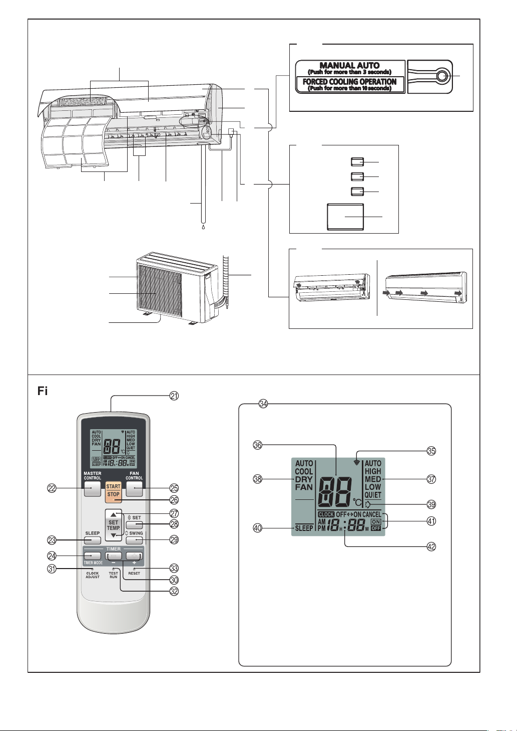
Fig. 1
Fig. 5
0
F
A
B
C
1
1
2
8
9
Fig.2
1
3
3
OPERATION
TIMER
SUPER QUIET
5
6
7
DE
4
Fig.3
8
Fig. 6
G
H
J
I
Fig.4
C
C
Fig. 7
To facilitate explanation, the accompanying illustration
has been drawn to show all possible indicators; in actral
operation, however, the display will only show those
indicators appropriate to the current operation.
Page 3
CONTENTS
SAFETY PRECAUTIONS ......................................En-1
FEATURES AND FUNCTIONS .............................En-2
NAME OF PARTS .................................................En-3
PREPARATION .....................................................En-4
OPERATION ..........................................................En-5
TIMER OPERATION .............................................En-7
SLEEP TIMER OPERATION .................................En-8
SAFETY PRECAUTIONS
DANGER!
● Do not attempt to install this air conditioner by yourself.
● This air conditioner contains no user-serviceable parts. Always consult authorized
service personnel for repairs.
● When moving, consult authorized service personnel for disconnection and installation
of the air conditioner.
● Do not become excessively chilled by staying for many hours in the direct cooling
airfl ow.
● Do not insert fi ngers or objects into the outlet port or intake grille.
● Do not start and stop air conditioner operation by disconnecting the power supply
cord and so on.
● Take care not to damage the power supply cord.
● In the event of a malfunction (burning smell, etc.), immediately stop operation,
disconnect the power supply plug, and consult authorized service personnel.
● If the power supply cord of this appliance is damaged, it should only be replaced by
the authorized service personal, since special purpose tools and specifi ed cord are
required.
MANUAL AUTO OPERATION ...............................En-8
ADJUSTING THE DIRECTION OF
AIR CIRCULATION ...............................................En-9
SWING OPERATION ..........................................En-10
CLEANING AND CARE .......................................En-10
TROUBLESHOOTING ........................................En-13
OPERATING TIPS ...............................................En-14
CAUTION!
● Provide occasional ventilation during use.
● Do not direct airfl ow at fi replaces or heating apparatus.
● Do not climb on, or place objects on, the air conditioner.
● Do not hang objects from the indoor unit.
● Do not set fl ower vases or water containers on top of air conditioners.
● Do not expose the air conditioner directly to water.
● Do not operate the air conditioner with wet hands.
● Do not pull power supply cord.
● Turn off power supply when not using the indoor unit for extended periods.
● Check the condition of the installation stand for damage.
● Do not place animals or plants in the direct path of the airfl ow.
● Do not drink the water drained from the air conditioner.
● Do not use in applications involving the storage of foods, plants or animals, precision
equipment, or art works.
● Connection valves become hot during Heating; handle with care.
● Do not apply any heavy pressure to radiator fi ns.
● Operate only with air fi lters installed.
● Do not block or cover the intake grille and outlet port.
● Ensure that any electronic equipment is at least one meter away from either the indoor
or outdoor units.
● Avoid installing the air conditioner near a fi replace or other heating apparatus.
● When installing the indoor and outdoor unit, take precautions to prevent access to
infants.
● Do not use infl ammable gases near the air conditioner.
En-1
Page 4
FEATURES AND FUNCTIONS
INVERTER
At the start of operation, a large power is used to bring the room
quickly to the desired temperature. Afterward, the air conditioner
automatically switches to a low power setting for economic and
comfortable operation.
AUTO CHANGEOVER
The operation mode (cooling, dry) is switched automatically
to maintain the set temperature, and the temperature is kept
constant at all times.
PROGRAM TIMER
The program timer allows you to integrate OFF timer and ON
timer operations in a single sequence. The sequence can involve
one transition from OFF timer to ON timer, or from ON timer to
OFF timer, within a twenty-four hour period.
SLEEP TIMER
When the SLEEP button is pressed during cooling mode, the
thermostat setting is gradually raised during the period of operation. When the set time is reached, the indoor unit automatically
turns off.
WIRELESS REMOTE CONTROL UNIT
The Wireless Remote Control Unit allows convenient control of
indoor unit operation.
SWING OPERATION
The Air Flow Direction Louvers swings automatically up and down
so that the air speeds to every nook and corner of your room.
REMOVABLE INTAKE GRILLE
The indoor unit’s Intake Grille can be removed for easy cleaning
and maintenance.
MILDEW-RESISTANT FILTER
The AIR FILTER has been treated to resist mildew growth, thus
allowing cleaner use and easier care.
SUPER QUIET OPERATION
When the FAN CONTROL button is used to select QUIET, the
indoor unit begins super-quiet operation; the indoor unit’s airfl ow
is reduced to produce quieter operation.
POLYPHENOL CATECHIN AIR CLEANING FILTER
The polyphenol catechin air cleaning fi lter uses static electricity
to clean fi ne particles and dust in the air such as tobacco smoke
and plant pollen that are too small to see.
The fi lter contains catechin, which is highly effective against
various bacteria by suppressing the growth of the bacteria adsorbed to the fi lter.
Note that when the air cleaning fi lter is installed, the amount of
air produced decreases, causing a slight decrease in the indoor
unit’s performance.
NEGATIVE AIR IONS DEODORIZING FILTER
It comprises pottery super micro particles which can produce
negative air ions having the effect of deodorizing and can absorb
and remit the peculiar smell at home.
En-2
Page 5
NAME OF PARTS
Fig. 1 Indoor Unit
1 Operating Control Panel (Fig. 2)
2 MANUAL AUTO button
When kept on pressing the MANUAL AUTO
●
button for more than 10 seconds, the forced
cooling operation will start.
● The forced cooling operation is used at the
time of installation.
Only for authorized service personnel’s use.
● When the forced cooling operation starts by
any chance, press the START/STOP button
to stop the operation.
3 Indicator (Fig. 3)
4 Remote Control Signal Receiver
5 OPERATION Indicator Lamp (green)
6 TIMER Indicator Lamp (orange)
If the TIMER indicator lamp fl ashes when the
●
timer is operating, it indicates that a fault has
occurred with the timer setting (See Page 14
Auto Restart).
7 SUPER QUIET Indicator Lamp (yellow)
8 Intake Grille (Fig. 4)
9 Front Panel
0 Air Filter
A Air Flow Direction Louver
B Right-Left Louver
(behind Air Flow Direction Louver)
C Drain Hose
D Power Supply Plug
E Power Supply Cord
F Air Cleaning Filter
Fig. 5 Outdoor Unit
G Intake Port
H Outlet Port
I Pipe Unit
J Drain port (bottom)
Fig. 6 Remote Control Unit
K Signal Transmitter
L MASTER CONTROL button
M SLEEP button
N TIMER MODE button
O FAN CONTROL button
P START/STOP button
Q SET TEMP. button (
/ )
R SET button
S SWING button
T TIMER SET ( / ) button
U CLOCK ADJUST button
V TEST RUN button
● This button is used when installing the conditioner, and should not be used under normal
conditions, as it will cause the air conditioner’s
thermostat function to operate incorrectly.
● If this button is pressed during normal operation, the unit will switch to test operation mode,
and the Indoor Unit’s OPERATION Indicator
Lamp and TIMER Indicator Lamp will begin
to fl ash simultaneously.
● To stop the test operation mode, press the
START/STOP button to stop the air condi-
tioner.
W RESET button
X Remote Control Unit Display (Fig. 7)
Y Transmit Indicator
Z Temperature SET Display
[ Fan Speed Display
\ Operating Mode Display
] SWING Display
` SLEEP Display
a T imer Mode Display
b Clock Display
● Refer to the folded out page on the cover.
En-3
Page 6
PREPARATION
Turn on the Power
Connect the Power Supply Plug (Fig. 1 D) to an electri-
1
cal outlet; in the case of a direct line connection, turn
on the circuit breaker.
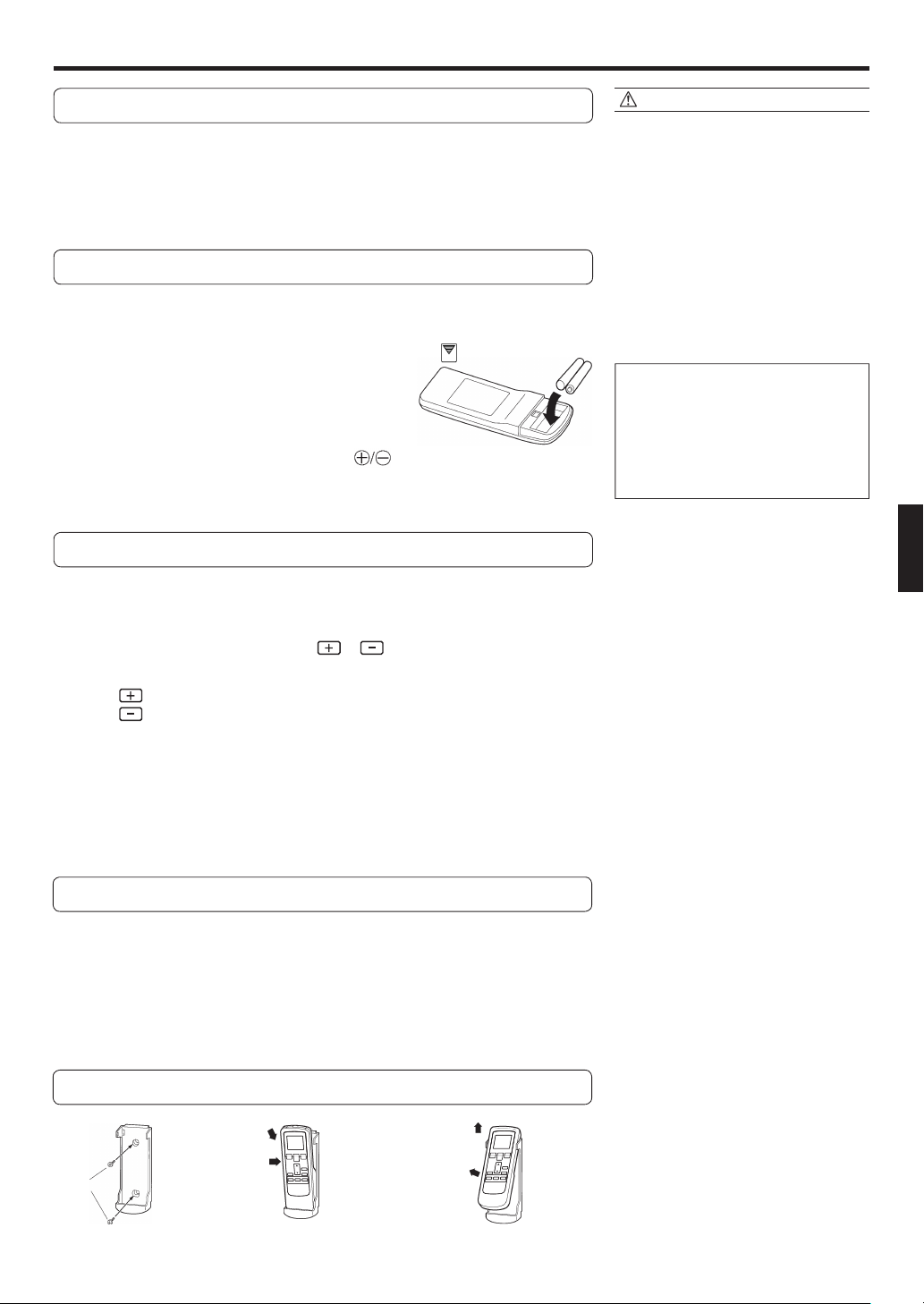
Load Batteries (Size AAA R03/LR03 × 2) *
Press and slide the battery compartment lid on the
1
reverse side to open it.
Slide in the direction of the arrow while pressing the mark.
* Batteries are not included with this product.
Insert batteries.
2
Be sure to align the battery polarities ( ) correctly.
Close the battery compartment lid.
3
Set the Current time
Press the CLOCK ADJUST button (Fig. 6 U).
1
Use the tip of a ball-point pen or other small object to press the button.
CAUTION!
● Take care to prevent infants from accidentally swallowing batteries.
● When not using the Remote Control Unit for
an extended period, remove the batteries to
avoid possible leakage and damage to the
unit.
● If leaking battery fl uid comes in contact
with your skin, eyes, or mouth, immediately
wash with copious amounts of water, and
consult your physician.
● Dead batteries should be removed immediately and disposed of properly, either
in a battery collection receptacle or to the
appropriate authority.
● Do not attem pt to recharge dry batteries.
Never mix new and used batteries, or batteries of different types.
Batteries should last about one year under
normal use. If the Remote Control Unit’s
operating range becomes appreciably
reduced, replace the batteries and press
the RESET button with the tip of a ballpoint
pen or other small object.
Use the TIMER SET ( / ) buttons (Fig. 6 T) to
2
adjust the clock to the current time.
button: Press to advance the time.
(Each time the buttons are pressed, the time will be advanced/reversed in one-
button: Press to reverse the time.
minute increments; hold the buttons depressed to change the time quickly in
ten-minute increments.)
Press the CLOCK ADJUST button (Fig. 6 U) again.
3
This completes the time setting and starts the clock.
To Use the Remote Control Unit
● The Remote Control Unit must be pointed at signal receiver (Fig. 3 4) to operate cor-
rectly.
● Operating Range: About 7 meters.
● When a signal is properly received by the air conditioner, a beeping sound will be
heard.
● If no beep is heard, press the Remote Control Unit button again.
Remote Control Unit Holder
Insert
Press in
Screws
Slide up
Pull out
1 Mount the Holder. 2 Set the Remote Control
Unit.
3 To remove the Remote Con-
trol Unit (when use at hand).
En-4
Page 7

OPERATION
To Select Mode Operation
Press the START/STOP button (Fig.6 P).
1
The indoor unit’s OPERATION Indicator Lamp (green) (Fig. 3 5) will light.
The air conditioner will start operating.
Press the MASTER CONTROL button (Fig.6 L) to select
2
the desired mode.
Each time the button is pressed, the mode will change in the following order.
AUTO COOL DRY FAN
About three seconds later, the entire display will reappear.
sss
s
To Set the Thermostat
Press the SET TEMP. button (Fig. 6 Q).
button: Press to raise the thermostat setting.
button: Press to lower the thermostat setting.
● Thermostat setting range:
AUTO ....................................18-30 °C
Cooling/Dry ...........................18-30 °C
The thermostat cannot be used to set room temperature during the FAN mode (the temperature will not appear on the Remote Control Unit’s Display).
About three seconds later, the entire display will reappear.
The thermostat setting should be considered a standard value, and may differ somewhat from the actual room temperature.
To Set the Fan Speed
Press the FAN CONTROL button (Fig. 6 O).
Each time the button is pressed, the fan speed changes in the following order:
AUTO HIGH MED LOW QUIET
About three seconds later, the entire display will reappear.
When set to AUTO:
Cooling : As the room temperature approaches that of the thermostat setting, the fan
speed becomes slower.
Fan : The fan runs at the low fan speed.
ssss
s
Example: When set to COOL.
Example: When set to 26 °C.
The fan will operate at a very low setting during Monitor operation.
SUPER QUIET Operation
When set to Quiet:
SUPER QUIET Indicatior Lamp (yellow) (Fig. 3 7) will right.
SUPER QUIET operation begins. The indoor unit’s airfl ow will be reduced for quieter
operation.
● SUPER QUIET operation cannot be used during Dry mode. (The same is true when
dry mode is selected during AUTO mode operation.)
● During Super Quiet operation, Cooling performance will be reduced somewhat. If the
room does not cool down when using SUPER QUIET Operation, please adjust the air
conditioner’s Fan Speed.
En-5
Example: When set to AUTO.
Page 8

To Stop Operation
Press the START/STOP button (Fig. 6 P).
The OPERATION Indicator Lamp (green) (Fig. 3 5) will go out.
About AUTO CHANGEOVER Operation
AUTO: ● When AUTO CHANGEOVER operation fi rst selected, the fan will operate
at very low speed for about one minute, during which time the unit detects
the room conditions and selects the proper operating mode.
If the differance between thermostat setting and actual room temperature
is more than +2 °C → Cooling or dry operation
If the difference between thermostat setting and actual room temperature
is within ±2 °C → Monitor operation
● When the air conditioner has adjusted your room’s temperature to near the
thermostat setting, it will begin monitor operation. In the monitor operation
mode, the fan will operate at low speed. If the room temperature subsequently
changes, the air conditioner will once again select the appropriate operation
(Cooling) to adjust the temperature to the value set in the thermostat.
(The monitor operation range is ±2 °C relative to the thermostat setting.)
● If the mode automatically selected by the unit is not what you wish, select
one of the mode operation (COOL, DRY, FAN).
About Mode Operation
Cooling: ● Use to cool your room.
Dry: ● Use for gently cooling while dehumidifying your room.
● You cannot heat the room during Dry mode.
● During Dry mode, the unit will operate at low speed; in order to adjust room
humidity, the indoor unit’s fan may stop from time to time. Also, the fan may
operate at very low speed when adjusting room humidity.
● The fan speed cannot be changed manually when Dry mode has been
selected.
Fan: ● Use to circulate the air throughout your room.
During Cooling/Dry mode:
Set the thermostat to a temperature setting
that is lower than the current room temperature. The Cooling and Dry modes will not
operate if the thermostat is set higher than
the actual room temperature (in Cooling
mode, the fan alone will operate).
During Fan mode:
You can not use the unit to heat and cool
your room.
En-6
Page 9

TIMER OPERATION
Before using the timer function, be sure that the Remote Control Unit is set to the correct current time (☞ P. 4).
To Use the ON timer or OFF timer
Press the START/STOP button (Fig. 6 P)
1
(if the unit is already operating, proceed to step 2).
The indoor unit’s OPERATION Indicator Lamp (green) (Fig. 3 5) will light.
Press the TIMER MODE button (Fig. 6 N) to select the
2
OFF timer or ON timer operation.
Each time the button is pressed the timer function changes in the following
order:
CANCEL OFF ON
PROGRAM(OFF → ON, OFF ← ON)
The indoor unit’s TIMER Indicator Lamp (orange) (Fig. 3 6) will light.
ss
s
t
Use the TIMER SET buttons (Fig. 6 T) to adjust the
3
desired OFF time or ON time.
Set the time while the time display is fl ashing (the fl ashing will continue for
about fi ve seconds).
button: Press to advance the time.
button: Press to reverse the time.
About fi ve seconds later, the entire display will reappear.
To Use the Program timer
To Cancel the Timer
Use the TIMER button to select “CANCEL”.
The air conditioner will return to normal operation.
To Change the Timer Settings
Perform steps 2 and 3.
To Stop Air Conditioner Operation while
the Timer is Operating
Press the START/STOP button.
To Change Operating Conditions
If you wish to change operating conditions
(Mode, Fan Speed, Thermostat Setting,
SUPER QUIET mode), after making the timer
setting wait until the entire display reappears,
then press the appropriate buttons to change
the operating condition desired.
Press the START/STOP button (Fig. 6 P).
1
(if the unit is already operating, proceed to step 2).
The indoor unit’s OPERATION Indicator Lamp (green) (Fig. 3 5) will light.
Set the desired times for OFF timer and ON timer.
2
See the section “To Use the ON timer or OFF timer” to set the desired mode
and times.
About three seconds later, the entire display will reappear.
The indoor unit’s TIMER Indicator Lamp (orange) (Fig. 3 6) will light.
Press the TIMER MODE button (Fig. 6 N) to select the
3
PROGRAM timer operation (OFF ON or OFF ON
will display).
The display will alternately show “OFF timer” and “ON timer”, then change to
show the time setting for the operation to occur fi rst.
● The program timer will begin operation. (If the ON timer has been selected
to operate fi rst, the unit will stop operating at this point.)
About fi ve seconds later, the entire display will reappear.
About the Program timer
● The program timer allows you to integrate OFF timer and ON timer operations in a
single sequence. The sequence can involve one transition from OFF timer to ON timer,
or from ON timer to OFF timer, within a twenty-four hour period.
● The fi rst timer function to operate will be the one set nearest to the current time. The
order of operation is indicated by the arrow in the Remote Control Unit’s Display
(OFF → ON, or OFF ← ON).
● One example of Program timer use might be to have the air conditioner automatically
stop (OFF timer) after you go to sleep, then start (ON timer) automatically in the morning before you arise.
En-7
To Cancel the Timer
Use the TIMER MODE button to select “CANCEL”.
The air conditioner will return to normal operation.
To Change the Timer Settings
Follow the instructions given in the section “To
1.
Use the ON Timer or OFF Timer” to select the
timer setting you wish to change.
2. Press the TIMER MODE button to select
either OFF ON or OFF ON.
To Stop Air Conditioner Operation while
the Timer is Operating
Press the START/STOP button.
To Change Operating Conditions
If you wish to change operating conditions
(Mode, Fan Speed, Thermostat Setting, SUPER
QUIET mode), after making the timer setting
wait until the entire display reappears, then
press the appropriate buttons to change the
operating condition desired.
Page 10

SLEEP TIMER OPERATION
Unlike other timer functions, the SLEEP timer is used to set the length of time until air conditioner operate is stopped.
To Use the SLEEP Timer
While the air conditioner is operating or stopped, press the
SLEEP button (Fig. 6 M).
The indoor unit’s OPERATION Indicator Lamp (green) (Fig. 3 5) lights and the TIMER
Indicator Lamp (orange) (Fig. 3 6) light.
To Change the Timer Settings
Press the SLEEP button (Fig. 6 M) once again and set the time
using the TIMER SET ( / ) buttons (Fig. 6 T).
Set the time while the Timer Mode Display is fl ashing (the fl ashing will continue about
fi ve seconds).
button: Press to advance the time.
button: Press to reverse the time.
About fi ve seconds later, the entire display will reappear.
About the SLEEP Timer
To prevent excessive cooling during sleep, the SLEEP timer function automatically modifi es the thermostat setting in accordance with
the set time setting. When the set time has elapsed, the air conditioner completely stops.
To Cancel the Timer:
Use the TIMER MODE button to select “CANCEL”.
The air conditioner will return to normal operation.
To Stop the Air Conditioner During
Timer Operation:
Press the START/STOP button.
During Cooling/Dry operation:
When the SLEEP timer is set, the thermostat setting is automatically raised 1 °C every sixty minutes. When the thermostat has been
raised a total of 2 °C, the thermostat setting at that time is maintained until the set time has elapsed, at which time the air conditioner
automatically turns off.
SLEEP timer setting
Set time
1 hour
1 °C
2 °C
MANUAL AUTO OPERATION
Use the MANUAL AUTO operation in the event the Remote Control Unit is lost or otherwise unavailable.
How To Use the Main Unit Controls
Press the MANUAL AUTO button (Fig. 2 2) for three seconds
on the main unit control panel.
To stop operation, press the MANUAL AUTO button (Fig. 2 2) for three seconds.
● When the air conditioner is operated by
the controls on the Main Unit, it will operate under the same mode as the AUTO
mode selected on the Remote Control
Unit (see page 6).
● The fan speed selected will be “AUTO”
and the thermostat setting will be standard (24
°C).
En-8
Page 11

ADJUSTING THE DIRECTION OF AIR CIRCULATION
Vertical (up-down) direction of airfl ow is adjusted by pressing the Remote Control Unit’s SET button. Horizontal (right-left) airfl ow direc-
tion is adjusted manually, by moving the Air Flow Direction Louvers.
Whenever making horizontal airfl ow adjustments, start air conditioner operation and be sure that the vertical air direction louvers are
stopped.
Vertical Air Direction Adjustment
Press the SET button (Fig. 6 R).
Each time the button is pressed, the air direction range will change as follows:
1
Types of Air fl ow Direction Setting:
1,2,3 : During Cooling/Dry modes
1,2,3,4,5,6 : During Fan mode
The Remote Control Unit’s display does
not change.
● Use the air direction adjustments within the ranges shown above.
● The vertical airfl ow direction is set automatically as shown, in accordance with the type
of operation selected.
During Cooling/Dry/Fan mode
● During AUTO mode operation, for the fi rst one minute after beginning operation, airfl ow
will be horizontal 1; the air direction cannot be adjusted during this period.
2 3 4 5 6
1
2
3
4
5
6
: Horizontal fl ow 1
DANGER!
● Never place fi ngers or foreign objects inside
the outlet ports, since the internal fan operates
at high speed, and personal injury could be
caused.
● Always use the Remote Control Unit’s
SET button to adjust the vertical airfl ow
louvers. Attempting to move them manually could result in improper operation; in
this case, stop operation and restart. The
louvers should begin to operate properly
again.
● During use of the Cooling and Dry modes,
do not set the Airfl ow Direction Louvers in
the range (4 - 6) for many hours, since
water vapor may condense near the outlet louvers and drops of water may drip
from the indoor unit. During the Cooling
and Dry modes, if the Airfl ow Direction
Louvers are left in the range (4 - 6) for
more than 30 minutes, they will automatically return to position 3.
● When used in a room with infants, children, elderly or sick persons, the airfl ow
direction and room temperature should
be considered carefully when making
settings.
Right-Left Adjustment
Adjust the Right-Left louvers.
● Move the Right-Left louvers to adjust air fl ow in the direction you prefer.
Right-Left Louvers
knob
knob(two places)
DANGER!
● When adjusting the Right-Left Louvers, it is
necessary to stop the Air-Conditioner fi rst
and make sure that it stops completely before
adjusting the direction.
En-9
Page 12

SWING OPERATION
Begin air conditioner operation before performing this procedure.
To select SWING Operation
Press the SWING button (Fig. 6 S).
The SWING Display (Fig. 7 ]) will light.
In this mode, the Air Flow Direction Louvers will swing automatically to direct the air fl ow
both up and down.
To stop SWING Operation
Press the SWING button (Fig. 6 S) once again.
The SWING Display (Fig. 7 ]) will go out.
Airfl ow direction will return to the setting before swing was begun.
About Swing Operation
● The SWING operation may stop temporarily when the air conditioner’s fan is not operating,
or when operating at very low speeds.
● The range of swing is relative to the currently set airfl ow direction.
During Cooling/Dry mode : Swings between 1 and 3.
During Fan mode : Swings between 1 and 3 or 3 and 6.
CLEANING AND CARE
CAUTION!
● To avoid excessive wear of the part and components or malfunctioning of the air conditioning, the user/consumer shall perform
preventive maintenance through an accredited technical assistance, periodically. To know the preventive maintenance periodicity,
the consumer shall check with the accredited installer or an accredited technical assistance.
● When used for extended periods, the unit may accumulate dirt inside, reducing its performance. We recommend that the unit be
inspected regularly, in addition to your own cleaning and care. For more information, consult authorized service personnel.
● It is recommended for the user/consumer to demand a copy of the Work Order every time there is a visit of a technical assistance
for verifi cation, maintenance, test or repair of the product.
● When cleaning the unit’s body, do not use water hotter than 40 °C, harsh abrasive cleansers, or volatile agents like benzene or
thinner.
● Do not expose the unit body to liquid insecticides or hairsprays.
● When shutting down the unit for one month or more, fi rst allow the fan mode to operate continuously for about one-half day to
allow internal parts to dry thoroughly.
● Before cleaning the indoor unit, be sure to turn it off and disconnect the Power Supply Cord.
● Be sure the Intake Grille (Fig. 1 8) is installed securely.
● When removing or replacing the air fi lters, be sure not to touch the heat exchanger, as personal injury
may result.
En-10
Page 13

CLEANING AND CARE
Cleaning the Intake Grille
1. Remove the Intake Grille.
1 Place your fi ngers at both lower ends of the grille panel,
and lift forward; if the grille seems to catch partway through
its movement, continue lifting upward to remove.
2 Pull past the intermediate catch and open the Intake Grille
wide so that it become horizontal.
Intake Grille
Mounting
shaft
Knob
2. Clean with water.
Remove dust with a vacuum cleaner; wipe the indoor unit
with warm water, then dry with a clean, soft cloth.
3. Replace the Intake Grille.
1 Pull the knobs all the way.
2 Hold the grille horizontal and set the left and right mounting
shafts into the bearings at the top of the panel.
3 Press the place where the arrow on the diagram indicates
and close the Intake Grille.
Cleaning the Air Filter
1. Open the Intake Grille, and remove the air
fi lter.
Lift up the air fi lter’s handle, disconnect the two lower tabs,
and pull out.
Air fi lter handle
Air fi lter (Right & Left)
Hooks(two places)
2. Remove dust with a vacuum cleaner or by
washing.
After washing, allow to dry thoroughly in a shaded place.
3. Replace the Air Filter and close the Intake
Grille.
1 Align the sides of the air fi lter with the panel, and push in
fully, making sure the two lower tabs are returned properly
to their holes in the panel.
Hooks(two places)
2 Close the Intake Grille.
(For purposes of example, the illustration shows the indoor unit
without Intake Grille installed.)
● Dust can be cleaned from the air fi lter either with a vacuum
cleaner, or by washing the fi lter in a solution of neutral deter-
gent and warm water. If you wash the fi lter, be sure to allow
2
Mounting
1
3
shaft
Bearing
Knob
2
1
3
it to dry thoroughly in a shady place before reinstalling.
● If dust is allowed to accumulate on the air fi lter, airfl ow will
be reduced, lowering operating effi ciency and increasing
noise.
● During periods of normal use, the Air Filters should be cleaned
every two weeks.
● Don't operate the air conditioner with being opened the intake
grille.
En-11
Page 14

CLEANING AND CARE
Air Cleaning Filter Installation
1. Open the Intake Grille and remove the Air
fi lters.
2. Attach the air cleaning fi lter to the frame
of the front panel.
● Attach the fi lter on the inside of the tabs (6 places) so as
not to stick out.
Air cleaning fi lter frame
Tabs (6 places)
Air fi lter
(In the above fi gure, the intake grille is omitted for the
explanation)
Tabs
(6 places)
3. Install the two Air fi lters and close the
Intake Grille.
● Don't operate the air conditioner with being opened the
intake grille.
● When air cleaning fi lters are used, the effect will increased by
setting the fan speed to “High”.
2. Remove the air cleaning fi lters attached to
the frames of the front panel.
Air cleaning fi lter frame
Air fi lter
3. Replace them by two new Air cleaning
fi lters.
1 Remove the old air cleaning fi lters in reverse order of their
installation.
2 Install in the same way as for installation of the air cleaning
fi lter set.
4. Install the two Air fi lters and close the
Intake Grille.
● Don't operate the air conditioner with being opened the
intake grille.
About the Air Cleaning Filters
POLYPHENOL CATECHIN AIR CLEANING FILTER
● The Air Cleaning Filters are disposable fi lters. (They can not
be washed and reused.)
● For storage of the Air Cleaning Filters, use the fi lters as soon
as possible after opening the package.
(The air cleaning effect decreases when the fi lters are left in
the opened package)
● Generally, the fi lters should be exchanged about every three
months.
Please buy designed air cleaning fi lters (UTR-FA16) (Sold
separately) to exchange the used dirty air cleaning fi lter.
[Negative air ions deodorizing fi lter (one sheet) — light blue]
● The fi lter should be exchanged about every three years so
as to maintain the deodorizing effect.
(one sheet)
Replacing dirty Air cleaning fi lters
Replace fi lters with the following components (purchased sepa-
rately).
●
POLYPHENOL CATECHIN AIR CLEANING FILTER
● Negative air ions deodorizing fi lter: UTR-FA16-2
: UTR-FA16
1. Open the Intake Grille and remove the Air fi l-
ters.
Please buy designed deodorizing fi lter (UTR-FA16-2) (Sold
separately) when exchanging the fi lter.
Maintenance of Deodorizing Filters
In order to maintain the deodorizing effect, please clean the fi lter
in the follow way once three months.
1 Remove the deodorizing fi lter.
2 Clean with water and dry in the air.
1) Flush the fi lter with high-pressure hot water until the
surface of the fi lter is covered with water. Please fl ush
with diluent neutral detergent.
Never wash by reaming or rubbing, otherwise it will
damage the deodorizing effect.
2) Rinse with water fl ow.
3) Dry in shade.
3 Reinstall the deodorizing fi lter.
En-12
Page 15

TROUBLESHOOTING
WARNING!
Before requesting service, perform the following checks:
NORMAL
FUNCTION
Doesn’t operate immediately:
Noise is heard:
Smells:
Mist or steam are
emitted:
In the event of a malfunction (burning smell, etc.), immediately stop operation, turn off the electrical
breaker or disconnect the power supply plug, and consult authorized service personnel.
Merely turning off the unit’s power switch will not completely disconnect the unit from the power source.
Always be sure to turn off the electrical breaker or disconnect the power supply plug to ensure that
power is completely off.
Symptom Problem
● If the unit is stopped and then immediately started again, the compressor will not operate for about 3 minutes, in order to prevent fuse
blowouts.
Whenever the Power Supply Plug is disconnected and then recon-
●
nected to a power outlet, the protection circuit will operate for about
3 minutes, preventing unit operation during that period.
● During operation and immediately after stopping the unit, the sound
of water fl owing in the air conditioner’s piping may be heard. Also,
noise may be particularly noticeable for about 2 to 3 minutes after
starting operation (sound of coolant fl owing).
● During operation, a slight squeaking sound may be heard. This is the
result of minute expansion and contraction of the front cover due to
temperature changes.
● Some smell may be emitted from the indoor unit. This smell is the
result of room smells (furniture, tobacco, etc.) which have been taken
into the air conditioner.
● During Cooling or Dry operation, a thin mist may be seen emitted
from the indoor unit. This results from the sudden Cooling of room air
by the air emitted from the air conditioner, resulting in condensation
and misting.
See Page
—
—
—
—
Airfl ow is weak or stops:
CHECK ONCE
MORE
If the problem persists after performing these checks, or if you notice burning smells, or the OPERATION Indicator Lamp (Fig. 3
5) and the TIMER Indicator Lamp (Fig. 3 6) fl ashes, immediately stop operation, disconnect the Power Supply Plug (Fig. 1 D), and
consult authorized service personnel.
Doesn’t operate at all:
Poor Cooling performance:
The unit operates
differently from the Remote
Control Unit’s setting:
● The fan may operate at very low speed during Dry operation or when
the unit is monitoring the room’s temperature.
During SUPER QUIET operation, the fan will operate at very low speed.
●
In the monitor AUTO operation, the fan will operate at very low speed.
●
● Is the Power Supply Plug disconnected its outlet?
● Has there been a power failure?
● Has a fuse blown out, or a circuit breaker been tripped?
● Is the timer operating?
● Is the Air Filter dirty?
● Air the air conditioner’s intake grille or outlet port blocked?
●
Did you adjust the room temperature settings (thermostat) correctly?
● Is there a window or door open?
● In the case of Cooling operation, is a window allowing bright sunlight
to enter? (Close the curtains.)
●
In the case of Cooling operation, are there heating apparatus and computers inside the room, or are there too many people in the room?
● Is the unit set for SUPER QUIET operation?
● Are the Remote Control Unit’s batteries dead?
● Are the Remote Control Unit’s batteries loaded properly?
5
5
5
—
7-8
—
5
4
En-13
Page 16

OPERATING TIPS
AUTO Restart
In Event of Power Interruption
● The power supply to the air conditioner is stopped by a power
interruption. The air conditioner will then restart automatically
in its previous mode when the power is restored.
Temperature and Humidity Range
●
If a power interruption occurs during TIMER operation, the timer
will be reset and the indoor unit will begin (or stop) operation at
the new time setting. In the event that this kind of timer fault occurs, the TIMER Indicator Lamp will fl ash (see Page. 3).
● Use of other electrical appliances (electric shaver, etc.) or
nearby use of a wireless radio transmitter may cause the air
conditioner to malfunction. In this event, temporarily disconnect the Power Supply Plug, reconnect it, and then use the
Remote Control Unit to resume operation.
Cooling Mode
Outdoor temperature
Indoor temperature
● If the air conditioner is used under higher temperature conditions than those listed, the built-in protection circuit may operate to prevent internal circuit damage. Also, during Cooling and Dry modes, if the air conditioner is used under conditions of lower temperature
than those listed above, the heat-exchanger may freeze, leading to water leakage and other damage.
● Do not use this air conditioner for any purposes other than the Cooling, Dehumidifying, and air-circulation of rooms in ordinary dwellings.
● If the air conditioner is used for many hours under high-humidity conditions about 80% or more, condensation may form on the
surface of the indoor unit, and drip onto the fl oor or other objects underneath.
About 18 to 46 °C
About 18 to 32 °C
Dry Mode
About 18 to 46 °C
About 18 to 32 °C
En-14
Page 17

Page 18

 Loading...