

Page 1
R410A
D2D_AR028E/03
2008.04.08
1. DUCT
TYPE :
AR A12LALU
AR F12LALU
AR A14LALU
AR F14LALU
INDOOR UNIT
Page 2

DUCT TYPE
AR A12-14L
DUCT TYPE
AR A12-14L
1. FEATURE
FEATURES
FUNCTION SETTING
Energy saving (AO A12LACL, AO A12LALL, AO A14LACL, AO A14LALL connection model)
MODEL :
High energy saving was realized by making the indoor unit and outdoor
unit fan motor and compressor all DC and optimal design of the refrigerant cycle. Rank A was achieved in European energy rank.
Quiet operation
Quiet operation possible by quiet mode.
* See our measurement conditions page (01-26).
Static pressure mode setting
Air flow, noise, etc. can be used under the optimum conditions by selecting
the static pressure mode matched to the installation conditions.
Room temperature adjustment correction
Suitable room temperature control is performed by changing the room temperature
correction value by simple remote control operation to match the conditions under
which the air conditioner is installed.
Auto restart
The units restart automatically when the current was returned even when
there was a power interruption during operation.
Universal design indoor unit
Thin and compact indoor unit
Since vertical and horizontal installation is possible, and the intake direction can also be selected
from two directions, flexible installation is possible.
Ceiling concealed Floor concealed
12 type 14 type
*26 dB(A) *27 dB(A)
- (01 - 01) -
INDOOR UNIT
OUTDOOR UNIT
AR A12LALU AO A12LACL AO B12LACL
AR F12LALU AO A12LALL AO B12LALL
AR A14LALU AO A14LACL AO B14LACL
AR F14LALU AO A14LALL AO B14LALL
Page 3

Page 4
Page 5

DUCT TYPE
AR A12-14L
DUCT TYPE
AR A12-14L
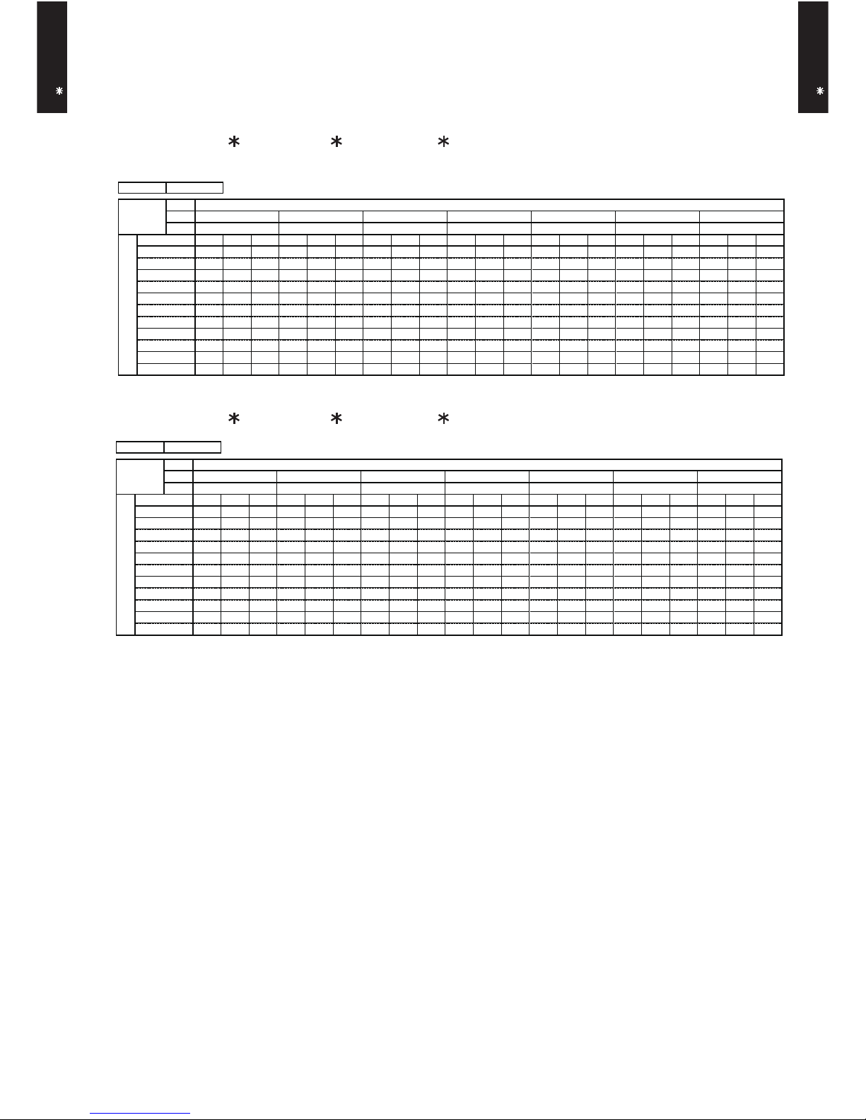
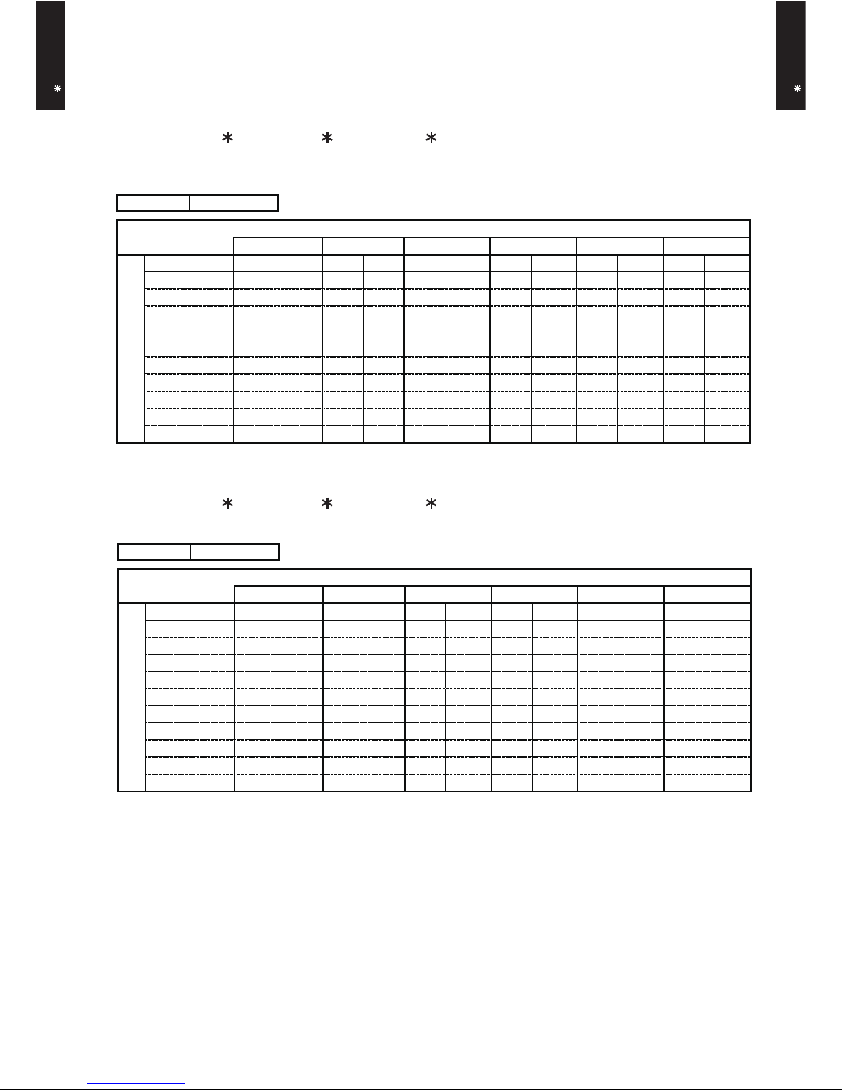
3. SPECIFICATIONS
Note :
Specifications are based on the following conditions.
Cooling : Indoor temperature of 27 °CDB / 19 °CWB.and outdoor temperature of 35 °CDB/24°CWB.
Heating : Indoor temperature of 20 °CDB / 15 °CWB.and outdoor temperature of 7 °CDB/6 °CWB.
Standard static pressure : 0 Pa
Pipe length : 7.5 m, Height difference : 0 m.(Outdoor unit - Indoor unit)
Sound pressure level : Install a 2m duct to the outlet port and a 1m duct to the suction port and measure.
*The maximum current are the maximum input value and the maximum values when operated within the operation (temperature)range
- (01 - 04) -
A R A 1 2 L A L U
A R F12L A L U
A R A 1 4 L A L U
A R F14L A L U
A O A 1 2 L A C L
A O A 1 2 L A L L
A O A 1 4 L A C L
A O A 1 4 L A L L
C o o lin g A A
H e a tin g A A
kW 3.5 0 4.3 0
B T U /h 1195 0 1465 0
kW 0.9 0 - 4 .4 0 0.9 0 - 5 .4 0
B T U /h 3100 - 1 50 0 0 3 10 0 - 1 84 0 0
kW 4.1 0 5.0 0
B T U /h 1400 0 1705 0
kW 0.9 0 - 5 .7 0 0.9 0 - 6 .5 0
B T U /h 3100 - 1 94 0 0 3 10 0 - 2 21 0 0
1.0 5 1.3 3
1.7 3 2.0 7
1.1 1 1.3 4
2.3 0 2.8 8
4.6 5.8
7.5 9.0
4.9 5.9
10.0 12.5
E E R 3.3 3 3.2 1
C O P 3.6 9 3.7 1
l/h (p in ts/h )
1.3 ( 2 .3 ) 1.5 ( 2 .6 )
H ig h 720 870
M e d 6 3 0 7 7 0
Low 56 0 6 7 0
Q u ie t 480 580
H ig h 720 870
M e d 6 3 0 7 7 0
Low 56 0 6 7 0
Q u ie t 480 580
Typ e × Q'ty
M o to r o u tp ut W
R e com m en d e d s tatic p res s u re P a
H ig h 32 33
M e d 30 3 1
Low 2 8 2 9
Q u ie t 26 2 7
H ig h 32 33
M e d 30 3 1
Low 2 8 2 9
Q u ie t 26 2 7
D im en si on s ( H × W × D )
294 × 7 0 0 × 26 .6 294 × 7 0 0 × 26 .6
Fin p itch 1.3 0 1.3 0
R o w s x S ta ge s 2 × 14 2 × 1 4
P ip e ty p e
Fin t y p e
M a te rial
C o lo u r - -
N e t
G ro ss
N e t 23 ( 5 1 ) 23 ( 5 1 )
G ro ss 27 ( 6 0 ) 27 ( 6 0 )
Liq u id
G a s
9.5 2 ( 3 / 8 in .) 12.7 0 ( 1 / 2 in. )
M e th od
°C
% R H
H e a tin g °C
m m
d B (A)
R e m o t e c o n tro ll e r ty pe
D ra in p ipe
M a te rial
S iz e
O p e ra tio n r a n g e
C o o lin g
kg (lb .)
C o n n e c tion
pip e
S iz e m m
W eig ht
m3/h
Fan
D im en s io n s
( H × W × D )
m m
A irflo w
ra te
E n clo s u re
H e a t e x chang e r ty p e
S o u n d p res s u re le ve l
H e a tin g
C o o lin g
H e a tin g
H e a tin g
C o o lin g
M o is tu re re mo v a l
C o o lin g
H e a tin g
R a te d
*M ax.
R a te d
*M ax.
kW /k W
In p u t p o w er
C o o lin g
kW
H e a tin g
R a te d
*M ax.
C u rr e n t
C o o lin g
A
A vaila ble vo lta g e r a n g e
C a p a c ity
C o o lin g
H e a tin g
E u ro pe a n e ne rg y la be l
Typ e
m m
R a te d
M in .-M ax.
R a te d
M in .-M ax.
R a te d
*M ax.
P o w e r s o u rc e
D U C T E D M OD EL
IN V ER T E R H EA TP U M P
230V 50H z
198-2 6 4V 5 0 H z
S irocc o × 2
60
0 to 9 0
C o p p e r
A lu m inium
S te el
217 × 9 53 × 5 9 5
324 × 1 0 7 5 × 68 6
M o d e l n a m e
W ire d
P S
O u te r d ia me ter : 26 .0 / In n e r dia m ete r : 2 1 .5
6.3 5 ( 1 / 4 in.)
Fla re
18 to 3 2
80 o r le ss
30 o r le ss
Page 6

- (01 - 05) -
Note :
Specifications are based on the following conditions.
Cooling : Indoor temperature of 27 °CDB / 19 °CWB.and outdoor temperature of 35 °CDB/24°CWB.
Heating : Indoor temperature of 20 °CDB / 15 °CWB.and outdoor temperature of 7 °CDB/6 °CWB.
Standard static pressure : 0 Pa
Pipe length : 7.5 m, Height difference : 0 m.(Outdoor unit - Indoor unit)
Sound pressure level : Install a 2m duct to the outlet port and a 1m duct to the suction port and measure.
*The maximum current are the maximum input value and the maximum values when operated within the operation (temperature)range
DUCT TYPE
AR A12-14L
DUCT TYPE
AR A12-14L
A R A 1 2 L A L U
A R F12L A L U
A R A 1 4 L A L U
A R F14L A L U
A O B 1 2 L A C L
A O B 1 2 L A L L
A O B 1 4 L A C L
A O B 1 4 L A L L
C o o lin g B B
H e a tin g B B
kW 3.5 0 4.3 0
B T U /h 119 5 0 146 5 0
kW 0.9 0 - 4 .3 0 0.9 0 - 5 .2 0
B T U /h 310 0 - 1 46 5 0 3 10 0 - 1 77 5 0
kW 4.1 0 5.0 0
B T U /h 140 0 0 170 5 0
kW 0.9 0 - 5 .5 0 0.9 0 - 6 .3 0
B T U /h 310 0 - 1 87 5 0 3 10 0 - 2 15 0 0
1.1 1 1.4 1
1.7 3 2.0 7
1.1 7 1.4 2
2.3 0 2.8 8
4.9 6.2
7.5 9.0
5.1 6.2
10.0 12.5
E E R 3.1 5 3.0 5
C O P 3.5 0 3.5 2
l/h (p in ts/h )
1.3 ( 2 .3 ) 1.5 ( 2 .6 )
H ig h 720 870
M e d 6 3 0 7 7 0
Low 56 0 6 7 0
Q u ie t 480 580
H ig h 720 870
M e d 6 3 0 7 7 0
Low 56 0 6 7 0
Q u ie t 480 580
Typ e × Q'ty
M o to r o u tp ut W
R e com m en d e d s tatic p res s u re P a
H ig h 32 33
M e d 30 3 1
Low 2 8 2 9
Q u ie t 26 2 7
H ig h 32 33
M e d 30 3 1
Low 2 8 2 9
Q u ie t 26 2 7
D im en si on s ( H × W × D )
294 × 7 0 0 × 26 .6 294 × 7 0 0 × 26 .6
Fin p itch 1.3 0 1.3 0
R o w s x S ta ge s 2 × 1 4 2 × 1 4
P ip e ty p e
Fin t y p e
M a te rial
C o lo u r
- -
N e t
G ro ss
N e t 23 ( 5 1 ) 23 ( 5 1 )
G ro ss 27 ( 6 0 ) 27 ( 6 0 )
Liq u id
G a s 9.5 2 ( 3 / 8 in .) 12.7 0 ( 1 / 2 in. )
M e th od
°C
% R H
H e a tin g °C
m m
R e m o t e c o n tro ll e r ty pe W ire d
D ra in p ipe
M a te rial P S
S iz e O u te r d ia me ter : 26 .0 / In n e r dia m ete r : 2 1 .5
6.3 5 ( 1 / 4 in.)
Fla re
O p e ra tio n r a n g e
C o o lin g
18 to 3 2
80 o r le ss
30 o r le ss
W eig ht kg (l b .)
C o n n e c tion
pip e
S iz e m m
E n clo s u re
S te el
D im en s io n s
( H × W × D )
m m
217 × 9 53 × 5 9 5
324 × 1 0 7 5 × 68 6
H e a t e x chang e r ty p e
m m
C o p p e r
A lu m inium
S irocc o × 2
60
0 to 9 0
S o u n d p res s u re le ve l
C o o lin g
d B (A)
H e a tin g
Fan
A irflo w
ra te
C o o lin g
m3/h
H e a tin g
C o o lin g
kW /k W
H e a tin g
M o is tu re re mo v a l
C u rr e n t
C o o lin g
R a te d
A
*M ax.
H e a tin g
R a te d
*M ax.
In p u t p o w er
C o o lin g
R a te d
kW
*M ax.
H e a tin g
R a te d
*M ax.
E u ro pe a n e ne rg y la be l
C a p a c ity
C o o lin g
R a te d
M in .-M ax.
H e a tin g
R a te d
M in .-M ax.
P o w e r s o u rc e 230V 50H z
A vaila ble vo lta g e r a n g e 198-2 6 4V 5 0 H z
Typ e
D U C T E D M OD EL
IN V ER T E R H EA TP U M P
M o d e l n a m e
Page 7

DUCT TYPE
AR A12-14L
DUCT TYPE
AR A12-14L
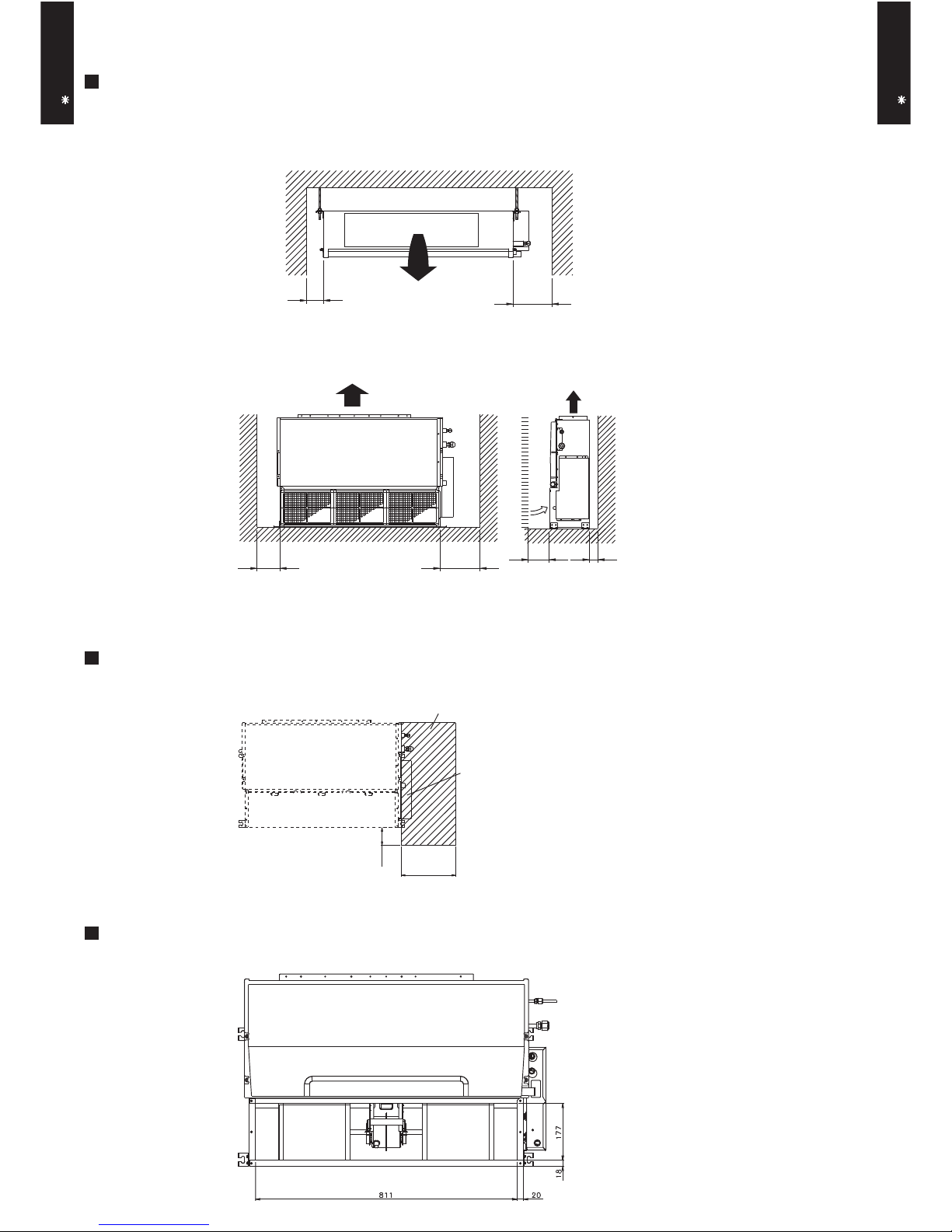
4. DIMENSIONS
MODEL : AR A12L, AR F12L, AR A14L, AR F14L
(Unit : mm)
886
953
850
920
600
150
150
595
57520
85 75
364
390
194
217
BRACKETS
AIR FLOW OUTLET
CONTROL BOX
COUPLING PIPE ASSY
DRAIN PORT
1
Refrigerant piping flare connection (Gas)
Refrigerant piping flare connection (Liquid)
Drain piping connection
2
3
12
3
1
2
Top view
Front view
Side view
- (01 - 06) -
Page 8
DUCT TYPE
AR A12-14L
DUCT TYPE
AR A12-14L
MOUNTING POSITION
MAINTENANCE HOLE
(Unit : mm)
Left
side
Right
side
100 or more
300 or more
Strong and durable ceiling
Indoor unit
Left
side
Right side
(PIPE side)
Strong and durable floor
100 or more 300 or more
30
or more30or more
Maintenance hole
Unit
100
or more
Control box
300
or more
BOTTOM AIR INTAKE HOLE
- (01 - 07) -
Page 9

DUCT TYPE
AR A12-14L
DUCT TYPE
AR A12-14L
5. WIRING DIAGRAMS
- (01 - 08) -
MODEL : AR A12L, AR F12L, AR A14L, AR F14L
Page 10
AR A12L, AR F12L / AO A12L
- (01 - 09) -
°CDB
°CWB
TC SHC PI TC SHC PI TC SHC PI TC SHC PI TC SHC PI TC SHC PI TC SHC PI
3.52 3.13 0.31 3.92 3.15 0.31 4.05 3.42 0.32 4.32 3.43 0.32 4.46 3.70 0.32 4.72 3.69 0.32 4.99 3.93 0.33
3.33 3.00 0.51 3.71 3.02 0.52 3.84 3.28 0.52 4.09 3.29 0.53 4.22 3.55 0.53 4.47 3.54 0.54 4.73 3.77 0.54
3.33 3.00 0.49 3.71 3.02 0.50 3.84 3.28 0.50 4.09 3.29 0.51 4.22 3.55 0.51 4.47 3.54 0.52 4.73 3.77 0.52
3.33 2.99 0.45 3.71 3.01 0.46 3.84 3.27 0.46 4.09 3.29 0.46 4.21 3.55 0.47 4.47 3.53 0.47 4.72 3.76 0.48
3.22 2.92 0.55 3.59 2.94 0.56 3.71 3.19 0.56 3.95 3.20 0.57 4.08 3.46 0.57 4.32 3.44 0.58 4.57 3.67 0.58
4.20 3.60 1.29 4.68 3.63 1.31 4.84 3.94 1.32 5.16 3.95 1.33 5.32 4.27 1.34 5.64 4.25 1.35 5.95 4.53 1.36
4.03 3.49 1.44 4.49 3.51 1.46 4.64 3.81 1.47 4.95 3.83 1.48 5.10 4.13 1.49 5.41 4.11 1.51 5.71 4.38 1.52
3.80 3.32 1.53 4.23 3.34 1.56 4.37 3.63 1.56 4.66 3.64 1.58 4.81 3.93 1.59 5.09 3.92 1.60 5.38 4.17 1.62
3.48 3.10 1.54 3.88 3.12 1.57 4.01 3.39 1.57 4.27 3.40 1.59 4.40 3.67 1.60 4.67 3.65 1.61 4.93 3.89 1.63
2.93 2.72 1.31 3.26 2.74 1.33 3.37 2.98 1.33 3.59 2.99 1.35 3.70 3.22 1.35 3.93 3.21 1.37 4.15 3.42 1.38
2.16 2.20 1.01 2.40 2.21 1.03 2.48 2.40 1.03 2.65 2.41 1.04 2.73 2.60 1.05 2.89 2.59 1.06 3.06 2.76 1.07
AFR
12.2
Indoor temperature
18 21 23 25 27 29 32
12 15 16 18 19 21 23
Outdoor temperature
°CDB
-10
0
5
10
15
40
46
20
25
30
35
°CDB
°CWB
TC SHC PI TC SHC PI TC SHC PI TC SHC PI TC SHC PI TC SHC PI TC SHC PI
3.52 3.13 0.31 3.92 3.15 0.31 4.05 3.42 0.32 4.32 3.43 0.32 4.46 3.70 0.32 4.72 3.69 0.32 4.99 3.93 0.33
3.33 3.00 0.51 3.71 3.02 0.52 3.84 3.28 0.52 4.09 3.29 0.53 4.22 3.55 0.53 4.47 3.54 0.54 4.73 3.77 0.54
3.33 3.00 0.49 3.71 3.02 0.50 3.84 3.28 0.50 4.09 3.29 0.51 4.22 3.55 0.51 4.47 3.54 0.52 4.73 3.77 0.52
3.33 2.99 0.45 3.71 3.01 0.46 3.84 3.27 0.46 4.09 3.29 0.46 4.21 3.55 0.47 4.47 3.53 0.47 4.72 3.76 0.48
3.22 2.92 0.55 3.59 2.94 0.56 3.71 3.19 0.56 3.95 3.20 0.57 4.08 3.46 0.57 4.32 3.44 0.58 4.57 3.67 0.58
4.20 3.60 1.29 4.68 3.63 1.31 4.84 3.94 1.32 5.16 3.95 1.33 5.32 4.27 1.34 5.64 4.25 1.35 5.95 4.53 1.36
4.03 3.49 1.44 4.49 3.51 1.46 4.64 3.81 1.47 4.95 3.83 1.48 5.10 4.13 1.49 5.41 4.11 1.51 5.71 4.38 1.52
3.80 3.32 1.53 4.23 3.34 1.56 4.37 3.63 1.56 4.66 3.64 1.58 4.81 3.93 1.59 5.09 3.92 1.60 5.38 4.17 1.62
3.40 3.01 1.54 3.79 3.03 1.57 3.92 3.29 1.57 4.17 3.30 1.59 4.30 3.57 1.60 4.56 3.55 1.61 4.82 3.79 1.63
2.86 2.65 1.31 3.18 2.67 1.33 3.29 2.90 1.33 3.51 2.91 1.35 3.62 3.14 1.35 3.84 3.13 1.37 4.05 3.33 1.38
2.11 2.15 1.01 2.35 2.16 1.03 2.43 2.35 1.03 2.59 2.35 1.04 2.67 2.54 1.05 2.83 2.53 1.06 2.99 2.70 1.07
AFR
12.2
46
25
30
35
40
Indoor temperature
Outdoor temperature
12 15
°CDB
-10
0
5
20
10
15
23 2518 21 29 32
2319 2116 18
27
AFR: Air Flow Rate (m3/min)
TC : Total Capacity (kW)
SHC: Sensible Heat Capacity (kW)
PI : Power Input (kW)
6.CAPACITY TABLE
6-1.COOLING CAPACITY
This table is created using the maximum capacity.
■
MODEL :
AR A12L, AR F12L / AO B12L
■
MODEL :
DUCT TYPE
AR A12-14L
DUCT TYPE
AR A12-14L
Page 11

- (01 - 10) -
■
MODEL :
■
MODEL :
°CDB
°CWB
TC SHC PI TC SHC PI TC SHC PI TC SHC PI TC SHC PI TC SHC PI TC SHC PI
4.06 3.64 0.36 4.52 3.67 0.36 4.68 3.98 0.36 4.99 4.00 0.37 5.14 4.32 0.37 5.45 4.30 0.37 5.76 4.58 0.38
3.97 3.58 0.42 4.42 3.60 0.43 4.57 3.91 0.43 4.87 3.92 0.43 5.03 4.24 0.44 5.33 4.22 0.44 5.63 4.50 0.44
3.84 3.49 0.53 4.28 3.51 0.54 4.43 3.81 0.54 4.72 3.82 0.54 4.87 4.13 0.55 5.16 4.11 0.55 5.45 4.38 0.56
3.70 3.38 0.63 4.12 3.40 0.64 4.26 3.70 0.64 4.54 3.71 0.65 4.68 4.01 0.65 4.96 3.99 0.66 5.24 4.25 0.67
3.75 3.42 0.55 4.18 3.44 0.56 4.32 3.74 0.56 4.60 3.75 0.57 4.75 4.05 0.57 5.03 4.03 0.58 5.32 4.30 0.58
4.78 4.17 1.20 5.32 4.19 1.22 5.51 4.56 1.22 5.87 4.57 1.24 6.05 4.94 1.24 6.41 4.92 1.26 6.78 5.24 1.27
4.56 4.01 1.35 5.08 4.03 1.37 5.25 4.38 1.38 5.60 4.40 1.39 5.77 4.75 1.40 6.12 4.73 1.41 6.47 5.04 1.43
4.33 3.84 1.50 4.82 3.86 1.52 4.98 4.20 1.53 5.31 4.21 1.55 5.48 4.55 1.55 5.81 4.53 1.57 6.13 4.82 1.59
4.27 3.79 1.78 4.75 3.81 1.81 4.91 4.15 1.82 5.24 4.16 1.84 5.40 4.49 1.85 5.72 4.47 1.87 6.05 4.77 1.88
3.12 2.97 1.27 3.47 2.99 1.29 3.59 3.25 1.29 3.83 3.26 1.31 3.95 3.52 1.31 4.18 3.50 1.33 4.42 3.73 1.34
2.22 2.34 0.96 2.47 2.35 0.98 2.56 2.56 0.98 2.73 2.56 0.99 2.81 2.77 1.00 2.98 2.76 1.01 3.15 2.94 1.02
32
2319 2116 18
27 2923 2518 21
0
5
15
20
10
15
12
°CDB
-10
AFR
13.7
46
25
30
35
40
Indoor temperature
Outdoor temperature
Page 12

- (01 - 11) -
6-2.HEATING CAPACITY
This table is created using the maximum capacity.
■
MODEL :
■
MODEL :
TC PI TC PI TC PI TC PI TC PI
3.41 1.87 3.32 1.91 3.24 1.95 3.16 1.99 3.08 2.03
4.16 1.87 4.06 1.91 3.96 1.95 3.86 1.99 3.76 2.03
4.76 2.15 4.65 2.19 4.53 2.24 4.42 2.28 4.26 2.30
5.43 2.22 5.30 2.27 5.17 2.30 4.92 2.30 4.70 2.30
5.91 2.21 5.77 2.26 5.63 2.30 5.37 2.30 5.14 2.30
5.99 2.06 5.84 2.10 5.70 2.15 5.56 2.19 5.42 2.23
6.20 2.04 6.06 2.08 5.91 2.12 5.76 2.16 5.61 2.21
6.39 2.01 6.24 2.05 6.09 2.09 5.93 2.14 5.78 2.18
6.42 1.78 6.27 1.81 6.12 1.85 5.96 1.89 5.81 1.92
6.46 1.76 6.31 1.79 6.15 1.83 6.00 1.87 5.84 1.90
-10
Indoor temperature
-11
-5
20
0
5
7
18
15
20
24
10
AFR
12.2
Outdoor temperature
°CDB °CWB
-15 -16
16 18°CDB 22 24
-7
-2
3
6
8
10
15
TC PI TC PI TC PI TC PI TC PI
3.41 1.87 3.32 1.91 3.24 1.95 3.16 1.99 3.08 2.03
4.16 1.87 4.06 1.91 3.96 1.95 3.86 1.99 3.76 2.03
4.59 2.15 4.49 2.19 4.38 2.24 4.27 2.28 4.16 2.33
5.24 2.22 5.12 2.27 4.99 2.31 4.87 2.36 4.74 2.41
5.70 2.21 5.56 2.26 5.43 2.30 5.29 2.35 5.15 2.39
5.78 2.06 5.64 2.10 5.50 2.15 5.36 2.19 5.23 2.23
5.99 2.04 5.84 2.08 5.70 2.12 5.56 2.16 5.42 2.21
6.17 2.01 6.02 2.05 5.87 2.09 5.73 2.14 5.58 2.18
6.20 1.78 6.05 1.81 5.90 1.85 5.75 1.89 5.61 1.92
6.23 1.76 6.08 1.79 5.94 1.83 5.79 1.87 5.64 1.90
Outdoor temperature
8
5
0 -2
15
°CDB °CWB
-15
24
-10
Indoor temperature
-5
AFR
°CDB
12.2
-16
-11
-7
18
20
7
3
10
15 10
6
24
16 18 20 22
AFR: Air Flow Rate (m3/min)
TC : Total Capacity (kW)
PI : Power Input (kW)
DUCT TYPE
AR A12-14L
DUCT TYPE
AR A12-14L
AR A12L, AR F12L / AO A12L
AR A12L, AR F12L / AO B12L
Page 13
■
MODEL :
■
MODEL :
TC PI TC PI TC PI TC PI TC PI
4.35 2.16 4.25 2.21 4.14 2.25 4.04 2.30 3.94 2.34
4.92 2.16 4.80 2.21 4.68 2.25 4.56 2.30 4.45 2.34
5.48 2.39 5.35 2.44 5.22 2.49 5.09 2.54 4.96 2.59
6.29 2.56 6.14 2.61 5.99 2.67 5.84 2.72 5.69 2.77
7.04 2.74 6.88 2.80 6.71 2.85 6.46 2.87 6.17 2.87
6.83 2.35 6.66 2.40 6.50 2.45 6.34 2.49 6.18 2.54
7.08 2.40 6.91 2.45 6.74 2.50 6.57 2.55 6.40 2.60
6.71 2.06 6.55 2.10 6.39 2.14 6.23 2.19 6.07 2.23
6.28 1.64 6.13 1.67 5.98 1.71 5.83 1.74 5.68 1.78
6.47 1.64 6.32 1.68 6.16 1.71 6.01 1.75 5.85 1.78
Indoor temperature
-5
16 18 20 22
18
20
7
3
10
15 10
6
0 -2
15
°CDB °CWB
-15
24
-10
5
AFR
°CDB
13.7
24
-16
-11
-7
Outdoor temperature
8
TC PI TC PI TC PI TC PI TC PI
4.35 2.16 4.25 2.21 4.14 2.25 4.04 2.30 3.94 2.34
4.92 2.16 4.80 2.21 4.68 2.25 4.56 2.30 4.45 2.34
5.48 2.39 5.35 2.44 5.22 2.49 5.09 2.54 4.96 2.59
6.29 2.56 6.14 2.61 5.99 2.67 5.84 2.72 5.69 2.77
6.83 2.74 6.66 2.80 6.50 2.85 6.34 2.91 6.18 2.97
6.61 2.35 6.46 2.40 6.30 2.45 6.14 2.49 5.98 2.54
6.86 2.40 6.69 2.45 6.53 2.50 6.37 2.55 6.20 2.60
6.51 2.06 6.35 2.10 6.20 2.14 6.04 2.19 5.89 2.23
6.08 1.64 5.94 1.67 5.79 1.71 5.65 1.74 5.50 1.78
6.27 1.64 6.12 1.68 5.97 1.71 5.82 1.75 5.67 1.78
-11
-5 -7
0 -2
22 24
20
24
15
18
10 8
15 10
AFR
13.7
Indoor temperature
°CDB 16 18 20
Outdoor temperature
°CDB °CWB
-15 -16
-10
5 3
7 6
AFR: Air Flow Rate (m3/min)
TC : Total Capacity (kW)
PI : Power Input (kW)
- (01 - 12) -
DUCT TYPE
AR A12-14L
DUCT TYPE
AR A12-14L
AR A14L, AR F14L / AO A14L
AR A14L, AR F14L / AO B14L
Page 14

DUCT TYPE
AR A12-14L
DUCT TYPE
AR A12-14L
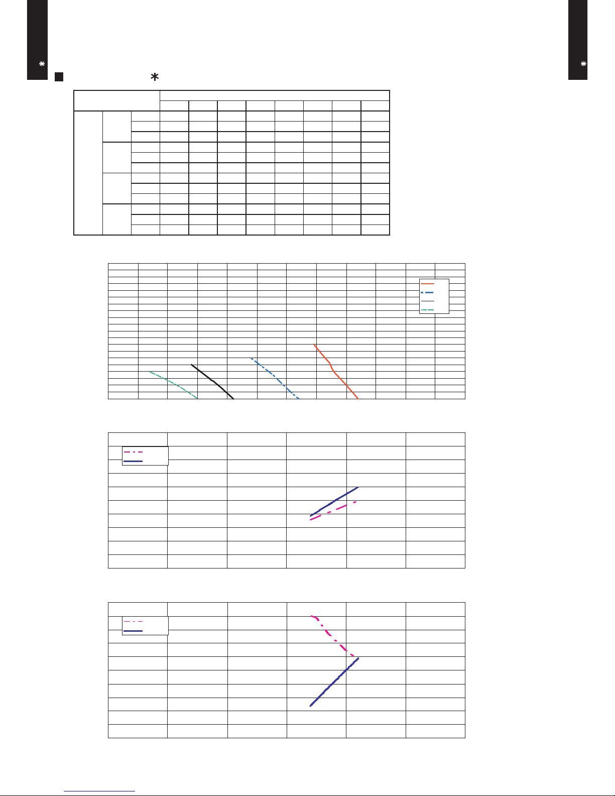
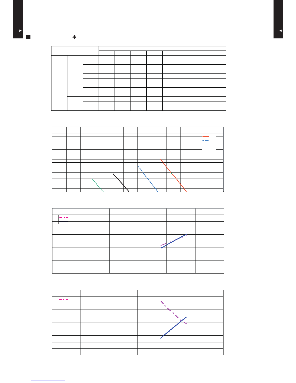
7. FAN PERFORMANCE AND CAPACITY
7-1. NORMAL MODE
Q-h Characteristic curve
Air temp
Capacity
Air temp
Capacity
Cooling capacity(%) Static pressure(Pa)Heating capacity(%)
COOLING
HEATING
Air temperature(°C)Air temperature(°C)
Air flow (m3/h)
Air flow (m3/h)
Air flow (m3/h)
Hi
Med
Low
Quiet
0 1 2 3 4 5
m3/h
720 710 700 685 670 650
l/s 200 197 194 190 186 181
CFM 424 418 412 403 394 383
m3/h
630 623 613 597 580 -
l/s 175 173 170 166 161 -
CFM 371 367 361 351 341 -
m3/h
560 553 540 520 - -
l/s 156 154 150 144 - -
CFM 330 325 318 306 - -
m3/h
480 470 450 - - -
l/s 133 131 125 - - -
CFM 283 277 265 - - -
Static pressure (Pa)
Low
Fan speed
Hi
Med
Quiet
0
5
10
15
20
400 500 600 700 800 900 1,000
94
96
98
100
102
1,000
11.0
11.5
12.0
12.5
13.0
13.5
14.0
14.5
15.0
92
94
96
98
100
102
104
106
400 500 600 700 800 900 1,000
40.0
41.0
42.0
43.0
44.0
45.0
46.0
47.0
400 500 600 700 800 900
- (01 - 13) -
MODEL : AR A12L, AR F12L
Page 15
DUCT TYPE
AR A12-14L
DUCT TYPE
AR A12-14L
MODEL : AR A14L
Q-h Characteristic curve
Air temp
Capacity
Air temp
Capacity
Cooling capacity(%) Static pressure(Pa)Heating capacity(%)
COOLING
HEATING
Air temperature(°C)Air temperature(°C)
Air flow (m3/h)
Air flow (m3/h)
Air flow (m3/h)
Hi
Med
Low
Quiet
0
5
10
15
20
94
96
98
100
102
104
0 2 3 4 5 6 7 8
m3/h
820 800 790 780 773 763 754 745
l/s 228 222 219 217 215 212 209 207
CFM 483 471 465 459 455 449 444 438
m3/h
720 693 683 670 655 640 - -
l/s 200 193 190 186 182 178 - -
CFM 424 408 402 394 386 377 - -
m3/h
610 584 570 555 540 - - -
l/s 169 162 158 154 150 - - -
CFM 359 344 335 327 318 - - -
m3/h
550 514 493 470 - - - -
l/s 153 143 137 131 - - - -
CFM 324 303 290 277 - - - -
Static pressure (Pa)
Fan speed
Hi
Med
Quiet
Low
94
96
98
100
102
104
10.0
11.0
12.0
13.0
14.0
15.0
43.0
44.0
45.0
46.0
47.0
48.0
400 500 600 700 800 900 1,000
400 500 600 700 800 900
400 500 600 700 800 900
1,000
1,000
- (01 - 14) -
Page 16
DUCT TYPE
AR A12-14L
DUCT TYPE
AR A12-14L
MODEL : AR F14L
Q-h Characteristic curve
Cooling capacity(%) Static pressure(Pa)Heating capacity(%)
HEATING
Air temperature(°C)Air temperature(°C)
Air flow (m3/h)
Air flow (m3/h)
Air flow (m3/h)
0
5
10
15
20
94
96
98
100
102
104
94
96
98
100
102
104
10.0
11.0
12.0
13.0
14.0
15.0
40.0
41.0
42.0
43.0
44.0
45.0
400 500 600 700 800 900 1,000
400 500 600 700 800 900
400 500 600 700 800 900
1,000
1,000
- (01 - 15) -
Air temp
Capacity
COOLING
0 2 3 4 5 .5 6 8 10
m 3 / h 8 7 0 85 2 84 3 8 3 4 820 81 6 79 8 78 0
l/s 24 2 23 7 2 3 4 232 22 8 2 2 7 22 2 2 1 7
C F M 5 1 2 501 49 6 49 1 48 3 4 8 0 4 7 0 45 9
m 3 / h 7 7 0 75 3 74 4 7 3 5 722 71 8 70 0 -
l/s 21 4 20 9 2 0 7 204 20 1 1 9 9 19 4 C F M 4 5 3 443 43 8 43 3 42 5 4 2 3 4 1 2 m 3 / h 6 7 0 65 0 64 0 6 3 0 615 - - -
l/s 18 6 18 1 1 7 8 175 17 1 - - C F M 3 9 4 383 37 7 37 1 36 2 - - m 3 / h 5 8 0 56 0 55 0 5 4 0 - - - -
l/s 16 1 15 6 1 5 3 150 - - - C F M 3 4 1 330 32 4 31 8 - - - -
S ta tic p r e s s u re ( P a )
FA N S P EE D
H i
M e d
Q u ie t
Lo w
Hi
Med
Low
Quiet
Air temp
Capacity
Page 17

DUCT TYPE
AR A12-14L
DUCT TYPE
AR A12-14L
MODEL : AR A12L, AR F12L
Q-h Characteristic curve
Air temp
Capacity
Air temp
Capacity
Cooling capacity(%) Static pressure(Pa)Heating capacity(%)
COOLING
Air temperature(°C)Air temperature(°C)
Air flow (m3/h)
Air flow (m3/h)
Air flow (m3/h)
Hi
Med
Low
Quiet
400 500 600 700 800 900 1,000
94
96
98
100
102
400 500 600 700 800 900 1,000
11.0
11.5
12.0
12.5
13.0
13.5
14.0
14.5
15.0
92
94
96
98
100
102
104
106
400 500 600 700 800 900 1,000
40.0
41.0
42.0
43.0
44.0
45.0
46.0
47.0
4 5 6 7 11 15 18 23
m3/h
- - - 790 760 725 700 650
l/s - - - 219 211 201 194 181
CFM - - - 465 447 427 412 383
m3/h
- - 710 700 660 615 580 -
l/s - - 197 194 183 171 161 -
CFM - - 418 412 388 362 341 -
m3/h
- 630 620 610 565 520 - -
l/s - 175 172 169 157 144 - -
CFM - 371 365 359 333 306 - -
m3/h
550 538 524 513 450 - - -
l/s 153 149 146 143 125 - - -
CFM 324 317 308 302 265 - - -
Static pressure (Pa)
Quiet
Med
Hi
Fan speed
Low
0
10
20
30
7-2. STATIC PRESSURE MODE 1
HEATING
- (01 - 16) -
Page 18

DUCT TYPE
AR A12-14L
DUCT TYPE
AR A12-14L
MODEL : AR A14L
Q-h Characteristic curve
Air temp
Capacity
Air temp
Capacity
Cooling capacity(%) Static pressure(Pa)Heating capacity(%)
COOLING
HEATING
Air temperature(°C)Air temperature(°C)
Air flow (m3/h)
Air flow (m3/h)
Air flow (m3/h)
Hi
Med
Low
Quiet
0
10
20
30
40
500 600 700 800 900 1,000
1,000
400 500 600 700 800 900 1,000
94
96
98
100
102
104
10.0
11.0
12.0
13.0
14.0
15.0
43.0
44.0
45.0
46.0
47.0
48.0
4 6 8 13 18 22 25 31
m3/h
- - - 900 854 820 795 740
l/s - - - 250 237 228 221 206
CFM - - - 530 503 483 468 436
m3/h
- - 745 695 642 595 - -
l/s - - 207 193 178 165 - -
CFM - - 438 409 378 350 - -
m3/h
- 650 630 575 520 - - -
l/s - 181 175 160 144 - - -
CFM - 383 371 338 306 - - -
m3/h
550 530 508 450 - - - -
l/s 153 147 141 125 - - - -
CFM 324 312 299 265 - - - -
Static pressure (Pa)
Quiet
Med
Hi
Fan speed
Low
94
96
98
100
102
104
400
400 500 600 700 800 900
- (01 - 17) -
Page 19

DUCT TYPE
AR A12-14L
DUCT TYPE
AR A12-14L
MODEL : AR F14L
Q-h Characteristic curve
Cooling capacity(%) Static pressure(Pa)Heating capacity(%)
COOLING
HEATING
Air temperature(°C)Air temperature(°C)
Air flow (m3/h)
Air flow (m3/h)
Air flow (m3/h)
0
10
20
30
40
500 600 700 800 900 1,000
1,000
400 500 600 700 800 900 1,000
94
96
98
100
102
104
10.0
11.0
12.0
13.0
14.0
15.0
40.0
41.0
42.0
43.0
44.0
45.0
94
96
98
100
102
104
400
400 500 600 700 800 900
- (01 - 18) -
5 8 10 13 16 1 7 21 32
m 3 / h - - - - 9 3 0 920 89 0 80 0
l/s - - - - 25 8 2 5 6 24 7 222
C F M - - - - 5 4 7 54 1 5 2 4 4 7 1
m 3 / h - - 7 8 0 7 5 0 72 3 7 1 3 6 7 5 -
l/s - - 21 7 20 8 2 0 1 1 9 8 18 8 C F M - - 4 5 9 44 1 42 6 4 2 0 397 m 3 / h - 7 0 0 6 8 0 650 62 0 61 0 - -
l/s - 1 9 4 189 18 1 17 2 16 9 - C F M - 4 1 2 4 0 0 38 3 3 6 5 3 5 9 - m 3 / h 5 9 0 56 0 54 0 - - - - -
l/s 16 4 15 6 1 5 0 - - - - C F M 3 4 7 330 31 8 - - - - -
S ta tic p r e s s u re ( P a )
Q u ie t
M e d
H i
FA N S P EE D
Lo w
Hi
Med
Low
Quiet
Air temp
Capacity
Air temp
Capacity
Page 20

DUCT TYPE
AR A12-14L
DUCT TYPE
AR A12-14L
MODEL : AR A12L, AR F12L
Q-h Characteristic curve
Air temp
Capacity
Air temp
Capacity
Cooling capacity(%) Static pressure(Pa)Heating capacity(%)
COOLING
Air temperature(°C)Air temperature(°C)
Air flow (m3/h)
Air flow (m3/h)
Air flow (m3/h)
Hi
Med
Low
Quiet
400 500 600 700 800 900 1,000
94
96
98
100
102
400 500 600 700 800 900
11.0
11.5
12.0
12.5
13.0
13.5
14.0
14.5
15.0
92
94
96
98
100
102
104
106
400 500 600 700 800 900
40.0
41.0
42.0
43.0
44.0
45.0
46.0
47.0
7-3. STATIC PRESSURE MODE 2
16 22 25 27 32 34 40 51
m3/h
- - - - - 790 745 650
l/s - - - - - 219 207 181
CFM - - - - - 465 438 383
m3/h
- - - 710 660 640 580 -
l/s - - - 197 183 178 161 -
CFM - - - 418 388 377 341 -
m3/h
- 630 600 575 520 - - -
l/s - 175 167 160 144 - - -
CFM - 371 353 338 306 - - -
m3/h
550 488 450 - - - - -
l/s 153 136 125 - - - - -
CFM 324 287 265 - - - - -
Quiet
Low
Static pressure (Pa)
Fan speed
Hi
Med
10
20
30
40
50
60
70
1,000
1,000
HEATING
- (01 - 19) -
Page 21

DUCT TYPE
AR A12-14L
DUCT TYPE
AR A12-14L
MODEL : AR A14L
Q-h Characteristic curve
Air temp
Capacity
Air temp
Capacity
Cooling capacity(%) Static pressure(Pa)Heating capacity(%)
COOLING
Air temperature(°C)Air temperature(°C)
Air flow (m3/h)
Air flow (m3/h)
Air flow (m3/h)
Hi
Med
Low
Quiet
400 500 600 700 800 900 1,000
1,000
400 500 600 700 800 900 1,000
10
20
30
40
50
60
70
20 24 28 31 36 45 53 61
m3/h
- - - - - 900 830 750
l/s - - - - - 250 231 208
CFM - - - - - 530 489 441
m3/h
- - - 745 697 610 - -
l/s - - - 207 194 169 - -
CFM - - - 438 410 359 - -
m3/h
- 635 600 570 525 - - -
l/s - 176 167 158 146 - - -
CFM - 374 353 335 309 - - -
m3/h
550 505 460 - - - - -
l/s 153 140 128 - - - - -
CFM 324 297 271 - - - - -
Low
Static pressure (Pa)
Fan speed
Hi
Med
Quiet
94
96
98
100
102
104
10.0
11.0
12.0
13.0
14.0
15.0
94
96
98
100
102
104
43.0
44.0
45.0
46.0
47.0
48.0
500 600 700 800 900400
HEATING
- (01 - 20) -
Page 22

DUCT TYPE
AR A12-14L
DUCT TYPE
AR A12-14L
MODEL : AR F14L
Q-h Characteristic curve
Cooling capacity(%) Static pressure(Pa)Heating capacity(%)
COOLING
Air temperature(°C)Air temperature(°C)
Air flow (m3/h)
Air flow (m3/h)
Air flow (m3/h)
400 500 600 700 800 900 1,000
1,000
400 500 600 700 800 900 1,000
10
20
30
40
50
60
70
94
96
98
100
102
104
10.0
11.0
12.0
13.0
14.0
15.0
94
96
98
100
102
104
40.0
41.0
42.0
43.0
44.0
45.0
500 600 700 800 900400
HEATING
- (01 - 21) -
17 23 2 4 32 36 42 46 6 1
m 3 / h - - - - - - 93 0 83 0
l/s - - - - - - 25 8 2 3 1
C F M - - - - - - 547 48 9
m 3 / h - - - 8 0 0 77 0 72 0 - -
l/s - - - 22 2 21 4 2 0 0 - C F M - - - 4 7 1 453 42 4 - m 3 / h - - 7 1 0 6 4 0 - - - -
l/s - - 19 7 17 8 - - - C F M - - 4 1 8 37 7 - - - m 3 / h 6 1 0 55 0 - - - - - -
l/s 16 9 15 3 - - - - - C F M 3 5 9 324 - - - - - -
Lo w
S ta tic p r e s s u re ( P a )
FA N S P EE D
H i
M e d
Q u ie t
Hi
Med
Low
Quiet
Air temp
Capacity
Air temp
Capacity
Page 23

DUCT TYPE
AR A12-14L
DUCT TYPE
AR A12-14L
MODEL : AR A12L, AR F12L
Q-h Characteristic curve
Air temp
Capacity
Air temp
Capacity
Cooling capacity(%) Static pressure(Pa)Heating capacity(%)
COOLING
Air temperature(°C)Air temperature(°C)
Air flow (m3/h)
Air flow (m3/h)
Air flow (m3/h)
Hi
Med
Low
Quiet
400 500 600 700 800 900 1,000
94
96
98
100
102
1,000
11.0
11.5
12.0
12.5
13.0
13.5
14.0
14.5
15.0
92
94
96
98
100
102
104
106
400 500 600 700 800 900 1,000
40.0
41.0
42.0
43.0
44.0
45.0
46.0
47.0
30
40
50
60
70
80
90
37 44 48 57 61 72 75 90
m3/h
- - - - - - 790 650
l/s - - - - - - 219 181
CFM - - - - - - 465 383
m3/h
- - - - 710 580 - -
l/s - - - - 197 161 - -
CFM - - - - 418 341 - -
m3/h
- - 630 520 - - - -
l/s - - 175 144 - - - -
CFM - - 371 306 - - - -
m3/h
550 450 - - - - - -
l/s 153 125 - - - - - -
CFM 324 265 - - - - - -
Quiet
Med
Hi
Fan speed
Low
Static pressure (Pa)
7-4. STATIC PRESSURE MODE 3
400 500 600 700 800 900
HEATING
- (01 - 22) -
Page 24

DUCT TYPE
AR A12-14L
DUCT TYPE
AR A12-14L
MODEL : AR A14L
Q-h Characteristic curve
Air temp
Capacity
Air temp
Capacity
Cooling capacity(%) Static pressure(Pa)Heating capacity(%)
COOLING
Air temperature(°C)Air temperature(°C)
Air flow (m3/h)
Air flow (m3/h)
Air flow (m3/h)
Hi
Med
Low
Quiet
400 500 600 700 800 900 1,000
1,000
400 500 600 700 800 900 1,000
94
96
98
100
102
104
10.0
11.0
12.0
13.0
14.0
15.0
94
96
98
100
102
104
43.0
44.0
45.0
46.0
47.0
48.0
38 42 46 52 57 65 76 90
m3/h
- - - - - - 900 770
l/s - - - - - - 250 214
CFM - - - - - - 530 453
m3/h
- - - - 710 620 - -
l/s - - - - 197 172 - -
CFM - - - - 418 365 - -
m3/h
- - 610 530 - - - -
l/s - - 169 147 - - - -
CFM - - 359 312 - - - -
m3/h
525 475 - - - - - -
l/s 146 132 - - - - - -
CFM 309 280 - - - - - -
Med
Hi
Fan speed
Low
Static pressure (Pa)
Quiet
30
40
50
60
70
80
90
400 500 600 700 800 900
HEATING
- (01 - 23) -
Page 25

DUCT TYPE
AR A12-14L
DUCT TYPE
AR A12-14L
MODEL : AR F14L
Q-h Characteristic curve
Cooling capacity(%) Static pressure(Pa)Heating capacity(%)
COOLING
Air temperature(°C)Air temperature(°C)
Air flow (m3/h)
Air flow (m3/h)
Air flow (m3/h)
400 500 600 700 800 900 1,000
1,000
400 500 600 700 800 900 1,000
94
96
98
100
102
104
10.0
11.0
12.0
13.0
14.0
15.0
94
96
98
100
102
104
40.0
41.0
42.0
43.0
44.0
45.0
30
20
40
50
60
70
80
90
400 500 600 700 800 900
HEATING
- (01 - 24) -
29 35 4 2 51 55 65 77 9 0
m 3 / h - - - - - - 92 0 83 0
l/s - - - - - - 25 6 2 3 1
C F M - - - - - - 541 48 9
m 3 / h - - - - 8 0 0 730 - -
l/s - - - - 22 2 2 0 3 - C F M - - - - 4 7 1 43 0 - m 3 / h - - 7 2 0 6 5 5 - - - -
l/s - - 20 0 18 2 - - - C F M - - 4 2 4 38 6 - - - m 3 / h 6 1 0 56 0 - - - - - -
l/s 16 9 15 6 - - - - - C F M 3 5 9 330 - - - - - -
M e d
H i
FA N S P EE D
Lo w
S ta tic p r e s s u re ( P a )
Q u ie t
Hi
Med
Low
Quiet
Air temp
Capacity
Air temp
Capacity
Page 26

DUCT TYPE
AR A12-14L
DUCT TYPE
AR A12-14L
8-1. NOISE LEVEL CURVE
8. OPERATION NOISE
COOLING
Octave band sound pressure level, dB:(0dB=0.0002µbar)
Octave band center frequency,Hz
0
10
20
30
40
50
60
70
80
Octave band sound pressure level, dB:(0dB=0.0002µbar)
Octave band center frequency,Hz
0
10
20
30
40
50
60
70
80
Octave band sound pressure level, dB:(0dB=0.0002µbar)
0
10
20
30
40
50
60
70
80
63 125 250 500 1,000 2,000 4,000 8,000
Octave band center frequency,Hz
63 125 250 500 1,000 2,000 4,000 8,000
63 125 250 500 1,000 2,000 4,000 8,000
HEATING
COOLING
HEATING
Octave band sound pressure level, dB:(0dB=0.0002µbar)
Octave band center frequency,Hz
0
10
20
30
40
50
60
70
80
63 125 250 500 1,000 2,000 4,000 8,000
MODEL : AR A12L, AR F12L
Condition
Static pressure : 0Pa
Static mode : Normal
HIGH
QUIET
NC-20
NC-40
NC-50
NC-60
NC-30
NC-15
NC-25
NC-35
NC-45
NC-55
NC-65
NC-20
NC-40
NC-50
NC-60
NC-30
NC-15
NC-25
NC-35
NC-45
NC-55
NC-65
HIGH
QUIET
NC-20
NC-40
NC-50
NC-60
NC-30
NC-15
NC-25
NC-35
NC-45
NC-55
NC-65
HIGH
QUIET
NC-20
NC-40
NC-50
NC-60
NC-30
NC-15
NC-25
NC-35
NC-45
NC-55
NC-65
HIGH
QUIET
MODEL : AR A14L, AR F14L
- (01 - 25) -
Page 27

DUCT TYPE
AR A12-14L
DUCT TYPE
AR A12-14L
8-2. SOUND LEVEL CHECK POINT
Microphone Microphone
Measuring duct
Measuring duct
- (01 - 26) -
Page 28

DUCT TYPE
AR A12-14L
DUCT TYPE
AR A12-14L
9. ELECTRIC CHARACTERISTICS
Model name
AR A12L
AR F12L
AR A14L
AR F14L
Voltage V
Frequency Hz
Max. operating current (Indoor unit) A 0.3 0.5
Connection cable
mm
2
Limited wiring length m
26
Wiring spec.
(Indoor unit to outdoor unit)
Power supply
230
50
1.5 - 2.5
- (01 - 27) -
Page 29

DUCT TYPE
AR A12-14L
DUCT TYPE
AR A12-14L
10. SAFETY DEVICES
AR A12L
AR F12L
AR A14L
AR F14L
Circuit protection Current fuse (PCB)
Fan motor protection Thermal protection program
3.15A 250V
140±20°C OFF
110±20°C ON
Protection form
Model
- (01 - 28) -
Page 30

DUCT TYPE
AR A12-14L
DUCT TYPE
AR A12-14L
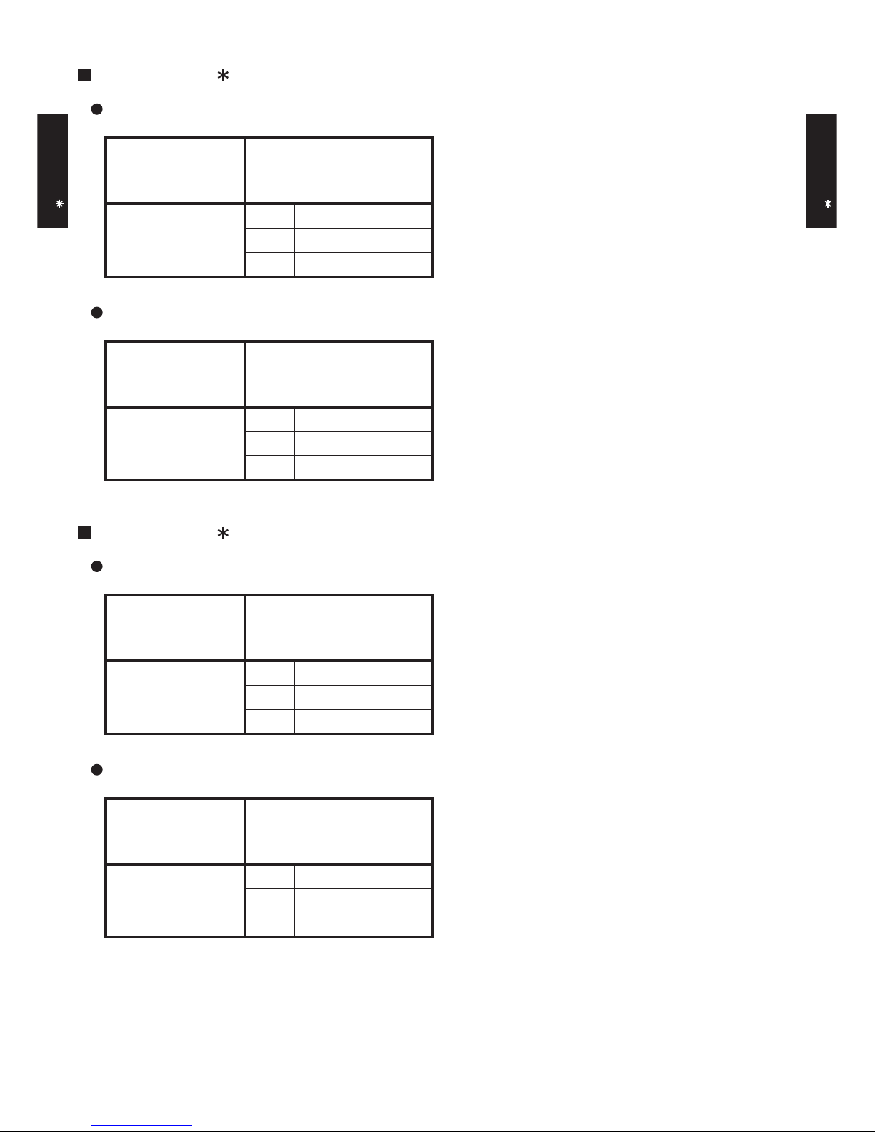
11. OPTIONAL PARTS
Exterior Summary
Parts name
Remote Sensor
IR Receiver
unit
Drain pump
unit
External
control set
Model No.
UTD-RS100
UTD-ECS5A
UTZ-PX1BBA
UTY-LRH 1
New amenity space can be
offered by installing the
Remote sensor in the remote
controller.
Use to connect with various
peripheral devices and air
conditioner PC board.
- (01 - 29) -
Unit control is performed by
wireless remote controller.
Optional drain lift up
mechanism allows more
flexible installation.
Page 31

AO A12LACL
AO A12LALL
R410A
D2D_AO010E/03
2008.04.08
2.
SINGLE TYPE :
OUTDOOR UNIT
AO A14LACL
AO A14LALL
Page 32

OUTDOOR UNIT
AO A12-14L
OUTDOOR UNIT
AO A12-14L
1. SPECIFICATIONS
AO A12LACL AO A14LACL
AO A12LALL AO A14LALL
A 4.9 5.9
1780 1910
1630 1740
W
47 49
48 49
W
g 1150 1250
40 (88) 40 (88)
44 (97) 44 (97)
Φ
9.52 (Φ 3/8 in.)
Φ
12.70 (Φ 1/2 in.)
Note :
Specifications are based on the following conditions.
Cooling : Indoor temperature of 27°CDB/19°CWB. and outdoor temperature of 35°CDB/24°CWB.
Heating : Indoor temperature of 20°CDB/15°CWB. and outdoor temperature of 7°CDB/6°CWB.
Pipe length : 7.5 m, Height difference : 0 m. (Outdoor unit - Indoor unit)
Cooling
Heating
Type
Gross
Liquid
Gas
Method
Colour
Net
Gross
Net
Motor output
Type
Charge
Material
Rows x Stages
Pipe type
Fin type
Type × Q'ty
Motor output
Cooling
Heating
Dimensions (H × W × D)
Type
Model name
Power source
Available voltage range
578 × 790 × 300
25 (chargeless : 15)
15
546 × 876 × 18.2
546 × 842 × 18.2
1.30
2 × 26
Copper
Aluminium
Steel sheet
Beige (10YR7.5/1.0NN)
54
°COperation range
Fan
Airflow
rate
m3/h
dB(A)
mm
mm
Weight kg(lb.)
Dimensions
(H × W × D)
Refrigerant oil
Enclosure
Heat exchanger type
Fin pitch
Compressor
Refrigerant
Sound pressure level
Starting current
Cooling
Heating
Type × Q'ty
m
Connection pipe
Size mm
Max. length
Max. height difference
INVERTER HEATPUMP
230V 50Hz
198-264V 50Hz
Propeller × 1
Twin Rotary × 1
1100
R410A
POE
Flare
-10 to 46
-15 to 24
648 × 910 × 380
Φ
6.35 (Φ 1/4 in.)
- (02 - 01) -
Page 33

OUTDOOR UNIT
AO A12-14L
OUTDOOR UNIT
AO A12-14L
2. DIMENSIONS
MODEL : AO A12L, AO A14L
(Unit : mm)
Air flow
Top view
When there are obstacles at the
back or front sides.
When there are obstacles at the
back, side(s), and top.
600 or more
250 or more
250 or more
300 or more
600 - 1000
100 or more
300 or more
100 - 300
250 or more
(Service space)
MOUNTING POSITION
Front view
Side view
Bottom view
If the space is larger that is stated, the condition will be the same as that are no obstacles.
- (02 - 02) -
When there are obstacles at the
back, side with the installation of
more than one unit.
Page 34

OUTDOOR UNIT
AO A12-14L
OUTDOOR UNIT
AO A12-14L
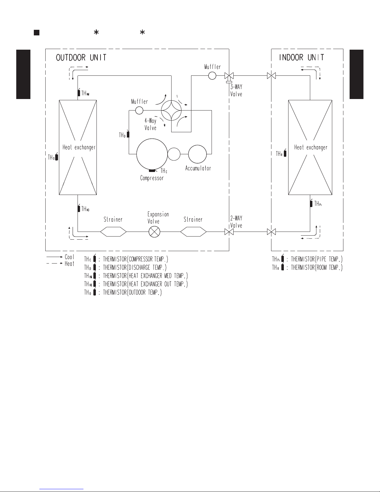
3. REFRIGERANT CIRCUIT
MODEL : AO A12L, AO A14L
- (02 - 03) -
Page 35

OUTDOOR UNIT
AO A12-14L
OUTDOOR UNIT
AO A12-14L
MODEL : AO A12L, AO A14L
4. WIRING DIAGRAMS
- (02 - 04) -
Page 36

OUTDOOR UNIT
AO A12-14L
OUTDOOR UNIT
AO A12-14L
5. CAPACITY COMPENSATION RATE FOR PIPE LENGTH
AND HEIGHT DIFFERENCE
MODEL : AO A12L
Indoor unit
Height difference H
Connection pipe
H
Outdoor unit
Indoor unit
Connection pipe
H
Outdoor unit
Indoor unit is upper than outdoor unit.
1
Indoor unit is under than outdoor unit.
2
5 7.5 10 15 20 25
15 - - -
0.933 0.923 0.895
10 - -
0.980 0.933 0.923 0.895
7.5 -
1.000 0.980 0.933 0.923 0.895
5
1.026 1.000 0.980 0.933 0.923 0.895
0 1.026 1.000 0.980 0.933 0.923 0.895
-5
1.018 0.992 0.972 0.925 0.916 0.888
-7.5 -
0.988 0.968 0.922 0.912 0.885
-10 - -
0.964 0.918 0.909 0.881
-15 - - -
0.903 0.894 0.867
5 7.5 10 15 20 25
15 - - -
0.925 0.898 0.878
10 - -
0.999 0.934 0.907 0.887
7.5 -
0.993 1.002 0.936 0.909 0.890
5
0.949 0.995 1.005 0.939 0.912 0.892
0 0.954 1.000 1.010 0.943 0.916 0.896
-5
0.954 1.000 1.010 0.943 0.916 0.896
-7.5 -
1.000 1.010 0.943 0.916 0.896
-10 - -
1.010 0.943 0.916 0.896
-15 - - -
0.943 0.916 0.896
Height
difference H
(m)
1
Indoor unit is upper
than outdoor unit.
2
Indoor unit is under
than outdoor unit
Pipe length (m)
Pipe length (m)
HEATING
COOLING
1
Indoor unit is upper
than outdoor unit.
2
Indoor unit is under
than outdoor unit
Height
difference H
(m)
This table is created using the maximum capacity.
- (02 - 05) -
Page 37

OUTDOOR UNIT
AO A12-14L
OUTDOOR UNIT
AO A12-14L
MODEL : AO A14L
Indoor unit
Height difference H
Connection pipe
H
Outdoor unit
Indoor unit
Connection pipe
H
Outdoor unit
Indoor unit is upper than outdoor unit.1 Indoor unit is under than outdoor unit.2
5 7.5 10 15 20 25
15 - - -
0.984 0.982 0.978
10 - -
0.999 0.984 0.982 0.978
7.5 -
1.000 0.999 0.984 0.982 0.978
5
1.000 1.000 0.999 0.984 0.982 0.978
0 1.000 1.000 0.999 0.984 0.982 0.978
-5
0.992 0.992 0.991 0.976 0.974 0.970
-7.5 -
0.988 0.987 0.972 0.970 0.966
-10 - -
0.983 0.968 0.966 0.962
-15 - - -
0.953 0.950 0.947
5 7.5 10 15 20 25
15 - - -
0.900 0.873 0.845
10 - -
0.972 0.909 0.882 0.854
7.5 -
0.993 0.974 0.912 0.884 0.856
5
0.989 0.995 0.976 0.914 0.886 0.858
0 0.994 1.000 0.981 0.918 0.891 0.862
-5
0.994 1.000 0.981 0.918 0.891 0.862
-7.5 -
1.000 0.981 0.918 0.891 0.862
-10 - -
0.981 0.918 0.891 0.862
-15 - - -
0.918 0.891 0.862
HEATING
COOLING
1
Indoor unit is upper
than outdoor unit.
2
Indoor unit is under
than outdoor unit
Height
difference H
(m)
Pipe length (m)
Pipe length (m)
Height
difference H
(m)
1
Indoor unit is upper
than outdoor unit.
2
Indoor unit is under
than outdoor unit
This table is created using the maximum capacity.
- (02 - 06) -
Page 38

OUTDOOR UNIT
AO A12-14L
OUTDOOR UNIT
AO A12-14L
6. ADDITIONAL CHARGE CALCULATION
MODEL : AO A12L
REFRIGERANT CHARGE
MODEL : AO A14L
REFRIGERANT CHARGE
Refrigerant amount g
Pipe length m 15 20 25
Additional charge g 0 (Chargeless) +100 +200
Refrigerant amount g
Pipe length m 15 20 25
Additional charge g 0 (Chargeless) +100 +200
Refrigerant type
Refrigerant type
20g/m
1250
R410A
1150
20g/m
R410A
- (02 - 07) -
Page 39
OUTDOOR UNIT
AO A12-14L
OUTDOOR UNIT
AO A12-14L
MODEL : AO A12L
7. AIR FLOW
COOLING
HEATING
MODEL : AO A14L
COOLING
HEATING
m3/h
1780
l/s 494
CFM 1048
m3/h
1630
l/s 453
CFM 959
m3/h
1910
l/s 531
CFM 1124
m3/h
1740
l/s 483
CFM 1024
750
820
700
770
Number of
rotations
(r.p.m)
(r.p.m)
(r.p.m)
(r.p.m)
Air flow
Number of
rotations Air flow
Number of
rotations Air flow
Number of
rotations Air flow
- (02 - 08) -
Page 40

OUTDOOR UNIT
AO A12-14L
OUTDOOR UNIT
AO A12-14L
- (02 - 09) -
8-1. NOISE LEVEL CURVE
MODEL : AO A12L
O
c
t
ave ban
d
sou
n
d pressure level, dB:(0dB=0.0002µbar)
Octave band center frequency,Hz
0
10
20
30
40
50
60
70
80
63 125 250 50 0 1,000 2,000 4,000 8,000
O
c
t
ave ban
d
sou
n
d pressure level, dB:(0dB=0.0002µbar)
Octave band center frequency,Hz
0
10
20
30
40
50
60
70
80
63 125 250 50 0 1,000 2,000 4,000 8,000
MODEL : AO A14L
8. OPERATION NOISE
COOLING
Octave band sound pressure level,
d
B:(0dB=0.000
2
µb
ar
)
Octave band center frequency,Hz
0
10
20
30
40
50
60
70
80
63 125 250 50 0 1,000 2,000 4,000 8,000
MODEL : AO A12L
Octave band sound pressure level, dB:(0dB=0.0002µbar)
Octave band center frequency,Hz
0
10
20
30
40
50
60
70
80
63 125 250 50 0 1,000 2,000 4,000 8,000
MODEL : AO A14L
HEATING
NC-20
NC-40
NC-50
NC-60
NC-30
NC-15
NC-25
NC-35
NC-45
NC-55
NC-65
NC-20
NC-40
NC-50
NC-60
NC-30
NC-15
NC-25
NC-35
NC-45
NC-55
NC-65
NC-20
NC-40
NC-50
NC-60
NC-30
NC-15
NC-25
NC-35
NC-45
NC-55
NC-65
NC-20
NC-40
NC-50
NC-60
NC-30
NC-15
NC-25
NC-35
NC-45
NC-55
NC-65
Page 41

OUTDOOR UNIT
AO A12-14L
OUTDOOR UNIT
AO A12-14L
8-2. SOUND LEVEL CHECK POINT
- (02 - 10) -
Page 42

OUTDOOR UNIT
AO A12-14L
OUTDOOR UNIT
AO A12-14L
9. ELECTRIC CHARACTERISTICS
AO A12L AO A14L
Voltage V
Frequency Hz
A 10.0 12.5
A 4.9 5.9
Main Fuse (Circuit breaker)
Current
A 20 20
Power Cable
mm
2
*2) Limited wiring length m 36 28
*1) Wiring Spec.
Selected Sample
(Selected based on Japan Electrotechnical Standard and Codes Committee E0005)
*2) Limited Wiring length
This is the wiring length in case voltage descent is less than 2%.
When the wiring length becomes long, please select the wiring of a more larger diameter.
Model Name
Max Operating Current
Starting Current
Power Supply
*1) Wiring Spec.
230
50
4.0
- (02 - 11) -
Page 43

OUTDOOR UNIT
AO A12-14L
OUTDOOR UNIT
AO A12-14L
10. SAFETY DEVICES
AO A12L AO A14L
Fan motor protection Thermal protection program
Thermal protection program
(COMPRESSOR TEMP.)
Thermal protection program
(DISCHARGE TEMP.)
15A 250V
3.15A 250V
Compressor protection
Circuit protection
OFF : 110°C
ON : After 40 minutes
OFF : 110°C
ON : After 7 minutes
Current fuse (NEAR THE TERMINAL)
Current fuse
(MAIN PRINTED CIRCUIT BOARD)
OFF : 100
+15
-10
°C
ON : 95
+15
-10
°C
Protection form
20A 250V
5A 250V
Model
- (02 - 12) -
Page 44
AO B12LACL
AO B12LALL
R410A
D2D_AO020E/02
2008.04.08
2.
SINGLE TYPE :
OUTDOOR UNIT
AO B14LACL
AO B14LALL
Page 45

- (02 - 01) -
OUTDOOR UNIT
AOB12-14L
OUTDOOR UNIT
AOB12-14L
1. SPECIFICATIONS
Note :
Specifications are based on the following conditions.
Cooling : Indoor temperature of 27°CDB/19°CWB. and outdoor temperature of 35°CDB/24°CWB.
Heating : Indoor temperature of 20°CDB/15°CWB. and outdoor temperature of 7°CDB/6°CWB.
Pipe length : 7.5 m, Height difference : 0 m. (Outdoor unit - Indoor unit)
Power source
Available voltage range
A 4.9 5.9
Cooling 1780 1910
Heating 1630 1740
Type × Q'ty
Motor output W
Cooling 47 49
Heating 48 49
Dimensions (H × W × D)
Fin pitch
Rows x Stages
Pipe type
Fin type
Motor output W
Charge g 1150 1250
Material
Colour
Net
Gross
Net 40 ( 88 ) 40 ( 88 )
Gross 44 ( 97 ) 44 ( 97 )
Liquid
Gas
Φ 9.52 (Φ 3/8 in.) Φ
12.70 (Φ 1/2 in.)
Method
Max. length
Max. height difference
Cooling
Heating
578 × 790 × 300
25(chargeless:15)
15
546 × 876 × 18.2
546 × 842 × 18.2
1.30
2 × 26
Copper
Aluminium
Steel sheet
Beige (10YR7.5/1.0NN)
54
°COperation range
Type
Model name
Fan
Airflow
rate
m3/h
dB(A)
mm
mm
Weight kg(lb.)
Dimensions
( H×W×D)
Refrigerant oil Type
Enclosure
Heat exchanger type
Starting current
Compressor
Type × Q'ty
Refrigerant
Type
Sound pressure level
m
Connection pipe
Size mm
INVERTER HEATPUMP
230V ~50Hz
198-264V ~ 50Hz
Propeller × 1
Twin Rotary × 1
1100
R410A
POE
Flare
-10 to 46
-15 to 24
648 × 910 × 380
Φ
6.35 (Φ 1/4 in.)
AO B12LACL AO B14LACL
AO B12LALL AO B14LALL
Page 46

- (02 - 02) -
OUTDOOR UNIT
AOB12-14L
OUTDOOR UNIT
AOB12-14L
2. DIMENSIONS
MODEL : AO B12L, AO B14L
(Unit : mm)
Air flow
Top view
When there are obstacles at the
back or front sides.
When there are obstacles at the
back, side(s), and top.
When there are obstacles at the
back, side with the installation of
more than one unit.
600 or more
250 or more
250 or more
300 or more
600 - 1000
100 or more
300 or more
100 - 300
250 or more
(Service space)
MOUNTING POSITION
Front view
Side view
Bottom view
If the space is larger that is stated, the condition will be the same as that are no obstacles.
Page 47
- (02 - 03) -
OUTDOOR UNIT
AOB12-14L
OUTDOOR UNIT
AOB12-14L
3. REFRIGERANT CIRCUIT
MODEL : AO B12L, AO B14L
Page 48

- (02 - 04) -
OUTDOOR UNIT
AOB12-14L
OUTDOOR UNIT
AOB12-14L
MODEL : AO B12L, AO B14L
4. WIRING DIAGRAMS
Page 49

- (02 - 05) -
OUTDOOR UNIT
AOB12-14L
OUTDOOR UNIT
AOB12-14L
5. CAPACITY COMPENSATION RATE FOR PIPE LENGTH
AND HEIGHT DIFFERENCE
MODEL : AO B12L
Indoor unit
Height difference H
Connection pipe
H
Outdoor unit
Indoor unit
Connection pipe
H
Outdoor unit
Indoor unit is upper than outdoor unit.
1
Indoor unit is under than outdoor unit.
2
5 7.5 10 15 20 25
15 - - -
0.933 0.923 0.895
10 - -
0.980 0.933 0.923 0.895
7.5 -
1.000 0.980 0.933 0.923 0.895
5
1.026 1.000 0.980 0.933 0.923 0.895
0 1.026 1.000 0.980 0.933 0.923 0.895
-5
1.018 0.992 0.972 0.925 0.916 0.888
-7.5 -
0.988 0.968 0.922 0.912 0.885
-10 - -
0.964 0.918 0.909 0.881
-15 - - -
0.903 0.894 0.867
5 7.5 10 15 20 25
15 - - -
0.925 0.898 0.878
10 - -
0.999 0.934 0.907 0.887
7.5 -
0.993 1.002 0.936 0.909 0.890
5
0.949 0.995 1.005 0.939 0.912 0.892
0 0.954 1.000 1.010 0.943 0.916 0.896
-5
0.954 1.000 1.010 0.943 0.916 0.896
-7.5 -
1.000 1.010 0.943 0.916 0.896
-10 - -
1.010 0.943 0.916 0.896
-15 - - -
0.943 0.916 0.896
Height
difference H
(m)
1
Indoor unit is upper
than outdoor unit.
2
Indoor unit is under
than outdoor unit
Pipe length (m)
Pipe length (m)
HEATING
COOLING
1
Indoor unit is upper
than outdoor unit.
2
Indoor unit is under
than outdoor unit
Height
difference H
(m)
Page 50

- (02 - 06) -
OUTDOOR UNIT
AOB12-14L
OUTDOOR UNIT
AOB12-14L
MODEL : AO B14L
Indoor unit
Height difference H
Connection pipe
H
Outdoor unit
Indoor unit
Connection pipe
H
Outdoor unit
Indoor unit is upper than outdoor unit.1 Indoor unit is under than outdoor unit.2
5 7.5 10 15 20 25
15 - - -
0.984 0.982 0.978
10 - -
0.999 0.984 0.982 0.978
7.5 -
1.000 0.999 0.984 0.982 0.978
5
1.000 1.000 0.999 0.984 0.982 0.978
0 1.000 1.000 0.999 0.984 0.982 0.978
-5
0.992 0.992 0.991 0.976 0.974 0.970
-7.5 -
0.988 0.987 0.972 0.970 0.966
-10 - -
0.983 0.968 0.966 0.962
-15 - - -
0.953 0.950 0.947
5 7.5 10 15 20 25
15 - - -
0.900 0.873 0.845
10 - -
0.972 0.909 0.882 0.854
7.5 -
0.993 0.974 0.912 0.884 0.856
5
0.989 0.995 0.976 0.914 0.886 0.858
0 0.994 1.000 0.981 0.918 0.891 0.862
-5
0.994 1.000 0.981 0.918 0.891 0.862
-7.5 -
1.000 0.981 0.918 0.891 0.862
-10 - -
0.981 0.918 0.891 0.862
-15 - - -
0.918 0.891 0.862
HEATING
COOLING
1
Indoor unit is upper
than outdoor unit.
2
Indoor unit is under
than outdoor unit
Height
difference H
(m)
Pipe length (m)
Pipe length (m)
Height
difference H
(m)
1
Indoor unit is upper
than outdoor unit.
2
Indoor unit is under
than outdoor unit
Page 51

- (02 - 07) -
OUTDOOR UNIT
AOB12-14L
OUTDOOR UNIT
AOB12-14L
6. ADDITIONAL CHARGE CALCULATION
MODEL : AO B12L
REFRIGERANT CHARGE
MODEL : AO B14L
REFRIGERANT CHARGE
Refrigerant amount g
Pipe length m 15 20 25
Additional charge g 0 (Chargeless) +100 +200
Refrigerant amount g
Pipe length m 15 20 25
Additional charge g 0 (Chargeless) +100 +200
Refrigerant type
Refrigerant type
20g/m
1250
R410A
1150
20g/m
R410A
Page 52

- (02 - 08) -
OUTDOOR UNIT
AOB12-14L
OUTDOOR UNIT
AOB12-14L
MODEL : AO B12L
7. AIR FLOW
COOLING
HEATING
MODEL : AO B14L
COOLING
HEATING
m3/h
1780
l/s 494
CFM 1048
m3/h
1630
l/s 453
CFM 959
m3/h
1910
l/s 531
CFM 1124
m3/h
1740
l/s 483
CFM 1024
750
820
700
770
Number of
rotations
(r.p.m)
(r.p.m)
(r.p.m)
(r.p.m)
Air flow
Number of
rotations Air flow
Number of
rotations Air flow
Number of
rotations Air flow
Page 53

- (02 - 09) -
OUTDOOR UNIT
AOB12-14L
OUTDOOR UNIT
AOB12-14L
8-1. NOISE LEVEL CURVE
COOLING
HEATING
8. OPERATION NOISE
MODEL : AO B12L
COOLING HEATING
MODEL : AO B14L
Octave band sound pressure level, dB:(0dB=0.0002µbar)
Octave band center frequency,Hz
0
10
20
30
40
50
60
70
80
63 125 250 50 0 1,000 2,000 4,000 8,000
NC-20
NC-40
NC-50
NC-60
NC-30
NC-15
NC-25
NC-35
NC-45
NC-55
NC-65
Octave band sound pressure level, dB:(0dB=0.0002µbar)
Octave band center frequency,Hz
0
10
20
30
40
50
60
70
80
63 125 250 50 0 1,000 2,000 4,000 8,000
NC-20
NC-40
NC-50
NC-60
NC-30
NC-15
NC-25
NC-35
NC-45
NC-55
NC-65
Octave band sound pressure level, dB:(0dB=0.0002µbar)
Octave band center frequency,Hz
0
10
20
30
40
50
60
70
80
63 125 250 50 0 1,000 2,000 4,000 8,000
NC-20
NC-40
NC-50
NC-60
NC-30
NC-15
NC-25
NC-35
NC-45
NC-55
NC-65
Octave band sound pressure level, dB:(0dB=0.0002µbar)
Octave band center frequency,Hz
0
10
20
30
40
50
60
70
80
63 125 250 50 0 1,000 2,000 4,000 8,000
NC-20
NC-40
NC-50
NC-60
NC-30
NC-15
NC-25
NC-35
NC-45
NC-55
NC-65
Page 54

- (02 - 10) -
OUTDOOR UNIT
AOB12-14L
OUTDOOR UNIT
AOB12-14L
8-2. SOUND LEVEL CHECK POINT
Page 55

- (02 - 11) -
OUTDOOR UNIT
AOB12-14L
OUTDOOR UNIT
AOB12-14L
9. ELECTRIC CHARACTERISTICS
*1) Wiring spec.
Selected sample
(Selected based on Japan Electrotechnical Standard and Codes Committee E0005)
*2) Limited wiring length
This is the wiring length in case voltage descent is less than 2%.
When the wiring length becomes long, please select the wiring of a more larger diameter.
Model name AO B12L AO B14L
Voltage V
Frequency Hz
Max. operating current A 10.0 12.5
Starting current A 4.9 5.9
Main fuse (Circuit breaker)
current
A 20 20
Power cable mm
2
*2)Limited wiring length m 36 28
Power supply
*1) Wiring spec.
230
~
50
4.0
Page 56

- (02 - 12) -
OUTDOOR UNIT
AOB12-14L
OUTDOOR UNIT
AOB12-14L
10. SAFETY DEVICES
AO B12L AO B14L
Fan motor protection Thermal protection program
Thermal protection program
(COMPRESSOR TEMP.)
Thermal protection program
(DISCHARGE TEMP.)
15A 250V
3.15A 250V
Compressor protection
Circuit protection
OFF : 110°C
ON : After 40 minutes
OFF : 110°C
ON : After 7 minutes
Current fuse (NEAR THE TERMINAL)
Current fuse
(MAIN PRINTED CIRCUIT BOARD)
OFF : 100
+15
-10
°C
ON : 95
+15
-10
°C
Protection form
20A 250V
5A 250V
Model
 Loading...