

Page 1
DESIGN & TECHNICAL MANUAL
SINGLE
INDOOR
OUTDOOR
AOA72LALT
AO
A90LALT
AR
C72LHTA ARC90LHTA
AIR CONDITIONER
Duct type
Page 2

1. INDOOR UNIT
DTR_AR061E_03
2013.11.08
DUCT TYPE :
ARC72LHTA
ARC90LH TA
Page 3

DUCT TYPE
AR
C72-90LHTA
DUCT TYPE
AR
C72-90LHTA
CONTENTS
1. INDOOR UNIT
1. FEATURES
........................................................................................................ 01 - 01
2. WIRED REMOTE CONTROLLER
................................................... 01 - 06
3. SPECIFICATIONS
........................................................................................ 01 - 08
4. DIMENSIONS
................................................................................................... 01 - 09
5. WIRING DIAGRAMS
.................................................................................. 01 - 12
6. CAPACITY TABLE
....................................................................................... 01 - 13
6-1. COOLING CAPACITY
................................................................................ 01 - 13
6-2. HEATING CAPACITY
................................................................................. 01 - 14
7. FAN PERFORMANCE AND CAPACITY
..................................... 01 - 15
8. OPERATION NOISE
................................................................................... 01 - 19
8-1. NOISE LEVEL CURVE
............................................................................... 01 - 19
8-2. SOUND LEVEL CHECK POINT
............................................................... 01 - 20
9. ELECTRIC CHARACTERISTICS
..................................................... 01 - 21
10. SAFETY DEVICES
....................................................................................... 01 - 22
11. EXTERNAL INPUT & OUTPUT
......................................................... 01 - 23
11-1. EXTERNAL INPUT
...................................................................................... 01 - 23
11-2. EXTERNAL OUTPUT
................................................................................. 01 - 24
12. FUNCTION SETTINGS
............................................................................. 01 - 29
12-1. INDOOR UNIT
.............................................................................................. 01 - 29
12-2. INDOOR UNIT (Setting by remote controller)
..................................... 01 - 31
12-3. WIRED REMOTE CONTROLLER
............................................................ 01 - 34
13. OPTIONAL PARTS
...................................................................................... 01 - 35
13-1. CONTROLLER
............................................................................................ 01 - 35
13-2. OTHERS
....................................................................................................... 01 - 35
Page 4

- (01 - 01) -
DUCT TYPE
AR
C72-90LHTA
DUCT TYPE
AR
C72-90LHTA
FEATUR ES1.
MODEL
ARC72LHTA / AOA72LALT
ARC90LHTA / AOA9 0 L ALT
FEATURES
Signicantly improved EER/COP
z
Signicantly improved Hi-efciency is realized by the use of a ALL-DC components, inverter
technology, and large heat exchanger.
Energy saving technology
z
OUTDOOR UNIT
INDOOR UNIT
Previous
model
Cooling Heating
New
model
EER2.0 3.00.0
Cooling EER
57%inc rease!
!
2.03
3.20
2.0 3.00.0 COP
Heat ing COP
44%increase !
2.36
3.40
(AR¾C90L) (AR¾C90L)
Surface area
1.7times!
New model
Power consumption
has been reduced
by 25% compared to
previous models by
using a compact and
high performance DC
fan motor.
High efciency
operation is
realized by
using a sine
wave DC
inverter control.
Signicantly
greater efciency
is realized by
use of a large
capacity DC twin
rotary compressor
with substantially
increased
refrigerant intake
and compression
ef ci ency.
Heat exchange ef ciency is signicantly
improved by the introduction of a new
4-face heat exchanger that increases
effective surface area.
In multiple outdoor unit installations, the
unique front intake design improves air ow
into the Heat exchanger.
Previous
model
ARC72LHTA
ARC9 0LHTA
The power consumption has
been reduced drastically by the
introduction of DC fan motors.
Page 5

- (01 - 02) -
DUCT TYPE
AR
C72-90LHTA
DUCT TYPE
AR
C72-90LHTA
Space saving and compact size
z
Compact size has been achieved by signicantly reducing the width of the outdoor units
compared to previous models.
Static pressure selection
z
5 Static Pressure modes are available.
Improvement and design exibility has allowed multiple fan speeds and static pressure modes.
The air ow rate has been improved to meet the requirements of complex ductwork layout designs. •
→ By introducing a new DC fan motor, the static pressure range selected by the installer can
range between 50 to 250Pa.
A three speed fan (High, Medium and Low) allows accurate airow control. •
A decrease in the power consumption of the indoor unit has been realised by optimizing the •
control of the indoor fan motor rotation frequency.
Low static pressure - High static pressure
Fan motor speed : Low speed - High speed
3900
0
50
100
150
200
250
300
4100 4300 4500 4700 4900 5100 5300 5500
Normal (72Pa)
LSP mode (50Pa)
HSP mode 1 (150Pa)
HSP mode 2 (200Pa)
HSP mode 3 (250Pa)
Static pressure (Pa)
Air flow (m3/h)
Max. 250Pa
Rating
(AR¾C90L)
]
Efciency of the indoor unit operation has
been improved in both the static pressure and
air ow design.
1,300
930
28%
reduction
Previous model
New model
Page 6

- (01 - 03) -
DUCT TYPE
AR
C72-90LHTA
DUCT TYPE
AR
C72-90LHTA
Outdoor unit quiet operation
z
Low noise mode (Optional parts: UTY-XWZXZ2)
Introduction of a low outdoor noise operation mode allow the outdoor unit to have two quiet mode
operation settings.
* Performance may drop depending on the outside air temperature condition, etc.
1) Level1 (Rated noise value -3dB)
2) Level2 (Rated noise value -5dB)
Peak cut operation
z
Peak cut mode (Optional parts: UTY-XWZXZ2)
The introduction of a peak power consumption mode control a 4 step outdoor operation control to
cut down energy usage at peak energy usage times.
* Performance drops by reducing the power consumption preferentially.
Level 1 ... Performs operation which suppresses the power consumption to almost 0% by stopping
the compressor.
Level 2 ... Performs operation which suppresses the power consumption to 50% of the rated
power consumption value.
Level 3 ... Performs operation which suppresses the power consumption to 75% of the rated
power consumption value.
Level 4 ... Performs operation which suppresses the power consumption to the rated power
consumption value (100%).
Page 7
- (01 - 04) -
DUCT TYPE
AR
C72-90LHTA
DUCT TYPE
AR
C72-90LHTA
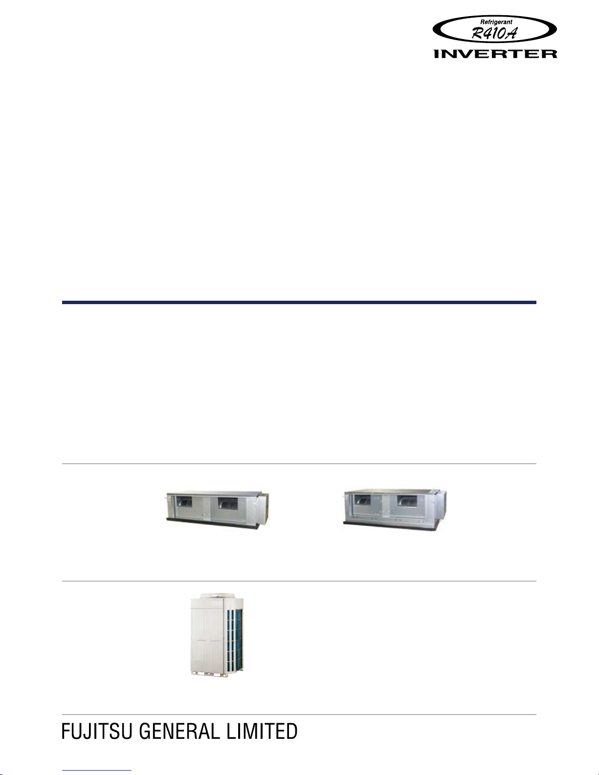
Easy service & maintenance
z
Outdoor unit
Indoor unit
Consolidated electrical
components make maintenance
easy
Maintenance of electrical
components, valves, and
compressor parts from
the front is possible.
Movable PCB panel that allows for
easier maintenance work behind
the PCB
Split front panel allows for
maintenance from top or
bottom of the outdoor unit
Easy-to-read 7-segment LED display
which explains operational and
trouble status
Fan unit
Left and Right fan motors can be removed
separately which has made servicing of
the indoor unit easier.
Page 8
- (01 - 05) -
DUCT TYPE
AR
C72-90LHTA
DUCT TYPE
AR
C72-90LHTA
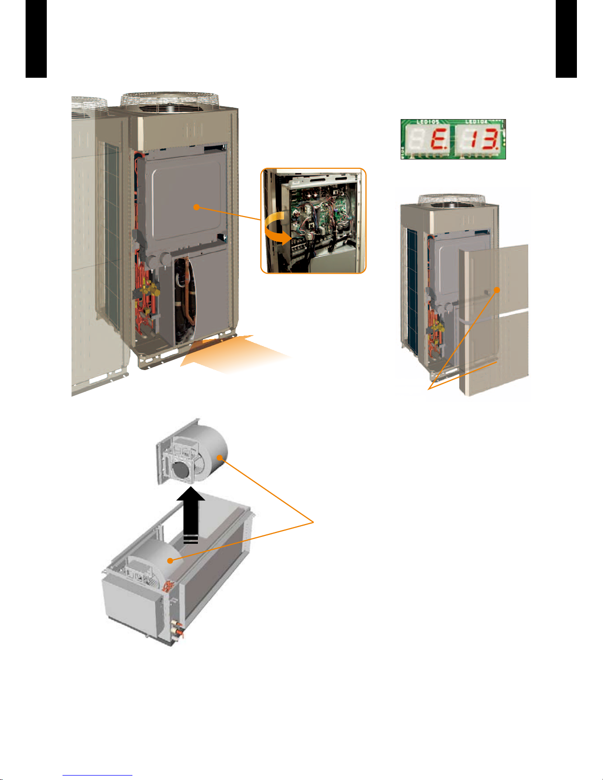
Adoption of blue n heat exchanger
z
Corrosion resistant of the heat exchanger has been improved by the introduction of blue n
treatment to the outdoor unit’s heat exchanger.
Improvement of piping length
z
Improvement of low outdoor ambient temperature performance
z
Blue fin heat exchanger
Standard chromate protec tion
Cobalt Blue protection
Aluminium base material
Hydrophilic coating
Previous model New model
50m 75m
Previous model New model
Cooling 0°C -5°C
Heating -10°C -15°C
Page 9
- (01 - 06) -
DUCT TYPE
AR
C72-90LHTA
DUCT TYPE
AR
C72-90LHTA
WIRED REMOTE CONTROLLER2.
FEATURES
Various timer setup (ON / OFF / WEEKLY) are possible.
Equipped with weekly timer as standard function.(2 times Start / Stop
per day for a week)
When setting up a timer, operation mode and a temperature setup
can be changed.
When a failure occurs, the error code is displayed. (Maximum of 16)
Error indication.(A maximum of 16 error histories are memorizable.)
Up to 16 indoor units can be simultaneously controlled.
The room temperature can be controlled by being detected the
temperature accurately with built-in thermo sensor.
Simple function setting
z
Setting of the air conditioner selection function is performed by remote controller.
High performance and compact size
z
Three functions are combined in
one unit.
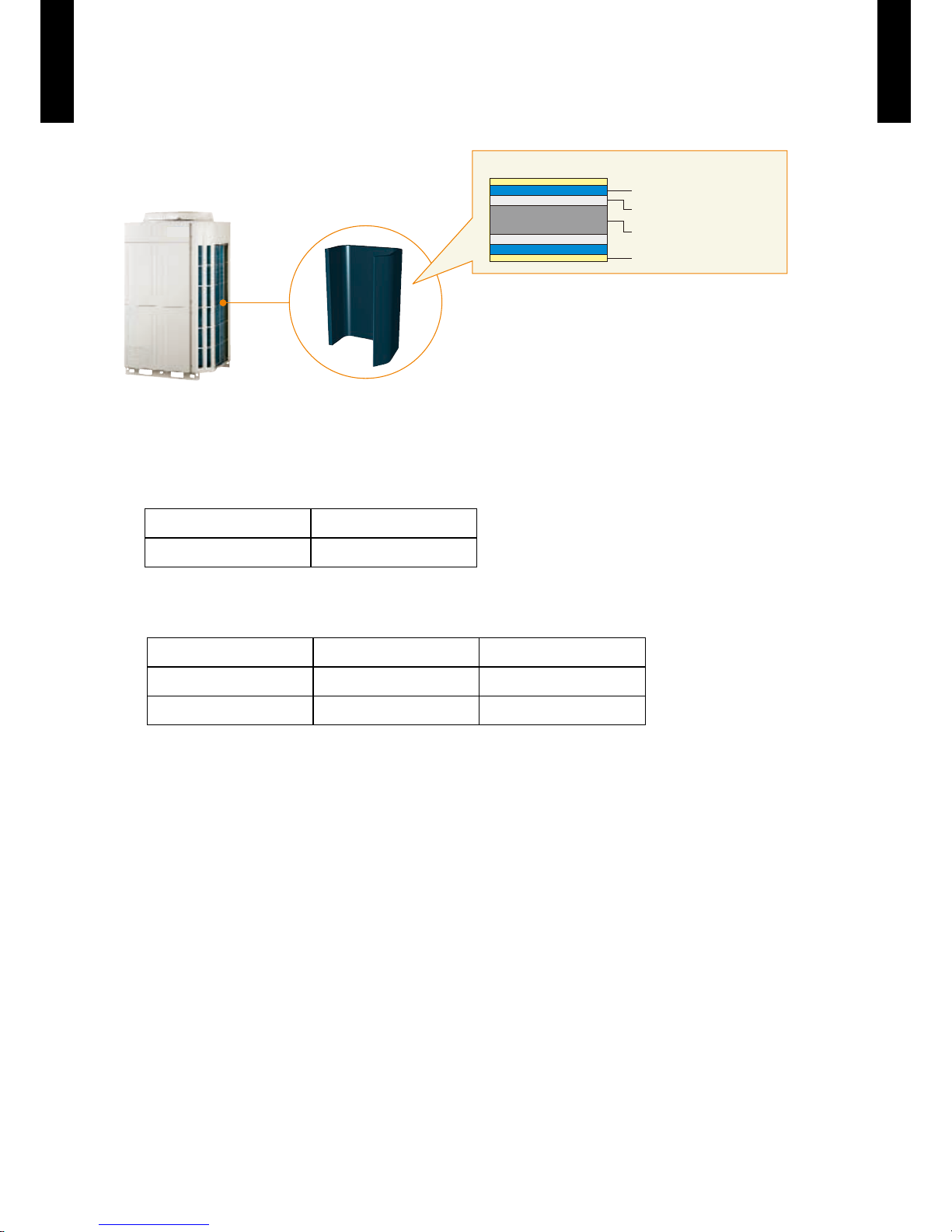
Built-in timers
z
Wired
remote
controller
Weekly
timer
Setback
timer
+ +
Weekly timer Setback timer
At "Weekly timer" + "Set back timer" setup
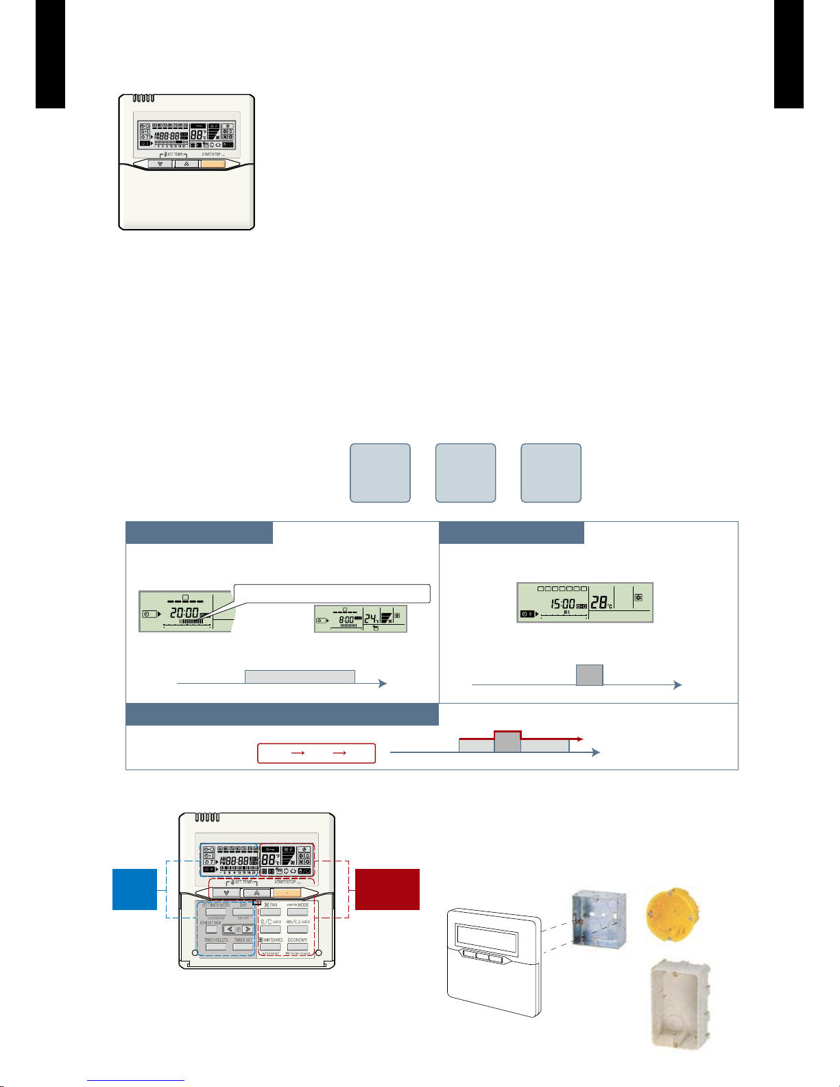
Easy-to-understand operation
z
[Variable timer control]
The operation/display sections are zoned
according to time and operation, enabling
variable programming to match application.
Simple installation
z
Components are compatible with standard
switch boxes. Flat back construction allows
equipment to be installed wherever it is
needed.
SUMOTUWETH FR SA
7
3126 9
15 18 21
SUMOTUWETH FR SA
7
3126 9
15 18 21
SUMOTUWETH FR SA
3126 9
15 18 21
Possible to set ON/OFF time to operate twice each day
of the week.
Setup scr een example
(Set to Wednes day: 8:00 to 20:00.)
Screen
after setup
European
switch box
JIS box
Setup scr een example
(Set from Sunday to Saturday: 12:00 to 15:0 0, 28 °C.)
Possible to set temperature for two time spans and
for each day of the week.
Easy-to-understand time bar display
24°C
0 3 6 9 12 15 18 21 Time
28°C
0 3 6 9 12 15 18 21 Time
28°C
24°C
0 3 6 9 12 15 18 21 Time
24°C 28°C 24°C
Timer
area
Operation
area
Page 10

- (01 - 07) -
DUCT TYPE
AR
C72-90LHTA
DUCT TYPE
AR
C72-90LHTA
FUNCTIONS
Display panel
DIMENSION
SPECIFICATION
WIRING SPECIFICATIONS
Use Size Wire type Remarks
Remote controller
cable
0.33mm
2
( 22AWG )
Polar 3 core Use sheathed PVC cable.
15
11
10
9
8
2
1
3
5
14
4
12
13
6
7
17
16
18
19
20
21
120
120
120
18
Side ViewFront View
SIZE (H x W x D mm) 120 x 120 x 18
WEIGHT ( g ) 160
CABLE LENGTH ( m ) 10
POWER ( V ) 12
1
START/STOP button
Pressed to start and stop operation.
2
SET TEMP. button
Selects the setting temperature.
3
MODE button
Selects the operating mode (AUTO, HEAT, FAN, COOL, DRY).
4
FAN button
Selects the fan speed (AUTO, LOW, MED, HIGH).
5
ECONOMY button
Turns the economy efcient mode on and off.
6
TIMER MODE (CLOCK ADJUST) button
Selects the timer mode (OFF TIMER, ON TIMER, WEEKLY
TIMER). Set the current time.
7
DAY (DAY OFF) button
Temporarily cancels of one day timer.
8
SET BACK button
Pressed to select the set back timer.
9
Set time button
Pressed to set time.
10
TIMER DELETE button
The schedule of a weekly timer is deleted.
11
TIMER SET button
Sets the date, hour, minute and on-off time.
12
Vertical airow direction and swing button
Push for two seconds to change the swing mode.
13
Horizontal airow direction and swing button
Push for two seconds to change the swing mode.
14
FILTER RESET button
15
Operation lamp
Lights during operation and when the timer is on.
16
Timer and clock display
17
Operation mode display
18
Fan speed display
19
Operation lock display
20
Temperature display
21
Function display
Defrost display
Thermo sensor display
Economy display
Vertical swing display
Horizontal swing display
Filter display
Functions will be different due to type of indoor unit.
For details, please see operation manual.
[ Unit : mm ]
Page 11

- (01 - 08) -
DUCT TYPE
AR
C72-90LHTA
DUCT TYPE
AR
C72-90LHTA
SPECIFICATIONS3.
Note :
Speci cations are base d on the foll owing conditio ns.
Coolin g : Indoor te mperat ure of 27 °CD B / 19 °CWB.an d outdoo r tempera ture of 35 °C DB/24 °C WB.
Heating : I ndoor te mperatu re of 20 °CD B / 15 °CWB.an d outdoor t emperat ure of 7 °CD B/6 °CWB .
Standa rd static p ressur e : 72Pa
Pipe leng th : 7.5 m, Height di ffere nce : 0 m.(Outd oor unit - I ndoor uni t)
The prote ctive fu nction m ay work whe n using it ou tside th e tempera ture rang e mentio ned above.
Drain ho se should b e eld sup plied.
* : The maxi mum curr ent is the ma ximum value when op erated wi thin the o perati on range.
Typ e Ducted m odel inver ter heatpump
Model na me ARC72L HTA ARC9 0LH TA
Power source 230V~ 50 Hz
Available voltage r ange 198-26 4V~ 50H z
Capacity
Cooling
Rated
kW 20.3 25.0
Btu/h 69300 85300
Min. - Max.
kW 10.8 - 23.5 11.2 - 28.0
Btu/h 3680 0 - 8020 0 3 8200 - 9 550 0
Heating
Rated
kW 22.6 28.0
Btu/h 77100 95500
Min. - Max.
kW 12.0 - 26.5 12.5 - 31.5
Btu/h 4090 0 - 904 00 42600 - 107500
Input power
Cooling
Rated
kW
6.25 7. 82
Max. 9.80 12 .10
Heating
Rated 6.27 8.24
Max. 9.80 12 .10
Current
Cooling Rated
A
9.6 11.9
Heating Rated 9.6 12.5
EER Cooling
kW/kW
3.25 3.20
COP Heating 3.60 3.40
Moisture removal l/h (pints/h) 4.5 (9.5) 6.0 (12.7)
Maximum operat ing cur rent *
Cooling
A
22.8 25.8
Heating 22.8 25.8
Fan
Air ow
rate
Cooling
High
m
3
/h
4300 4850
Med 3750 425 0
Low 315 0 3600
Heating
High 4300 4850
Med 3750 425 0
Low 315 0 3600
Fan type × Q'ty Sirocco × 2
Motor out put W 700 × 2
Static pressure range Pa 50-250 (Stand ard: 72)
Sound pressure level
Cooling
High
dB (A)
47 49
Med 44 46
Low 41 4 3
Heating
High 47 49
Med 44 46
Low 41 43
Heat exchanger type
Dimensions
mm
406.4 × 125 0 × 76.2 508 × 1250 × 76. 2
Fin pitch 1. 8 1.6
Rows x stag es 4 × 16 4 × 20
Pipe typ e Copper
Fin type Aluminium
Enclosure
Material Steel
Colour
-
Dimensions (H × W × D)
Net
mm
450 × 1587 × 700 550 × 1587 × 70 0
Gross 550 × 1750 × 825 650 × 1750 × 825
Weight
Net
kg
100 110
Gross 115 125
Connec tion pipe
Size
Liquid
mm
Ø12.7 (1/2 in.)
Gas Ø25.4 ( 1 in.)
Method Brazing
Operat ion rang e
Cooling
°C 18 to 32
%RH 80 or less
Heating °C 16 to 30
Remote co ntroller type Wired
Drain po rt
Material Steel
Size mm Ø3 5.7 (I.D.), Ø38.1 (O.D.)
Page 12

- (01 - 09) -
DUCT TYPE
AR
C72-90LHTA
DUCT TYPE
AR
C72-90LHTA
DIMENSIONS4.
MODEL : ARC72LHTA
(Unit : mm)
Page 13

- (01 - 10) -
DUCT TYPE
AR
C72-90LHTA
DUCT TYPE
AR
C72-90LHTA
MODEL : ARC90LHTA
(Unit : mm)
Page 14
- (01 - 11) -
DUCT TYPE
AR
C72-90LHTA
DUCT TYPE
AR
C72-90LHTA
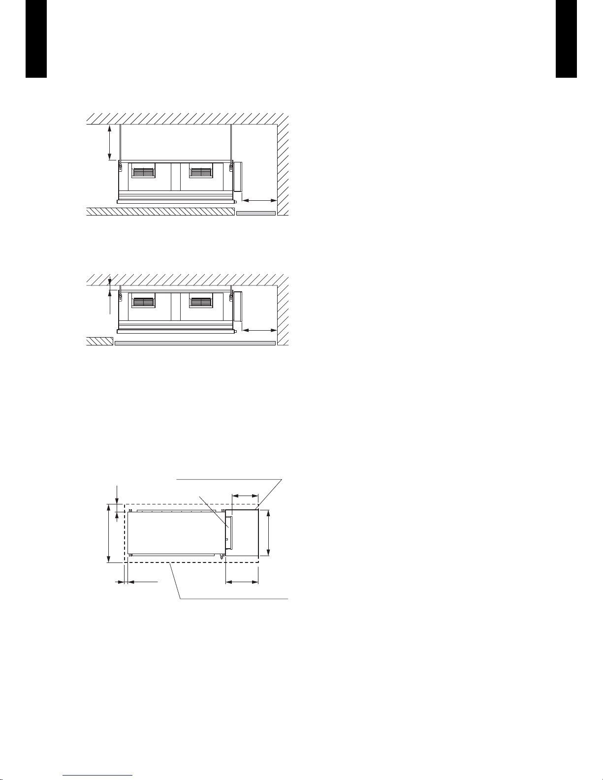
INSTALLATION PLACE
(Unit : mm)
(a) When service access will be carried out above the indoor unit a recommended installation
space of 450mm is required.
450
or
more
450
Service
space
eloh ecnanetniaM
(b) Installation by which service is carried out from the bottom of the unit
450
20 or
more
Service
space
Maintenance hole
MAINTENANCE HOLE
(Unit : mm)
(a) If maintenance work is to be done from the top, keep the space of the more than 450 mm
between the indoor unit and ceiling.
(b) If maintenance work is to be done from the bottom side, the maintenance hole needs to be
larger than the outside dimension of the indoor unit.
890
or
more
700
or
more
30 or
more
500 or
more
450 or more
200 or
more
Maintenannce hole size of (a)
Control box
Drain pan
Maintenannce hole size of (b)
Page 15
- (01 - 12) -
DUCT TYPE
AR
C72-90LHTA
DUCT TYPE
AR
C72-90LHTA
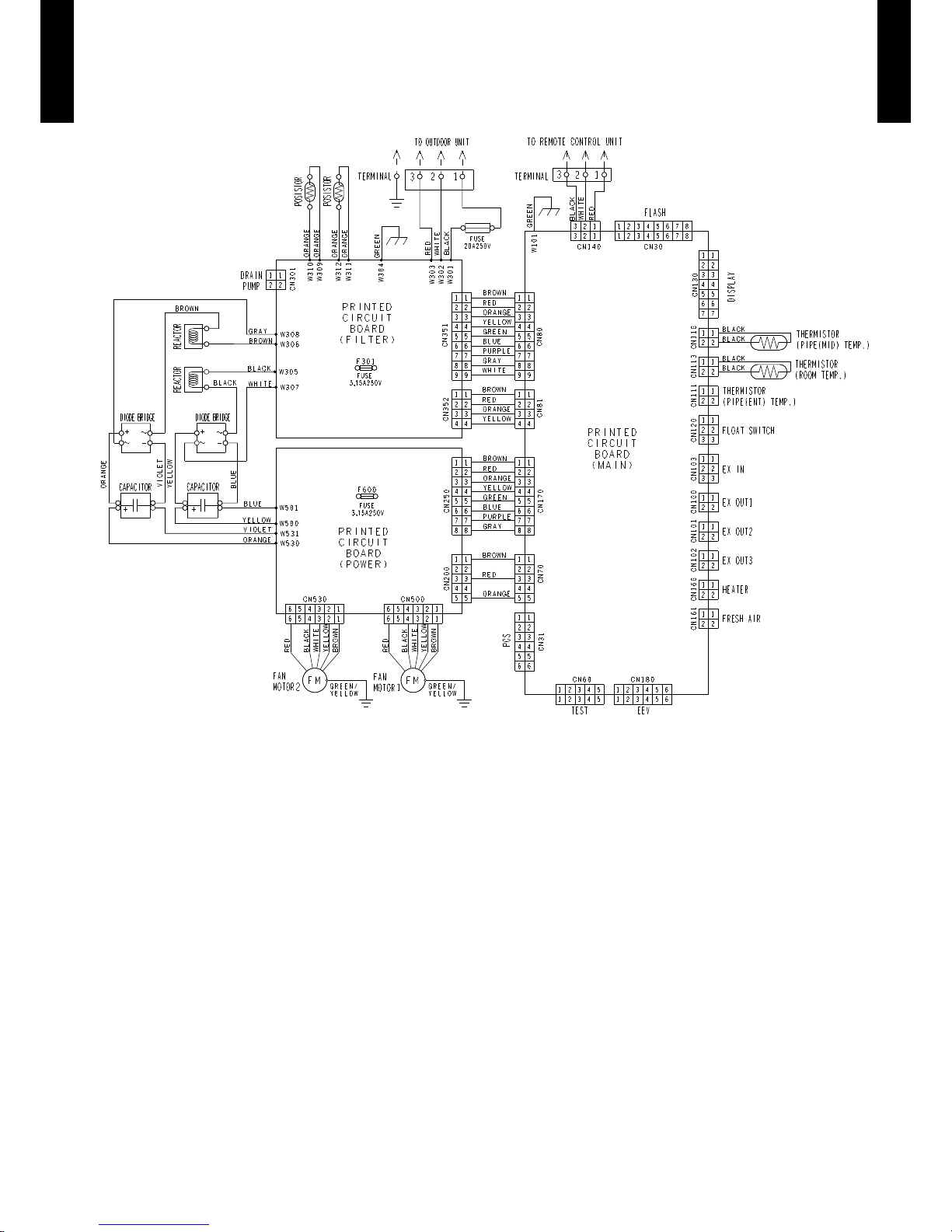
WIRING DIAGRAMS5.
MODEL : ARC72LHTA, ARC90LHTA
Page 16

- (01 - 13) -
DUCT TYPE
AR
C72-90LHTA
DUCT TYPE
AR
C72-90LHTA
CAPACITY TABLE6.
COOLING CAPACITY6-1.
MODEL : ARC72LHTA
MODEL : ARC90LHTA
AFR : Air o w rate (m3/min)
TC : Total capaci ty (kW)
SHC : Sensible Hea t capaci ty (kW)
IP : Input Powe r (kW)
AFR 71.7
Indoor temperature
°CDB 18 21 23 25 27 29 32
°CWB 12 15 16 18 19 21 23
Outdoor temperature
°CDB TC SHC IP TC SHC IP TC SHC IP TC SHC IP TC SHC IP TC SHC IP TC SHC IP
-5 17.64 15.08 3.23 19.65 15.17 3.28 20.32 16.49 3.29 21.66 16.54 3.33 22.33 17.87 3.34 23.67 17.80 3.38 25.01 18.96 3.41
0 17.61 15.05 3.28 19.61 15.14 3.33 20.28 16.46 3.34 21.62 16.51 3.38 22.29 17.83 3.40 23.63 17.76 3.43 24.96 18.92 3.46
5 17.57 15.02 3.38 19.58 15.11 3.43 20.24 16.43 3.45 21.58 16.48 3.48 22.25 17.80 3.50 23.58 17.72 3.54 24.91 18.88 3.57
10 17.39 15.05 3.69 19.37 15.14 3.75 20.03 16.46 3.77 21.35 16.51 3.80 22.01 17.83 3.82 23.33 17.76 3.86 24.65 18.92 3.90
15 17.28 14.87 4.07 19.25 14.96 4.13 19.91 16.26 4.16 21.22 16.31 4.20 21.88 17.62 4.22 23.19 17.55 4.26 24.50 18.69 4.30
20 17.27 14.85 4.69 19.24 14.93 4.76 19.90 16.24 4.78 21.21 16.29 4.83 21.86 17.59 4.86 23.17 17.52 4.91 24.49 18.66 4.95
25 17.27 14.31 5.39 19.23 14.40 5.48 19.89 15.65 5.51 21.20 15.70 5.56 21.86 16.96 5.59 23.17 16.89 5.65 24.48 17.99 5.70
30 16.90 14.19 5.90 18.82 14.28 5.99 19.46 15.52 6.02 20.75 15.57 6.08 21.39 16.82 6.11 22.67 16.75 6.17 23.96 17.84 6.24
35 16.04 14.67 6.03 17.86 14.76 6.13 18.47 16.04 6.16 19.69 16.09 6.22 20.30 17.38 6.25 21.52 17.31 6.31 22.74 18.44 6.38
40 15.97 13.83 7.67 17.79 13.92 7.79 18.40 15.13 7.83 19.61 15.18 7.91 20.22 16.39 7.95 21.43 16.33 8.03 22.65 17.39 8.10
46 15.16 14.14 8.51 16.89 14.23 8.64 17.46 15.47 8.69 18.62 15.52 8.77 19.19 16.76 8.82 20.34 16.69 8.91 21.50 17.78 8.99
AFR 80.8
Indoor temperature
°CDB 18 21 23 25 27 29 32
°CWB 12 15 16 18 19 21 23
Outdoor temperature
°CDB TC SHC IP TC SHC IP TC SHC IP TC SHC IP TC SHC IP TC SHC IP TC SHC IP
-5 21.66 18.51 4.85 24.13 18.62 4.92 24.95 20.24 4.95 26.59 20.31 5.00 27.42 21.93 5.02 29.06 21.85 5.07 30.71 23.27 5.12
0 21.65 18.50 4.94 24.12 18.61 5.02 24.94 20.24 5.04 26.58 20.30 5.09 27.41 21.92 5.12 29.05 21.84 5.17 30.69 23.26 5.22
5 21.54 18.41 5.16 23.99 18.52 5.24 24.81 20.13 5.27 26.44 20.20 5.32 27.26 21.81 5.35 28.90 21.72 5.40 30.53 23.14 5.46
10 21.53 18.63 5.80 23.98 18.74 5.89 24.80 20.37 5.92 26.43 20.44 5.98 27.25 22.07 6.01 28.89 21.99 6.07 30.52 23.42 6.13
15 21.39 18.51 6.14 23.83 18.62 6.23 24.64 20.25 6.27 26.27 20.31 6.33 27.08 21.94 6.36 28.71 21.85 6.42 30.33 23.28 6.49
20 21.37 18.49 6.67 23.80 18.60 6.77 24.61 20.22 6.81 26.23 20.29 6.87 27.05 21.91 6.91 28.67 21.82 6.98 30.29 23.24 7.05
25 21.31 17.91 7.20 23.74 18.01 7.32 24.54 19.58 7.35 26.16 19.65 7.43 26.97 21.22 7.47 28.59 21.13 7.54 30.21 22.51 7.61
30 21.12 18.09 7.52 23.53 18.20 7.64 24.33 19.78 7.68 25.93 19.85 7.75 26.74 21.44 7.79 28.34 21.35 7.87 29.94 22.74 7.95
35 19.75 17.81 7.55 22.00 17.91 7.66 22.75 19.48 7.70 24.25 19.54 7.78 25.00 21.10 7.82 26.50 21.02 7.90 28.00 22.39 7.98
40 19.55 16.99 9.65 21.78 17.09 9.80 22.52 18.58 9.85 24.00 18.64 9.95 24.75 20.13 10.00 26.23 20.05 10.10 27.72 21.36 10.20
46 17.77 16.49 10.27 19.79 16.59 10.43 20.46 18.03 10.48 21.81 18.09 10.59 22.49 19.54 10.64 23.84 19.46 10.75 25.19 20.73 10.85
Page 17

- (01 - 14) -
DUCT TYPE
AR
C72-90LHTA
DUCT TYPE
AR
C72-90LHTA
HEATING CAPACITY6-2.
MODEL : ARC72LHTA
MODEL : ARC90LHTA
AFR : Air o w rate (m3/min)
TC : Total c apacity (kW)
IP : Input Power (k W)
AFR 71.7
Indoor temperature
°CDB 16 18 20 22 24
Outdoor temperature
°CDB °CWB TC IP TC IP TC IP TC IP TC IP
-15 -16 17.79 7.07 17.37 7.22 16.95 7.37 16.52 7.52 16.10 7.66
-10 -11 20.37 7.45 19.89 7.60 19.40 7.76 18.92 7.91 18.43 8.07
-5 -7 22.32 7.68 21.79 7.84 21.26 8.00 20.73 8.16 20.20 8.32
0 -2 23.33 7.71 22.77 7.87 22.22 8.03 21.66 8.19 21.11 8.35
5 3 23.73 6.70 23.17 6.84 22.60 6.98 22.04 7.12 21.47 7.26
7 6 23.73 6.02 23.17 6.14 22.60 6.27 22.04 6.40 21.47 6.52
10 8 27.79 6.97 27.13 7.12 26.47 7.26 25.80 7.41 25.14 7.55
15 10 28.05 6.78 27.38 6.92 26.71 7.06 26.05 7.20 25.38 7.31
20 15 29.08 6.81 28.38 6.95 27.69 7.09 27.00 7.23 26.31 7.34
24 18 29.23 6.66 28.53 6.80 27.84 6.94 27.14 7.07 26.44 7.18
AFR 80.8
Indoor temperature
°CDB 16 18 20 22 24
Outdoor temperature
°CDB °CWB TC IP TC IP TC IP TC IP TC IP
-15 -16 20.51 8.48 20.02 8.66 19.53 8.84 19.04 9.01 18.55 9.19
-10 -11 23.90 9.02 23.33 9.20 22.76 9.39 22.19 9.58 21.62 9.77
-5 -7 26.54 9.40 25.90 9.60 25.27 9.79 24.64 9.99 24.01 10.19
0 -2 28.04 9.57 27.37 9.77 26.70 9.97 26.03 10.17 25.37 10.37
5 3 29.09 8.60 28.40 8.78 27.71 8.96 27.02 9.14 26.32 9.32
7 6 29.40 7.91 28.70 8.08 28.00 8.24 27.30 8.40 26.60 8.57
10 8 34.65 9.18 33.82 9.37 33.00 9.56 32.17 9.75 31.35 9.94
15 10 35.98 9.16 35.12 9.36 34.26 9.55 33.41 9.74 32.55 9.88
20 15 36.36 8.98 35.50 9.17 34.63 9.36 33.77 9.54 32.90 9.68
24 18 36.76 8.84 35.89 9.03 35.01 9.21 34.14 9.40 33.26 9.54
Page 18
- (01 - 15) -
DUCT TYPE
AR
C72-90LHTA
DUCT TYPE
AR
C72-90LHTA
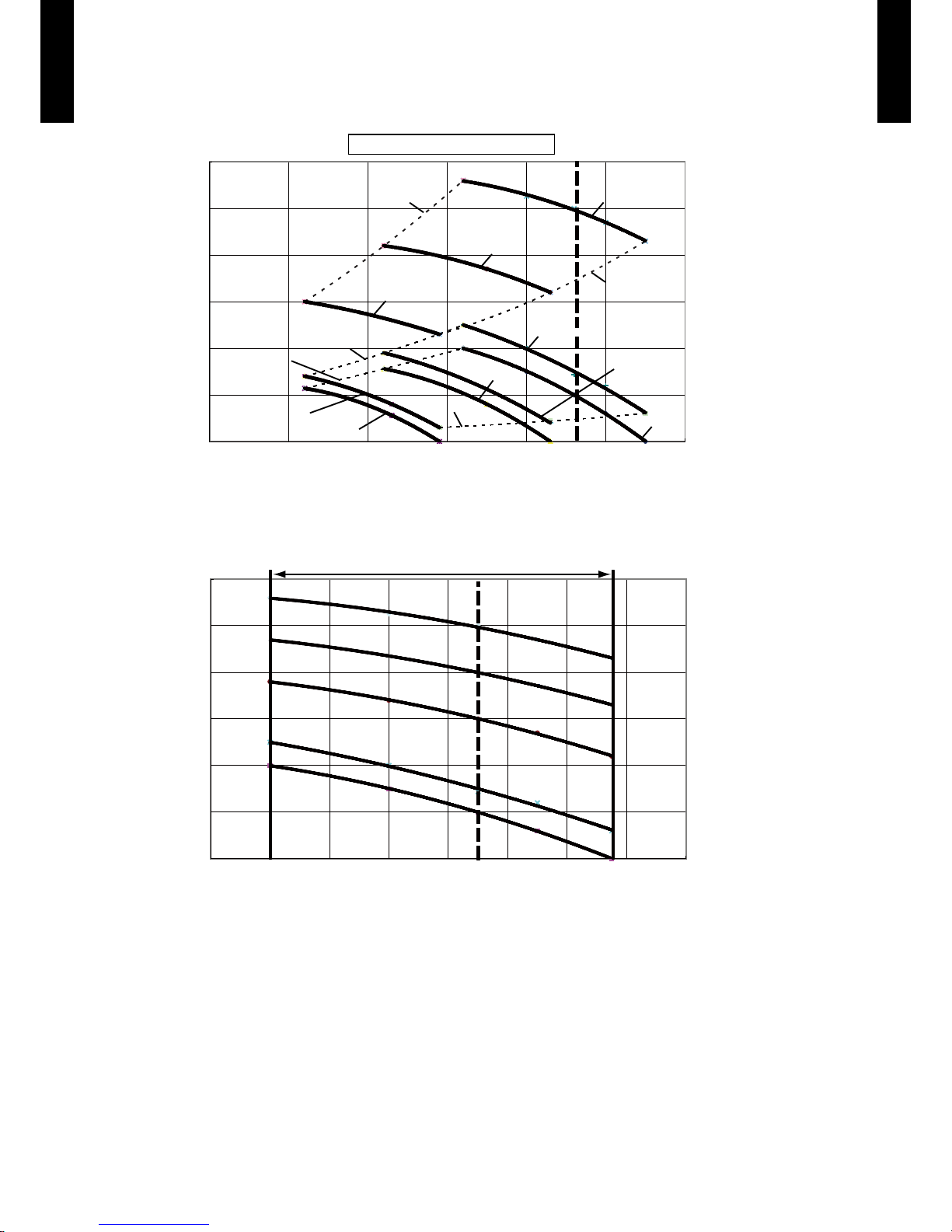
FAN PERFORMANCE AND CAPACITY7.
MODEL : ARC72LHTA
Q-h Characteristic curve
Hi(HSP mode3)
HSP mode3
Lower limit
Med(HSP mode3)
Hi(Normal SP mode)
Med(Normal SP mode)
Hi(LSP mode)
Med(LSP mode)
Normal SP
mode Lower limit
Lo(LSP mode)
Lo(Normal SP mode)
LSP mode
Upper limit
Normal SP mode
Upper limit
Lo(HSP mode3)
HSP mode3
Upper limit
300
250
200
150
100
50
0
Static pressure(Pa)
Airow
2,000 2,500 3,000 3,500 4,000 4,50 0 5,000 (m3/h)
300
250
200
150
100
50
0
Static pressure(Pa)
Airow
3,400 3,600 3,800 4,000 4,200 4,400 4,600 4,800 5,00 0 (m3/h)
Hi HSP mode3
(250Pa)
Hi HSP mode2
(200Pa)
Hi HSP mode1
(150Pa)
Hi Normal SP mode
(72Pa)
Hi LSP mode
(50Pa)
Available air flow rate range (High level)
Page 19

- (01 - 16) -
DUCT TYPE
AR
C72-90LHTA
DUCT TYPE
AR
C72-90LHTA
MODEL : ARC72LHTA
Cooling
z
Heating
z
92
94
96
98
100
102
3,400 3,600 3,800 4,000 4,200 4,400 4,600 4,800 5,000
capacit
䡕
(%)
Airflow
(m
3
/h)
Capacity
92
94
96
98
100
102
3,400 3,600 3,800 4,000 4,200 4,400 4,600 4,800 5,000 (m
3
/h)
Airflow
capacity(%)
Capacity
Page 20

- (01 - 17) -
DUCT TYPE
AR
C72-90LHTA
DUCT TYPE
AR
C72-90LHTA
MODEL : ARC90LHTA
300
250
200
150
100
50
0
Static pressure(Pa)
Airow
Q-h Characteristic curve
300
250
200
150
100
50
0
Static pressure(Pa)
Airow
2,500 3,00 0 3,500 4,000 4,500 5,00 0 5,500 (m3/h)
Hi(HSP mode3)
HSP mode3
Lower limit
Med(HSP mode3)
Hi(Normal SP mode)
Med(Normal SP mode)
Hi(LSP mode)
Med(LSP mode)
Normal SP
mode Lower limit
Lo(LSP mode)
Lo(Normal SP mode)
LSP mode
Upper limit
Normal SP mode
Upper limit
Lo(HSP mode3)
HSP mode3
Upper limit
Hi HSP mode3
(250Pa)
Hi HSP mode2
(200Pa)
Hi HSP mode1
(150Pa)
Hi Normal SP mode
(72Pa)
Hi LSP mode
(50Pa)
Available air flow rate range (High level)
3,700 3,900 4,100 4, 300 4,500 4,700 4,900 5,100 5, 300 5,500 (m3/h)
Page 21

- (01 - 18) -
DUCT TYPE
AR
C72-90LHTA
DUCT TYPE
AR
C72-90LHTA
MODEL : ARC90LHTA
Cooling
z
Heating
z
92
94
96
98
100
102
3,700 3,900 4,100 4,300 4,500 4,700 4,900 5,100 5,300 5,500
capacity(%)
Airflow
(m
3
/h)
Capacity
92
94
96
98
100
102
capacit
䡕
(%)
3,700 3,900 4,100 4,300 4,500 4,700 4,900 5,100 5,300 5,500
Airflow
(m
3
/h)
Capacity
Page 22

- (01 - 19) -
DUCT TYPE
AR
C72-90LHTA
DUCT TYPE
AR
C72-90LHTA
OPERATION NOISE8.
NOISE LEVEL CURVE8-1.
MODEL : ARC72LHTA
Condition
Static pressure : 72Pa
Static pressure mode : Normal
HIGH
LOW
Heating
z
Octave ba nd sound p ressur e level, dB:(0 dB= 0.00 02µbar)
80
70
60
50
40
30
20
10
0
NC-65
NC-60
NC-55
NC-50
NC-45
NC-40
NC-35
NC-30
NC-25
NC-20
NC -15
HIGH
LOW
Cooling
z
Octave ba nd sound p ressur e level, dB:(0 dB= 0.00 02µbar)
Octave ba nd cente r frequency,Hz
80
70
60
50
40
30
20
10
0
NC-65
NC-60
NC-55
NC-50
NC-45
NC-40
NC-35
NC-30
NC-25
NC-20
NC -15
HIGH
LOW
Octave ba nd sound p ressur e level, dB:(0 dB= 0.00 02µbar)
80
70
60
50
40
30
20
10
0
NC-65
NC-60
NC-55
NC-50
NC-45
NC-40
NC-35
NC-30
NC-25
NC-20
NC -15
HIGH
LOW
Heating
z
Octave ba nd sound p ressur e level, dB:(0 dB= 0.00 02µbar)
80
70
60
50
40
30
20
10
0
NC-65
NC-60
NC-55
NC-50
NC-45
NC-40
NC-35
NC-30
NC-25
NC-20
NC -15
MODEL : ARC90LHTA
Cooling
z
Octave ba nd cente r frequency,Hz
63 125 250 50 0 1,000 2 ,000 4 ,000 8,000
Octave ba nd cente r frequency,Hz
63 125 250 50 0 1,000 2 ,000 4 ,000 8,000
Octave ba nd cente r frequency,Hz
63 125 250 50 0 1,000 2 ,000 4 ,000 8,000
63 125 250 50 0 1,000 2 ,000 4 ,000 8,000
Page 23

- (01 - 20) -
DUCT TYPE
AR
C72-90LHTA
DUCT TYPE
AR
C72-90LHTA
SOUND LEVEL CHECK POINT8-2.
Microphone
Measuring duct
Measuring duct
Set the static pressure
as rating in this area
2 m 1 m
1.5 m
Microphone
AIR
Page 24

- (01 - 21) -
DUCT TYPE
AR
C72-90LHTA
DUCT TYPE
AR
C72-90LHTA
ELECTRIC CHARACTERISTICS9.
Model name
ARC72LHTA
ARC9 0LHTA
Power supply
Voltage V 230 ~
Frequency Hz 50
Max. operating current (Indoor unit) A 9.3
Wiring spec.
(Indoor unit to outdoor unit)
Connection cable mm
2
1.5 2.5
Limited wiring length m 50 or less 50 to 76
Note: Wiring specication
1. Selected sample
(Selected based on Japan Electrotechnical Standard and Codes Committee E0005)
2. Limited wiring length : Limit voltage drop to less than 2%. Increase cable gauge if voltage drop is 2% or more.
3. If the transmission wire is longer than 50m, use the bigger conductor size.
Page 25

- (01 - 22) -
DUCT TYPE
AR
C72-90LHTA
DUCT TYPE
AR
C72-90LHTA
SAFETY DEVICES10.
Protection form
Model
ARC72LHTA
ARC9 0LHTA
Circuit protection Current fuse (PCB) 250V 3.15A
Fan motor protection Thermal protection program
100°C
+15°C
OFF
-10°C
95°C
+15°C
ON
-10°C
Page 26

- (01 - 23) -
DUCT TYPE
AR
C72-90LHTA
DUCT TYPE
AR
C72-90LHTA
EXTERNAL INPUT & OUTPUT11.
EXTERNAL INPUT11-1.
CONTROL INPUT (Operation/Stop)
The air conditioner can be remotely operated by means of the following on-site work.
Operation is started at the following contents by adding the contact input of a commercial ON/OFF
switch to a connector on the external control PC board and turning it ON.
Unit operation Initial setting after power is ON Starting mode other than initial setting
Operation mode Auto changeover Mode at previous operation
Set temperature 24°C Temperature at previous operation
Air ow mode AUTO Mode at previous operation
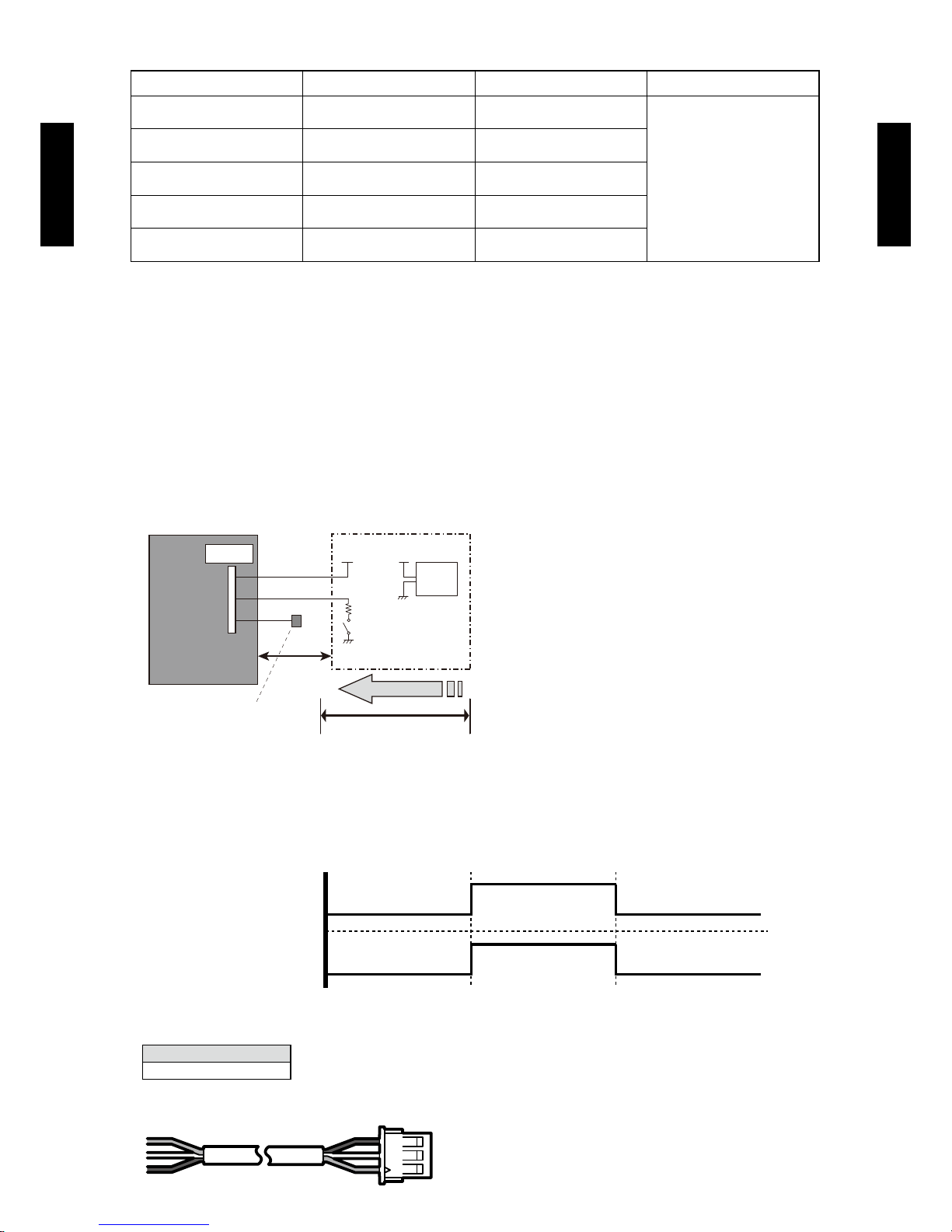
Circuit diagram example
z
Indoor
control PC board
Connector
1
2
3
Signal
Field supply
* Make the distance from the PC board to the connected unit within 10 m.
Contact capacity : 5VDC or more, 15mA or more.
Please use non-polar relays and switches.
Surely insulate with
insulation tape etc. since
this wire is not used.
*10 m
Connected unit
Ex.) Switch
Operation
Stop
ON
OFF
Input signal
Indoor unit
Parts (Optional)
z
Model name
UTD-ECS5A
Wire (External input)
INPUT OUTPUT Connector REMARKS
CONTROL INPUT
(OPERATION/STOP)
— CN103
See external
input/output settings
for details.
— OPERATION STATUS CN100
— ERROR STATUS CN101
— FRESH AIR CONTROL CN161
—
AUXILIARY HEATER
CN160
Page 27

- (01 - 24) -
DUCT TYPE
AR
C72-90LHTA
DUCT TYPE
AR
C72-90LHTA
EXTERNAL OUTPUT11-2.
OPERATION STATUS OUTPUT
An air conditioner operation status signal can be output.
Circuit diagram example
z
Field supply
Ex.)Display
Indoor
control PC board
Connected unit
Ex.)Relay unit
1
2
Signal
Relay
power
supply
V
Connector
* Make the distance from the PC board to the connected unit within 10m.
Relay spec. : Max.24VDC, 10mA to less than 500mA.
*10 m
24V DC
ON
OFF
Operation
Stop
Indoor unit
Output signal
Parts (Optional)
z
Model name
UTD-ECS5A
Wire (External output)
Page 28

- (01 - 25) -
DUCT TYPE
AR
C72-90LHTA
DUCT TYPE
AR
C72-90LHTA
ERROR STATUS OUTPUT
An air conditioner condition normal/error status signal can be output.
Circuit diagram example
z
Field supply
Ex.)Display
Indoor
control PC board
Connected unit
Ex.)Relay unit
1
2
Signal
Relay
power
supply
V
Connector
* Make the distance from the PC board to the connected unit within 10m.
Relay spec. : Max.24VDC, 10mA to less than 500mA.
*10 m
24V DC
ON
OFF
Error
Normal
Error status
Output signal
Parts (Optional)
z
Model name
UTD-ECS5A
Wire (External output)
Page 29

- (01 - 26) -
DUCT TYPE
AR
C72-90LHTA
DUCT TYPE
AR
C72-90LHTA
FRESH AIR CONTROL OUTPUT
A signal linked to air conditioner indoor fan ON can be output.
* However, signal becomes OFF during cold air prevention control operation.
Circuit diagram example
z
Field supply
Indoor
control PC board
Connector
1
12 V
on/off
2
Signal
Relay
power
supply
* Make the distance from the PC board to the connected unit within 10m.
Relay spec. : Rated 12VDC, 50mA or less.
Ex.) Fan
Connected unit
Ex.) Relay unit
*10 m
ON
OFF
Operation
Stop
Indoor fan
Output signal
Parts (Optional)
z
Model name
UTD-ECS5A
Wire (Fresh air output)
Page 30

- (01 - 27) -
DUCT TYPE
AR
C72-90LHTA
DUCT TYPE
AR
C72-90LHTA
AUXILIARY HEATER OUTPUT
A signal is outputed from Connector when indoor fan and compressor is turned on under heating
operation.
* Signal output performance specications are as
shown on the right
Ex. When Set Temperature(Ts) is 22°C;
▪ and Room Temperature(Tr) increase above 12°C,
signal output is on.
▪ and Room Temperature(Tr) increase above 21°C,
signal output is off.
▪ and Room Temperature(Tr) decrease below 19°C, signal output is on.
▪and Room Temperature(Tr) decrease below 10°C, signal output is off.
Jumper wire (Indoor Unit)
z
This is used to continue indoor unit fan operation for 1 minute after thermo OFF in heating mode.
1 minute delay control set by cutting jumper wire on PCB.
Circuit diagram example
z
Field supply
Indoor unit
control PC board
Connector
1
12 V
on/off
2
Signal
Relay
power
supply
* Make the distance from the PC board to the connected unit within 10m.
Relay spec. : Rated 12VDC, 50mA or less.
Ex.) Heater
Connected unit
Ex.) Relay unit
*10 m
ON
OFF
Operation
Stop
Heating
operation
Indoor unit fan
ON
OFF
Output signal
1min
OFF
OFF
ON
Tr-Ts = -1°C
Tr-Ts
Tr-Ts = -3°C
Tr-Ts = -10°C
Tr-Ts = -12°C
Page 31

- (01 - 28) -
DUCT TYPE
AR
C72-90LHTA
DUCT TYPE
AR
C72-90LHTA
!
CAUTION
Please place an external a heater between the indoor unit and the ductwork.
Please be sure to use delay control of the fan.
Parts (Optional)
z
Model name
UTD-ECS5A
Wire (Heater output)
Exter nal
Heater
Supply air Return air
Indooruni t
Page 32

- (01 - 29) -
DUCT TYPE
AR
C72-90LHTA
DUCT TYPE
AR
C72-90LHTA
FUNCTION SETTINGS12.
INDOOR UNIT12-1.
SWITCH POSITION
DIP-SW SETTING
Remote controller address setting (SW50)
z
A number of indoor units can be operated at the same time using a single remote controller.
Set the unit number of each indoor unit using the DIP switches on the indoor unit circuit board.
(See the following table.)
The DIP switches are normally set to make the unit number 00.
(. . .Factory setting)
Remote controller address
DIP switch No.
1 2 3 4
00 OFF OFF OFF OFF
01 ON OFF OFF OFF
02 OFF ON OFF OFF
03 ON ON OFF OFF
04 OFF OFF ON OFF
05 ON OFF ON OFF
06 OFF ON ON OFF
07 ON ON ON OFF
08 OFF OFF OFF ON
09 ON OFF OFF ON
10 OFF ON OFF ON
11 ON ON OFF ON
12 OFF OFF ON ON
13 ON OFF ON ON
14 OFF ON ON ON
15 ON ON ON ON
INDOOR UNIT
DIP-SW50
1
Remote controller address setting
2
3
4
Jumper Wire
JM40
Setting forbidden
JM41
JM42 Fan delay setting
JM40
JM41
JM42
SW50
1 2 3 4
ON
OFF
MAIN PCB
Page 33

- (01 - 30) -
DUCT TYPE
AR
C72-90LHTA
DUCT TYPE
AR
C72-90LHTA
JUMPER WIRE SETTING
Fan delay setting (JM42)
z
When the indoor unit is stopped while operating in conjunction with auxiliary heater, the indoor unit
fan operation will continue for one minute..
(
Factory setting)
JM 42 JM state
Connect Invalidity
Disconnect Validity
Page 34

- (01 - 31) -
DUCT TYPE
AR
C72-90LHTA
DUCT TYPE
AR
C72-90LHTA
INDOOR UNIT (Setting by remote controller)12-2.
The function settings of the control of the indoor unit can be changed by this procedure according •
to the installation conditions. Incorrect settings can cause the indoor unit to malfunction.
After the power is turned on, perform The Function Setting according to the installation conditions •
using the remote controller.
The settings may be selected between the following two: Function Number or Setting Value. •
Settings will not be changed if invalid numbers or setting values are selected. •
PREPARATION
Turn on the power. •
* Before turning on the power of the indoor units, make sure the piping air-tight test and vacuuming
have been conducted.
* Also check again to make sure no wiring mistakes were made before turning on the power.
FUNCTION SETTING METHOD (for Wired remote controller)
Setting method
z
(1) Press the SET TEMP. buttons ( ) ( ) and FAN button simultaneously for more than 5 seconds to enter the function setting mode.
SU
MO
TU
WE
TH FR
SA
(2) Press the SET BACK button to select the indoor unit number.
SET BACK
SUMOTUWETH FR
SA
Unit number of INDOOR UNIT
3) Press the Set time buttons to select the function number.
Function number
SUMOTUWETH FR
SA
(4) Press the SET TEMP. buttons ( ) ( ) to select the setting value. The display ashes during setting value selection.
Settin g value
SUMOTUWETH FR
SA
Page 35

- (01 - 32) -
DUCT TYPE
AR
C72-90LHTA
DUCT TYPE
AR
C72-90LHTA
(5) Press the TIMER SET button to conrm the setting. Press the TIMER SET button for a few seconds until the setting value stops
ashing. If the setting value display changes or if “- -” is displayed when the ashing stops, the setting value has not been set correctly.
(An invalid setting value may have been selected for the indoor unit.)
(6) Repeat steps 2 to 5 to perform additional settings. Press the SET TEMP. buttons (
) ( ) and FAN button simultaneously again for
more than 5 seconds to cancel the function setting mode. In addition, the function setting mode will be automatically canceled after 1
minute if no operation is performed.
(7) After completing the FUNCTION SETTING, be sure to turn of f the power and turn it on again.
!
CAUTION
• After turning off the power, wait 30 seconds or more before turning on it again. The Function Setting will not become active
unless the power is turned off then on again.
CONTENTS OF FUNCTION SETTING
• Follow the instructions in the Local Setup Procedure, which is supplied with the remote control, in accordance with the installed
condition.
After the power is turned on, per form the Function Setting on the remote control.
• The settings may be selected between the following t wo: Function Number or Setting Value.
• Settings will not be changed if invalid numbers or setting values are selected.
1) Static pressure
2) Room temperature control for cooling
3) Room temperature control for heating
4) Auto restart
5) Room temperature sensor switching
6) Cool air prevention
7) Room temperature sensor switching (Aux
.)
1) Static pressure
Select the appropriate static pressure according to the installation conditions.
(. . .Factory setting)
Setting Description
Function
Number
Setting Value
Normal (72Pa)
21
00
Low static pressure (50Pa) 02
High static pressure 1 (150Pa) 03
High static pressure 2 (200Pa) 04
High static pressure 3 (250Pa) 05
2) Room temperature control for cooling
Depending on the installed environment, correction of the room temperature sensor may be required.
Select the appropriate control setting according to the installed environment.
(. . .Factory setting)
Setting Description
Function
Number
Setting Value
Standard
30
00
Higher control 01
Slightly higher control 02
Slightly lower control 03
Lower control 04
Page 36

- (01 - 33) -
DUCT TYPE
AR
C72-90LHTA
DUCT TYPE
AR
C72-90LHTA
3) Room temperature control for heating
Depending on the installed environment, correction of the room temperature sensor may be required.
Select the appropriate control setting according to the installed environment..
(. . .Factory setting)
Setting Description
Function
Numbe
Setting Value
Standard
31
00
Higher control 01
Slightly higher control 02
Slightly lower control 03
Lower control 04
4) Auto restart
Enable or disable automatic system restart after a power outage.
(. . .Factory setting)
Setting Description
Function
Number
Setting Value
Enable
40
00
Disable 01
* Auto restar t is an emergency function such as for power failure etc. Do not start and stop the indoor unit by this function in
normal operation. Be sure to operate by the control unit, or external input device.
5) Room temperature sensor switching
(Only for wired remote controller)
When using the Wired remote controller temperature sensor, change the setting to "Both" (01).
(. . .Factory setting)
Setting Description
Function
Number
Setting Value
Indoor unit
42
00
Both 01
*00: Sensor on the indoor unit is active.
01: Sensors on both indoor unit and wired remote controller are active.
*Remote controller sensor must be turned on by using the remote controller.
6) Cool air prevention
This setting is to disable the cold air prevention function during heating operation. When disabled, the fan setting will always follow the
setting on the remote controller. (Excluding defrost mode)
(. . .Factory setting)
Setting Description
Function
Number
Setting Value
Enable
43
00
Disable 01
7) Room temperature sensor switching (Aux.)
o use the temperature sensor on the wired remote controller only, change the setting to "Wired remote controller" (01). This function will
only work if the function setting 42 is set at "Both" (01)
(. . .Factory setting)
Setting Description
Function
Number
Setting Value
Both
48
00
Wired remote controller 01
Page 37

- (01 - 34) -
DUCT TYPE
AR
C72-90LHTA
DUCT TYPE
AR
C72-90LHTA
WIRED REMOTE CONTROLLER12-3.
SWITCH POSITION
DIP SWITCH SETTING
Dual remote controller setting
z
Set the remote controller DIP switch No.2 according to the following table.
Memory backup setting
z
Set to ON to use batteries for the memory backup. If batteries are not used, all of the settings
stored in memory will be deleted if there is a power failure.
DIP SW
1 Can not be used. (Do not change)
2 Dual remote controller setting
3 Can not be used. (Do not change)
4 Can not be used. (Do not change)
5 Can not be used. (Do not change)
6 Memory backup setting
ON
ON
OFF
1
2
3
4
5
6
Front case (back side)
Do not use this
DIP Switch
DIP Switch
(
Factory setting)
Number
of remote
controller
Primary unit Secondary unit
DIP-SW No.2 DIP-SW No.2
1 (Normal) OFF ―
2 (Dual) OFF ON
(
Factory setting)
DIP-SW
No.6
Memory backup
OFF Invalidity
ON Validity
Page 38

- (01 - 35) -
DUCT TYPE
AR
C72-90LHTA
DUCT TYPE
AR
C72-90LHTA
OPTIONAL PARTS13.
CONTROLLER13-1.
Exterior Parts name Model No. Summary
Wired
remote
controller
UTY-
RVNM
Large and full-dot liquid crystal
screen, wide and large keys
easy to press, user-intuitive
arrow key.
Wired
remote
controller
UTY-
RNNM
The room temperature can be
controlled by being detected
the temperature accurately
with built-in thermo sensor.
Simple
remote
controller
UTY-
RSNM
Compact remote controller
concentrates on the basic
functions such as Start/Stop, Fan
Control, Temperature Setting and
Operation mode.
OTHERS13-2.
Exterior Parts name Model No. Summary
Remote
sensor
UTY-XSZ X
New amenity space can be
offered by installing the Remote
sensor in the remote controller.
( x 1 ) ( x 2 )
( x 1 ) ( x 2 )
External
control set
UTD-ECS5A
Use to connect with various
peripheral devices and air
conditioner PC board.
(Set of 6)
Page 39

SINGLE TYPE :
AOA7 2 L A LT
AOA90LALT
2. OUTDOOR UNIT
DTR_AO133E_02
2013.11.08
Page 40

OUTDOOR UNIT
AO
A7 2-90LALT
OUTDOOR UNIT
AO
A7 2-90LALT
CONTENTS
2. OUTDOOR UNIT
1. SPECIFICATIONS
............................................................................................. 02 - 01
2. DIMENSIONS
........................................................................................................ 02 - 02
3. INSTALLATION PLACE
............................................................................... 02 - 07
3-1. WHEN INSTALL NEAR BY LIMITED HEIGHT WALL
........................... 02 - 07
3-2. WHEN INSTALL NEAR BY UNLIMITED HEIGHT WALL
..................... 02 - 08
3-3. WHEN THERE IS AN OBSTRUCTION ABOVE THE PRODUCT
........ 02 - 09
4. REFRIGERANT CIRCUIT
........................................................................... 02 - 10
5. WIRING DIAGRAMS
........................................................................................02 - 11
6. CAPACITY COMPENSATION RATE FOR PIPE LENGTH AND
HEIGHT DIFFERENCE
...................................................... 02 - 12
7. PIPE SIZE SELECTION & LIMITATION
........................................... 02 - 14
8. ADDITIONAL CHARGE CALCULATION
........................................ 02 - 14
9. AIR FLOW
............................................................................................................... 02 - 15
10. OPERATION NOISE
........................................................................................ 02 - 16
10-1. NOISE LEVEL CURVE
................................................................................. 02 - 16
10-2. SOUND LEVEL CHECK POINT
.................................................................. 02 - 17
11. ELECTRIC CHARACTERISTICS
.......................................................... 02 - 18
12. SAFETY DEVICES
........................................................................................... 02 - 19
13. EXTERNAL INPUT & OUTPUT
.............................................................. 02 - 20
13-1. EXTERNAL INPUT
........................................................................................ 02 - 20
13-2. EXTERNAL OUTPUT
................................................................................... 02 - 22
Page 41

OUTDOOR UNIT
AO
A7 2-90LALT
OUTDOOR UNIT
AO
A7 2-90LALT
CONTENTS
14. FUNCTION SETTING
..................................................................................... 02 - 25
14-1. FIELD SETTING SWITCHES
...................................................................... 02 - 25
14-2. FUNCTION SETTINGS
................................................................................. 02 - 25
14-2-1. SETTING METHOD ................................................................................... 02 - 26
14-2-2. PEAK CUT MODE ..................................................................................... 02 - 28
14-2-3. LOW NOISE MODE ................................................................................... 02 - 28
15. OPTIONAL PARTS
........................................................................................... 02 - 29
16. LOCALLY PROCURED PARTS
............................................................. 02 - 30
16-1. AIR DISCHARGE DUCT
.............................................................................. 02 - 30
16-2. SNOW HOOD
................................................................................................. 02 - 32
16-3. CENTRAL DRAIN PAN
................................................................................ 02 - 35
2. OUTDOOR UNIT
Page 42

- (02 - 01) -
OUTDOOR UNIT
AO
A7 2-90LALT
OUTDOOR UNIT
AO
A7 2-90LALT
SPECIFICATIONS1.
Note :
Specications are bas ed on the fo llowin g conditions.
Coolin g : Indoor temperature of 27 °CDB / 19 °CWB.a nd outdoor temperature of 35 °CDB/24 °CWB.
Heating : Indoor te mperat ure of 20 °CD B / 15 °CWB.and outdoo r temper ature of 7 °CDB/6 °CWB.
Pipe leng th : 7.5 m, Height difference bet ween outd oor unit and indoo r unit : 0 m.
The prote ctive fu nction may work wh en using it outside the tempe rature range ment ioned ab ove.
Typ e INVERTER HEATPUMP
Model name AOA7 2L ALT AOA90 LA LT
Power source 3N ~ 400V, 50Hz
Available voltage range 3N ~ 342V - 457 V, 50Hz
Starting current 9.6 12.5
Fan
Type × Quantity Propeller fan × 1
Airow
rate
Cooling
m
3
/h
9,300 10,700
Heating 9,300 10,800
Motor
Type × Quantity DC motor × 1
Output W 600
Sound pressure level
Cooling High
dB (A)
57 58
Heating High 57 59
Heat exchanger
Length
mm
1750 1750
Fin pitch 1.45 1. 45
Rows × Stages 3 × 60 3 × 60
Face area m
2
2.2 2.2
Pipe type (Material) Grooved H-pin (Copper)
Fin
Type (Material) Corrugate (Aluminium)
Surface treatment Corrosion resistance (Blue n)
Compressor
Type × Quantity Twin rotary × 1
Motor output kW 3.9
Crankcase heater W 25
Refrigerant
Typ e R410A
Charge kg 11.2
Refrigerant oil Typ e PVE
Enclosure
Material Painted galbanized steel
Colour
BEIGE
Approximate colour of MUNSELL 10YR 7.5/1.0
Dimensions
(H × W × D)
Net
mm
1690 × 930 × 765
Gross 1811 × 1002 × 847
Weight
Net
kg
215
Gross 243
Connection pipe
Size
Liquid
mm
Ø12.7 (Ø1/2in.)
Gas Ø25.4 (Ø1in.)
Method
Liquid Brazing
Gas Brazing
Pre-charge length
m
20
Max. length 75
Max. height difference 30
Operation temperature range
Cooling
°CDB
-5 to 46
Heating -15 to 24
Defrost method Reversed cycle
Page 43

- (02 - 02) -
OUTDOOR UNIT
AO
A7 2-90LALT
OUTDOOR UNIT
AO
A7 2-90LALT
DIMENSIONS2.
MODEL : AOA72LALT, AOA9 0 L ALT
(Unit : mm)
Top view
690 (Bolt pitch)
732 (Bolt pitch)
8-12x17 (Hole)
765
930
1690
1576
1339
530 (Bolt pitch)
80
Front view
A, C
B
Right view
Left view
Rear view
Page 44

- (02 - 03) -
OUTDOOR UNIT
AO
A7 2-90LALT
OUTDOOR UNIT
AO
A7 2-90LALT
(Unit : mm)
KNOCKOUT HOLE POSITION
Detail A : Front view
Detail B : Left view
Detail C : Top view
Power supply
cable port
Pipe port
Transmission cable port
Transmission
cable port
73
43
Ø 43.7
Ø 22.2
Ø 22.2
95
75
10
100
125
199
Ø 34.5
Ø 50
Power supply cable port
Power supply cable port
19742
82 80
Transmission
cable port
Transmission
cable port
Ø 43.7
Ø 22.2
Ø 22.2
Ø 34.5
Power supply cable port
Power supply cable port
Power supply
cable port
Ø 50
Pipe port
Page 45

- (02 - 04) -
OUTDOOR UNIT
AO
A7 2-90LALT
OUTDOOR UNIT
AO
A7 2-90LALT
VALVE POSITION
ACCESSORY PIPE
(Unit : mm)
(Unit : mm)
Liquid valve
Gas valve
Ø 25.4
Ø 12.7
247.4
208.9
100
96
65
Liquid valve
Gas valve
128
123
D : Front view E : Left view
F : Left view
(Accessory pipe A setting)
G : Left view
(Accessory pipe B setting)
Gas
Liquid
30
147.3
121.5
Gas
Liquid
Page 46
- (02 - 05) -
OUTDOOR UNIT
AO
A7 2-90LALT
OUTDOOR UNIT
AO
A7 2-90LALT
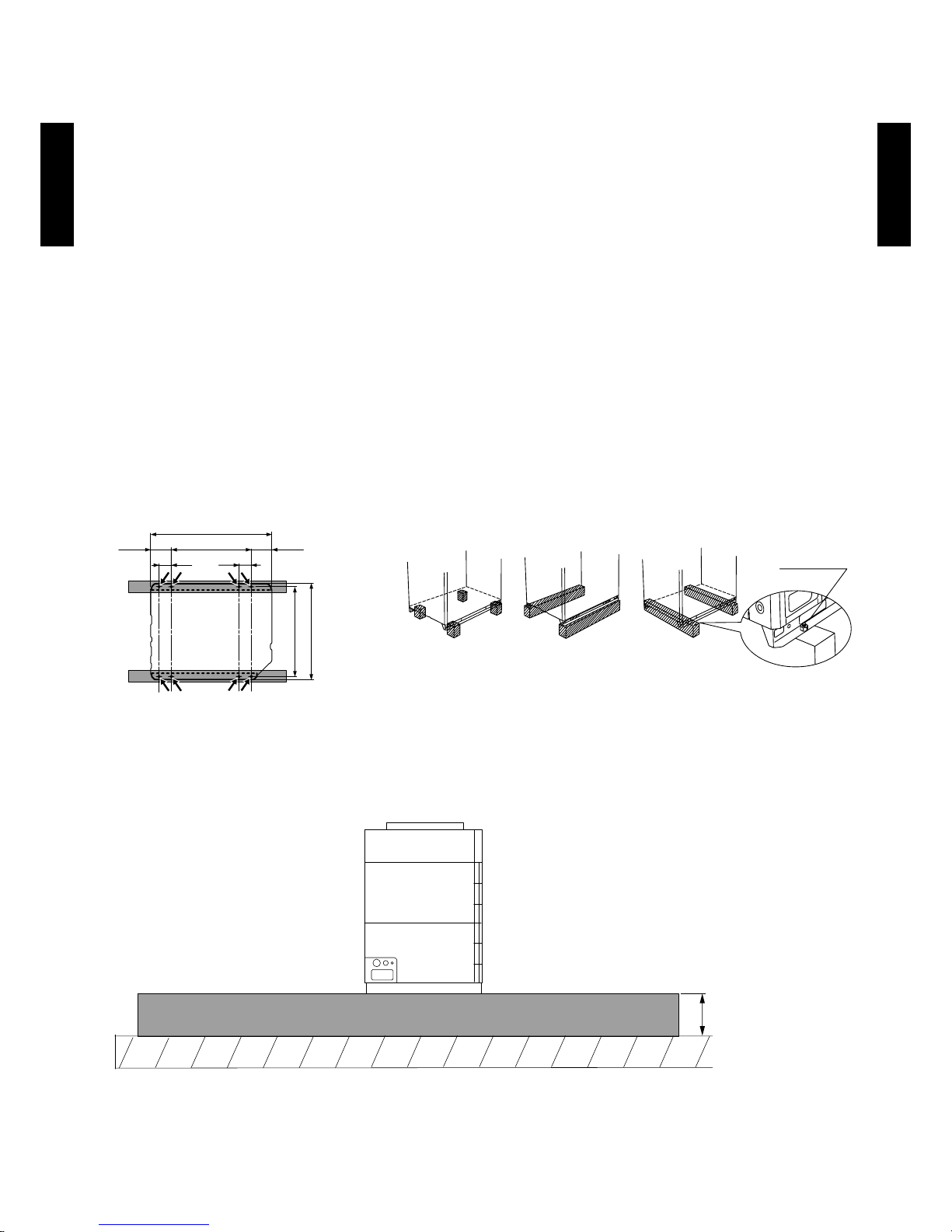
INSTALLATION (FOUNDATION)
Install the unit horizontally (within 3 degrees). •
Install 4 or more anchor bolts at the 8 locations indicated by arrows (Fig. A). •
Place the left and right anchor bolts at a distance further away than 610 mm. •
(Excluding the case where anchor bolts are installed at 8 locations.)
To minimize vibration, do not install the outdoor unit directly on the ground. Instead, install it on •
top of a rm platform (such as concrete block) (Fig. B).
Keep the height of foundation base over 200 mm from the oor surface (Fig. C). •
The foundation base should be able to support the product and the foot width of the product •
should be more than 46.5 mm.
Depending on the installation condition, vibration during the operation of the unit may cause •
noise and vibration.
Install vibration-proong materials (such as rubber pads). •
Consider the removal space of the connection piping when installing the foundation. •
• Secure the equipment rmly with anchor bolts, washers, and nuts.
More than
200mm
(Unit : mm)
Bottom view 8 - 12 x 17 (hole)
732
765
160
160610
930
80 80
Fig. A
Fig. C
*Do not use a four-cornersupport foundation.
Bolt (M10)
No good OK OK
Fig. B
Page 47

- (02 - 06) -
OUTDOOR UNIT
AO
A7 2-90LALT
OUTDOOR UNIT
AO
A7 2-90LALT
CENTER OF GRAVITY POSITION
Models : zAOA72LALT, AOA9 0L ALT
(Unit : mm)
● :
Center of gravity
Page 48
- (02 - 07) -
OUTDOOR UNIT
AO
A7 2-90LALT
OUTDOOR UNIT
AO
A7 2-90LALT
INSTALLATION PLACE3.
WHEN INSTALL NEAR BY LIMITED HEIGHT WALL3-1.
SINGLE AND MULTIPLE INSTALLATIONS
There are no restrictions on the height of the side wall.
●
Provide installation spaces L1 and L2 in accordance with the table below according to the
●
wall height (front side, rear side) conditions.
Provide installation spaces other than L1 and L2 in accordance with the conditions shown in
●
the gure below.
Ventilation resistance can be ignorable when the distance from a wall or product, etc. is
●
larger than 2m.
Wall height condition Necessary installation space
When H1 is 1500(mm) or less L1 ≥ 500 (mm)
When H1 is 1500(mm) or more L1 ≥ 500 + h1 ÷ 2 (mm)
When H2 is 500(mm) or less L2 ≥ 300 (mm)
When H2 is 500(mm) or more L2 ≥ 300 + h2 ÷ 2 (mm)
Caution
When installing the outdoor unit, pay attention to the following items.
To prevent stopping of operation by short circuit and worsening of performance and high pressure ●
protection, refer to the installation space shown in the figure and secure enough space.
Install in sufficient space considering the carrying in route, installation space, maintenance space, ●
passage of people, etc.
Do not place obstructions in the air flow outlet direction. If there is an obstruction in the outlet ●
direction, install an outlet duct.
When there is a wall in front of the unit, provide a space of 500mm or more as maintenance space. ●
When there is a wall at the side of the unit, provide a space of 30mm or more as maintenance ●
space.
An outdoor temperature of 35 degrees in air-conditioned operation is assumed for the installation ●
space in this item. If the outdoor temperature exceeds 35 degrees, provide a larger inlet space.
When installing, also consider the refrigerant piping space. ●
h1
1500
H1
L1
L2
500
h2
H2
30 mm
or more
30 mm
or more
<Front>
<Rear>
30 mm
or more
30 mm
or more
30 mm
or more
<Front>
<Rear>
30 mm
or more
<Side view>
<Top view>
Wall Wall
<Top view>
Front Rear
Page 49

- (02 - 08) -
OUTDOOR UNIT
AO
A7 2-90LALT
OUTDOOR UNIT
AO
A7 2-90LALT
WHEN INSTALL NEAR BY UNLIMITED HEIGHT WALL3-2.
SINGLE AND MULTIPLE INSTALLATIONS
There are no restrictions on the height of the wall.
●
The wall (without height restrictions) must not exist on the both sides (left / right) of outdoor
●
unit. Also, must not exist on the both sides (front / rear) of outdoor unit.
Provide installation spaces other than L3 in accordance with the conditions shown in the
●
gure below.
Ventilation resistance can be ignorable when the distance from a wall or product, etc. is
●
larger than 2m.
When installing with the REAR of the outdoor unit facing the wall side
z
Condition Necessary installation space
When B ≥ 400 (mm) L3 ≥ 200 (mm)
When 30 ≤ B < 400 (mm) L3 ≥ 200 + (400 - B) x 3 (mm)
Single installation Multiple installations
<Top view>
<Front>
<Rear>
300 mm
or more
200 mm
or more
200 mm
or more
<Front>
<Rear>
300 mm
or more
<Top view>
<Front>
<Rear>
300 mm
or more
B
L3
B
300 mm
or more
200 mm 200 mm
800 mm
or more
Example:
When B is made 200 mm
L3
>
=
200+(400-200)×3=800 mm
Page 50

- (02 - 09) -
OUTDOOR UNIT
AO
A7 2-90LALT
OUTDOOR UNIT
AO
A7 2-90LALT
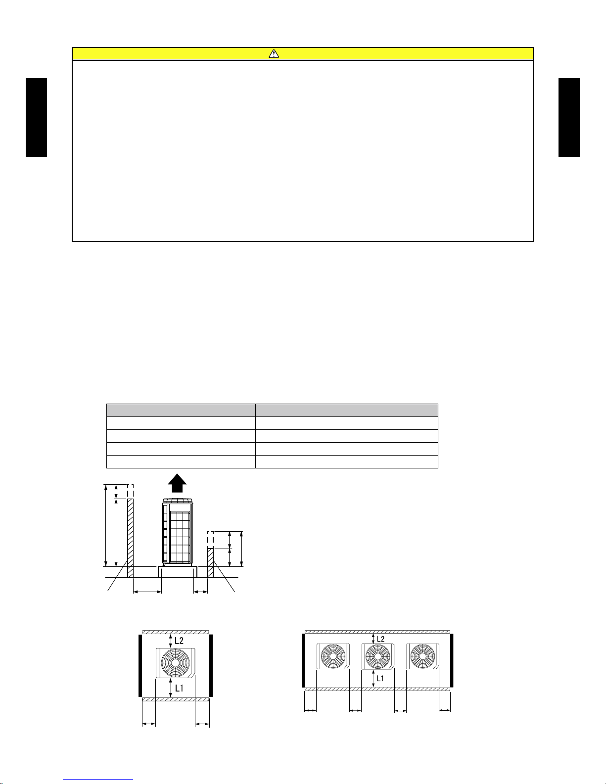
When there are obstacles above the product, keep the minimum installation height as shown
in the gure and install the outlet duct.
The efciency might decrease when the outlet duct etc. are installed.
When an outlet duct is not installed, install the product as shown below.
z
1) Make the ceiling height after setting 1m or greater.
2) Be sure there is no wall at the rear side.
3) When installing products adjacently, install up to 3 units.
WHEN THERE IS AN OBSTRUCTION ABOVE THE PRODUCT3-3.
500mm
or more
Outlet
duct
1000mm
or more
500mm
or more
front rear
Page 51

- (02 - 10) -
OUTDOOR UNIT
AO
A7 2-90LALT
OUTDOOR UNIT
AO
A7 2-90LALT
REFRIGERANT CIRCUIT4.
MODEL : AOA72LALT, AOA9 0 L ALT
Page 52

- (02 - 11) -
OUTDOOR UNIT
AO
A7 2-90LALT
OUTDOOR UNIT
AO
A7 2-90LALT
WIRING DIAGRAMS5.
MODEL : AOA72LALT, AOA9 0 L ALT
Page 53

- (02 - 12) -
OUTDOOR UNIT
AO
A7 2-90LALT
OUTDOOR UNIT
AO
A7 2-90LALT
CAPACITY COMPENSATION RATE FOR PIPE LENGTH 6.
AND HEIGHT DIFFERENCE
MODEL : AOA72LALT
COOLING
Pipe length (m)
5 7. 5 10 20 30 40 50 60 75
Height
difference
H
(m)
1
Indoor unit is
higher than
outdoor unit
30 - - - - 0.901 0.878 0.855
0.832 0.798
20 - - - 0.939 0.916 0.892 0.869
0.846 0.811
10 - - 0.978 0.954 0.931 0.907 0.884
0.860 0.825
7. 5 - 0.988 0.982 0.958 0.935 0.911 0.887
0.864 0.828
5 0.992 0.992 0.986 0.962 0.938 0.915 0.891
0.867 0.831
0 1.000 1.000 0.994 0.970 0.946 0.922 0.898
0. 874 0.838
2
Indoor unit is
lower than
outdoor unit.
-5 1.000 1.000 0.994 0.970 0.946 0.922 0.898
0. 874 0.838
-7. 5 - 1.000 0.994 0.970 0.946 0.922 0.898
0. 874 0.838
-10 - - 0.994 0.970 0.946 0.922 0.898
0. 874 0.838
-20 - - - 0.970 0.946 0.922 0.898
0. 874 0.838
-30 - - - - 0.946 0.922 0.898
0. 874 0.838
HEATING
Pipe length (m)
5 7. 5 10 20 30 40 50 60 75
Height
difference
H
(m)
1
Indoor unit is
higher than
outdoor unit
30 - - - - 0.977 0.966 0.956
0.946 0.930
20 - - - 0.987 0.977 0.966 0.956
0.946 0.930
10 - - 0.997 0.987 0.977 0.966 0.956
0.946 0.930
7. 5 - 1.000 0.997 0.987 0.977 0.966 0.956
0.946 0.930
5 1.000 1.000 0.997 0.987 0.977 0.966 0.956
0.946 0.930
0 1.000 1.000 0.997 0.987 0.977 0.966 0.956
0.946 0.930
2
Indoor unit is
lower than
outdoor unit.
-5 0.995 0.995 0.992 0.982 0.972 0.961 0.951
0. 9 41 0.925
-7. 5 - 0.993 0.990 0.980 0.970 0.959 0.949
0.939 0.923
-10 - - 0.987 0.977 0.967 0.956 0.946
0.937 0.921
-20 - - - 0.967 0.957 0.947 0.937
0.927 0.911
-30 - - - - 0.948 0.937 0.927
0.918 0.902
Outdoor unit
Indoor unit
Connec tion pipe
2 Indoor unit is lower than outdoor unit.
H
Indoor unit
Outdoor unit
Connec tion pipe
1 Indoor unit is higher than outdoor unit.
H
Height difference H
Page 54

- (02 - 13) -
OUTDOOR UNIT
AO
A7 2-90LALT
OUTDOOR UNIT
AO
A7 2-90LALT
MODEL : AOA9 0 L ALT
Outdoor unit
Indoor unit
Connec tion pipe
2 Indoor unit is lower than outdoor unit.
H
Indoor unit
Outdoor unit
Connec tion pipe
1 Indoor unit is higher than outdoor unit.
H
Height difference H
COOLING
Pipe length (m)
5 7. 5 10 20 30 40 50 60 75
Height
difference
H
(m)
1
Indoor unit is
higher than
outdoor unit
30 - - - - 0.898 0.874 0.850 0.826 0.790
20 - - - 0.938 0.913 0.889 0.864 0.840 0.803
10 - - 0.978 0.953 0.928 0.903 0.879 0.854 0.817
7. 5 - 0.988 0.982 0.957 0.932 0.907 0.882 0.858 0.820
5 0.992 0.992 0.986 0.961 0.935 0.911 0.886 0.861 0.823
0 1.000 1.000 0.994 0.969 0.943 0.918 0.893 0.868 0.830
2
Indoor unit is
lower than
outdoor unit.
-5 1.000 1.000 0.994 0.969 0.943 0.918 0.893 0.868 0.830
-7. 5 - 1.000 0.994 0.969 0.943 0.918 0.893 0.868 0.830
-10 - - 0.994 0.969 0.943 0.918 0.893 0.868 0.830
-20 - - - 0.969 0.943 0.918 0.893 0.868 0.830
-30 - - - - 0.943 0.918 0.893 0.868 0.830
HEATING
Pipe length (m)
5 7. 5 10 20 30 40 50 60 75
Height
difference
H
(m)
1
Indoor unit is
higher than
outdoor unit
30 - - - - 0.977 0.966 0.956 0.946 0.930
20 - - - 0.987 0.977 0.966 0.956 0.946 0.930
10 - - 0.997 0.987 0.977 0.966 0.956 0.946 0.930
7. 5 - 1.000 0.997 0.987 0.977 0.966 0.956 0.946 0.930
5 1.000 1.000 0.997 0.987 0.977 0.966 0.956 0.946 0.930
0 1.000 1.000 0.997 0.987 0.977 0.966 0.956 0.946 0.930
2
Indoor unit is
lower than
outdoor unit.
-5 0.995 0.995 0.992 0.982 0.972 0.961 0.951 0.941 0.925
-7. 5 - 0.993 0.990 0.980 0.970 0.959 0.949 0.939 0.923
-10 - - 0.987 0.977 0.967 0.956 0.946 0.937 0.921
-20 - - - 0.967 0.957 0.947 0.937 0.927 0.911
-30 - - - - 0.948 0.937 0.927 0.918 0.902
Page 55

- (02 - 14) -
OUTDOOR UNIT
AO
A7 2-90LALT
OUTDOOR UNIT
AO
A7 2-90LALT
PIPE SIZE SELECTION & LIMITATION7.
MODEL : AO
A72LALT, AOA9 0 L ALT
ADDITIONAL CHARGE CALCULATION8.
MODEL : AO
A72LALT, AOA9 0 L ALT
Refrigerant charge
z
Refrigerant type R410A
Refrigerant amount g 11, 20 0
Refrigerant pipe size
[mm (in.)]
Piping length
Standard ~20 m 30 m 40 m 50 m 60 m 70 m 75 m g/m
Liquid
Gas
12.70 (1/2)
25.40 (1)
None 1,100 g 2,200 g 3,300 g 4,400 g 5,500 g 6,050 g 110 g/m
Size down ~20 m 30 m 40 m 50 m 60 m 70 m 75 m g/m
Liquid
Gas
12.70 (1/2)
22.22 (7/8)
None 1,100 g 2,200 g 3,300 g 4,400 g 5,500 g 6,050 g 110 g/m
Size up ~20 m 30 m 40 m 50 m g/m
Liquid
Gas
12.70 (1/2)
28.58 (9/8)
None 1,100 g 2,200 g 3,300 g 110 g/m
Size down Standard Size up
Pipe diameter
Liquid pipes 12.70 (1/2)
[mm (in.)] Gas pipes
22.22
(7/8)
25.40
(1)
28.58
(9/8)
Piping length
Max. piping length (L1)
(Max. chargeless length)
[m (m)] 75 (20) 75 (20) 50 (20)
Min. piping length (L1) [m] 5
Max. height difference (H1)
<Indoor unit to outdoor unit>
[m]
30
L1
H1
Page 56

- (02 - 15) -
OUTDOOR UNIT
AO
A7 2-90LALT
OUTDOOR UNIT
AO
A7 2-90LALT
AIR FLOW9.
MODEL : AOA72LALT
Cooling
z
Heating
z
MODEL : AOA9 0 L ALT
Cooling
z
Heating
z
Number of
rotations
(r.p.m)
Air ow
730
m
3
/h 9300
l/s 2583
CFM 5474
Number of
rotations
(r.p.m)
Air ow
730
m
3
/h 9300
l/s 2583
CFM 5474
Number of
rotations
(r.p.m)
Air ow
830
m
3
/h 10700
l/s 2972
CFM 6298
Number of
rotations
(r.p.m)
Air ow
840
m
3
/h 108 00
l/s 3000
CFM 6357
Page 57

- (02 - 16) -
OUTDOOR UNIT
AO
A7 2-90LALT
OUTDOOR UNIT
AO
A7 2-90LALT
OPERATION NOISE10.
NOISE LEVEL CURVE10-1.
MODEL : AOA72LALT
Octave ba nd sound p ressur e level, dB:(0 dB= 0.00 02µbar)
Octave ba nd cente r frequency,Hz
80
70
60
50
40
30
20
10
0
63 125 250 50 0 1,000 2 ,000 4 ,000 8,000
NC-65
NC-60
NC-55
NC-50
NC-45
NC-40
NC-35
NC-30
NC-25
NC-20
NC -15
Cooling
z
Octave ba nd sound p ressur e level, dB:(0 dB= 0.00 02µbar)
Octave ba nd cente r frequency,Hz
80
70
60
50
40
30
20
10
0
63 125 250 50 0 1,000 2 ,000 4 ,000 8,000
NC-65
NC-60
NC-55
NC-50
NC-45
NC-40
NC-35
NC-30
NC-25
NC-20
NC -15
Heating
z
Octave ba nd sound p ressur e level, dB:(0 dB= 0.00 02µbar)
Octave ba nd cente r frequency,Hz
80
70
60
50
40
30
20
10
0
63 125 250 50 0 1,000 2 ,000 4 ,000 8,000
NC-65
NC-60
NC-55
NC-50
NC-45
NC-40
NC-35
NC-30
NC-25
NC-20
NC -15
Heating
z
Octave ba nd sound p ressur e level, dB:(0 dB= 0.00 02µbar)
Octave ba nd cente r frequency,Hz
80
70
60
50
40
30
20
10
0
63 125 250 50 0 1,000 2 ,000 4 ,000 8,000
NC-65
NC-60
NC-55
NC-50
NC-45
NC-40
NC-35
NC-30
NC-25
NC-20
NC -15
MODEL : AOA9 0 L ALT
Cooling
z
Page 58

- (02 - 17) -
OUTDOOR UNIT
AO
A7 2-90LALT
OUTDOOR UNIT
AO
A7 2-90LALT
SOUND LEVEL CHECK POINT10-2.
Microphone
1 m
1 m
Page 59

- (02 - 18) -
OUTDOOR UNIT
AO
A7 2-90LALT
OUTDOOR UNIT
AO
A7 2-90LALT
ELECTRIC CHARACTERISTICS11.
*1) The maximum current is the total current of indoor unit and outdoor unit.
*2) Wiring spec. :
Selected sample
(Selected based on Japan Electrotechnical Standard and Codes Committee E0005)
Model AOA72LALT AOA90LALT
Power supply
Voltage V 400
Frequency Hz 50
*1) Max. operating current A 22.8 25.8
Starting current A 9.6 12.5
Breaker
MCCB
Capacity
A 30
ELCB
Leakage current
30mA
0.1sec or less
Outdoor unit power
supply cable
Power supply cable
mm
2
6
Ground wire
mm
2
6
Page 60

- (02 - 19) -
OUTDOOR UNIT
AO
A7 2-90LALT
OUTDOOR UNIT
AO
A7 2-90LALT
SAFETY DEVICES12.
Protection form
Model
AOA72LALT AOA90LALT
Circuit protection
Fuse (Main PCB)
AC400V 15A
AC250V 3.15A
Protector (FILTER PCB) AC500V 25A
Indoor unit protection Fuse AC250V 20A
Compressor protection
Thermal protection program
(Compressor temp.)
OFF : 112°C
ON : 80°C
Thermal protection program
(Discharge temp.)
OFF : 115°C
ON : After 7 minutes.
High pressure protection Pressure switch
OFF : 4.2MPa
ON : 3.2MPa
Low pressure protection Pressure sensor
OFF : 0.02MPa
ON : 0.05MPa
Fan motor protection Thermal protection program
OFF :100
+15
°C
-10
ON : 95
+15
°C
-10
Page 61
- (02 - 20) -
OUTDOOR UNIT
AO
A7 2-90LALT
OUTDOOR UNIT
AO
A7 2-90LALT
EXTERNAL INPUT & OUTPUT13.
EXTERNAL INPUT13-1.
ON/OFF of the "Low noise mode" and "Peak cut mode" functions can be specied by external
signal.
LOW NOISE MODE
On-site work like the following also reduces the operating sound of the outdoor unit from the •
normal sound.
The air conditioner is set to the "Low noise mode" by applying the contact input of a commercial
timer or ON/OFF switch to a connector on the outdoor control PC board.
* Performance may drop depending on the outside air temperature condition, etc.
Circuit diagram example
z
Use the following parts and construct a circuit like that shown above. •
Input Signal •
ON : Low noise mode / OFF : Normal operation
* Set the "Low noise mode" level by "Push switch" on the outdoor control PC board.
Parts (Optional)
z
Model name
UT Y-XWZ X Z2
Wire (External input)
Input Output Connector Remarks
Low noise mode ― CN131
See external
input/output settings
for details.
Peak cut mode ― CN131
― Error status CN136
― Compressor status CN136
― Base heater CN115
Outdoor
control PC board
Connected unit
Connector
1
2
3
Signal
Field supply
* Make the distance from the PC board to the connected unit within 10 m.
Surely insulate with
insulation tape etc. since
this wire is not used.
*10 m
Red
White
Black
Vcc
R
SW
Vcc
Power
supply
ON
OFF
ON
OFF
Input Signal
Low noise mode
1) Power supply
●Voltage (Chart sign=Vcc) : DC 5V to 24V
●The current capacity : About 100m A
2) Switch (Char t sign=SW)
● Toggle switch or Rocker switch, etc : Switch which maintains the
states.
● Prep ar e swit ch es w hi ch a re enoug h capa ble for DC 10m A
current or more
3) Resistance (Chart sign=R)
●Adjust the resistance for current to about DC 10mA
(Example)
●In case of Vcc= DC 5V : Rated resistance value 470Ω 1/4W
●In case of Vcc= DC 12V : Rated resistance value 1kΩ 1/4W
●In case of Vcc= DC 24V : Rated resistance value 2.2kΩ 1/4W
Page 62

- (02 - 21) -
OUTDOOR UNIT
AO
A7 2-90LALT
OUTDOOR UNIT
AO
A7 2-90LALT
PEAK CUT MODE
Operation that suppressed the current value can be performed by means of the following on- •
site work. The air conditioner is set to the Peak cut mode by applying the contact input of a
commercial ON/OFF switch to a connector on the outdoor control PC board.
Circuit diagram example
z
Outdoor
control PC board
Connected unit
Connector
1
2
3
Signal
Field supply
* Make the distance from the PC board to the connected unit within 10 m.
Surely insulate with
insulation tape etc. since
this wire is not used.
*10 m
Red
White
Black
Vcc
R
SW
Vcc
Power
supply
Use the following parts and construct a circuit like that shown above. •
Input Signal∙∙∙ON : Peak cut mode/OFF : Normal operation •
*Set the "Peak cut mode" level by "Push switch" on the outdoor control PC board.
ON
OFF
ON
OFF
Input Signal
Peak cut mode
Parts (Optional)
z
Model name
UT Y-XWZ X Z2
Wire (External input)
1) Power supply
●Voltage (Chart sign=Vcc) : DC 5V to 24V
●The current capacity : About 100m A
2) Switch (Char t sign=SW)
● Toggle switch or Rocker switch, etc : Switch which maintains the
states.
● Prep ar e swit ch es w hi ch a re enoug h capa ble for DC 10m A
current or more
3) Resistance (Chart sign=R)
●Adjust the resistance for current to about DC 10mA
(Example)
●In case of Vcc= DC 5V : Rated resistance value 470Ω 1/4W
●In case of Vcc= DC 12V : Rated resistance value 1kΩ 1/4W
●In case of Vcc= DC 24V : Rated resistance value 2.2kΩ 1/4W
Page 63

- (02 - 22) -
OUTDOOR UNIT
AO
A7 2-90LALT
OUTDOOR UNIT
AO
A7 2-90LALT
EXTERNAL OUTPUT13-2.
ERROR STATUS OUTPUT
An air conditioner error status signal can be output by means of the following on-site work. •
Circuit diagram example
z
Parts (Optional)
z
Model name
UT Y-XWZ X Z2
Wire (External output)
Signal
Outdoor
control PC board
Connected unit
Connector
1
2
3
Field supply
* Make the distance from the PC board to the connected unit within 10 m.
Surely insulate with
insulation tape etc. since
this wire is not used.
*10 m
Red
White
Black
Vcc+Vcc
Power
supply
+
-
Load
Error
Normal
ON
OFF
Error status
Output signal
1) Power supply
●Voltage (Chart sign=Vcc) : DC 24V or less
2) Load
● Load : DC 20mA or less
Page 64

- (02 - 23) -
OUTDOOR UNIT
AO
A7 2-90LALT
OUTDOOR UNIT
AO
A7 2-90LALT
COMPRESSOR STATUS OUTPUT
Compressor operation status signal can be output by means of the following on-site work. •
Circuit diagram example
z
Parts (Optional)
z
Model name
UT Y-XWZ X Z2
Wire (External output)
Signal
Outdoor
control PC board
Connected unit
Connector
1
2
3
Field supply
* Make the distance from the PC board to the connected unit within 10 m.
Surely insulate with
insulation tape etc. since
this wire is not used.
*10 m
Red
White
Black
Vcc
+
+
-
Load
Vcc
Power
supply
ON
OFF
Operation
Stop
Compressor
Output signal
status
1) Power supply
●Voltage (Chart sign=Vcc) : DC 24V or less
2) Load
● Load : DC 20mA or less
Page 65

- (02 - 24) -
OUTDOOR UNIT
AO
A7 2-90LALT
OUTDOOR UNIT
AO
A7 2-90LALT
BASE HEATER
This output the signal when temperature goes down 2°C, and release at 4°C. •
Circuit diagram example
z
Parts
z
(Optional)
Model name
UT Y-XWZ X Z4
Wire (External output)
ON
OFF
Operation
Stop
Heater
Output signal
status
*1: Connect to pin 1 and pin 3. No connection pin2 and pin4.
*2: The allowable power consumption is 25W or less.
*3: The case of using load more than 25W, have to using another method for preparation is Contactor
or Relay etc.
1
2
3
4
Connector
(Black)
AC240V
Base heater
*2
*1
connected unit
P. C. B
1
2
3
4
Connector
(Black)
AC240V
Base heater
*3
*1
connected unit
P. C. B
Page 66
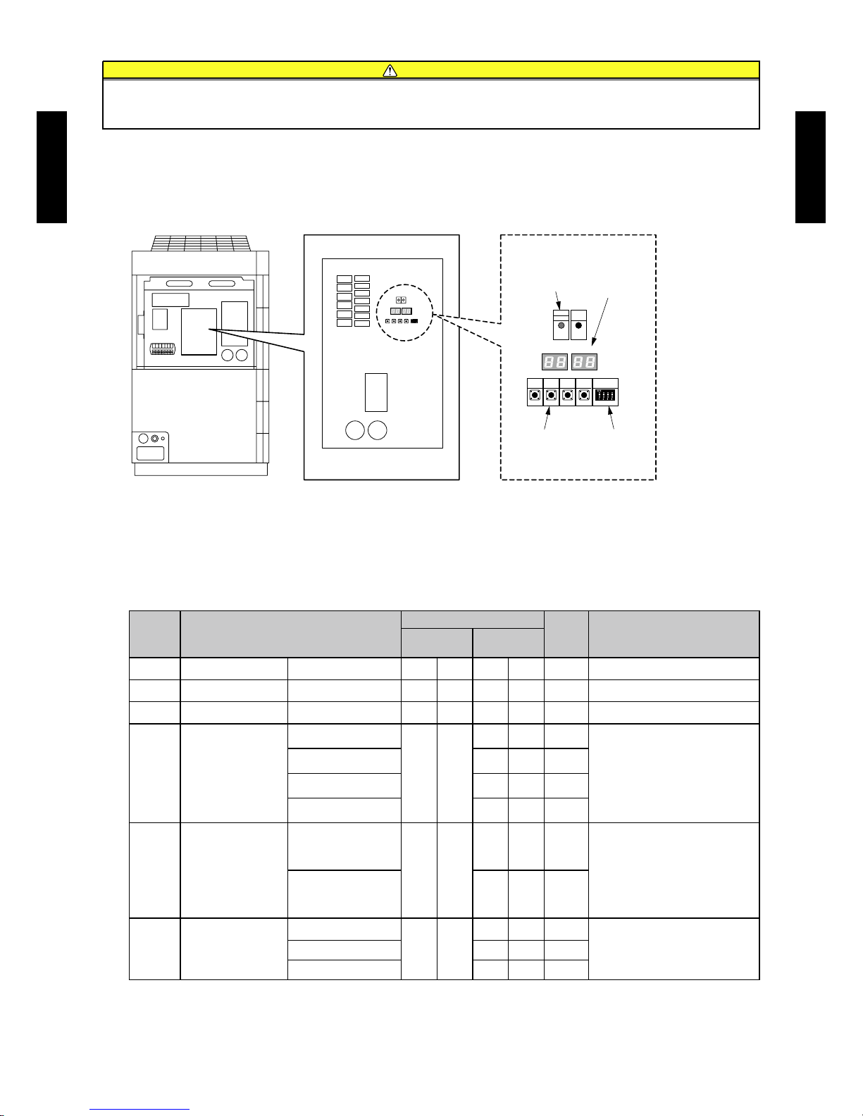
- (02 - 25) -
OUTDOOR UNIT
AO
A7 2-90LALT
OUTDOOR UNIT
AO
A7 2-90LALT
FUNCTION SETTING14.
FIELD SETTING SWITCHES14-1.
Remove the front panel of the outdoor unit and the cover of the electrical component box to
access the print circuit board of the outdoor unit.
Print circuit board switches for various settings and LED displays are shown in the gure.
FUNCTION SETTINGS14-2.
Various functions can be set. Follow the setting method described in 14-2-1. to set as per the
requirement. Perform these settings after the indoor unit stops.
Table. Settings List
No Setting Item
7 segment LED
Facto ry
setting
Content
First 2
digits
Last 2
digits
0 Forbidden 0 0 0 0
●
13 Forbidden 1 3 0 0
●
14 Forbidden 1 4 0 0
●
30
Peak cut mode :
Energy-saving level
Level 1 (stop operation)
3 0
0 0
Settings for limited capacity
operation or stopping the compressor
can be done.
Settings will enable when input signal
has been entered the external input
terminal “CN131”.
Level 2 (Limited at 50%) 0 1
Level 3 (Limited at 75%) 0 2
●
Level 4 (100%) 0 3
41
Low noise mode :
Operation setting
Normal operation
4 1
0 0
●
Noise of the outdoor unit can be kept
low. Set Low noise operation, which
will enable when the input signal
has been entered the external input
terminal “CN131”.Low noise operation 0 1
42
Low noise mode :
Operation level setting
Level 1
4 2
0 0
●
This item allows you to congure the
noise level when the unit operates
under low noise operation level.
Level 2 0 1
Forbidden 0 2
Caution
Discharge the static electricity from your body before setting up the DIP switches.
Never touch the terminals or the patterns on the parts that are mounted on the board.
POWER
LED105 LED104
SW101
ERROR
MODE
LED101
(GREEN)
MODE
/EXIT
PUMP
DOWN
SELECT
ENTER
SW107
SW108
SW109 SW102
LED102
(RED)
Outdoor unit printed circuit board
DIP switch
LED Lamp
7 Segment
LED Lamp
Push button
Page 67

- (02 - 26) -
OUTDOOR UNIT
AO
A7 2-90LALT
OUTDOOR UNIT
AO
A7 2-90LALT
SETTING METHOD14-2-1.
(1) Turn on the power of the outdoor
unit and enter standby mode.
POWER/MODE lamp lights up.
(ERROR Lamp is off.)
(2) Press the MODE/EXIT button (SW107) once.
LED105 LED104 LED105 LED104
(3) Press the SELECT button (SW108), and display “F2” on the LED104.
*1 *1
LED105 LED104 LED105 LED104 LED105 LED104 LED105 LED104
(The display of the LED104 changes each time the SELECT button is pressed.)
(Function mode)
(Setting mode)
*1: The “F1” and “F9” modes are used for maintenance, so do not set them in regular operation.
(4) When “F2” appears on the LED104, press the ENTER button (SW109).
LED105 LED104 LED105 LED104
(5) Referring to the Settings List shown below, press the SELECT button (SW108) and display
the code number of the mode you want to set on the LED105.
Ex.) To select the Low noise operation setting.
LED105 LED104 LED105 LED104
Next, press the ENTER button (SW109), and conrm the selection of the mode you want to set.
LED105 LED104 LED105 LED104
A ashing display on the LED105 changes to an illuminated display, and an illuminated display
on the LED104 changes to ashing display.
POWER
LED105 LED104
SW101
ERROR
MODE
LED101
(GREEN)
MODE
/EXIT
PUMP
DOWN
SELECT
ENTER
SW107
SW108
SW109 SW102
LED102
(RED)
POWER/MODE Lamp: ON
ERROR Lamp: OFF
7 Segment
LED Lamp: OFF
DIP switch
(Do not operate.)
PUMP DOWN button
(Do not operate in this chapter.)
ENTER button
SELECT button
MODE/EXIT button
Page 68

- (02 - 27) -
OUTDOOR UNIT
AO
A7 2-90LALT
OUTDOOR UNIT
AO
A7 2-90LALT
(6) Again, referring to the Settings List shown below, press the SELECT button (SW108), and
display the code number of the function you want to set on the LED104.
Ex.) To select the Low noise operation setting.
LED105 LED104 LED105 LED104
Next, press the ENTER button (SW109), and conrm the selection of the mode you want to set.
LED105 LED104 LED105 LED104
A ashing display on the LED104 changes to an illuminated display. Settings are complete with
the procedures described above.
(7) To set another function, press the ENTER button (SW109) in the setting completed status
shown in step (5) above.
LED105 LED104 LED105 LED104
Repeat steps (5) and (6) above to set other functions.
When all settings are complete, perform the operation described in sttep (8) above to exit.
(8) To exit FUNCTION SETTING, press the ENTER button (SW109) in the setting completed
status shown in step (6) above.
LED105 LED104 LED105 LED104
*2
Then, press the MODE/EXIT button (SW107) to exit FUNCTION SETTING MODE.
LED105 LED104 LED105 LED104
*2: 5 seconds after, even if ENTER button (SW109) is not pressed,
LED105 changes to a ashing display automatically.
Page 69

- (02 - 28) -
OUTDOOR UNIT
AO
A7 2-90LALT
OUTDOOR UNIT
AO
A7 2-90LALT
PEAK CUT MODE14-2-2.
ENERGY SAVING LEVEL SETTING
This operation saves the capacity and reduces the power consumption.
Energy-saving level can be set by adding the contact input of commercially available ON-OFF
change-over switch to CN131 connector (external contact input sold separately) located on the
control board of outdoor unit.
Setting method
z
Perform the following settings according to the function setting •
method described in previous section.
Set “F2” with “1: FUNCTION SETTING”.
Set “2: Set the rst two digits of setting item” to “30”.
Set “3: Set the last two digits of setting item” to “00 (Level 1)” “03 (Level 4)”.
* Factory default setting is “02 (Level 3)”.
LOW NOISE MODE14-2-3.
OPERATION SETTING
Outdoor unit is operated in such a way that noise level is reduced below normal level.
Low noise operation level is possible by adding the contact input of commercially available timer,
or ON-OFF change-over switch to CN131 connector (external contact input sold separately)
located on the control board of outdoor unit.
Setting method
z
• Perform the following settings according to the function setting
method described in previous section.
Set “F2” in “1: FUNCTION SETTING”.
Set “2: Set the rst two digits of setting item” to “41”.
Set “3: Set the last two digits of setting item” to “00 (Normal Operation)” or
“01 (Low Noise Operation)”.
* Factory default setting is “00 (Normal Operation)”.
OPERATION LEVEL SETTING
Noise level of low noise operation can be set.
Setting method
z
• Perform the following settings according to the function setting
method described in previous section.
Set “F2” in “1: FUNCTION SETTING”.
Set “2: Set the rst two digits of setting item” to “42”.
Set “3: Set the last two digits of setting item” to “00 (Level 1)” “01 (Level 2)”.
* Factory default setting is “00 (Level 1)”.
LED105
LED104
Example) For setting energy-saving level
to 50% (Level 2).
LED105
LED104
Example) For setting low noise
operation.
LED105
LED104
Example) For setting operation noise
level to Level 2.
Page 70

- (02 - 29) -
OUTDOOR UNIT
AO
A7 2-90LALT
OUTDOOR UNIT
AO
A7 2-90LALT
OPTIONAL PARTS15.
Exterior Parts name Model No. Summary
External connect
kit
UTY - XWZXZ2
Use to operate the External input
and output function of Outdoor
unit.
External connect
kit
UTY - XWZXZ4
Use to operate the External input
and output function of Outdoor
unit.
Page 71

- (02 - 30) -
OUTDOOR UNIT
AO
A7 2-90LALT
OUTDOOR UNIT
AO
A7 2-90LALT
LOCALLY PROCURED PARTS16.
AIR DISCHARGE DUCT16-1.
PRECAUTION
All the components/parts such as the duct, frame, and screws are to be locally procured.
●
Do not install the duct where seasonal wind blow directly against to the discharge port.
●
Install so that the static pressure of the air ow path
●
, including the duct is 33Pa or less.
Note that installation of the duct increases the height of the cabinet.
●
If installation space may narrow, like as consecutive unit layout, be sure to x the duct to the
●
unit before placing the unit.
When the duct is installed, the noise may become louder.
●
DUCT LAYOUT EXAMPLE
Dimension C
(Minimum) (Maximum)
862 928
Caution
Make the height A of the duct opening section 500mm or greater. ●
Make the height B of the duct, excluding the flange 500mm or greater. ●
Make the width (dimension C) of the duct within the range of the table shown above. ●
Provide a Chamfer or round the corner at the air flow path. ●
Design the duct weight with 100kg or less as the standard. ●
Design the duct so that maintenance of the motor is possible. ●
(Unit : mm)
Chamfer or a round the corner
500 500
114
1576
Page 72

- (02 - 31) -
OUTDOOR UNIT
AO
A7 2-90LALT
OUTDOOR UNIT
AO
A7 2-90LALT
DUCT INSTALLATION PROCEDURE
Remove the top panel from the cabinet, and
●
make a ø6mm hole in each dowel of the top
panel. (9 dowels in total of the right and left
ones)
After drilling a hole in the dowel of the top panel,
●
fasten the duct to the ø5 tapping screw size hole
at the bottom.
Caution
Use ø5 tapping screws having a thread length of
●
10 to 20 mm.
Do not make holes anywhere other than the
●
dowels.
Otherwise, damage to the internal parts will
●
cause performance degradation or trouble.
Caution
Presence of a gap in the junction may cause performance
●
degradation.
Cover to close a gap(s).
●
To prevent an air leakage, close a gap in the chamfered
●
area with a steel plate or the like.
(Unit : mm)
Example of Installation
Fan guard
Top panel
Dowel
Frame
Duct
Chamfered
area
Dowel
Drilling position
Page 73
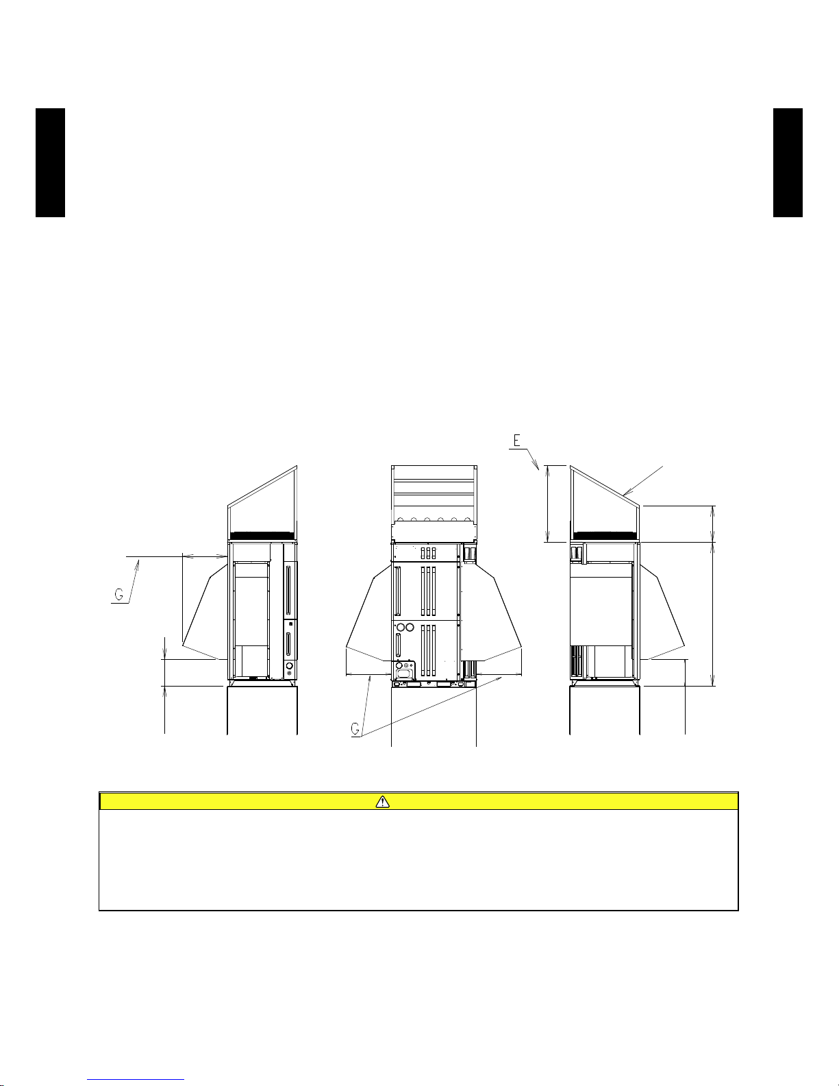
- (02 - 32) -
OUTDOOR UNIT
AO
A7 2-90LALT
OUTDOOR UNIT
AO
A7 2-90LALT
SNOW HOOD16-2.
In cold or snowy area, install inlet and outlet hood in order to maintain stable operation and
avoid snow damage.
PRECAUTION
All the components or parts such as the snow hood, frame, and screws are to be locally
●
procured.
Before snow hood installation, snow protection foundation must be installed as shown
●
bellow.
Height of snow protection foundation should be at least twice higher than expected snow
●
accumulation. Width of foundation should not be exceed the unit.
Do not install the snow hood not to blow directly against to the hood.
●
Note that installation of the snow hood increases the height of the cabinet.
●
If space for cabinet installation is tight because of the consecutive installation of equipment,
●
install the snow hood before the cabinet.
When the snow hood is installed, the noise may become louder.
●
EXAMPLE OF INSTALLING SNOW HOOD
Caution
Make the width G of the side of the snow hood 500mm or greater. ●
Provide an ample slope so that snow will not accumulate on the top of the snow hood. At this time, ●
do not make the direction of the slope such that the front becomes the bottom so that the snow will
not fall off at the front.
Make the front opening section E of the snow hood 600mm or greater. ●
(Unit : mm)
500500
500
290
600
4001576
290
Snow
protection
foundation
Snow
protection
foundation
Snow
protection
foundation
Provide a slope
Page 74

- (02 - 33) -
OUTDOOR UNIT
AO
A7 2-90LALT
OUTDOOR UNIT
AO
A7 2-90LALT
Caution
Use ø5 tapping screws having a thread length of 10 to 20mm.
●
Do not remove any screws from where a circle is not marked.
●
Do not make a hole in the dowels where a circle is not marked. Otherwise, damage to the internal
●
parts will cause performance degradation or trouble.
SNOW HOOD INSTALLATION PROCEDURE
Installing the upper part of snow hood
z
The upper part of snow hood can be installed in the same manner as for the duct. For
●
details such as where to x it, see the duct installation procedure.
Using the xing positions on the top panel, install the components such as the frame,
●
column, front panel, top panel, and rear panel.
Installing the sides of snow hood
z
Before starting snow hood installation, remove the screws from the external net to remove
●
the net.
Install the snow hood, using the screw holes shown in the gure on the next page.
●
Remove the screws from where circles are marked in the gure, and make a ø4.6mm hole
●
in each dowel.
Page 75

- (02 - 34) -
OUTDOOR UNIT
AO
A7 2-90LALT
OUTDOOR UNIT
AO
A7 2-90LALT
SCREW POSITIONS ON THE SIDES OF SNOW HOOD
NOTES ON INSTALLING SNOW HOOD
Left-side View Right-side ViewFront View
Rear View
Chamfered area
Notch the upper part of
snow hood so that it can be
mounted in place avoiding
the column.
Cover with a plate so there is
no gap.
Since there is the head
of the screws at this part,
cut a notch in the ange
of the snow hood
Install the snow
protection
foundation for
the inlet not to be
buried in snow.
To avoid snow accumulation on the
snow protection foundation, make the
foundation as wide as the cabinet.
Be careful that
the ange of snow
hood does not get
onto the stepped
area.
Make holes in the rear
panel so as to provide
good ventilation.
Drilling holes in 20% or
more of the rear panel is
recommended.
Snow protection
foundation
(Unit : mm)
(Unit : mm)
Page 76

- (02 - 35) -
OUTDOOR UNIT
AO
A7 2-90LALT
OUTDOOR UNIT
AO
A7 2-90LALT
CENTRAL DRAIN PAN16-3.
HOW TO INSTALL CENTRAL DRAIN PAN
All the components/parts such as the central drain pan and metal ttings are to be locally
●
procured.
Note that the refrigerant pipe cannot be come out of the bottom.
●
Do not mount the unit on an object which must not be wetted.
●
When humidity is high or the drain outlet is clogged, dew drops may fall from the central
●
drain pan.
Do not use the central drain pan in a cold region where the drain pipes may be frozen.
●
If hoses or sockets are to be used during installation, install the foundation as shown in the
●
gure below.
Do not use in cold regions. The drain pipe may freeze.
●
DRAIN PAN INSTALLATION PROCEDURE
First make screw holes in the dowels of base feet in the above gure. (8
dowels in total of the front and rear ones)
Secure the central drain pan by tightening the screws into the holes.
Cabinet
If a pipe or the like is to be used for
draining water from the central drain pan,
provide space large enough for working
and maintenance.
(Recommended height of foundation: 200
mm or more)
If hoses and sockets are to be used,
prevent a gap in their junctions by rmly
sealing them up
Drain pan
Foundation
Foundation
Dowel (at 4 positions in total)
(Unit : mm)
(Unit : mm)
Page 77

- (02 - 36) -
OUTDOOR UNIT
AO
A7 2-90LALT
OUTDOOR UNIT
AO
A7 2-90LALT
NOTES ON INSTALLING CENTRAL DRAIN PAN
Make sure to design and install drain pan to cover the all drain hole on base completely.
●
The gap between drain pan and base should be less than 2mm.
●
Be careful of the foot place during the working or design process.
●
If the foundation or foot place makes working difcult, the metal ttings should be used as
●
shown below.
Keep in mind that a drain pan not having the recommended outside dimensions can cause a
●
water leakage or cannot be installed.
Gaps other than the drain holes cause a water leakage. Completely close all the gaps in the
●
bottom and sides by welding.
No gap
Drain pan
No gap
10.8
60.7
10.8
60.7
Central drain pan
Front View
The central drain pan shall have
the width of this value or more.
795 or more
672
38
59
38
Central
drain pan
Left-side View
Base
The central drain pan shall have
the height of this value or more.
620 or more
16 or less
Foot place
46 or less
Metal ttings
Use metal ttings if necessary.
(Unit : mm)
 Loading...