

Fujitsu AU*A45LCLU, AO*A45LBTL, AO*A45LCTL, AU*A54LCLU, AO*A54LCTL Design & Technical Manual
Page 1

DESIGN & TECHNICAL MANUAL
SINGLE
INDOOR
OUTDOOR
AOA45LBTL
AUA45LCLU
AUA54LCLU
AOA45-54LCTL
AIR CONDITIONER
Cassette type
Page 2

1. INDOOR UNIT
D2D_AU041E/04
2011.03.01
CASSETTE TYPE :
AUA45LCLU
AUA54LCLU
Page 3

- (3) -
CASSETTE TYPE
AU
A45-54LC
CASSETTE TYPE
AU
A45-54LC
CONTENTS
1. INDOOR UNIT
1. FEATURE
............................................................................................................ 01 - 01
2. WIRED REMOTE CONTROLLER
................................................... 01 - 04
3. SPECIFICATIONS
........................................................................................ 01 - 06
4. DIMENSIONS
................................................................................................... 01 - 08
5. WIRING DIAGRAMS
.................................................................................. 01 - 10
6. CAPACITY TABLE
........................................................................................01 - 11
6-1. COOLING CAPACITY
.................................................................................01 - 11
6-2. HEATING CAPACITY
................................................................................. 01 - 13
7. FAN PERFORMANCE
.............................................................................. 01 - 15
7-1. AIR VELOCITY DISTRIBUTION
............................................................... 01 - 15
7-1-1. STANDARD MODE .................................................................................. 01 - 15
7-1-2. SPECIAL UPWARD MODE ..................................................................... 01 - 19
7-2. AIR FLOW
.................................................................................................... 01 - 20
7-2-1. 4-WAY OUTLET ....................................................................................... 01 - 20
7-2-2. 3-WAY OUTLET ....................................................................................... 01 - 21
7-3. FRESH AIR
................................................................................................... 01 - 22
7-4. DUCT CONNECTION
................................................................................. 01 - 23
8. OPERATION NOISE
................................................................................... 01 - 25
8-1. NOISE LEVEL CURVE
............................................................................... 01 - 25
8-2. SOUND LEVEL CHECK POINT
............................................................... 01 - 26
9. ELECTRIC CHARACTERISTICS
..................................................... 01 - 27
10. SAFETY DEVICES
....................................................................................... 01 - 28
11. EXTERNAL INPUT & OUTPUT
......................................................... 01 - 29
11-1. EXTERNAL INPUT
...................................................................................... 01 - 29
11-2. EXTERNAL OUTPUT
................................................................................. 01 - 30
12. FUNCTION SETTING
................................................................................ 01 - 32
12-1. INDOOR UNIT
.............................................................................................. 01 - 32
12-2. INDOOR UNIT (Setting by remote controller)
..................................... 01 - 34
12-3. WIRED REMOTE CONTROLLER
............................................................ 01 - 38
13. OPTIONAL PARTS
...................................................................................... 01 - 39
Page 4
- (01 - 01) -
CASSETTE TYPE
AU
A45-54LC
CASSETTE TYPE
AU
A45-54LC
FEATURE1.
M O D E L S
AUA45LCLU / AOA45LBTL, AOA45LCTL
AUA54LCLU / AOA54LCTL
FEATURES
Energy saving
z
All DC design •
Heat exchange efciency increased and larger air ow by adoption of new type turbo fan •
Advancement in comfort
z
Quiet operation was realized by adoption of new type turbo fan •
Improvement of air stream •
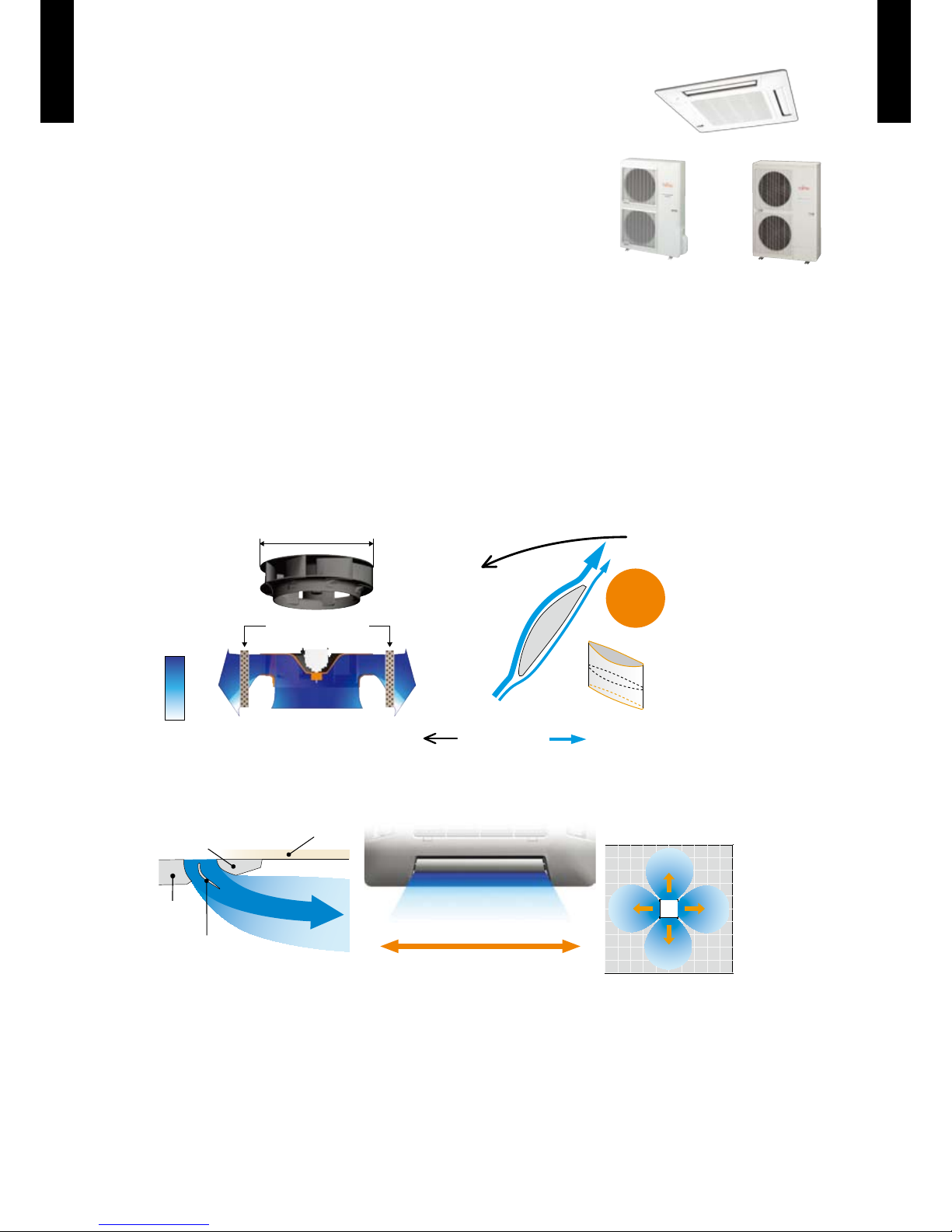
Adoption of high efficiency turbo fan
High efciency achieved by equaling the performance of the wing and air passing the heat
exchanger
Important of the flap
Making space between the ceiling, the air ows far wide and ceiling does not get dirty.
500mm
Wind
velocity
Fast
Slow
3-dimensional wing
: Spin direction : Airflow direction
No airflow
separation
Quiet
< Motor side >
Heat exchanger
Rear part
Front part
Ceiling
Round Flap
Much less temperature irregularity
happens by spreading air flow widely
Bottom view
AOA45LBTL AOA45LCTL
AOA54LCTL
Page 5

- (01 - 02) -
CASSETTE TYPE
AU
A45-54LC
CASSETTE TYPE
AU
A45-54LC
High lift drain pump
z
850mm
Ceiling panel
Simplication of drain water check
z
Drain and contamination check are possible
without removing the decoration panel.
Can be easily checked by removing the drain
cover.
Easy installation
z
Easy setting by wired
remote controller
Improvement of installation & maintenance
z
Adjustment of nut is possible after installation •
Mounting position of body can be ne adjusted after Decoration panel mounting.
Grille corner
Adjustment
can be done just taking
off the corner part
1.5
3
7 5 3 73 5
Side view
Airflow range of 2m / s
120120
Wide & powerful airflow
The wind is widely delivered by a high efciency fan and round ap.
[m]
DRAIN CAP
DRAIN COVER
Page 6

- (01 - 03) -
CASSETTE TYPE
AU
A45-54LC
CASSETTE TYPE
AU
A45-54LC
FUNCTION SETTING
Other functions
z
Performs operation matched to the number of outlets when 4 directions are unnecessary and •
outlets are blocked when the ceiling cassette is installed in a corner, etc.
Ceiling switching function
z
Also delivers air to high ceilings by selecting the mode and raising the air ow according to the
height of the ceiling.
Low ceiling (Mode 1)
4.2m
3.2m
2.7m
High ceiling (Mode 2) Standard ceiling (Standard)
Standard ...Operates at normal air ow.
Mode 1 ...Air ow becomes smaller than normal.
Mode 2 ...Air ow becomes greater than normal.
Filter sign
z
The indoor unit has sign to inform the user that it is time to clean the lter
Cooling room temperature correction
z
Heating room temperature correction
z
Auto restart
z
The units restart automatically when the current was returned even when there was a power
interruption during operation.
Room temperature sensor switching
z
Switches from room temperature judgment by room temperature sensor attached to indoor
unit body to room temperature judgment by room temperature sensor attached to wired remote
controller.
Economy operation
z
The power consumption can be reduced.
Powerful mode ...Standard
Soft mode ...Performs operation which reduces the power consumption
4-way direction 3-way direction
4-way direction mode: Set when there are 4 outlets
(shipped state).
3-way direction mode: Set when there are 3 outlets.
Page 7

- (01 - 04) -
CASSETTE TYPE
AU
A45-54LC
CASSETTE TYPE
AU
A45-54LC
WIRED REMOTE CONTROLLER2.
FEATURES
Various timer setup (ON / OFF / WEEKLY) are possible.
Equipped with weekly timer as standard function.
(2 times Start / Stop per day for a week)
When setting up a timer, operation mode and a temperature
setup can be changed.
When a failure occurs,the error code is displayed. (Maximum of 16)
Error indication.(A maximum of 16 error histories are memorizable.)
Up to 16 indoor units can be simultaneously controlled.
Economy operation are possible.
Easy installation with a slim shape with no bulge in the back.
The room temperature can be controlled by being detected the
temperature accurately with built-in thermo sensor.
Simple function setting
z
Setting of the air conditioner selection function is performed by remote controller.
High performance and compact size
z
Three functions are combined in
one unit.
Built-in timers
z
Wired
remote
controller
Weekly
timer
Setback
timer
+ +
Weekly timer Setback timer
At "Weekly timer" + "Set back timer" setup
Easy-to-understand operation
z
[Variable timer control]
The operation/display sections are zoned
according to time and operation, enabling
variable programming to match application.
Simple installation
z
Components are compatible with standard
switch boxes. Flat back construction allows
equipment to be installed wherever it is
needed.
European
switch box
JIS box
SUMOTUWETH FR SA
7
3126 9
15 18 21
SUMOTUWETH FR SA
7
3126 9
15 18 21
SUMOTUWETH FR SA
3126 9
15 18 21
Possible to set ON/OFF time to operate twice each day
of the week.
Setup scr een example
(Set to Wednes day: 8:00 to 20:00.)
Screen
after setup
Setup scr een example
(Set from Sunday to Satu rday: 12:00 to 15:00, 28 °C.)
Possible to set temperature for two time spans and
for each day of the week.
Easy-to-understand time bar display
24°C
0 3 6 9 12 15 18 21 Time
28°C
0 3 6 9 12 15 18 21 Time
28°C
24°C
0 3 6 9 12 15 18 21 Time
24°C 28°C 24°C
Timer
area
Operation
area
Page 8
- (01 - 05) -
CASSETTE TYPE
AU
A45-54LC
CASSETTE TYPE
AU
A45-54LC
FUNCTIONS
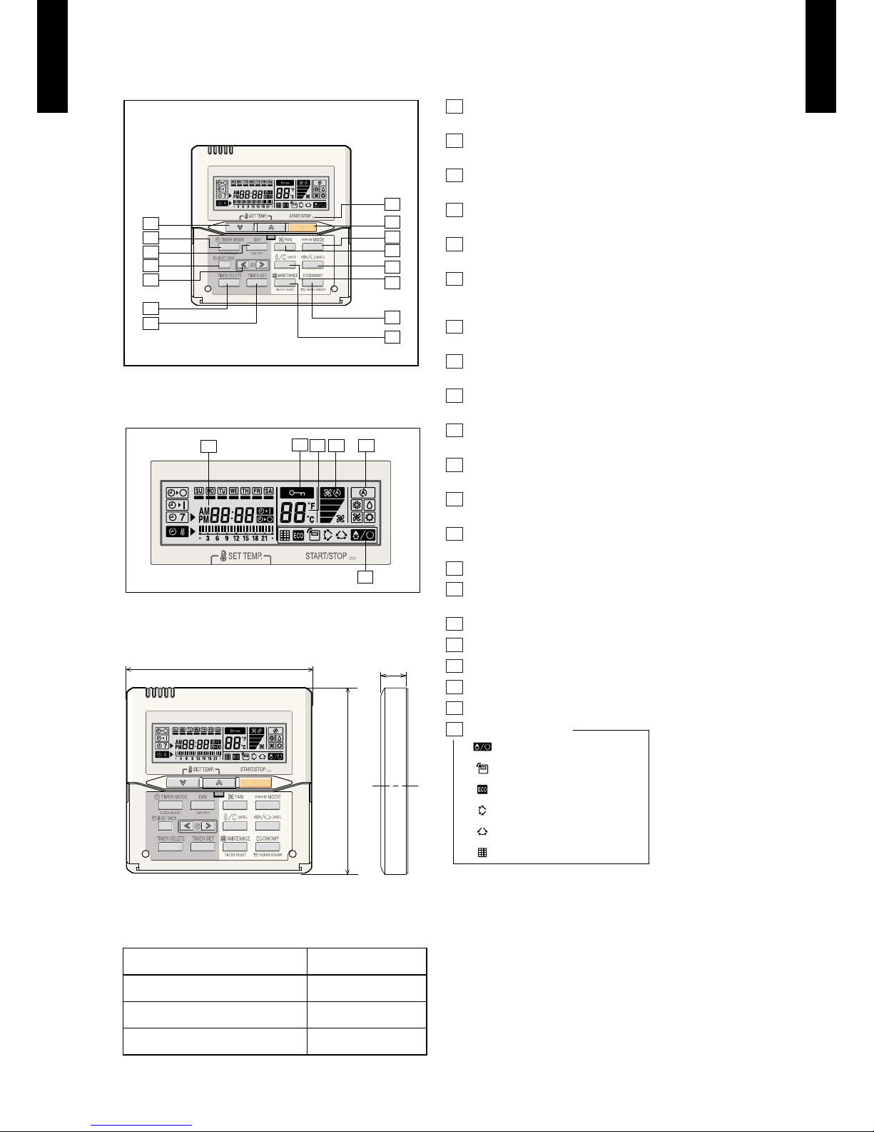
Display panel
DIMENSION
SPECIFICATION
15
11
10
9
8
2
1
3
5
14
4
12
13
6
7
17
16
18
19
20
21
120
18
120
SIZE (H x W x D mm) 120 x 120 x 18
WEIGHT ( g ) 160
CABLE LENGTH ( m ) 10
POWER ( V ) 12
1
START/STOP button
Pressed to start and stop operation.
2
SET TEMP. button
Selects the setting temperature.
3
MODE button
Selects the operating mode (AUTO, HEAT, FAN, COOL, DRY).
4
FAN button
Selects the fan speed (AUTO, QUIET, LOW, MED, HIGH).
5
ECONOMY (THERMO SENSOR) button
Turns the economy efcient mode on and off.
6
TIMER MODE (CLOCK ADJUST) button
Selects the timer mode (OFF TIM ER, ON TIMER, WEEKLY
TIMER). Set the current time.
7
DAY (DAY OFF) button
Temporarily cancels of one day timer.
8
SET BACK buttonn
Pressed to select the set back timer.
9
Set time button
Pressed to set time.
10
TIMER DELETE button
The schedule of a weekly timer is deleted.
11
TIMER SET button
Sets the date, hour, minute and on-of f time.
12
Vertical airow direction and swing button
Push for two seconds to change the swing mode.
13
Horizontal airow direction and swing button
Push for two seconds to change the swing mode.
14
FILTER RESET button
15
Operation lamp
Lights during operation and when the timer is on.
16
Timer and clock display
17
Operation mode display
18
Fan speed display
19
Operation lock display
20
Temperature display
21
Function display
Defrost display
Thermo sensor display
Economy display
Vertical swing display
Horizontal swing display
Filter display
Functions will be di fferent due to type of indoor unit.
For detail s, pleas e see operation manual.
[ Unit : mm ]
Front View
Page 9

- (01 - 06) -
CASSETTE TYPE
AU
A45-54LC
CASSETTE TYPE
AU
A45-54LC
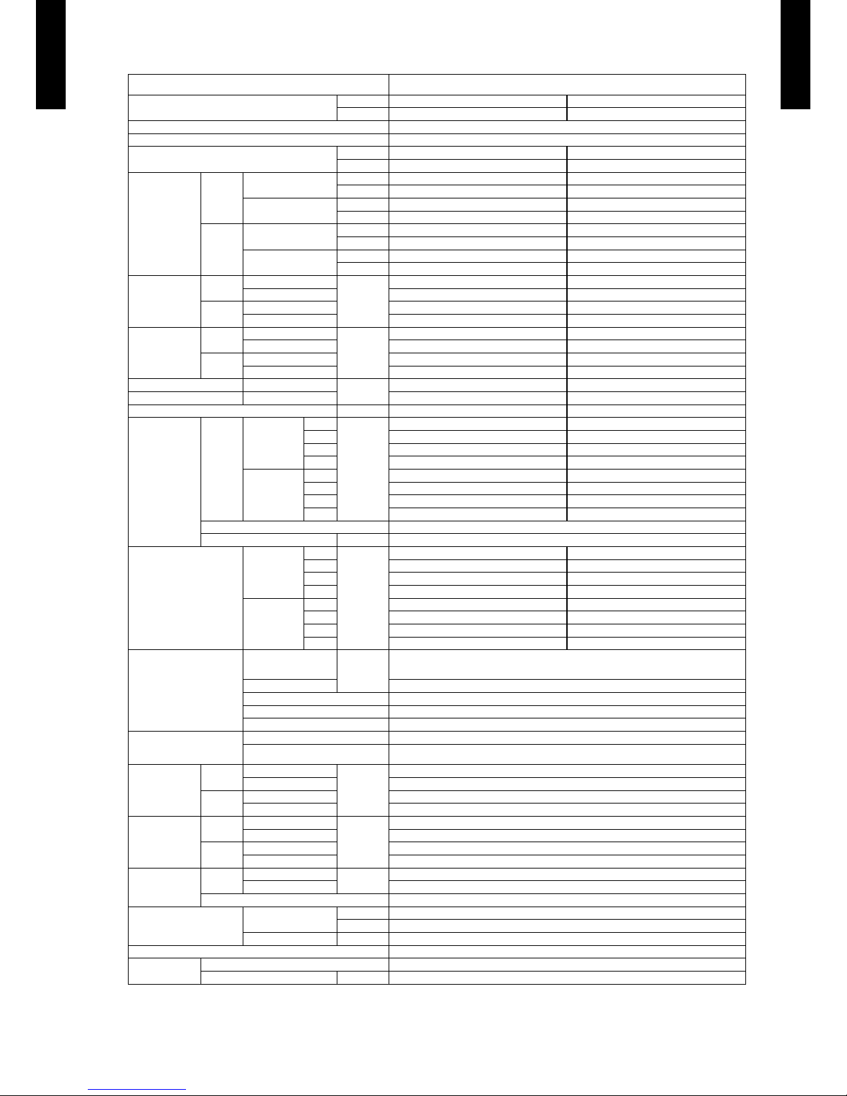
SPECIFICATIONS3.
Note :
Speci cations are base d on the fol lowing c onditi ons.
Coolin g : Indoor t emperat ure of 27 °CD B / 19 °CWB.a nd outdo or temper ature of 3 5 °CDB/ 24 °CWB.
Heating : I ndoor te mperat ure of 20 °CD B / 15 °CWB.a nd outdoo r temper ature of 7 °C DB/6 °CW B.
Pipe leng th : 7.5 m, Height di ffere nce : 0 m.(Out door uni t - Indoor u nit)
The maxi mum cur rent is the m aximum v alue when o perate d within t he operat ion range (tempera ture)
Typ e
CASSE TTE MO DEL
INVER TER HE ATPUMP
Model na me
Indoor u nit AUA45LC LU
Outdoo r unit
AOA45LBTL
Power source 230V ~ 50 Hz
Availabl e voltag e range 198-2 64V ~ 50H z
Europea n energy l abel
Cooling A
Heating A
Capacity
Cooling
Rated
kW 12.5
BTU/h 42700
Min-Max
kW 4.0-14.0
BTU/h 13700-47800
Heating
Rated
kW 14.0
BTU/h 4780 0
Min-Max
kW 4.2-16.2
BTU/h 14300-55300
Input pow er
Cooling
Rated
kW
3.89
Max 4.56
Heating
Rated 3.77
Max 4.56
Current
Cooling
Rated
A
17.0
Max 20.0
Heating
Rated 16.5
Max 20.0
EER Cooling
kW/kW
3.21
COP Heating 3.71
Moistu re remova l l/h (pin ts/h) 4.5(7.9)
Fan
Airow
rate
Cooling
High
m
3
/h
1900
Med 164 0
Low 14 60
Quiet 1250
Heating
High 19 00
Med 164 0
Low 14 60
Quiet 1250
Type × Q'ty Turbo × 1
Motor ou tput W 80
Sound pr essure l evel
Cooling
High
dB(A)
46
Med 42
Low 40
Quiet 36
Heating
High 46
Med 42
Low 40
Quiet 36
Heat excha nger t ype
Dimens ions (H × W × D)
mm
252×2021×13.3
252×2087×13.3
252×2153×13.3
Fin pitch 1.3
Rows x Sta ges 3 x 12
Pipe ty pe Copper
Fin type Aluminium
Enclos ure (Pane l)
Material Steel (HIPS)
Colour
WHITE
Approx imate co lour of M UNSEL L N 9.25/
Dimens ions
( H×W×D)
Net
Unit
mm
288×840×840
Panel 50×950×950
Gross
Unit 360×960×9 85
Panel 115×1120×100 0
Weight
Net
Unit
kg(lbs.)
27(6 0)
Panel 5. 5(12)
Gross
Unit 33( 73)
Panel 8.5 (19)
Connec tion pi pe
Size
Liquid
mm
Ø 9.52 (3/8 in .)
Gas Ø 15.88 (5/8 in .)
Method Flare
Operat ion ran ge
Cooling
°C 18 to 32
%RH 80 or les s
Heating °C 16 to 30
Remote co ntrol ler typ e Wired
Drain pi pe
Material PVC(V P25)
Size mm Outer dia meter : 32 .0 / Inner d iameter : 2 5.0
Page 10
- (01 - 07) -
CASSETTE TYPE
AU
A45-54LC
CASSETTE TYPE
AU
A45-54LC
Note :
Speci cations are base d on the fol lowing c onditi ons.
Coolin g : Indoor t emperat ure of 27 °CD B / 19 °CWB.a nd outdo or temper ature of 3 5 °CDB/ 24 °CWB.
Heating : I ndoor te mperat ure of 20 °CD B / 15 °CWB.a nd outdoo r temper ature of 7 °C DB/6 °CW B.
Pipe leng th : 5 m, Heig ht diffe rence : 0 m. (Outdoor u nit - Indo or unit)
The maxi mum cur rent is the m aximum v alue when o perate d within t he operat ion range(temper ature)
Typ e
CASSE TTE MO DEL
INVER TER HE ATPUMP
Model na me
Indoor u nit AUA45LC LU AUA54LC LU
Outdoo r unit
AOA45LC TL
AOA54LC TL
Power source 230V ~ 50 Hz
Availabl e voltag e range 198-2 64V ~ 50H z
Europea n energy l abel
Cooling A B
Heating A B
Capacity
Cooling
Rated
kW 12.5 13.3
BTU/h 42700 45400
Min-Max
kW 4.0-14.0 4.5-14.5
BTU/h 13700-47800 15400-49500
Heating
Rated
kW 14.0 16.0
BTU/h 4780 0 54600
Min-Max
kW 4.2-16.2 4.7-16.5
BTU/h 14300-55300 16000-56300
Input pow er
Cooling
Rated
kW
3.88 4.42
Max 4.70 4.94
Heating
Rated 3.77 4.69
Max 4.70 4.94
Current
Cooling
Rated
A
16.9 19 .3
Max 20.5 21.5
Heating
Rated 16.5 20.5
Max 20.5 21.5
EER Cooling
kW/kW
3.22 3.01
COP Heating 3.71 3.41
Moistu re remova l l/h (pin ts/h) 4.5 (7.9) 5.0 (8.8)
Fan
Airow
rate
Cooling
High
m
3
/h
1900 2000
Med 1640 170 0
Low 14 60 153 0
Quiet 1250 13 00
Heating
High 19 00 2000
Med 1640 170 0
Low 14 60 153 0
Quiet 1250 13 00
Type × Q'ty Turbo × 1
Motor ou tput W 80
Sound pr essure l evel
Cooling
High
dB(A)
46 47
Med 42 43
Low 40 41
Quiet 36 37
Heating
High 46 47
Med 42 43
Low 40 41
Quiet 36 37
Heat excha nger t ype
Dimens ions (H × W × D)
mm
252×2021×13.3
252×2087×13.3
252×2153×13.3
Fin pitch 1.3
Rows x Sta ges 3 x 12
Pipe ty pe Copper
Fin type Aluminium
Enclos ure (Pane l)
Material Steel (HIPS)
Colour
WHITE
Approx imate co lour of M UNSEL L N 9.25/
Dimens ions
( H×W×D)
Net
Unit
mm
288×840×840
Panel 50×950×950
Gross
Unit 360×960×9 85
Panel 115×1120×100 0
Weight
Net
Unit
kg(lbs.)
27(6 0)
Panel 5. 5(12)
Gross
Unit 33( 73)
Panel 8.5 (19)
Connec tion pi pe
Size
Liquid
mm
φ9.52 (3/ 8 in.)
Gas φ15.88 (5/8 i n.)
Method Flare
Operat ion ran ge
Cooling
°C 18 to 32
%RH 80 or les s
Heating °C 16 to 30
Remote co ntrol ler typ e Wired
Drain pi pe
Material PVC(V P25)
Size mm Outer dia meter : 32 .0 / Inner d iameter : 2 5.0
Page 11

- (01 - 08) -
CASSETTE TYPE
AU
A45-54LC
CASSETTE TYPE
AU
A45-54LC
DIMENSIONS4.
MODEL : AUA45LC, AUA54LC
Ceiling opening and hanging bolt pitch
z
(Unit : mm)
Refrigerant piping and drain piping positions
z
Airow split-ow duct and fresh air inlet positions
z
288
298
40
10
140 - 145
50 - 100
950 (Panel frame)
54 - 02 54 - 02
50
80
130
130
130
200
840 (Body frame)
795 (Hanging bolt pitch)
699 (Hanging bolt pitch)
860 - 910 (Ceiling opening)
950 (Panel frame)
54 - 02 54 - 02
840 (Body frame)
860 - 910 (Ceiling opening)
60278358
140
180
200
Drain pipe
(Connect the attached drain hose)
88
70
2.5 hole
2.5 hole
250
352
100
8383
90
100
581 581
Airflow split-flow duct connecting port
Airflow split-flow duct connecting port
Airflow split-flow duct connecting port
Fresh air inlet position
Fresh air inlet position
Drain pipe
Refrigerant pipe
Detailed diagram of branched duct connecting port
(4 sides)
Knockout hole pitch
Cut out
Cut out
Airflow split-flow duct connecting port
10
4
Page 12

- (01 - 09) -
CASSETTE TYPE
AU
A45-54LC
CASSETTE TYPE
AU
A45-54LC
INSTALLATION PLACE
(Unit : mm)
3-way directions setting
z
To set “3-way directions”, the air outlet shutter plate (UTR-YDZC) sold separately must be installed
and “outlet-direction” switched to “3-way” by remote controller.
1,500
or more
1,000 or more
1,800 or more
Obstruction
3,000 or more
Strong and durable ceiling
Floor
Ceiling mode “Low” : 2.7 m
Ceiling mode “Standard” : 3.2 m
Ceiling mode “High” : 4.2 m
100 or more
Page 13

- (01 - 10) -
CASSETTE TYPE
AU
A45-54LC
CASSETTE TYPE
AU
A45-54LC
WIRING DIAGRAMS5.
MODEL : AUA45LC, AUA54LC
Page 14
- (01 - 11) -
CASSETTE TYPE
AU
A45-54LC
CASSETTE TYPE
AU
A45-54LC
CAPACITY TABLE6.
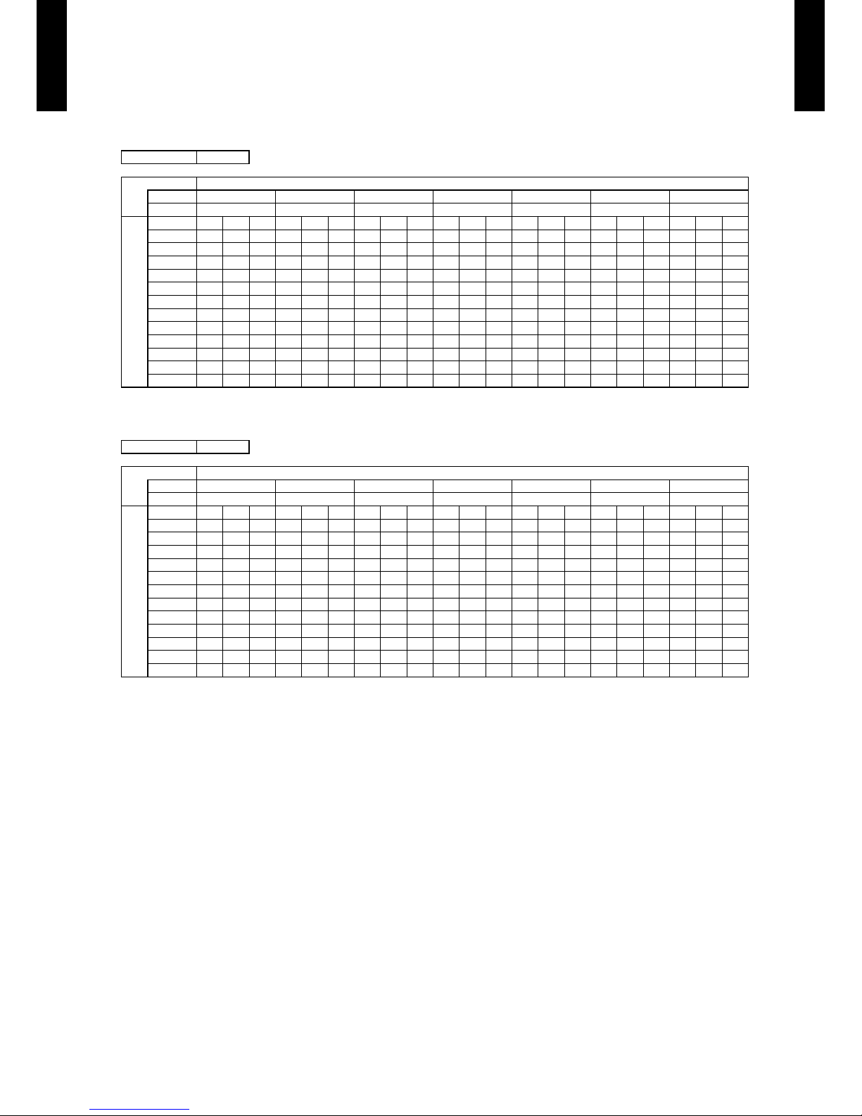
COOLING CAPACITY6-1.
This table is created using the maximum capacity.
MODEL : AUA45LC / AOA45LB
MODEL : AUA45LC / AOA45LC
AFR : Air ow rate (m3/min)
TC : Total capaci ty (kW )
SHC : Sens ible Hea t capaci ty (kW )
IP : Input Pow er (kW)
AFR 31.7
Indoor t empera ture
°CDB 18 21 23 25 27 29 32
°CWB 12 15 16 18 19 21 23
Outdoo r temper ature
°CDB TC SHC IP TC SHC IP TC SHC IP TC SH C IP TC SHC IP TC SHC IP TC SHC IP
-15 11.00 8 .83 1.99 12. 26 8. 88 2.03 12.6 8 9.65 2.04 13.51 9.68 2.06 13. 93 10.46 2 .07 14.76 10.42 2.0 9 15.60 11.10 2.11
-10 10.95 8.78 1.99 12.19 8.8 3 2.03 12.61 9.60 2.04 13.4 4 9.6 3 2.06 13.8 6 10.40 2.07 14.69 10.36 2.09 15 .52 11.04 2.11
0 10.88 8.51 2.00 12.11 8.5 6 2.04 12.53 9.31 2.05 13. 35 9.3 4 2.07 13.77 10.0 8 2.0 8 14.59 10.04 2.10 15.42 10.70 2.1 2
5 10.83 8.61 2.05 12.0 6 8.6 6 2.08 12.47 9.41 2.09 13. 30 9. 44 2.11 13.71 10.20 2 .12 14.53 10.16 2 .15 15.3 5 10.82 2.17
10 10.81 8 .73 2.1 2 12.05 8.79 2.16 12. 46 9. 55 2.17 13.28 9.5 8 2.19 13.69 10.35 2.20 14.51 10.31 2. 22 15. 33 10.98 2. 25
15 10.75 8.71 2.23 11.97 8.76 2.26 12.38 9. 53 2.27 13.2 0 9.5 6 2.29 13.61 10.32 2.31 14.42 10.28 2. 33 15. 24 10.95 2. 35
20 11.01 8.69 2.74 12.26 8.74 2.78 12.6 8 9.5 0 2.79 13.51 9.53 2.82 13. 93 10.29 2. 84 14.7 7 10.25 2. 87 15.6 0 10.92 2.8 9
25 11.09 8.8 0 3.18 12.35 8.85 3.23 12 .77 9. 62 3.25 13.6 2 9.65 3.28 14.04 10.42 3.30 14.88 10.38 3. 33 15.7 2 11.06 3.36
30 11.36 8.84 4.30 12.66 8. 89 4.36 13.0 9 9.67 4.38 13.95 9.70 4.43 14. 38 10.47 4. 45 15. 24 10.43 4. 50 16.11 11.11 4.5 4
35 11.06 8.98 4.29 12.32 9. 03 4.35 12.74 9.82 4.38 13.58 9. 85 4.42 14.0 0 10.64 4.4 4 14.8 4 10.60 4.4 9 15.6 8 11.29 4.5 3
40 8.64 7.7 1 3.59 9.63 7.75 3.65 9.96 8.43 3.67 10. 61 8.46 3.71 10.9 4 9 .13 3.72 11.60 9.10 3.76 12. 26 9.6 9 3.80
46 5.97 6.37 2.71 6.65 6.41 2.76 6.88 6.97 2.77 7. 33 6.99 2.80 7.56 7.55 2.81 8.01 7.52 2.84 8.47 8.01 2.87
AFR 31.7
Indoor t empera ture
°CDB 18 21 23 25 27 29 32
°CWB 12 15 16 18 19 21 23
Outdoo r temper ature
°CDB TC SHC IP TC SHC IP TC SHC IP TC SH C IP TC SHC IP TC SHC IP TC SHC IP
-15 11.34 8.71 2.56 12.6 3 8.76 2.6 0 13.06 9.52 2.62 13. 92 9. 55 2.64 14.3 5 10.32 2.6 6 15. 21 10.28 2.6 8 16.07 10.9 5 2.71
-10 11.44 8.70 2.46 12.74 8.75 2.50 13.17 9.51 2.51 14.0 4 9.5 5 2.54 14.48 10.31 2.55 15.35 10.27 2. 58 16. 21 10.94 2.6 0
0 11.55 8.77 2.23 12. 87 8.8 3 2.26 13.31 9.60 2.28 14.18 9.6 3 2.30 14.62 10.4 0 2. 31 15.50 10.35 2.33 16.38 11.03 2. 36
5 11.37 8.78 2.30 12.6 7 8.8 4 2.34 13.10 9.61 2.35 13. 96 9. 64 2.37 14.4 0 10.41 2.39 15.2 6 10.37 2. 41 16.12 11.04 2.43
10 11.11 8 .78 2.49 12.37 8.83 2.53 12.79 9. 60 2.54 13.6 4 9.6 3 2.57 14.06 10.40 2.58 14.90 10.36 2 .61 15.74 11.04 2.6 3
15 10.84 8 .68 2.69 12. 07 8 .74 2.73 12.48 9.50 2.74 13.31 9. 53 2.77 13.72 10.2 9 2.78 14.54 10.25 2.81 15.37 10.92 2. 84
20 11.22 8.69 3.15 12.49 8.74 3.20 12.9 2 9.5 0 3.22 13.77 9.53 3.25 14. 20 10.29 3. 27 15.0 5 10.25 3. 30 15.9 0 10.92 3.3 3
25 11.10 8.78 3.36 12.36 8 .83 3.41 12.79 9.6 0 3.43 13.63 9.63 3.46 14.05 10.40 3. 48 14.8 9 10.36 3.51 15 .74 11.03 3.5 5
30 11.34 8.84 4.27 12.63 8. 89 4.34 13.0 6 9.67 4.36 13.92 9.70 4.41 14.3 5 10.48 4.4 3 15. 21 10.43 4.4 3 16.07 11.11 4.43
35 11.06 8.82 4.53 12.32 8 .87 4.60 12.74 9.64 4.62 13.58 9.68 4.67 14.0 0 10.45 4.6 9 14.8 4 10.41 4.6 9 15.6 8 11.09 4.6 9
40 8.79 7.66 3.92 9.79 7.83 3.98 10.13 8.52 4.00 10. 80 8. 54 4.04 11.13 9.23 4.06 11.80 9.1 9 4.0 6 12.47 9.79 4.06
46 6.69 6.63 3.24 7.45 6.87 3.29 7.7 1 7.47 3.31 8.22 7.49 3.34 8.47 8.09 3.36 8.98 8.06 3.36 9.49 8.58 3.36
Page 15

- (01 - 12) -
CASSETTE TYPE
AU
A45-54LC
CASSETTE TYPE
AU
A45-54LC
This table is created using the maximum capacity.
MODEL : AUA54LC
AFR : Air ow rate (m3/min)
TC : Total capaci ty (kW )
SHC : Sens ible Hea t capaci ty (kW )
IP : Input Pow er (kW)
AFR 33.3
Indoor t empera ture
°CDB 18 21 23 25 27 29 32
°CWB 12 15 16 18 19 21 23
Outdoo r temper ature
°CDB TC SHC IP TC SHC IP TC SHC IP TC SH C IP TC SHC IP TC SHC IP TC SHC IP
-15 11.73 9.03 2.69 13.07 9.08 2.73 13.52 9 .87 2.75 14.41 9.9 0 2.78 14.85 10.69 2.79 15.74 10.65 2. 82 16.6 4 11.35 2. 85
-10 11.72 9 .04 2.59 13. 06 9.10 2.63 13.50 9.89 2.64 14.39 9. 92 2.67 14.8 4 10.71 2.6 8 15.73 10.67 2.71 16.62 11.37 2.73
0 11.84 9 .12 2. 33 13.19 9 .17 2.36 13.64 9.97 2.37 14.5 4 10.01 2. 40 14.9 9 10.81 2 .41 15.8 9 10.76 2.4 3 16.78 11.46 2.46
5 11.60 8 .96 2.42 12. 92 9. 02 2.46 13.37 9.80 2.47 14.25 9. 83 2.50 14.6 9 10.62 2 .51 15.5 7 10.58 2.5 4 16.45 11.27 2.56
10 11.44 8. 90 2.54 12.74 8.95 2.58 13.18 9.73 2.59 14.04 9.76 2.62 14.48 10.54 2.63 15. 35 10.50 2. 66 16.2 2 11.18 2.6 8
15 11.22 8. 99 2.80 12.5 0 9.0 4 2.85 12.92 9.83 2.86 13.77 9.8 6 2.89 14.2 0 10.65 2.91 15.05 10.61 2.93 15. 90 11.30 2. 96
20 12.0 6 9.5 5 3.73 13.43 9.61 3.79 13. 89 10.45 3.81 14. 81 10.48 3.8 5 15.2 6 11.32 3.8 7 16 .18 11.27 3.9 0 17.10 12.01 3. 94
25 11.82 9 .10 4.31 13.17 9 .15 4. 38 13. 62 9.9 5 4.40 14.52 9.98 4.45 14.97 10.78 4.47 15.8 6 10.73 4. 51 16.76 11.43 4.56
30 11.62 8.98 4.52 12.95 9.0 4 4.59 13.3 9 9.8 2 4.61 14.27 9.86 4.66 14.71 10.64 4.6 8 15.5 9 10.60 4.6 8 16.48 11.29 4.68
35 11.46 8.89 4.75 12.76 8. 95 4.82 13.2 0 9.73 4.8 5 14.07 9.76 4.90 14. 50 10.54 4 .92 15. 37 10.50 4. 92 16. 24 11.18 4.9 2
40 9.11 8.03 3.94 10.15 8.21 4.00 10.49 8. 93 4.02 11.18 8.9 6 4.06 11.53 9.67 4.08 12. 22 9.6 3 4.08 12.91 10.2 6 4.08
46 6.94 6.91 3.26 7.73 7.16 3.31 7.99 7.78 3.33 8.52 7.81 3.36 8.78 8.43 3.38 9.31 8.40 3.38 9.83 8.94 3.38
Page 16
- (01 - 13) -
CASSETTE TYPE
AU
A45-54LC
CASSETTE TYPE
AU
A45-54LC
HEATING CAPACITY6-2.
This table is created using the maximum capacity.
MODEL : AUA45LC / AOA45LB
MODEL : AUA45LC / AOA45LC
AFR : Air o w rate (m3/min)
TC : Total capaci ty (kW)
IP : Input Pow er (kW)
AFR 31.7
Indoor temperature
°CDB 16 18 20 22 24
Outdoo r temper ature
°CDB °CWB TC IP TC IP TC IP TC IP TC IP
-15 -16 11.43 4.49 11.16 4.58 10.89 4.67 10.62 4.77 10.35 4.86
-10 -11 12.38 4.49 12.08 4.58 11.79 4.67 11.49 4.77 11. 20 4.86
-5 -7 13 .18 4.48 12.87 4.57 12.55 4.67 12. 24 4.76 11.93 4.85
0 -2 14.10 4.48 13.77 4.58 13.4 3 4.67 13.09 4.76 12.76 4.86
5 3 16.02 4.49 15.64 4.58 15.25 4.67 14.87 4.77 14.49 4.86
7 6 17.01 4.49 16.61 4.58 16.20 4.67 15.80 4.77 15. 39 4.86
10 8 17.19 4.35 16.78 4.44 16. 37 4.53 15.96 4.62 15. 55 4.71
15 10 1 7.3 2 4.10 16.91 4.19 16.50 4.28 16.09 4.36 15.67 4.43
20 15 17. 46 3.06 17. 05 3.12 16.63 3.19 16.22 3.25 15.80 3.30
24 18 17. 51 3.00 1 7.10 3.0 6 16.68 3.12 16.26 3.19 15.84 3.24
AFR 31.7
Indoor temperature
°CDB 16 18 20 22 24
Outdoo r temper ature
°CDB °CWB TC IP TC IP TC IP TC IP TC IP
-15 -16 10.90 4.14 10.6 4 4. 22 10.38 4.31 10.12 4.40 9.86 4.48
-10 -11 11.86 4.29 11.57 4.38 11. 29 4.47 11.01 4.56 10.73 4.65
-5 -7 12.96 4.25 12. 65 4.3 4 12.34 4.43 12.03 4.43 11.73 4.43
0 -2 14.01 4.25 13.68 4.34 13.35 4.43 13.01 4.43 12.68 4.43
5 3 15.51 4.25 15.1 4 4.34 14.77 4.43 14.40 4.43 14.03 4.43
7 6 17.01 4.25 16.61 4.3 4 16.20 4.43 15.80 4.43 15.39 4.43
10 8 17.29 4.25 16.88 4.34 16.46 4.43 16.05 4.43 15.64 4.43
15 10 16.80 3.80 16 .40 3.88 16.00 3.96 15.60 3.96 15.20 3.96
20 15 16.27 3.80 15.88 3.88 15.49 3.96 15.10 3.96 14.72 3.96
24 18 16.79 3.26 16.39 3.33 15.99 3.40 15.60 3.40 15.20 3.40
Page 17

- (01 - 14) -
CASSETTE TYPE
AU
A45-54LC
CASSETTE TYPE
AU
A45-54LC
This table is created using the maximum capacity.
MODEL : AUA54LC
AFR : Air o w rate (m3/min)
TC : Total capaci ty (kW)
IP : Input Pow er (kW)
AFR 33.3
Indoor temperature
°CDB 16 18 20 22 24
Outdoo r temper ature
°CDB °CWB TC IP TC IP TC IP TC IP TC IP
-15 -16 11.00 4.16 10.73 4.24 10.47 4.33 10. 21 4.42 9.95 4.50
-10 -11 12.08 4.31 11.79 4.40 11.50 4.49 11.22 4.58 10.93 4.67
-5 -7 13.30 4.49 12.99 4.59 12.67 4.68 12.35 4.68 12.04 4.68
0 -2 14.44 4.49 14.10 4.59 13.75 4.68 13.41 4.68 13.07 4.68
5 3 16.01 4.49 15.62 4.59 15.24 4.68 14.86 4.68 14.48 4.68
7 6 17. 33 4.49 16. 91 4.59 16.50 4.68 16.09 4.68 15.68 4.68
10 8 17.61 4.49 17.19 4.59 16.77 4.68 16.35 4.68 15.93 4.68
15 10 16.97 3.82 16.57 3.90 16.16 3.98 15 .76 3.98 15.35 3.98
20 15 16.43 3.37 16.04 3.44 15.65 3.51 15.25 3.51 14.86 3.51
24 18 16.96 3.37 16. 56 3.44 16.15 3.51 15 .75 3.51 15.35 3.51
Page 18

- (01 - 15) -
CASSETTE TYPE
AU
A45-54LC
CASSETTE TYPE
AU
A45-54LC
FAN PERFORMANCE7.
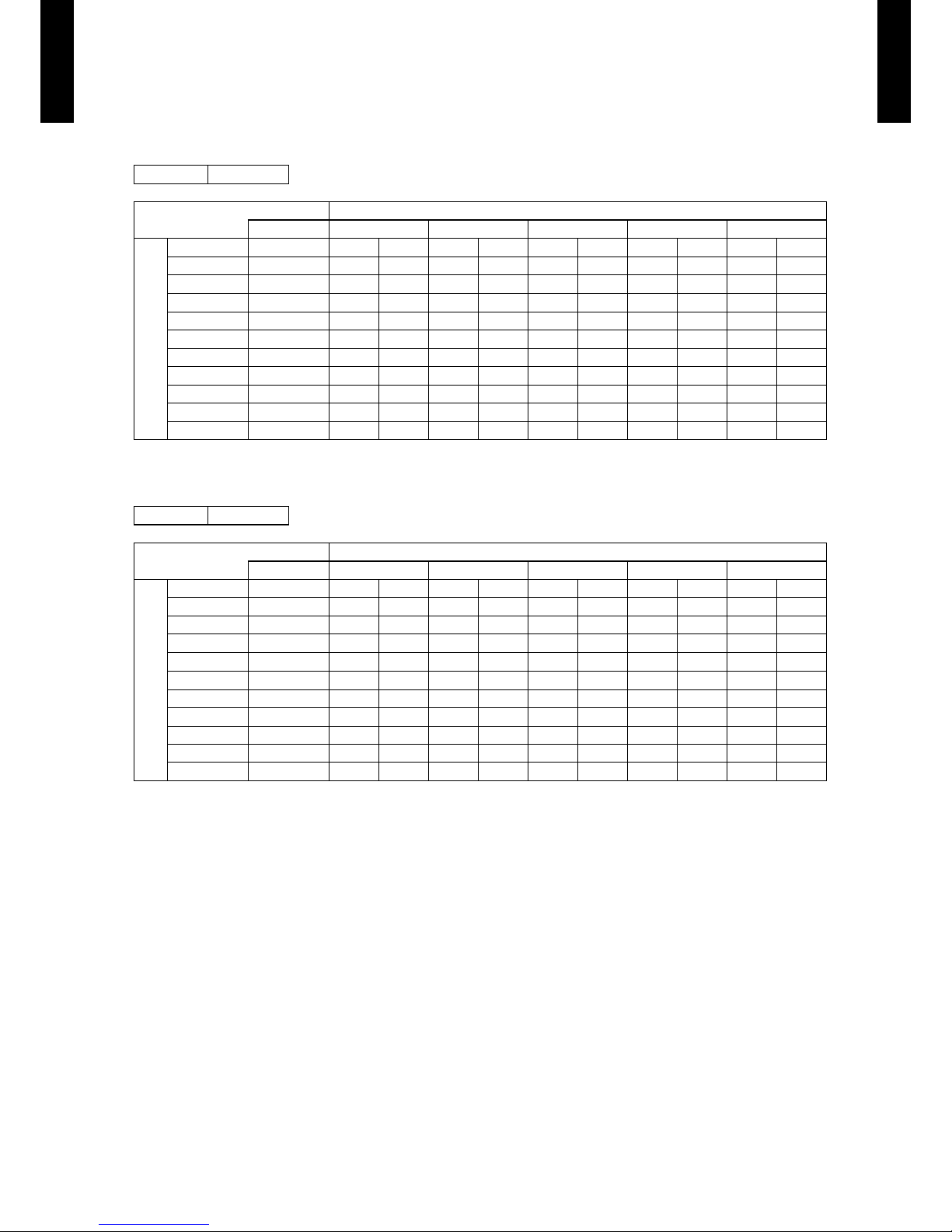
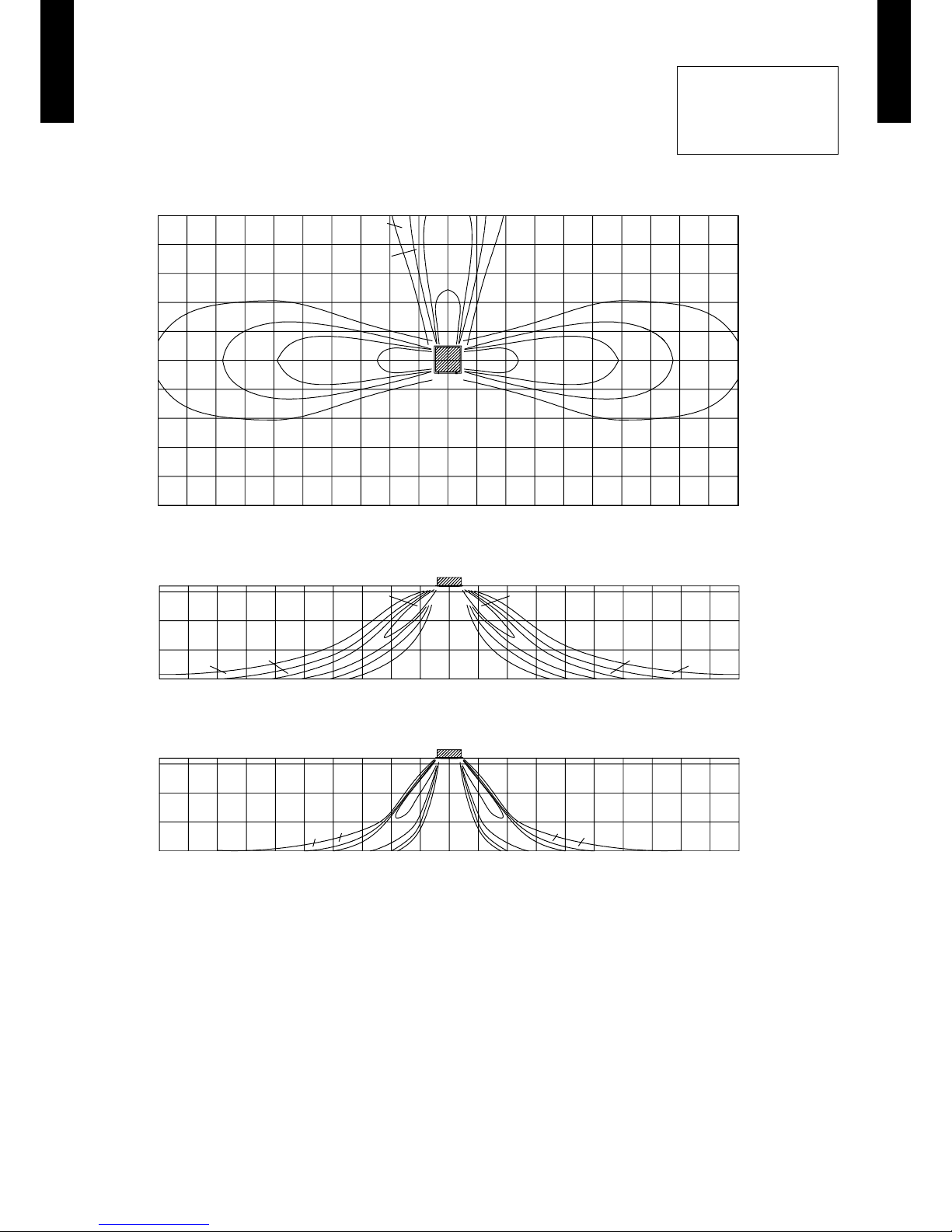
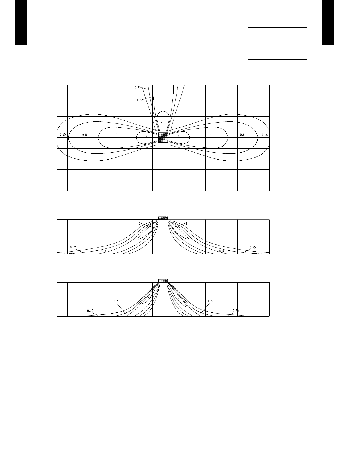
AIR VELOCITY DISTRIBUTION7-1.
STANDARD MODE7-1-1.
MODEL : AUA45LC
4-way air outlet
z
Note:
Condition
Fan speed : High
Operation mode : FAN
Ceiling mode : Standard
5
4
3
2
1
0
1
2
3
4
5
Unit : m/s(m)
(m)
TOP VIEW
VERTICA L LOUVER
: Upward
3.2
2
1
0
Unit : m/s(m)
(m)
SIDE VIE W
VERTICA L LOUVER
: Upward
3.2
2
1
0
Unit : m/s(m)
(m)
SIDE VIE W
VERTICA L LOUVER
: D ownward
10 9 8 7 6 5 4 3 2 1 0 1 2 3 4 5 6 7 8 9 10
10 9 8 7 6 5 4 3 2 1 0 1 2 3 4 5 6 7 8 9 10
10 9 8 7 6 5 4 3 2 1 0 1 2 3 4 5 6 7 8 9 10
0.25 0.25
11
0.5 0.5
2 2
0.25 0.25
1 1
0.5 0.5
2 2
0.25
0.25
0.5
0.5
1
1
10.5 0.51
2
2 2
2
Page 19
- (01 - 16) -
CASSETTE TYPE
AU
A45-54LC
CASSETTE TYPE
AU
A45-54LC
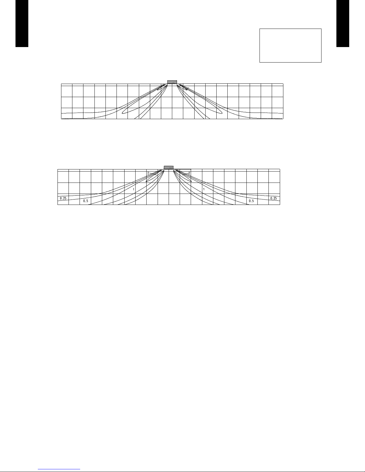
3-way air outlet
z
Note:
Condition
Fan speed : High
Operation mode : FAN
Ceiling mode : Standard
5
4
3
2
1
0
1
2
3
4
5
Unit : m/s(m)
(m)
TOP VIEW
VERTICA L LOUVER
: Upward
3.2
2
1
0
Unit : m/s(m)
(m)
SIDE VIE W
VERTICA L LOUVER
: Upward
3.2
2
1
0
Unit : m/s(m)
(m)
SIDE VIE W
VERTICA L LOUVER
: D ownward
10 9 8 7 6 5 4 3 2 1 0 1 2 3 4 5 6 7 8 9 10
10 9 8 7 6 5 4 3 2 1 0 1 2 3 4 5 6 7 8 9 10
10 9 8 7 6 5 4 3 2 1 0 1 2 3 4 5 6 7 8 9 10
0.25
1
0.5
0.25
0.5
2
1
2
0.25
1 1
0.5
0.25
0.5
2 2
0.25
0.25
1
1
0.5
0.5
2
2
0.251 0.52
Page 20

- (01 - 17) -
CASSETTE TYPE
AU
A45-54LC
CASSETTE TYPE
AU
A45-54LC
MODEL : AUA54LC
4-way air outlet
z
Note:
Condition
Fan speed : High
Operation mode : FAN
Ceiling mode : Standard
3.2
2
1
0
Unit : m/s(m)
(m)
SIDE VIE W
VERTICA L FLAP
: D ownward
10 9 8 7 6 5 4 3 2 1 0 1 2 3 4 5 6 7 8 9 10
3.2
2
1
0
Unit : m/s(m)
(m)
SIDE VIE W
VERTICA L FLAP
: Upward
10 9 8 7 6 5 4 3 2 1 0 1 2 3 4 5 6 7 8 9 10
5
4
3
2
1
0
1
2
3
4
5
Unit : m/s(m)
(m)
TOP VIEW
VERTICA L FLAP
: Upward
10 9 8 7 6 5 4 3 2 1 0 1 2 3 4 5 6 7 8 9 10
Page 21
- (01 - 18) -
CASSETTE TYPE
AU
A45-54LC
CASSETTE TYPE
AU
A45-54LC
3-way air outlet
z
Note:
Condition
Fan speed : High
Operation mode : FAN
Ceiling mode : Standard
3.2
2
1
0
Unit : m/s(m)
(m)
SIDE VIE W
VERTICA L FLAP
: D ownward
10 9 8 7 6 5 4 3 2 1 0 1 2 3 4 5 6 7 8 9 10
3.2
2
1
0
Unit : m/s(m)
(m)
SIDE VIE W
VERTICA L FLAP
: Upward
10 9 8 7 6 5 4 3 2 1 0 1 2 3 4 5 6 7 8 9 10
5
4
3
2
1
0
1
2
3
4
5
Unit : m/s(m)
(m)
TOP VIEW
VERTICA L FLAP
: Upward
10 9 8 7 6 5 4 3 2 1 0 1 2 3 4 5 6 7 8 9 10
Page 22
- (01 - 19) -
CASSETTE TYPE
AU
A45-54LC
CASSETTE TYPE
AU
A45-54LC
SPECIAL UPWARD MODE7-1-2.
MODEL : AUA45LC
4-way air outlet
z
MODEL : AUA54LC
4-way air outlet
z
Note:
Condition
Fan speed : High
Operation mode : FAN
Ceiling mode : Standard
10 9 8 7 6 5 4 3 2 1 0 1 2 3 4 5 6 7 8 9 10
(m)
SIDE VIE W
VERTICA L LOUVER
: Speci al upward
Unit : m/s(m)
3.2
2
1
0
0.25
1
0.5
2
10 9 8 7 6 5 4 3 2 1 0 1 2 3 4 5 6 7 8 9 10
(m)
SIDE VIE W
VERTICA L FLAP
: Speci al upward
Unit : m/s(m)
3.2
2
1
0
Page 23

- (01 - 20) -
CASSETTE TYPE
AU
A45-54LC
CASSETTE TYPE
AU
A45-54LC
AIR FLOW7-2.
4-WAY OUTLET7-2-1.
MODEL : AUA45LC
Cooling / Heating
z
MODEL : AUA54LC
Cooling / Heating
z
Fan speed
Number of
rotations
(r.p.m.)
Air ow
HIGH 690
m
3
/h 1900
l/s 528
CFM 1118
MED 610
m
3
/h 1640
l/s 456
CFM 965
LOW 550
m
3
/h 1460
l/s 406
CFM 859
QUIET 470
m
3
/h 1250
l/s 347
CFM 736
Fan speed
Number of
rotations
(r.p.m.)
Air ow
HIGH 720
m3/h
2000
l/s
556
CFM
1177
MED 630
m3/h
1700
l/s
472
CFM
1000
LOW 570
m3/h
1530
l/s
425
CFM
900
QUIET 480
m3/h
1300
l/s
361
CFM
765
Page 24
- (01 - 21) -
CASSETTE TYPE
AU
A45-54LC
CASSETTE TYPE
AU
A45-54LC
3-WAY OUTLET7-2-2.
MODEL : AUA45LC
Cooling / Heating
z
MODEL : AUA54LC
Cooling / Heating
z
*Air ow can be changed according to the direction in which the outlet is blocked.
Fan speed
Number of
rotations
(r.p.m.)
Air ow
HIGH 720
m
3
/h 1690
l/s 469
CFM 995
MED 640
m
3
/h 1490
l/s 414
CFM 877
LOW 580
m
3
/h 1340
l/s 372
CFM 789
QUIET 500
m
3
/h 114 0
l/s 317
CFM 671
Fan speed
Number of
rotations
(r.p.m.)
Air ow
HIGH 740
m
3
/h 1740
l/s 483
CFM 1024
MED 650
m
3
/h 1520
l/s 422
CFM 895
LOW 590
m
3
/h 1360
l/s 378
CFM 800
QUIET 500
m
3
/h 1140
l/s 317
CFM 671
Page 25

- (01 - 22) -
CASSETTE TYPE
AU
A45-54LC
CASSETTE TYPE
AU
A45-54LC
FRESH AIR7-3.
MODEL : AUA45LC, AUA54LC
Installation
z
250 mm
185 mm
2.5 mm hole4
70 mm
62 mm
62 mm
Refrigerant pipe
Fresh air inlet position(A)
Fresh air inlet position
View(A)
Drain pipe
Duct frange *2
Flexible duct *2
Fan *2
Flexible duct *2
Insulation *1
*1 : In case of fresh air intake, please remove the insulation.
*2 : Locally procured parts
Fresh air Inlet position
Duct
(Inside Dia. ø70mm)
Static pressure required
to take in fresh air
Duct Fan
98
49
0
10
8
6
4
2
0
0 0.1 0.2 0. 3 0.4 0.5 0.6 0.7
Air ow (m3/min)
Duct static pressure (Pa)
Duct static pressure (mmAq)
Page 26

- (01 - 23) -
CASSETTE TYPE
AU
A45-54LC
CASSETTE TYPE
AU
A45-54LC
DUCT CONNECTION7-4.
Outlet air
z
L
Duct
(Inside size. 350mm×100mm)
Duct static pressure (mmAq)
L=10m
L=5m
L=1m
Fan Speed
Quiet 2-way
Fan Speed
Quiet 1-way
Fan Speed
High 1-way
Fan Speed
High 2-way
98
49
0
10
9
8
7
6
5
4
3
2
1
0
0 2 4 6 8 10 12 14
Air ow (m3/min)
Duct static pressure (Pa)
L=10m
L=5m
L=1m
Fan Speed
Quiet 2-way
Fan Speed
Quiet 1-way
Fan Speed High
1-way
Fan Speed
High 2-way
98
49
0
10
9
8
7
6
5
4
3
2
1
0
0 120 240 360 480 600 720 8 40
AUA54LC
Air ow (m
3
/h)
Duct static pressure (Pa)
Duct static pressure (mmAq)
AUA45LC
Page 27

- (01 - 24) -
CASSETTE TYPE
AU
A45-54LC
CASSETTE TYPE
AU
A45-54LC
PRECAUTIONS WHILE CONNECTING AIR OUTLET DUCT
z
Connect the air outlet duct at up to two locations among the four duct
connection locations. (Do not connect ducts at three or more locations.)
z
Blow-off pattern when a branch duct is installed
Bi-directional branching, main unit bi-directional branching
z
Once the location where the duct is to be connected is decided,
always be sure to close the outlets in the same direction.
A
B
C
D
Close Close
Branch
Branch
Close
Close
Branch
Branch
DUCT (Locally procured parts)
Close the outlet here.
* Use only af ter closing the outlet of the cassette on the
side on which the duct is used, using the “Air outlet
shutter plate (UTR-YDZC)”.
Page 28

- (01 - 25) -
CASSETTE TYPE
AU
A45-54LC
CASSETTE TYPE
AU
A45-54LC
OPERATION NOISE8.
NOISE LEVEL CURVE8-1.
MODEL : AUA45LC
Condition
Ceiling mode : Standard
Air outlet : 4-way air outlet
MODEL : AUA54LC
Condition
Ceiling mode : Standard
Air outlet : 4-way air outlet
QUIET
HIGH
Heating
z
Octave ba nd soun d pressu re level, d B:(0dB= 0.00 02µba r)
Octave ba nd center frequ ency,Hz
80
70
60
50
40
30
20
10
0
63 125 250 500 1,000 2,00 0 4,00 0 8,000
NC-65
NC-60
NC-55
NC-50
NC-45
NC-40
NC-35
NC-30
NC-25
NC-20
NC -15
QUIET
HIGH
Cooling
z
Octave ba nd soun d pressu re level, d B:(0dB= 0.00 02µba r)
Octave ba nd center frequ ency,Hz
80
70
60
50
40
30
20
10
0
63 125 250 500 1,000 2,00 0 4,00 0 8,000
NC-65
NC-60
NC-55
NC-50
NC-45
NC-40
NC-35
NC-30
NC-25
NC-20
NC -15
HIGH
QUIET
Heating
z
Octave ba nd soun d pressu re level, d B:(0dB= 0.00 02µba r)
Octave ba nd center frequ ency,Hz
80
70
60
50
40
30
20
10
0
63 125 250 500 1,000 2,00 0 4,00 0 8,000
NC-65
NC-60
NC-55
NC-50
NC-45
NC-40
NC-35
NC-30
NC-25
NC-20
NC -15
HIGH
QUIET
Cooling
z
Octave ba nd soun d pressu re level, d B:(0dB= 0.00 02µba r)
Octave ba nd center frequ ency,Hz
80
70
60
50
40
30
20
10
0
63 125 250 500 1,000 2,00 0 4,00 0 8,000
NC-65
NC-60
NC-55
NC-50
NC-45
NC-40
NC-35
NC-30
NC-25
NC-20
NC -15
Page 29

- (01 - 26) -
CASSETTE TYPE
AU
A45-54LC
CASSETTE TYPE
AU
A45-54LC
SOUND LEVEL CHECK POINT8-2.
Microphone
Microphone
CENTER
1.5m
Page 30

- (01 - 27) -
CASSETTE TYPE
AU
A45-54LC
CASSETTE TYPE
AU
A45-54LC
ELECTRIC CHARACTERISTICS9.
Model name
AUA45LC
AUA54LC
Power supply
Voltage V 230 ~
Frequency Hz 50
Max. operating current (Indoor unit) A 1.2
Wiring spec. (Indoor unit to
outdoor unit)
Connection cable mm
2
1.5 - 2.5
Limited wiring length m 50
Page 31

- (01 - 28) -
CASSETTE TYPE
AU
A45-54LC
CASSETTE TYPE
AU
A45-54LC
SAFETY DEVICES10.
Protection form
Model
AUA45LC
AUA54LC
Circuit protection Current fuse (PCB) 3.15A 250V
Fan motor protection
Thermal protection
program
110±15°C OFF
105±15°C ON
Page 32

- (01 - 29) -
CASSETTE TYPE
AU
A45-54LC
CASSETTE TYPE
AU
A45-54LC
EXTERNAL INPUT & OUTPUT11.
Connector INPUT OUTPUT REMARKS
CN102
Control input
(Operation/Stop)
—
See external
input/output settings for
details.
CN103 — Operation status output
CN6 — Fresh air control output
EXTERNAL INPUT11-1.
CONTROL INPUT (Operation/Stop)
The air conditioner can be remotely operated by means of the following on-site work.
Operation is started at the following contents by adding the contact input of a commercial ON/OFF switch to a
connector on the external control PC board and turning it ON.
Initial starting after power turned on Starting other than at the left
Operation mode Auto changeover Mode at previous operation
Set temperature 24°C Temperature at previous operation
Air ow mode AUTO Mode at previous operation
Up-down air direction (swing) Standard air direction (swing OFF) Air direction at previous operation
Left-right air direction (swing) Standard air direction (swing OFF) Air direction at previous operation
Circuit diagram example
z
Indoor
control PC board Connected unit
Ex.) Switch
Connector
1
3
Signal
Field supply
* Make the distance from the PC board to the connected unit within 10m.
Contact capacity : 12VDC or more, 15mA or more.
Please use the non-polar relays and switches.
*10 m
Operation
Stop
ON
OFF
Input signal
Indoor unit
Parts (Optional)
z
Model name
UT Y-XWZ X
Wire (External input)
Page 33

- (01 - 30) -
CASSETTE TYPE
AU
A45-54LC
CASSETTE TYPE
AU
A45-54LC
EXTERNAL OUTPUT11-2.
OPERATION STATUS OUTPUT
An air conditioner operation status signal can be output.
Circuit diagram example
z
Field supply
Ex.)Display
Indoor
control PC board
Connected unit
Ex.)Relay unit
1
2
Signal
Relay
power
supply
V
Connector
* Make the distance from the PC board to the connected unit within 10m.
Relay spec. : Max.24VDC, 10mA to less than 500mA.
*10 m
24V DC
ON
OFF
Operation
Stop
Indoor unit
Output signal
Parts (Optional)
z
Model name
UT Y-XWZ X
Wire (External output)
Page 34

- (01 - 31) -
CASSETTE TYPE
AU
A45-54LC
CASSETTE TYPE
AU
A45-54LC
FRESH AIR CONTROL OUTPUT
A signal linked to air conditioner indoor fan ON can be output.
* However, signal becomes OFF during cold air prevention control operation.
Circuit diagram example
z
Field supply
Indoor
control PC board
Connector
1
12 V
on/off
2
Signal
Relay
power
supply
* Make the distance from the PC board to the connected unit within 10m.
Relay spec. : Rated 12VDC, 50mA or less.
Ex.) Fan
Connected unit
Ex.) Relay unit
*10 m
ON
OFF
Operation
Stop
Indoor fan
Output signal
Parts (Optional)
z
Model name
UTZ-VXGA *1
Wire (Fresh air output)
Note
*1: Please prepare External control set (UTD-ESC5A) when using it excluding Fresh air intake kit (UTZ-VXGA).
Page 35

- (01 - 32) -
CASSETTE TYPE
AU
A45-54LC
CASSETTE TYPE
AU
A45-54LC
FUNCTION SETTING12.
INDOOR UNIT12-1.
SWITCH POSITION
DIP-SW SETTING
Indoor unit address setting
z
A number of indoor units can be operated at the same time using a wired remote controller.
Set the unit number of each indoor unit using the DIP switches on the indoor unit circuit board.
(See the following table.)
The DIP switches are normally set to make the unit number 00.
(. . .Factory setting)
Indoor unit address
DIP switch No.
1 2 3 4
00 OFF OFF OFF OFF
01 ON OFF OFF OFF
02 OFF ON OFF OFF
03 ON ON OFF OFF
04 OFF OFF ON OFF
05 ON OFF ON OFF
06 OFF ON ON OFF
07 ON ON ON OFF
08 OFF OFF OFF ON
09 ON OFF OFF ON
10 OFF ON OFF ON
11 ON ON OFF ON
12 OFF OFF ON ON
13 ON OFF ON ON
14 OFF ON ON ON
15 ON ON ON ON
INDOOR UNIT
DIP SW
1
Indoor unit address setting
2
3
4
Jumper Wire
JM1
Remote controller signal code
JM2
JM3 Setting forbidden
JM3
JM2
JM1
Indoor unit Printed circuit board
MAIN PCB
Page 36

- (01 - 33) -
CASSETTE TYPE
AU
A45-54LC
CASSETTE TYPE
AU
A45-54LC
JUMPER WIRE SETTING
Remote control unit signal code
Indoor unit setting
(
Factory setting)
Jumper wire
Remote control unit
signal code
JM 1 JM 2
Connect Connect A
Disconnect Connect B
Connect Disconnect C
Disconnect Disconnect D
Page 37

- (01 - 34) -
CASSETTE TYPE
AU
A45-54LC
CASSETTE TYPE
AU
A45-54LC
INDOOR UNIT (Setting by remote controller)12-2.
The function settings of the control of the indoor unit can be changed by this procedure according •
to the installation conditions. Incorrect settings can cause the indoor unit malfunction.
After the power is turned on, perform the “FUNCTION SETTING” according to the installation •
conditions using the remote controller.
The settings may be selected between the following two: Function Number or Setting Value. •
Settings will not be changed if invalid numbers or setting values are selected. •
PREPARATION
Turn on the power. •
* By turning on the power indoor units, so make sure the piping air-tight test and vacuuming have
been conducted before turning on the power.
* Also check again to make sure no wiring mistakes were made before turning on the power.
FUNCTION SETTING METHOD (for Wired remote controller)
Setting method
z
(1) Press the set temperature buttons ( ) ( ) and fan control button simultaneously for more than 5 seconds to enter the function
setting mode.
SU
MO
TU
WE
TH FR
SA
(2) Press the SET BACK button to select the indoor unit number.
SET BACK
SUMOTUWETH FR
SA
Unit number of INDOOR UNIT
(3) Press the set time buttons to select the function number.
Function number
SUMOTUWETH FR
SA
(4) Press the set temperature buttons ( ) ( ) to select the setting value. The display ashes as shown to the right during setting value
selection.
Page 38

- (01 - 35) -
CASSETTE TYPE
AU
A45-54LC
CASSETTE TYPE
AU
A45-54LC
(5) Press the TIMER SET button to conrm the setting. Press the TIMER SET button for a few seconds until the setting value stops
ashing. If the setting value display changes or if “- -” is displayed when the ashing stops, the setting value has not been set correctly.
(An invalid setting value may have been selected for the indoor unit.)
Settin g value
SUMOTUWETH FR
SA
(6) Repeat steps 2 to 5 to perform additional settings. Press the set temperature buttons ( ) ( ) and fan control button simultaneously
again for more than 5 seconds to cancel the function setting mode. In addition, the function setting mode will be automatically canceled
after 1 minute if no operation is performed.
(7) After completing the FUNCTION SET TING, be sure to turn off the power and turn it on again.
!
CAUTION
• After turning off the power, wait 30 seconds or more before turning on it again. The FUNCTION SETTING doesn’t become
effective if it doesn’t do so.
Page 39

- (01 - 36) -
CASSETTE TYPE
AU
A45-54LC
CASSETTE TYPE
AU
A45-54LC
CONTENTS OF FUNCTION SETTING
Follow the instructions in the Local Setup Procedure, which is supplied with the remote control, in •
accordance with the installed condition.
After the power is turned on, perform the Function Setting on the remote control.
The settings may be selected between the following two: Function Number or Setting Value. •
Settings will not be changed if invalid numbers or setting values are selected. •
1-1 Filter sign
1-2 Ceiling height
1-3 Outlet directions
1-4 Vertical wind direction adjustment range
1-5 Cooler room temperature correction
1-6 Heater room temperature correction
1-7 Auto Restart
1-8 Indoor Room Temperature Sensor Switching Function
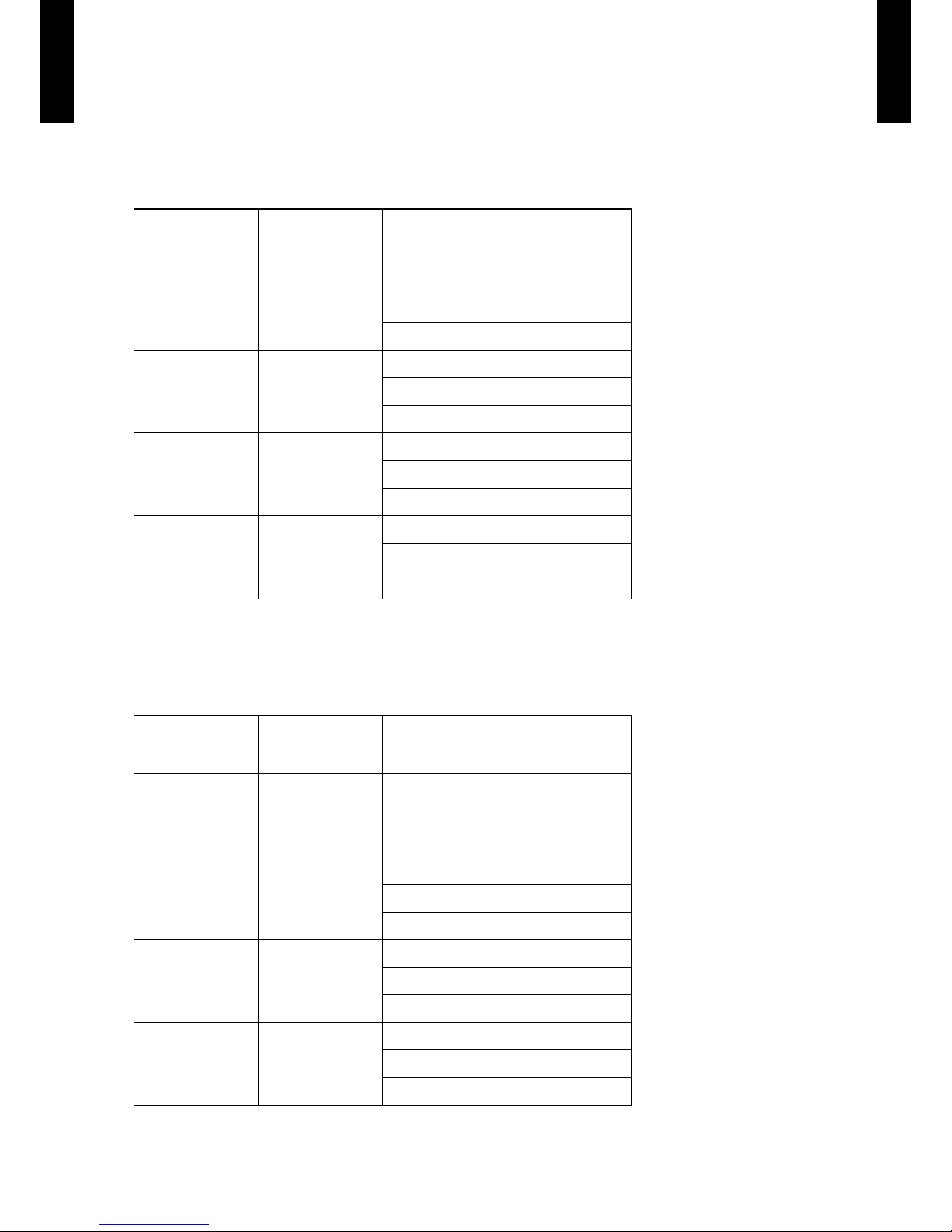
1-1. Setting the lter sign
The indoor unit has a sign to inform the user that it is time to clean the lter. Select the time setting
for the lter sign display interval in the table below according to the amount of dust or debris in the
room. If you do not wish the lter sign to be displayed, select the setting value for "No indication".
(. . .Factory setting)
Setting Description Function Number Setting Value
"Standard
(2,500 hours)"
11
00
"Long interval
(4,400 hours)"
01
"Short interval
(1,250 hours)"
02
No indication 03
1-2. Setting the ceiling height
Select the setting values in the table below according to the height of the ceiling.
(. . .Factory setting)
Setting Description Function Number Setting Value
Standard
3.2m
20
00
Low ceiling
2.7m
01
High ceiling
4.2m
02
The ceiling height values are for the 4-way outlet.
Do not change this setting in the 3-way outlet mode.
1-3. Setting the outlet directions
Select the setting values in the table below for using a 3-way outlet.
(. . .Factory setting)
Setting Description Function Number Setting Value
4-way
22
00
3-way 01
Page 40

- (01 - 37) -
CASSETTE TYPE
AU
A45-54LC
CASSETTE TYPE
AU
A45-54LC
1-4. Setting the vertical wind direction adjustment range
•The use of “upward” is recommended if you wish to prevent draft.
(The unit is factory-set to “00”)
•Note that the ceiling may become dirty depending on your usage condition.When this happens,
we recommend the use of the optional “PANEL SPACER KIT”.
(. . .Factory setting)
Setting Description Function Number Setting Value
Standard
23
00
upward 01
•We recommend the use of “upward” when using “High ceiling mode”.
upward
1-5. Setting the Cooler Room Temperature Correction
Depending on the installed environment, the room temperature sensor may require a correction.
The settings may be selected as shown in the table below.
(. . .Factory setting)
Setting Description Function Number Setting Value
Standard
30
00
Lower control 01
1-6. Setting the Heater Room Temperature Correction
Depending on the installed environment, the room temperature sensor may require a correction.
The settings may be changed as shown in the table below.
(. . .Factory setting)
Setting Description Function Number Setting Value
Standard
31
00
Lower control 01
Slightly warmer control 02
Warmer control 03
1-7. Auto Restart
The following settings are also possible, depending on the operating conditions.
(. . .Factory setting)
Setting Description Function Number Setting Value
Yes
40
00
No 01
1-8. Indoor Room Temperature Sensor Switching Function
(Only for Wired remote controller)
The following settings are needed when use the control by Wired remote controller temperature
sensor.
(. . .Factory setting)
Setting Description Function Number Setting Value
No
42
00
Yes 01
If setting value is “00”,
•
room temperature is controlled by the indoor unit temperature sensor.
If setting value is “01”,
•
room temperature is controlled by either indoor unit temperature sensor or remote controller unit sensor.
Page 41

- (01 - 38) -
CASSETTE TYPE
AU
A45-54LC
CASSETTE TYPE
AU
A45-54LC
WIRED REMOTE CONTROLLER12-3.
SWITCH POSITION
DIP SWITCH SETTING
1. Dual remote controller setting
Set the remote controller DIP switch No.2 according to the following table.
2. Memory backup setting
Set to ON to use batteries for the memory backup. If batteries are not used, all of the settings
stored in memory will be deleted if there is a power failure.
DIP SW
1 Can not be used. (Do not change)
2 Dual remote controller setting
3 Can not be used. (Do not change)
4 Can not be used. (Do not change)
5 Can not be used. (Do not change)
6 Memory backup setting
ON
ON
OFF
1
2
3
4
5
6
Front case (back side)
Do not use this
DIP Switch
DIP Switch
(
Factory setting)
Number
of remote
controller
Master unit Slave unit
DIP-SW No.2 DIP-SW No.2
1 (Normal) OFF
―
2 (Dual) OFF ON
(
Factory setting)
DIP-SW
No.6
Memory backup
OFF Invalidity
ON Validity
Page 42

- (01 - 39) -
CASSETTE TYPE
AU
A45-54LC
CASSETTE TYPE
AU
A45-54LC
OPTIONAL PARTS13.
Exterior Parts name Model No. Summary
Air outlet
shutter plate
UTR-YDZC
Air outlet shutter plate is
installed at the air outlet
when 3-way direction is
performed.
Wide panel UTG-AGYA-W
Wide panel hides the gap
between the ceiling hole and
the Decoration panel.
Panel spacer UTG-BGYA-W
Installation in a space of
256mm or greater is possible
by using panel spacer when
the height behind the ceiling
is low.
(Normal behind the ceiling
installation height is 298mm.)
IR Receiver kit UTY-LRHA1
Unit control is performed by
wireless remote controller
Wired remote
controller
UTB-UD
Unit control is performed by
wired remote controller
Insulation kit
for high
humidity
UTZ-KXGA
Install when the under roof
condition is expected to be
the humidity of over 80% and
the temperature of over 30
°C
External
connect kit
UTY-XWZX
Use to connect with various
peripheral devices and air
conditioner PC board.
( x 1 ) ( x 2 )
( x 1 ) ( x 2 )
External
control set
UTD-ECS5A
Use to connect with various
peripheral devices and air
conditioner PC board.
(Set of 6)
Page 43

- (01 - 40) -
CASSETTE TYPE
AU
A45-54LC
CASSETTE TYPE
AU
A45-54LC
Exterior Parts name Model No. Summary
Fresh air intake
kit
UT Z-V XGA
It can be taken in fresh air of
up to 10% of “high” air volume
of the indoor unit by attaching
Fresh Air Intake Kit to cassette
type indoor unit.
Page 44

D2D_AO052E/01
2009.04.30
SINGLE TYPE :
AOA45LBTL
2. OUTDOOR UNIT
Page 45

CONTENTS
2. OUTDOOR UNIT
2-1. SPECIFICATIONS
.......................................................................................... 02-01
2-2. DIMENSIONS
..................................................................................................... 02-02
2-3. REFRIGERANT CIRCUIT
......................................................................... 02-03
2-4. WIRING DIAGRAMS
.................................................................................... 02-04
2-5. CAPACITY COMPENSATION RATE FOR PIPE LENGTH
AND HEIGHT DIFFERENCE
................................................................. 02-05
2-6. ADDITIONAL CHARGE CALCULATION
..................................... 02-06
2-7. AIR FLOW
............................................................................................................02-07
2-8. OPERATION NOISE
..................................................................................... 02-08
2-8-1. NOISE LEVEL CURVE
................................................................................. 02-08
2-8-2. SOUND LEVEL CHECK POINT
.................................................................02-09
2-9. ELECTRIC CHARACTERISTICS
....................................................... 02-10
2-10. SAFETY DEVICES
......................................................................................... 02-11
Page 46

- (02 - 01) -
OUTDOOR UNIT
AO
A45L
OUTDOOR UNIT
AO
A45L
SPECIFICATIONS2-1.
Note :
Specicati ons are based on the f ollowing conditions.
Coolin g : Indoor temperature of 27 ˚CD B / 19 ˚CWB.an d outdoo r temper ature of 35 ˚CDB / 24 ˚CWB.
Heating : Indoor temperature of 20 ˚CD B / 15 ˚CWB.and outdoor temperature of 7 ˚CD B / 6 ˚CWB.
Pipe leng th : 7.5 m, Height differe nce : 0 m.(Out door uni t - Indoor unit)
Type INVERTER HEATPUMP
Model name AOA45LBTL
Power source 230V ~ 50Hz
Available voltage range 198-264V ~ 50Hz
Starting current A 15.0
Fan
Airow
rate
Cooling
m3/h
6600
Heating 6600
Type × Q'ty Propeller × 2
Motor output W 103 × 2
Sound pressure level
Cooling
dB(A)
55
Heating 56
Heat exchanger type
Dimensions (H × W × D)
mm
1260 × 900 × 36.4
Fin pitch 1.30
Rows x Stages 2 × 60
Pipe type Copper
Fin type Aluminium
Compressor
Type × Q'ty Twin Rotary × 1
Motor output W 3750
Refrigerant
Type R410A
Charge g 3350
Refrigerant oil Type POE
Enclosure
Material Steel sheet
Colour
BEIGE
( Approximate colour of MUNSELL 10 YR 7.5 / 1.0 )
Dimensions
( H×W×D)
Net
mm
1290 × 900 × 330
Gross 1430 × 1050 × 445
Weight
Net
kg (lb.)
98 ( 216 )
Gross 107 ( 236 )
Connection
pipe
Size
Liquid
mm
Ø 9.52 (Ø 3/8 in.)
Gas Ø 15.88 (Ø 5/8 in.)
Method Flare
Max. length
m
50(chargeless:20)
Max. height difference 30
Operation range
Cooling
˚C
-15 to 46
Heating -15 to 24
Page 47

- (02 - 02) -
OUTDOOR UNIT
AO
A45L
OUTDOOR UNIT
AO
A45L
DIMENSIONS2-2.
MODEL : AOA45L
(Unit : mm)
MOUNTING POSITION
900
1290
77 31
21
370
9
400
650
151
99
196
170
4-Ø12mm hole
12330
Air flow
Drain cap
mounting places
Top view
Side view
Bottom view
Front view
When there are obstacles
at the back or front side.
When there are obstacles
at the back and front
sides.
When there are obstacles
at the back, side(s), and
top.
When there are obstacles at the
back side with the installation
of more than one unit.
100 mm
or more
600 mm
or more
250 mm
or more
250 mm
or more
300 mm
or more
250 mm or more
(Service space)
300 mm
or more
100 mm
or more
100 to 300 mm *
600 to 1000 mm
* If the spac e is larg er than th at is stated, the co nditio n will be the same as t hat there are no obstacles.
Page 48

- (02 - 03) -
OUTDOOR UNIT
AO
A45L
OUTDOOR UNIT
AO
A45L
REFRIGERANT CIRCUIT2-3.
MODEL : AOA45L
Page 49

- (02 - 04) -
OUTDOOR UNIT
AO
A45L
OUTDOOR UNIT
AO
A45L
WIRING DIAGRAMS2-4.
MODEL : AOA45L
Page 50

- (02 - 05) -
OUTDOOR UNIT
AO
A45L
OUTDOOR UNIT
AO
A45L
CAPACITY COMPENSATION RATE FOR PIPE LENGTH 2-5.
AND HEIGHT DIFFERENCE
This table is created using the maximum capacity.
MODEL : AOA45L
COOLING
Pipe length (m)
5 7.5 10 20 30 40 50
Height
difference H
(m)
1
Indoor unit is upper
than outdoor unit.
30 – – – – 0.893 0.890 0.870
20 – – – 0.919 0.908 0.905 0.885
10 – – 0.979 0.934 0.923 0.920 0.899
7.5 – 0.988 0.983 0.938 0.927 0.924 0.903
5 1.001 0.992 0.987 0.942 0.931 0.927 0.907
0 1.009 1.000 0.995 0.949 0.938 0.935 0.914
2
Indoor unit is under
than outdoor unit
-5 1.009 1.000 0.995 0.949 0.938 0.935 0.914
-7.5 – 1.000 0.995 0.949 0.938 0.935 0.914
-10 – – 0.995 0.949 0.938 0.935 0.914
-20 – – – 0.949 0.938 0.935 0.914
-30 – – – – 0.938 0.935 0.914
HEATING
Pipe length (m)
5 7.5 10 20 30 40 50
Height
difference H
(m)
1
Indoor unit is upper
than outdoor unit.
30 – – – – 0.971 0.950 0.927
20 – – – 0.985 0.971 0.950 0.927
10 – – 1.016 0.985 0.971 0.950 0.927
7.5 – 1.000 1.016 0.985 0.971 0.950 0.927
5 0.978 1.000 1.016 0.985 0.971 0.950 0.927
0 0.978 1.000 1.016 0.985 0.971 0.950 0.927
2
Indoor unit is under
than outdoor unit
-5
0.973 0.995
1.011
0.980 0.966
0.945 0.923
-7.5
– 0.993
1.009
0.978 0.963
0.943 0.920
-10 – – 1.006 0.975 0.961 0.940 0.918
-20 – – – 0.966 0.951 0.931 0.909
-30 – – – – 0.942 0.921 0.899
Outdoor unit
Indoor unit
Connec tion pipe
2 Indoor unit is under than outdoor unit.
H
Indoor unit
Outdoor unit
Connec tion pipe
1 Indoor unit is upper than outdoor unit.
H
Height difference H
Page 51

- (02 - 06) -
OUTDOOR UNIT
AO
A45L
OUTDOOR UNIT
AO
A45L
ADDITIONAL CHARGE CALCULATION2-6.
MODEL : AO
A45L
Refrigerant charge
z
Refrigerant type R410A
Refrigerant amount g 3350
Pipe length m ~ 20 30 40 50
50g/m
Additional charge g 0 (Chargeless) +500 +1000 +1500
Page 52

- (02 - 07) -
OUTDOOR UNIT
AO
A45L
OUTDOOR UNIT
AO
A45L
AIR FLOW2-7.
MODEL : AOA45L
Cooling
z
Heating
z
Number of
rotations
(r.p.m)
Air ow
Upper fan 850
m
3
/h 6600
l/s 1833
Lower fan 750
CFM 3884
Number of
rotations
(r.p.m)
Air ow
Upper fan 850
m
3
/h 6600
l/s 1833
Lower fan 750
CFM 3884
Page 53

- (02 - 08) -
OUTDOOR UNIT
AO
A45L
OUTDOOR UNIT
AO
A45L
OPERATION NOISE2-8.
2-8-1. NOISE LEVEL CURVE
MODEL : AOA45L
Heating
z
Octave ba nd soun d pressu re level, d B:(0dB= 0.00 02µba r)
Octave ba nd center frequ ency,Hz
80
70
60
50
40
30
20
10
0
63 125 250 500 1,000 2,00 0 4,00 0 8,000
NC-65
NC-60
NC-55
NC-50
NC-45
NC-40
NC-35
NC-30
NC-25
NC-20
NC -15
Cooling
z
Octave ba nd soun d pressu re level, d B:(0dB= 0.00 02µba r)
Octave ba nd center frequ ency,Hz
80
70
60
50
40
30
20
10
0
63 125 250 500 1,000 2,00 0 4,00 0 8,000
NC-65
NC-60
NC-55
NC-50
NC-45
NC-40
NC-35
NC-30
NC-25
NC-20
NC -15
Page 54

- (02 - 09) -
OUTDOOR UNIT
AO
A45L
OUTDOOR UNIT
AO
A45L
2-8-2. SOUND LEVEL CHECK POINT
Microphone
Microphone
Air Fiow
1m
Page 55

- (02 - 10) -
OUTDOOR UNIT
AO
A45L
OUTDOOR UNIT
AO
A45L
ELECTRIC CHARACTERISTICS2-9.
*1) Wiring Spec. :
Selected Sample
(Selected based on Japan Electrotechnical Standard and Codes Committee E0005)
*2) Limited Wiring length :
This is the wiring length in case voltage descent is less than 2%.
When the wiring length becomes long, please select the wiring of a more larger diameter.
Model Name AOA45L
Power Supply
Voltage V 230 ~
Frequency Hz 50
Max. Operating Current A 20.0
Starting Current A 15.0
*1) Wiring Spec.
Main Fuse (Circuit breaker) Current A 30
Power Cable mm
2
5.3 - 6.0
*2)Limited wiring length m 17
Page 56

- (02 - 11) -
OUTDOOR UNIT
AO
A45L
OUTDOOR UNIT
AO
A45L
SAFETY DEVICES2-10.
Protection form
Model
AOA45L
Circuit protection
Current fuse (NEAR THE TERMINAL) 25A 250V
Current fuse (NEAR THE TERMINAL) 10A 250V
Current fuse (MAIN PRINTED CIRCUIT BOARD) 5A 250V
Current fuse (MAIN PRINTED CIRCUIT BOARD) 3.15A 250V
Fan motor protection Thermal protection program
OFF : 130±20°C
ON : 100±20°C
High Pressure Protection High Pressure Switch
OFF : 4.2±0.1MPa
ON : 3.2±0.15MPa
Compressor protection
Thermal protection program (COMPRESSOR TEMP.)
OFF : 110°C
ON : 80°C
Thermal protection program (DISCHARGE TEMP.)
OFF : 115°C
ON : After 7 minutes
Page 57

DTR_AO081E_01
2011.03.01
SINGLE TYPE :
AOA45LCTL
AOA54LCTL
2. OUTDOOR UNIT
Page 58

OUTDOOR UNIT
AO
A45-54LC
OUTDOOR UNIT
AO
A45-54LC
2. OUTDOOR UNIT
CONTENTS
1. SPECIFICATIONS
······························································································ 02 - 01
2. DIMENSIONS
········································································································ 02 - 02
3. INSTALLATION PLACE
················································································ 02 - 03
3-1. SINGLE OUTDOOR UNIT INSTALLATION
················································· 02 - 03
3-2. MULTIPLE OUTDOOR UNIT INSTALLATION
············································ 02 - 04
3-3. OUTDOOR UNIT INSTALLATION IN MULTI ROW
··································· 02 - 04
4. REFRIGERANT CIRCUIT
············································································ 02 - 05
5. WIRING DIAGRAMS
······················································································· 02 - 06
6. CAPACITY COMPENSATION RATE FOR PIPE LENGTH
AND HEIGHT DIFFERENCE
····································································· 02 - 07
7. ADDITIONAL CHARGE CALCULATION
········································ 02 - 09
8. AIR FLOW
················································································································ 02 - 10
9. OPERATION NOISE
·························································································02 - 11
9-1. NOISE LEVEL CURVE
························································································02 - 11
9-2. SOUND LEVEL CHECK POINT
········································································02 - 12
10. ELECTRIC CHARACTERISTICS
···························································02 - 13
11. SAFETY DEVICES
·····························································································02 - 14
12. EXTERNAL INPUT & OUTPUT
·······························································02 - 15
12-1. EXTERNAL INPUT
································································································02 - 15
12-2. EXTERNAL OUTPUT
···························································································02 - 17
13. FUNCTION SETTING
······················································································ 02 - 19
13-1. FIELD SETTING SWITCHES
············································································ 02 - 19
13-2. SETTING METHOD
····························································································· 02 - 20
13-2-1. LOW NOISE MODE ······················································································· 02 - 20
13-2-2. PEAK CUT MODE ························································································· 02 - 21
14. OPTIONAL PARTS
··························································································· 02 - 22
Page 59

- (02 - 01) -
OUTDOOR UNIT
AO
A45-54LC
OUTDOOR UNIT
AO
A45-54LC
SPECIFICATIONS1.
Note :
Speci cations are base d on the fol lowing c onditi ons.
Coolin g : Indoor t emperat ure of 27 °CD B / 19 °CWB.a nd outdo or temper ature of 3 5 °CDB/ 24 °CWB.
Heating : I ndoor te mperat ure of 20 °CD B / 15 °CWB.a nd outdoo r temper ature of 7 °C DB/6 °CW B.
Pipe leng th : 5 m, Heig ht diffe rence : 0 m. (Outdoor u nit - Indo or unit)
Model na me AOA45LCTL AOA54LC TL
Power source 1Ø 230V~ 50 Hz
Available voltage r ange 198 -264V~ 50Hz
Starting cur rent A 18.9 20.9
Fan
Airow
rate
Cooling
(m
3
/h)
6,750 6,750
Heating 6,200 6,850
Type × Q'ty P ropeller × 2
Motor out put W 10 4 104
Sound pressure level
Cooling
dB(A)
55 55
Heating 55 57
Heat exchanger ty pe
Dimensions (H × W × D)
mm
1260 × 900 × 36.4
Fin pitch 1.30
Rows x Stag es 2 × 60
Pipe typ e Copper
Fin type
Type (Material) C orrugate (Alu minium)
Surfa ce treatment Cor rosion resist ance (Blue n)
Compressor
Type × Q'ty Twin Rotar y × 1
Motor out put W 2100
Refrigerant
Typ e R410 A
Charge g 3350
Refrigerant oil Ty pe RB68
Enclosu re
Material Steel she et
Colour
BEIGE
( Approximate colour of MU NSELL 10YR 7.5 / 1.0 )
Dimensions
( H×W×D)
Net
mm
1290 × 90 0 × 330
Gross 1430 × 1050 × 4 45
Weight
Net
kg(lbs.)
86 (190)
Gross 94 (208)
Connec tion pipe
Size
(Standard)
Liquid
mm
Ø 9.52 (Ø 3/8 in.)
Gas Ø 15.88 (Ø 5/8 in.)
Method Flare
Pre- charge length
m
20
Max. length 50
Max. height dif ferenc e 30
Operat ion range
Cooling
°C
-15 to 46
Heating -15 to 24
Page 60

- (02 - 02) -
OUTDOOR UNIT
AO
A45-54LC
OUTDOOR UNIT
AO
A45-54LC
DIMENSIONS2.
MODEL : AOA45LC, AOA54LC
(Unit : mm)
45
66
(
370
)
38
(Liquid)
46
(
Gas
)
40
650 11 9132
1290
900
21
9
Ø28
(Cable port)
Pipe port
87
131
25
543
(
Gas valve
)
540
(Liquid valve)
Ø28
(Cable port)
3-way valve
(
Gas
)
3-way valve
(
Liquid
)
Terminal blocks
21
50
330
31
12
Ø28
(Cable port)
21
55
50
156
112
Ø28
(Cable port)
Pipe port
A
188
265
302
400
51.5
440
625
330
31
89
95
120
50
95
167
21
67
Ø28
(Cable port)
Ø28 (Cable port)
Pipe port
Front view
Bottom view
Side view Rear view
Detail A
1446
1654
Pipe & cable port
Top view
Page 61

- (02 - 03) -
OUTDOOR UNIT
AO
A45-54LC
OUTDOOR UNIT
AO
A45-54LC
INSTALLATION PLACE3.
SINGLE OUTDOOR UNIT INSTALLATION3-1.
WHEN THE UPWARD AREA IS OPEN
(Unit : mm)
Obstacles at rear
only
Obstacles at rear and
sides only
Obstacles at front
only
150
200
200
300
1000 or more
Obstacles at front and
rear only
1000 or more
150
WHEN AN OBSTRUCTION IS PRESENT ALSO IN THE UPWARD AREA
(Unit : mm)
Obstacles at rear and
above only
Obstacles at rear, sides, and above only
Max. 500
300
1000
Max. 500
500
250
250
1500
Page 62

- (02 - 04) -
OUTDOOR UNIT
AO
A45-54LC
OUTDOOR UNIT
AO
A45-54LC
MULTIPLE OUTDOOR UNIT INSTALLATION3-2.
WHEN THE UPWARD AREA IS OPEN
(Unit : mm)
Obstacles at rear only Obstacles at front only Obstacles at front and rear
only
300
1500 or more
500
1500 or more
WHEN AN OBSTRUCTION IS PRESENT ALSO IN THE UPWARD AREA
(Unit : mm)
Obstacles at rear and above only
1500
1500
500
Max. 300
OUTDOOR UNIT INSTALLATION IN MULTI ROW3-3.
(Unit : mm)
Single parallel unit arrangement Multiple parallel unit arrangement
1000
2000 or more
600
150
3000 or more
600
1500
500
Page 63

- (02 - 05) -
OUTDOOR UNIT
AO
A45-54LC
OUTDOOR UNIT
AO
A45-54LC
REFRIGERANT CIRCUIT4.
MODEL : AOA45LC, AOA54LC
Page 64

- (02 - 06) -
OUTDOOR UNIT
AO
A45-54LC
OUTDOOR UNIT
AO
A45-54LC
WIRING DIAGRAMS5.
MODEL : AOA45LC, AOA54LC
Page 65

- (02 - 07) -
OUTDOOR UNIT
AO
A45-54LC
OUTDOOR UNIT
AO
A45-54LC
CAPACITY COMPENSATION RATE FOR PIPE LENGTH 6.
AND HEIGHT DIFFERENCE
MODEL : AOA45LC
Height difference H
HH
1 Indoor unit is upper than outdoor unit.
2 Indoor unit is under than outdoor unit.
Outdoor unit
Outdoor unit
Connection pipe
Indoor unit
Indoor unit
Connection pipe
HEATING
Pipe length (m)
5 7. 5 10 20 30 40 50
Height
difference H
(m)
Û
1
Indoor unit is
upper than
outdoor unit.
30 - - - - 0.978 0.968 0.958
20 - - - 0.988 0.978 0.968 0.958
10 - - 0.998 0.988 0.978 0.968 0.958
7. 5 - 1.000 0.998 0.988 0.978 0.968 0.958
5 1.000 1.000 0.998 0.988 0.978 0.968 0.958
0 1.000 1.000 0.998 0.988 0.978 0.968 0.958
Û
2
Indoor unit is
under than
outdoor unit.
-5 0.998 0.995 0.993 0.983 0.973 0.963 0.953
-7. 5 - 0.993 0.991 0.9 81 0.971 0.9 61 0.951
-10 - - 0.988 0.978 0.968 0.958 0.948
-20 - - - 0.968 0.958 0.949 0.939
-30 - - - - 0.949 0.939 0.929
COOLING
Pipe length (m)
5 7. 5 10 20 30 40 50
Height
difference H
(m)
Û
1
Indoor unit is
upper than
outdoor unit.
30 - - - - 0.879 0.846 0.814
20 - - - 0.926 0.893 0.861 0.828
10 - - 0.975 0.942 0.908 0.875 0 . 8 41
7. 5 - 0.988 0.979 0.946 0.912 0.878 0.845
5 0.992 0.992 0.983 0.949 0.916 0.882 0.848
0 1.000 1.000 0.991 0.957 0.923 0.889 0.855
Û
2
Indoor unit is
under than
outdoor unit.
-5 1.000 1.000 0.991 0.957 0.923 0.889 0.855
-7. 5 - 1.000 0.991 0.957 0.923 0.889 0.855
-10 - - 0.991 0.957 0.923 0.889 0.855
-20 - - - 0.957 0.923 0.889 0.855
-30 - - - - 0.923 0.889 0.855
Page 66

- (02 - 08) -
OUTDOOR UNIT
AO
A45-54LC
OUTDOOR UNIT
AO
A45-54LC
MODEL : AOA54LC
Height difference H
HH
1 Indoor unit is upper than outdoor unit.
2 Indoor unit is under than outdoor unit.
Outdoor unit
Outdoor unit
Connection pipe
Indoor unit
Indoor unit
Connection pipe
HEATING
Pipe length (m)
5 7. 5 10 20 30 40 50
Height
difference H
(m)
Û
1
Indoor unit is
upper than
outdoor unit.
30 - - - - 0.978 0.968 0.958
20 - - - 0.988 0.978 0.968 0.958
10 - - 0.998 0.988 0.978 0.968 0.958
7. 5 - 1.000 0.998 0.988 0.978 0.968 0.958
5 1.000 1.000 0.998 0.988 0.978 0.968 0.958
0 1.000 1.000 0.998 0.988 0.978 0.968 0.958
Û
2
Indoor unit is
under than
outdoor unit.
-5 0.998 0.995 0.993 0.983 0.973 0.963 0.953
-7. 5 - 0.993 0.991 0.981 0.971 0.961 0.9 51
-10 - - 0.988 0.978 0.968 0.958 0.948
-20 - - - 0.968 0.958 0.949 0.939
-30 - - - - 0.949 0.939 0.929
COOLING
Pipe length (m)
5 7. 5 10 20 30 40 50
Height
difference H
(m)
Û
1
Indoor unit is
upper than
outdoor unit.
30 - - - - 0.871 0.837 0.803
20 - - - 0.921 0.886 0. 851 0.816
10 - - 0.971 0.936 0.900 0.865 0.830
7. 5 - 0.988 0.975 0.940 0.904 0.868 0.833
5 0.992 0.992 0.979 0.943 0.908 0.872 0.836
0 1.000 1.000 0.987 0.951 0.915 0.879 0.843
Û
2
Indoor unit is
under than
outdoor unit.
-5 1.000 1.000 0.987 0.951 0.915 0.879 0.843
-7. 5 - 1.000 0.987 0.951 0.915 0.879 0.843
-10 - - 0.987 0. 9 51 0.915 0.879 0.843
-20 - - - 0.951 0.915 0.879 0.843
-30 - - - - 0.915 0.879 0.843
Page 67

- (02 - 09) -
OUTDOOR UNIT
AO
A45-54LC
OUTDOOR UNIT
AO
A45-54LC
ADDITIONAL CHARGE CALCULATION7.
MODEL : AOA45LC, AOA54LC
REFRIGERANT CHARGE
z
Refrigerant type R 410A
Refrigerant amount g 3,350
Total pipe length m 20 or less 30 40 50 (MAX)
40g/m
Additional charge g 0 400 800 1200
Page 68

- (02 - 10) -
OUTDOOR UNIT
AO
A45-54LC
OUTDOOR UNIT
AO
A45-54LC
AIR FLOW8.
MODEL : AOA45LC, AOA54LC
Cooling
z
Heating
z
MODEL
Number of
rotations
(r.p.m.)
Air ow
AOA45LC
Upper fan 850
m
3
/h 6750
l/s 1875
Lower fan 800
CFM 3974
AOA54LC
Upper fan 850
m
3
/h 6750
l/s 1875
Lower fan 800
CFM 3974
MODEL
Number of
rotations
(r.p.m.)
Air ow
AOA45LC
Upper fan 780
m
3
/h 6200
l/s 172 2
Lower fan 750
CFM 3650
AOA54LC
Upper fan
850
m3/h
6850
l/s
1903
Lower fan
830
CFM
4033
Page 69

- (02 - 11) -
OUTDOOR UNIT
AO
A45-54LC
OUTDOOR UNIT
AO
A45-54LC
OPERATION NOISE9.
NOISE LEVEL CURVE9-1.
MODEL : AOA45LC
Cooling
z
Octave ba nd soun d pressu re level, d B:(0dB= 0.00 02µba r)
Octave ba nd center frequ ency,Hz
80
70
60
50
40
30
20
10
0
63 125 250 500 1,000 2,00 0 4,00 0 8,000
NC-65
NC-60
NC-55
NC-50
NC-45
NC-40
NC-35
NC-30
NC-25
NC-20
NC -15
Heating
z
Octave ba nd soun d pressu re level, d B:(0dB= 0.00 02µba r)
Octave ba nd center frequ ency,Hz
80
70
60
50
40
30
20
10
0
63 125 250 500 1,000 2,00 0 4,00 0 8,000
NC-65
NC-60
NC-55
NC-50
NC-45
NC-40
NC-35
NC-30
NC-25
NC-20
NC -15
Heating
z
Octave ba nd soun d pressu re level, d B:(0dB= 0.00 02µba r)
Octave ba nd center frequ ency,Hz
80
70
60
50
40
30
20
10
0
63 125 250 500 1,000 2,00 0 4,00 0 8,000
NC-65
NC-60
NC-55
NC-50
NC-45
NC-40
NC-35
NC-30
NC-25
NC-20
NC -15
Octave ba nd soun d pressu re level, d B:(0dB= 0.00 02µba r)
Octave ba nd center frequ ency,Hz
80
70
60
50
40
30
20
10
0
63 125 250 500 1,000 2,00 0 4,00 0 8,000
MODEL : AOA54LC
Cooling
z
NC-65
NC-60
NC-55
NC-50
NC-45
NC-40
NC-35
NC-30
NC-25
NC-20
NC -15
Page 70

- (02 - 12) -
OUTDOOR UNIT
AO
A45-54LC
OUTDOOR UNIT
AO
A45-54LC
SOUND LEVEL CHECK POINT9-2.
Microphone
1m
Microphone
Air Flow
Page 71

- (02 - 13) -
OUTDOOR UNIT
AO
A45-54LC
OUTDOOR UNIT
AO
A45-54LC
ELECTRIC CHARACTERISTICS10.
Model name AOA45LC AOA54LC
Power supply
Voltage V 230 ~
Frequency Hz 50
*1) Max. operating current A 22.5 23.5
*2) Wiring spec.
Main fuse (Circuit breaker)
Current
A 30
Power cable mm
2
6.0
*1) The maximum current is the total current of indoor unit and outdoor unit.
*2) Wiring spec. :
Selected sample
(Selected based on Japan Electrotechnical Standard and Codes Committee E0005)
Page 72

- (02 - 14) -
OUTDOOR UNIT
AO
A45-54LC
OUTDOOR UNIT
AO
A45-54LC
SAFETY DEVICES11.
Protection form
Model
AOA45LC AOA54LC
Circuit protection
Current fuse
(Filter printed circuit board)
10A 250V, 3.15A 250V
Current fuse
(Main printed circuit board)
3.15A 250V
Fan motor protector Thermal protector
OFF : 150±15°C
ON : 120±15°C
Compressor protection
Thermal protection program
(Compressor temp.)
OFF : 108°C
ON : 80°C
Thermal protection program
(Discharge temp.)
OFF : 110°C
ON : After 7 minutes
High pressure protection Pressure switch
OFF : 4.2±0.1MPa
ON : 3.2±0.15MPa
Low pressure protection Pressure sensor
OFF : 0.12MPa
ON : 0.15MPa
Page 73

- (02 - 15) -
OUTDOOR UNIT
AO
A45-54LC
OUTDOOR UNIT
AO
A45-54LC
EXTERNAL INPUT & OUTPUT12.
EXTERNAL INPUT12-1.
ON/OFF of the "Low noise mode" and "Peak cut mode" functions can be specied by external
signal.
LOW NOISE MODE
The following reduces the operating sound of the outdoor unit from the normal sound. •
The air conditioner is set to the "Low noise mode" when closing the contact input of a commercial
timer or ON/OFF switch to a connector on the outdoor control PC board.
* Performance may drop depending on the outside air temperature condition, etc.
Circuit diagram example
z
Outdoor unit
control PC board
Connector
1
2
Signal
Field supply
*10m
Connected unit
Ex.) Switch
Contact capacity : 24VDC or more, 10mA or more.
* Make the distance from the PC board to the connected unit within 10m.
Use the following parts and construct a circuit as shown above. •
Input Signal∙∙∙ON : Low noise mode, Input Signal∙∙∙OFF : Normal operation •
* Set the "Low noise mode" level, refer to "13.FUNCTION SETTING".
ON
OFF
ON
OFF
Input Signal
Low noise mode
Parts (Optional)
z
Parts name External connect kit
Model name UT Y-XW Z XZ3
Input Output Connector Remarks
Low noise mode ― CN10
See external
input/output settings
for details.
Peak cut mode ― CN11
― Error status CN12
― Compressor status CN13
Page 74

- (02 - 16) -
OUTDOOR UNIT
AO
A45-54LC
OUTDOOR UNIT
AO
A45-54LC
PEAK CUT MODE
Operation that suppressed the current value can be performed by means of the following on- •
site work. The air conditioner is set to the Peak cut mode when closing the contact input of a
commercial ON/OFF switch to a connector on the outdoor control PC board.
Circuit diagram example
z
Contact capacity : 24VDC or more, 10mA or more.
Outdoor unit
control PC board
Connector
1
2
Signal
Field supply
*10m
Connected unit
Ex.) Switch
* Make the distance from the PC board to the connected unit within 10m.
Use the following parts and construct a circuit as shown above. •
Input Signal∙∙∙ON : Peak cut mode, Input Signal∙∙∙OFF : Normal operation •
*Set the "Peak cut mode" level, refer to "13.FUNCTION SETTING".
ON
OFF
ON
OFF
Input Signal
Peak cut mode
Parts (Optional)
z
Parts name External connect kit
Model name UT Y-XW Z XZ3
Page 75

- (02 - 17) -
OUTDOOR UNIT
AO
A45-54LC
OUTDOOR UNIT
AO
A45-54LC
EXTERNAL OUTPUT12-2.
ERROR STATUS OUTPUT
An air conditioner error status signal is produced when a malfunction occurs. •
Circuit diagram example
z
1) Power supply
●Voltage (Chart sign=Vcc) : DC 24V or less
2) Load
● Load : DC 500mA or less is recommended
Signal
Outdoor unit
control PC board
Connected unit
Connector
1
2
Field supply
*10m
Vcc
+
+
-
Load
Vcc
Power
supply
* Make the distance from the PC board to the connected unit within 10m.
Error
Normal
ON
OFF
Error status
Output signal
Parts (Optional)
z
Parts name External connect kit
Model name UT Y-XW Z XZ3
Page 76

- (02 - 18) -
OUTDOOR UNIT
AO
A45-54LC
OUTDOOR UNIT
AO
A45-54LC
COMPRESSOR STATUS OUTPUT
Compressor operation status signal is produced when the compressor is running. •
Circuit diagram example
z
1) Power supply
●Voltage (Chart sign=Vcc) : DC 24V or less
2) Load
● Load : DC 500mA or less is rec ommended
Signal
Outdoor unit
control PC board
Connected unit
Connector
1
2
Field supply
*10m
Vcc
+
+
-
Load
Vcc
Power
supply
* Make the distance from the PC board to the connected unit within 10m.
ON
OFF
Operation
Stop
Compressor
Output signal
status
Parts (Optional)
z
Parts name External connect kit
Model name UT Y-XW Z XZ3
Page 77

- (02 - 19) -
OUTDOOR UNIT
AO
A45-54LC
OUTDOOR UNIT
AO
A45-54LC
FUNCTION SETTING13.
FIELD SETTING SWITCHES13-1.
The positions of the switches on the outdoor unit control board are shown in the gure below.
FUNCTIONS
Caution
Discharge the static electricity from your body before setting up the push buttons.
Never touch the terminals or the patterns on the parts that are mounted on the board.
Terminal blocks
Push
buttons
LED lamps
Display lamp Function or operation method
(1) POWER / MODE Green
Lights on while power on.
Local set ting in outdoor unit or error
code is displayed with blink.
(2) ERROR Red Blinks during abnormal operation.
(3) PUMP DOWN (L1) Orange
Lights on during pump down
operation.
(4) LOW NOISE MODE
(L2,L3)
Orange
Lights on during “Low noise” mode
when local setting is activated.
(Lighting pattern of L2 and L3
indicates low noise level)
(5) PEAK CUT MODE
(L4,L5,L6)
Orange
Lights on during “Peak cut” mode
when local setting is activated.
(Lighting pattern of L4, L5 and L6
indicates peak cut level)
Button Function or operation method
SW1 MODE
To switch between “Local setting”
and “Error code display”.
SW2 SELECT
To switch between the individual
“Local settings” and the “ Error c ode
displays”.
SW3 ENTER
To x between the individual “Local
settings” and the “Error code
displays”.
SW4 EXIT
To return to “Operation status
display”.
SW5
PUMP
DOWN
To start the pump down operation.
SW1
SW2
SW3 SW4 SW5
(1)
(2)
(3)
(4)
(5)
LED lamp
Page 78

- (02 - 20) -
OUTDOOR UNIT
AO
A45-54LC
OUTDOOR UNIT
AO
A45-54LC
SETTING METHOD13-2.
Stop the operation of air conditioner before this setting.
LOW NOISE MODE13-2-1.
SW1
SW2
SW3 SW4 SW5
LED lamp part
(1) Switch to “Local setting mode” by pressing [MODE] button (SW1) for 3 seconds or more.
(2) Conrm (POWER / MODE) blinks 9 times, and press [ENTER] button (SW3).
POWER
MODE
ERROR
(L1) (L2) (L3) (L4) (L5) (L6)
PUMP
DOWN
LOW NOISE PEAK CUT
Blinks
(9 times)
Sign “ ” : Lights off
(3) Press [SELECT] button (SW2), and adjust LED lamp as shown below. (Current setting is
displayed)
(L2)
(L3)
LOW NOISE
Blink
LOW NOISE
MODE
(4) Press [ENTER] button (SW3).
(L2) (L3)
LOW NOISE
LOW NOISE
MODE
Sign “ ” : Lights on
(5) Press [SELECT] button (SW2), and adjust LED lamp as shown in below gure.
PEAK CUT
MODE 1
MODE 2
Blink
Blink
(L4) (L5) (L6)
The noise of MODE2 is lower than one of MODE1.
(6) Press [ENTER] button (SW3) and x it.
PEAK CUT
MODE 1
MODE 2
(L4) (L5) (L6)
(7) Return to “Operating status display (Normal operation)” by pressing [EXIT] button (SW4).
• In case of missing how many times [SELECT] and [ENTER] button are pressed, restart from the beginning of operation
procedure after returning to “Operation status display (normal operation)” by pressing the [EXIT] button once.
Page 79

- (02 - 21) -
OUTDOOR UNIT
AO
A45-54LC
OUTDOOR UNIT
AO
A45-54LC
PEAK CUT MODE13-2-2.
SW1
SW2
SW3 SW4 SW5
LED lamp part
(1) Switch to “Local setting mode” by pressing [MODE] button (SW1) for 3 seconds or more.
(2) Conrm (POWER / MODE) blinks 9 times, and press [ENTER] button (SW3).
POWER
MODE
ERROR
(L1) (L2) (L3) (L4) (L5) (L6)
PUMP
DOWN
LOW NOISE PEAK CUT
Blinks
(9 times)
Sign “ ” : Lights off
(3) Press [SELECT] button (SW2), and adjust LED lamp as shown below. (Current setting is
displayed)
(L2)
(L3)
LOW NOISE
Blink
PEAK CUT
MODE
(4) Press [ENTER] button (SW3).
(L2) (L3)
LOW NOISE
PEAK CUT
MODE
Sign “ ” : Lights on
(5) Press [SELECT] button (SW2), and adjust LED lamp as shown in below gure.
100% of rated input ratio
75% of rated input ratio
50% of rated input ratio
0% of rated input ratio
Blink
Blink Blink
Blink
Blink
PEAK CUT
(L4) (L5) (L6)
(6) Press [ENTER] button (SW3) and x it.
100% of rated input ratio
75% of rated input ratio
50% of rated input ratio
0% of rated input ratio
PEAK CUT
(L4) (L5) (L6)
(7) Return to “Operating status display (Normal operation)” by pressing [EXIT] button (SW4).
• When pressed number is lost during operation, restart from the beginning of operation procedure after returning
to “Operation status display (normal operation)” by pressing the [EXIT] button once.
Page 80

- (02 - 22) -
OUTDOOR UNIT
AO
A45-54LC
OUTDOOR UNIT
AO
A45-54LC
OPTIONAL PARTS14.
Exterior Parts name Model No. Summary
External connect
kit
UTY-XWZXZ3
Use to operate the External input
and output function of Outdoor
unit.
 Loading...