

Fujitsu AR*C45LCTU series, AR*C54LCTU series, AO*A45LCTL series, AO*A54LCTL series Technical Manual
Page 1
DESIGN & TECHNICAL MANUAL
INDOOR
OUTDOOR
AOA45LCTL
AOA54LCTL
ARC45LCTU
ARC54LCTU
AIR CONDITIONER
Duct type
Page 2

1. INDOOR UNIT
DTR_AR049E_02
2013.11.08
DUCT TYPE :
ARC45LCTU
ARC54LCTU
Page 3

DUCT TYPE
AR
C45-54LC
DUCT TYPE
AR
C45-54LC
CONTENTS
1. INDOOR UNIT
1. FEATURE
............................................................................................................ 01 - 01
2. WIRED REMOTE CONTROLLER
................................................... 01 - 05
3. SPECIFICATIONS
........................................................................................ 01 - 08
4. DIMENSIONS
................................................................................................... 01 - 09
5. WIRING DIAGRAMS
...................................................................................01 - 11
6. CAPACITY TABLE
....................................................................................... 01 - 12
6-1. COOLING CAPACITY
................................................................................ 01 - 12
6-2. HEATING CAPACITY
................................................................................. 01 - 13
7. FAN PERFORMANCE AND CAPACITY
..................................... 01 - 14
8. OPERATION NOISE
................................................................................... 01 - 16
8-1. NOISE LEVEL CURVE
............................................................................... 01 - 16
8-2. SOUND LEVEL CHECK POINT
............................................................... 01 - 17
9. ELECTRIC CHARACTERISTICS
..................................................... 01 - 18
10. SAFETY DEVICES
....................................................................................... 01 - 19
11. EXTERNAL INPUT & OUTPUT
......................................................... 01 - 20
11-1. EXTERNAL INPUT
...................................................................................... 01 - 21
11-2. EXTERNAL OUTPUT
................................................................................. 01 - 22
12. FUNCTION SETTING
................................................................................ 01 - 26
12-1. INDOOR UNIT
.............................................................................................. 01 - 26
12-2. INDOOR UNIT (Setting by remote controller)
..................................... 01 - 28
12-3. WIRED REMOTE CONTROLLER
............................................................ 01 - 30
13. OPTIONAL PARTS
...................................................................................... 01 - 31
Page 4
- (01 - 01) -
DUCT TYPE
AR
C45-54LC
DUCT TYPE
AR
C45-54LC
FEATURE1.
MODEL
ARC45LCTU / AOA45LCTL
ARC54LCTU / AOA54LCTL
FEATURES
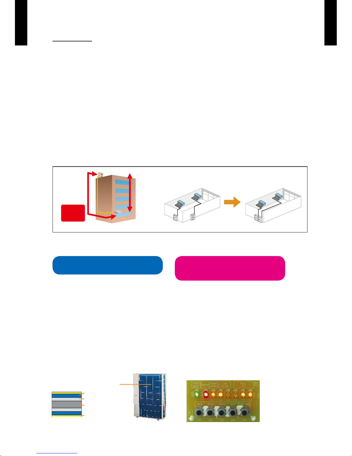
Improvement of market suitability
z
Considerable improvement of installation work by compact size and light weight considering with
the conditions of installation in the ceiling.
The size which the indoor unit can be installed in the spacing between the beams is required for
the installation in the ceiling.
Restriction for dimension of width and height.
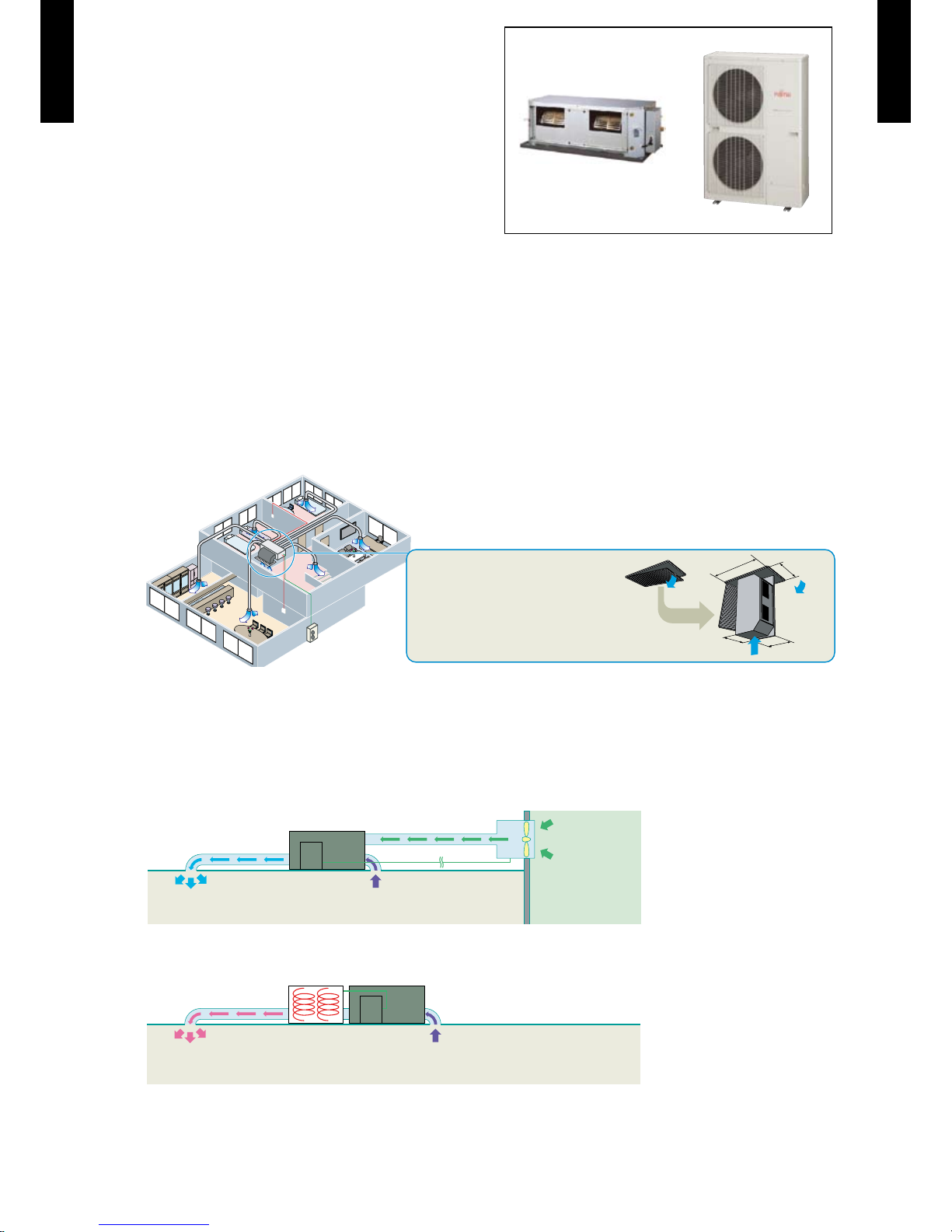
Indoor unit installation example
Correspondence to Network
z
Various networks can be constructed according to the user needs.
1.Fresh air output port
Fresh air is connected with the fan of an indoor unit.
2.Electrical heater output port
Electrical heater operates at the time of heating.
3.External input port
Start / Stop of the air conditioner can be changed from the external equipment.
Carrying-in example in the ceiling
Restriction for space when being carried
into the ceiling for replacement
(Ceiling intake grille)
500mm
400mm
750mm
550mm
Indoor Outdoor
Fresh air
Heater
Indoor
Page 5
- (01 - 02) -
DUCT TYPE
AR
C45-54LC
DUCT TYPE
AR
C45-54LC
Operation sound (Low noise)
z
FUNCTION SETTING
Room temperature sensor switching
z
Switches from room temperature judgment by room temperature sensor attached to indoor
unit body to room temperature judgment by room temperature sensor attached to wired remote
controller.
Economy operation
z
The power consumption can be reduced.
Powerful mode ...Standard
Soft mode ...Performs operation which reduces the power consumption
Auto restart
z
The units restart automatically when the current was returned even when
there was a power interruption during operation.
Cooling room temperature correction
z
Heating room temperature correction
z
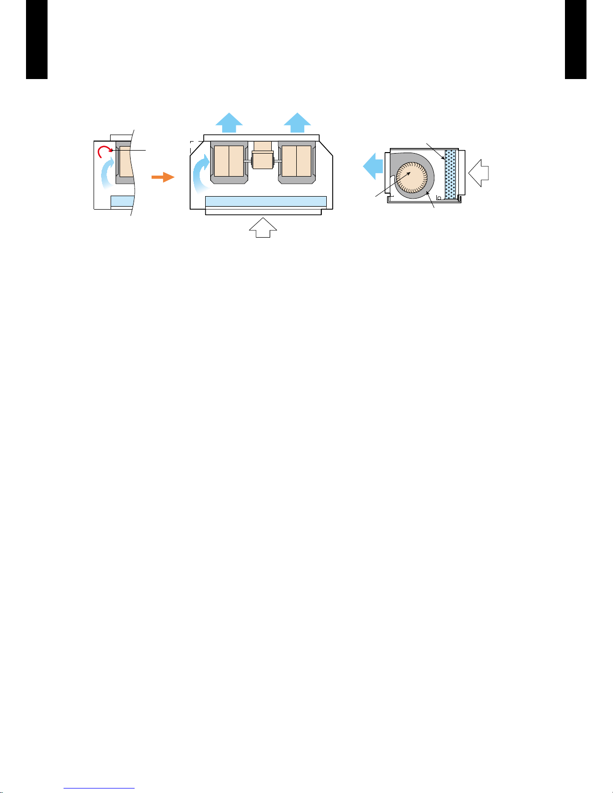
Heat exchanger
Plastic fan
Ø225 mm
Heat exchanger
Casing (Plastic)
Turbulent
air flow
Turbulent air ow is reduced by cutting off the corners of
conventional indoor unit front panel and fan case
Low noise is realized by adopting
plastic case, plastic fan
Page 6
- (01 - 03) -
DUCT TYPE
AR
C45-54LC
DUCT TYPE
AR
C45-54LC
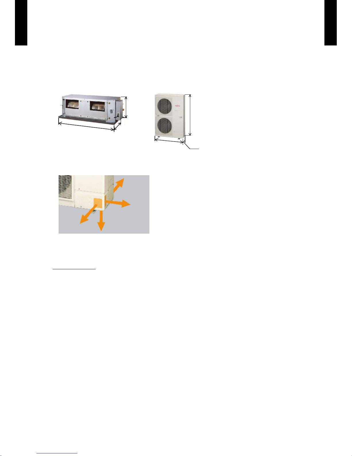
Space saving
z
Compact size •
High performance has been realized with a compact indoor / outdoor unit.
Due to the compact size of the indoor and outdoor unit, the installation space required
has been reduced allowing for a wider selection on installation locations.
1050
500
400
4-directions piping connection •
Four directions piping connection is possible. The perfect route can be selected
according to the installation.
Rear
Front
Lateral
Bottom
Quiet operation
z
OUTDOOR UNIT
Low noise mode (Optional parts: UTY-XWZXZ3)
Introduction of a low outdoor noise operation mode allow the outdoor unit to have two quiet mode
operation settings.
* Performance may drop depending on the outside air temperature condition, etc.
1) Level1 (Rated noise value -2dB)
2) Level2 (Rated noise value -4dB)
ARC45/54LC
OUTDOOR UNIT
900
330
1290
INDOOR UNIT
Page 7
- (01 - 04) -
DUCT TYPE
AR
C45-54LC
DUCT TYPE
AR
C45-54LC
Peak cut operation
z
Peak cut mode (Optional parts: UTY-XWZXZ3)
The introduction of a peak power consumption mode control 4 steps outdoor operation control to
cut down energy usage at peak energy usage times.
* Performance drops by reducing the power consumption preferentially.
Level 1 ... Performs operation which suppresses the power consumption to the rated power
consumption value (100%).
Level 2 ... Performs operation which suppresses the power consumption to 75% of the rated
power consumption value.
Level 3 ... Performs operation which suppresses the power consumption to 50% of the rated
power consumption value.
Level 4 ... Performs operation which suppresses the power consumption to almost 0% by stopping
the compressor.
High install ability long piping correspondence
z
Chargeless
20m
Max pipe
length
50m
Max height
difference
30m
Long piping provides an outdoor unit and indoor
unit layout margin.
Low outdoor air temperature correspondence
z
Both cooling and heating operations can be performed when the outdoor air temperature is low.
Cooling
-15 ºC
Heating
Dry-bulb
-15 ºC
Wet-bulb
-20 ºC
External output (option)
z
Compressor status output •
This output indicates the outdoor unit
compressor status.
Error status output •
This output indicates the outdoor unit and connected
indoor unit's Normal / Error.
Blue n heat exchanger
z
Corrosion-resistance of the heat exchanger
even in coastal areas has been improved by
blue n treatment of the outdoor unit heat
exchanger.
Blue n heat exchanger
Cobalt Blue protection
Standard chrom ate protection
Aluminium base material
Hydrophilic coating
Service, maintenance
z
"Error display" and "Operating information" •
can be explained by LED display.
Pump down operation can be performed by •
one button when refrigerant recovery.
•
Page 8
- (01 - 05) -
DUCT TYPE
AR
C45-54LC
DUCT TYPE
AR
C45-54LC
WIRED REMOTE CONTROLLER2.
FEATURES
Various timer setup (ON / OFF / WEEKLY) are possible.
Equipped with weekly timer as standard function.(2 times Start / Stop
per day for a week)
When setting up a timer, operation mode and a temperature setup
can be changed.
When a failure occurs,the error code is displayed. (Maximum of 16)
Error indication.(A maximum of 16 error histories are memorizable.)
Up to 16 indoor units can be simultaneously controlled.
Economy operation are possible.
Easy installation with a slim shape with no bulge in the back.
The room temperature can be controlled by being detected the
temperature accurately with built-in thermo sensor.
Simple function setting
z
Setting of the air conditioner selection function is performed by remote controller.
High performance and compact size
z
Three functions are combined in
one unit.
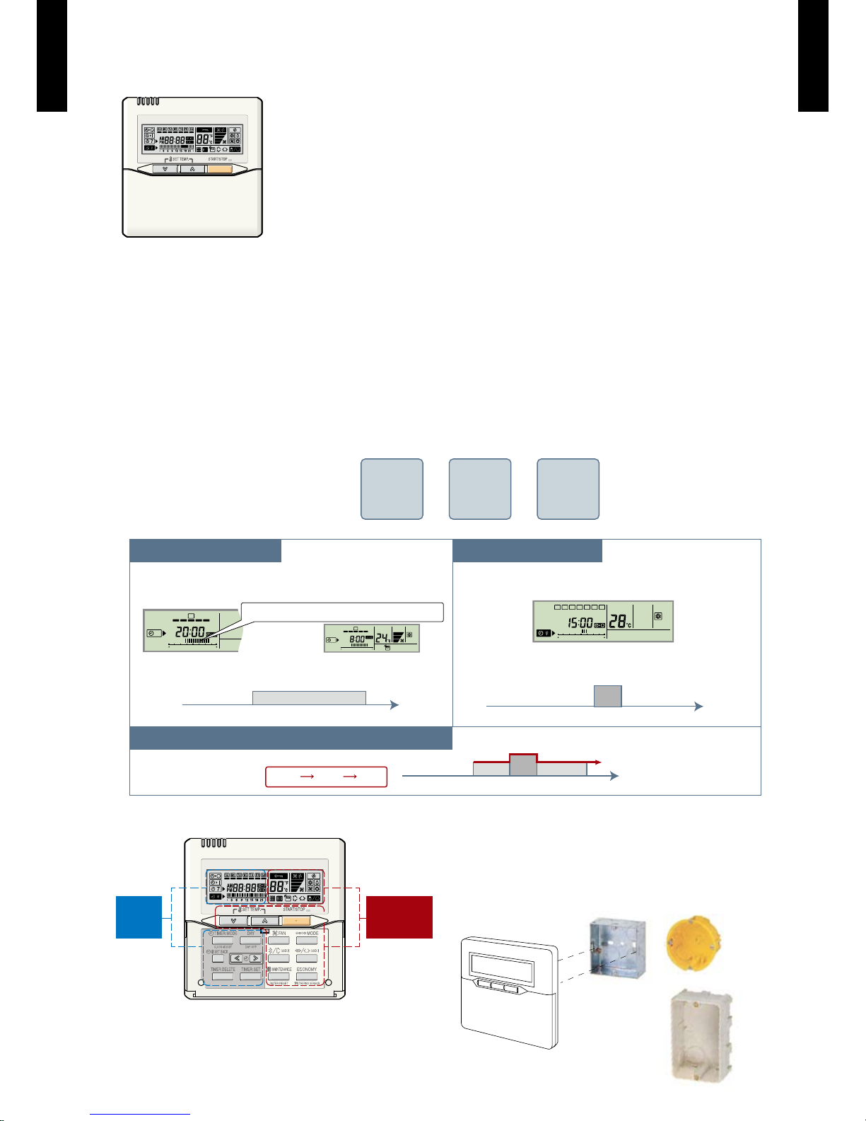
Built-in timers
z
Wired
remote
controller
Weekly
timer
Setback
timer
+ +
Weekly timer Setback timer
At "Weekly timer" + "Set back timer" setup
Easy-to-understand operation
z
[Variable timer control]
The operation/display sections are zoned
according to time and operation, enabling
variable programming to match application.
Simple installation
z
Components are compatible with standard
switch boxes. Flat back construction allows
equipment to be installed wherever it is
needed.
SUMOTUWETH FR SA
7
3126 9
15 18 21
SUMOTUWETH FR SA
7
3126 9
15 18 21
SUMOTUWETH FR SA
3126 9
15 18 21
Possible to set ON/OFF time to operate twice each day
of the week.
Setup scr een example
(Set to Wednes day: 8:00 to 20:00.)
Screen
after setup
European
switch box
JIS box
Setup scr een example
(Set from Sunday to Saturday: 12:00 to 15:0 0, 28 °C.)
Possible to set temperature for two time spans and
for each day of the week.
Easy-to-understand time bar display
24°C
0 3 6 9 12 15 18 21 Time
28°C
0 3 6 9 12 15 18 21 Time
28°C
24°C
0 3 6 9 12 15 18 21 Time
24°C 28°C 24°C
Timer
area
Operation
area
Page 9
- (01 - 06) -
DUCT TYPE
AR
C45-54LC
DUCT TYPE
AR
C45-54LC
FUNCTIONS
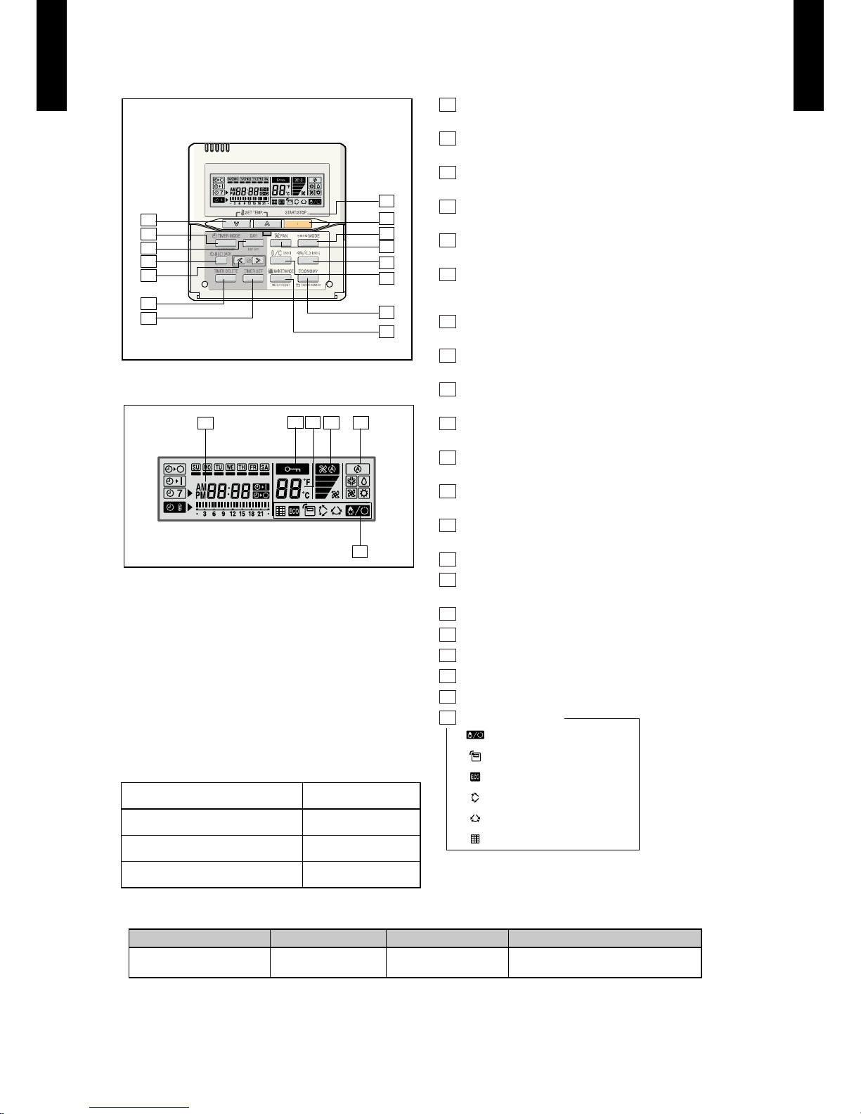
Display panel
SPECIFICATION
WIRING SPECIFICATIONS
Use Size Wire type Remarks
Remote controller
cable
0.33mm
2
22AWG
Use sheathed PVC cable polar
3 core
15
11
10
9
8
2
1
3
5
14
4
12
13
6
7
17
16
18
19
20
21
SIZE (H x W x D mm) 120 x 120 x 18
WEIGHT ( g ) 160
CABLE LENGTH ( m ) 10
POWER ( V ) 12
1
START/STOP button
Pressed to start and stop operation.
2
SET TEMP. button
Selects the setting temperature.
3
MODE button
Selects the operating mode (AUTO, HEAT, FAN, COOL, DRY).
4
FAN button
Selects the fan speed (AUTO, LOW, MED, HIGH).
5
ECONOMY button
Turns the economy efcient mode on and off.
6
TIMER MODE (CLOCK ADJUST) button
Selects the timer mode (OFF TIMER, ON TIMER, WEEKLY
TIMER). Set the current time.
7
DAY (DAY OFF) button
Temporarily cancels of one day timer.
8
SET BACK button
Pressed to select the set back timer.
9
Set time button
Pressed to set time.
10
TIMER DELETE button
The schedule of a weekly timer is deleted.
11
TIMER SET button
Sets the date, hour, minute and on-off time.
12
Vertical airow direction and swing button
Push for two seconds to change the swing mode.
13
Horizontal airow direction and swing button
Push for two seconds to change the swing mode.
14
FILTER RESET button
15
Operation lamp
Lights during operation and when the timer is on.
16
Timer and clock display
17
Operation mode display
18
Fan speed display
19
Operation lock display
20
Temperature display
21
Function display
Defrost display
Thermo sensor display
Economy display
Vertical swing display
Horizontal swing display
Filter display
Functions will be different due to type of indoor unit.
For details, please see operation manual.
Page 10
- (01 - 07) -
DUCT TYPE
AR
C45-54LC
DUCT TYPE
AR
C45-54LC
SYSTEM DIAGRAM
1 remote controller
z
z
2 remote controllers
Master Slave
A B C
Indoor unit Indoor unit
Remote controller Remote controllers
A , B , C : Remote controller cable.
A
<
=
500m ; B+C
<
=
500m
ELECTRICAL WIRING
1 remote controller
z
z
2 remote controllers
Indoor unit
REMOTE
CONTROLLER
1 2 3
1 2 3
Master
Slave
Indoor unit
1 2 3
1 2 3 1 2 3
REMOTE
CONTROLLER
Remote controller Remote controllers
1 (RED) : 12V
2 (WHITE) : Signal
3 (BLACK) : COM
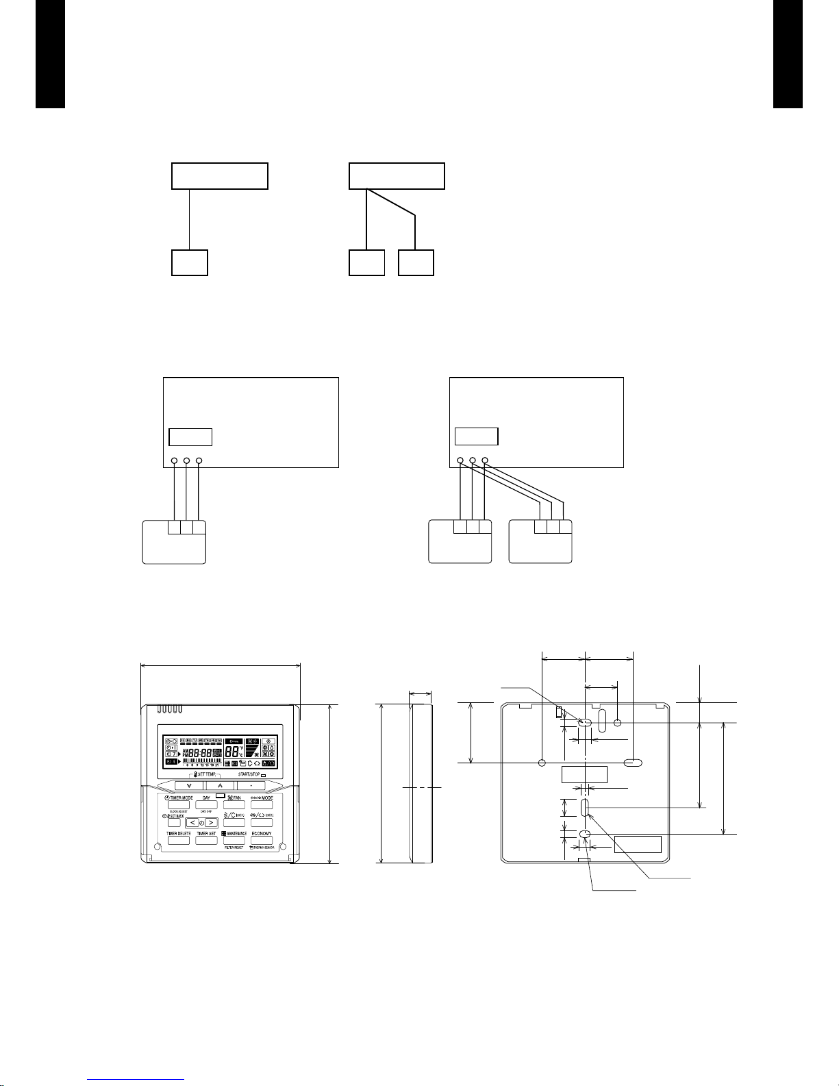
DIMENSIONS
83.5
15.3
63.5
Hole
45.3
4.54.5
4.5
9
12.5
Hole x 2
Hole x 3
6
30 33.5
23
120
120
(120)
18
Front View Side View Rear View
[Unit : mm]
Page 11
- (01 - 08) -
DUCT TYPE
AR
C45-54LC
DUCT TYPE
AR
C45-54LC
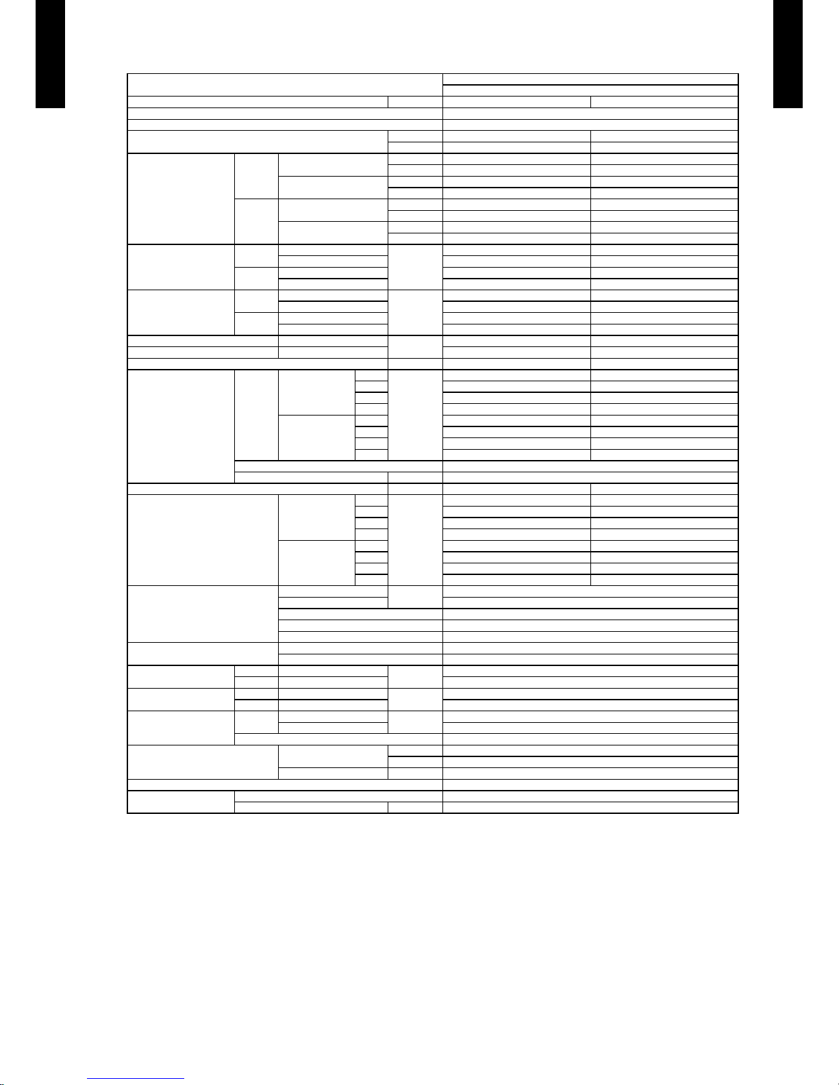
SPECIFICATIONS3.
Note :
Speci cations are base d on the foll owing conditio ns.
Coolin g : Indoor te mperat ure of 27 °CD B / 19 °CWB.an d outdoo r tempera ture of 35 °C DB/24 °C WB.
Heating : I ndoor te mperatu re of 20 °CD B / 15 °CWB.an d outdoor t emperat ure of 7 °CD B/6 °CWB .
Standa rd static p ressur e : 100Pa.
Pipe leng th : 5 m, Heig ht diffe rence : 0 m.(O utdoor un it - Indoo r unit)
Sound pre ssure leve l : Instal l a 2m duct to th e outlet po rt and a 1m duc t to the suction por t and measure.
The maxi mum curr ent is the m aximum va lue when op erated within the o perati on range(t emperat ure)
*: The maxi mum curr ent is the to tal cur rent of indo or unit an d outdoor u nit.
Typ e
DUCTED M ODEL
INVER TER HEATPU MP
Model na me Indoor u nit ARC45 LCTU ARC54LC TU
Power source 230V~ 50 Hz
Availabl e voltag e range 198-2 64V~ 50 Hz
Europea n energy l abel
Cooling C C
Heating A B
Capacity
Cooling
Rated
kW 12.5 13.4
BTU/h 42700 4 5700
Min-Max
kW 4.5-14.0 5.0 -14.5
BTU/h 1540 0-478 00 17100-49500
Heating
Rated
kW 14.0 16.0
BTU/h 4780 0 54600
Min-Max
kW 5.0 -16.2 5. 5-18. 0
BTU/h 17100-55300 18800-61500
Input pow er
Cooling
Rated
kW
4.30 4.77
Max 5.1 5 5.4 0
Heating
Rated 3.80 4.69
Max 5.1 5 5.4 0
Current
Cooling
Rated
A
18.9 20.9
Max* 22.5 23.5
Heating
Rated 16.7 20.5
Max* 22.5 23.5
EER Cooling
kW/kW
2.91 2. 81
COP Heati ng 3.68 3.41
Moistu re remova l l/h (pin ts/h) 1.5 (2.6) 2.0 (3.5)
Fan
Airow
rate
Cooling
High
m
3
/h
3350 3350
Med 2850 2850
Low 243 0 2430
QUIET - -
Heating
High 3350 3350
Med 2850 2850
Low 243 0 2430
QUIET - Type × Q'ty Siroc co × 2
Motor ou tput W 490
Recomm ended st atic pr essure Pa 100 to 250 100 to 250
Sound pr essure l evel
Cooling
High
dB(A)
47 47
Med 43 43
Low 40 40
Quiet - -
Heating
High 47 47
Med 43 43
Low 40 40
Quiet - -
Heat excha nger ty pe
Dimens ions (H × W × D)
mm
336 × 89 0 × 53.2
Fin pitch 1.3
Rows x Sta ges 4 × 16
Pipe ty pe Copper
Fin type Aluminium
Enclos ure (Pane l)
Material Steel
Colour -
Dimensions
( H×W×D)
Net Unit
mm
400 × 105 0 × 500
Gross Unit 460 × 1230 × 6 40
Weight
Net Unit
kg(lbs.)
46 (101)
Gross Unit 51 (112)
Connec tion pi pe
Size
Liquid
mm
Ø9.52 (3/ 8 in.)
Gas Ø15.88 (5/8 i n.)
Method Flare
Operat ion ran ge
Cooling
°C 18 to 32
%RH 80 or les s
Heating °C 16 to 30
Remote co ntroll er typ e Wired
Drain pi pe
Material Steel
Size mm Outer diamete r : 25.4 / Inn er diame ter : 23.4
Page 12
- (01 - 09) -
DUCT TYPE
AR
C45-54LC
DUCT TYPE
AR
C45-54LC
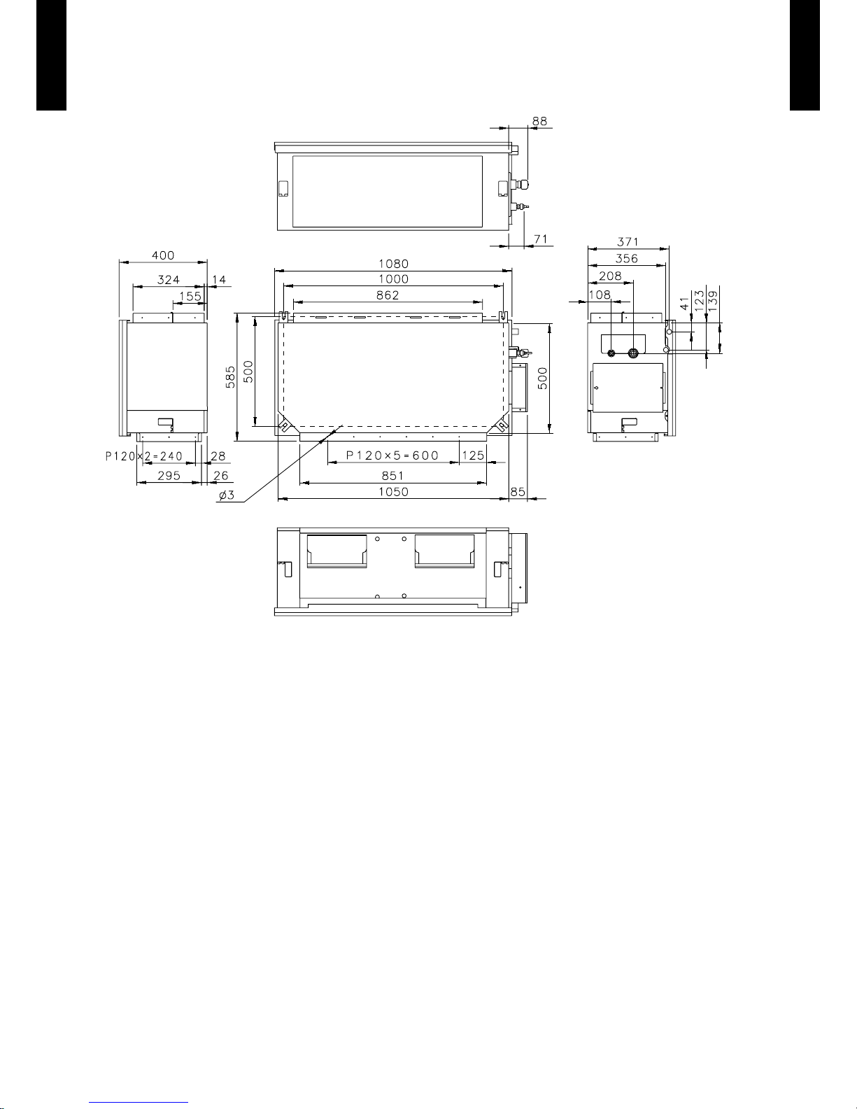
DIMENSIONS4.
MODEL : ARC45LC, ARC54LC
(Unit : mm)
Front view
Top view
Side view (L)
Side view (R)
Rear view
Page 13
- (01 - 10) -
DUCT TYPE
AR
C45-54LC
DUCT TYPE
AR
C45-54LC
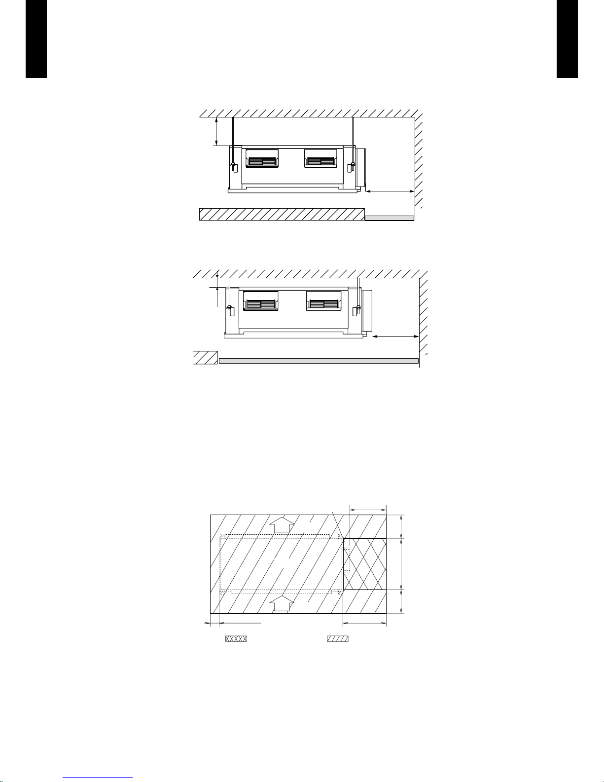
INSTALLATION PLACE
AR
z
C45LC, ARC54LC
Installation by which service space is made on top of the unit (recommended).
350 or
more
450 or more
(Service space)
Service access
Installation by which service is carried out from the bottom of the unit.
20 or
more
450 or more
(Service space)
Service access
MAINTENANCE SPACE
Provide a maintenance space for inspection purposes as shown below.
Do not place any wiring or illumination in the service space, as they will impede service.
: Service access : Service space
Unit
AIR
AIR
Control box
500 or more30 or more
500 or more
450 or more
300
or more
300
or more
AR
z
C45LC, ARC54LC
(Unit : mm)
(Unit : mm)
Page 14
- (01 - 11) -
DUCT TYPE
AR
C45-54LC
DUCT TYPE
AR
C45-54LC
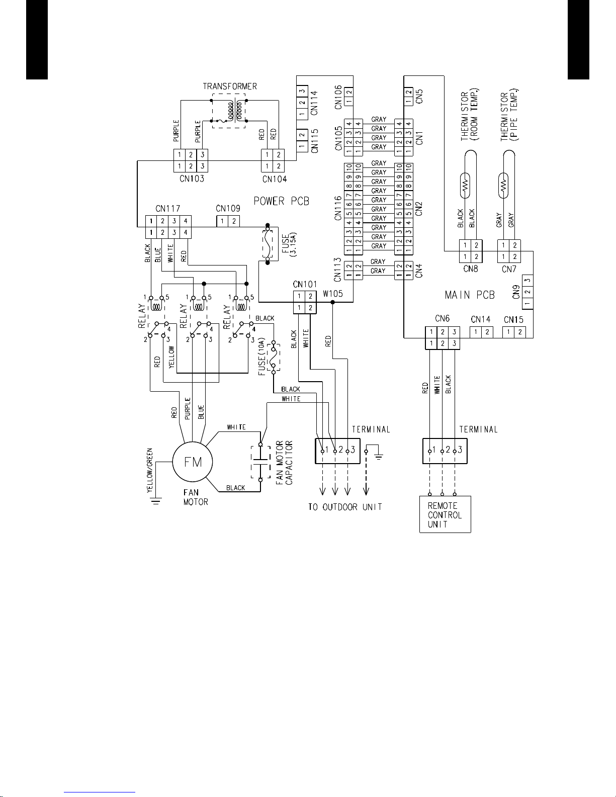
WIRING DIAGRAMS5.
MODEL : ARC45LC, ARC54LC
Page 15
- (01 - 12) -
DUCT TYPE
AR
C45-54LC
DUCT TYPE
AR
C45-54LC
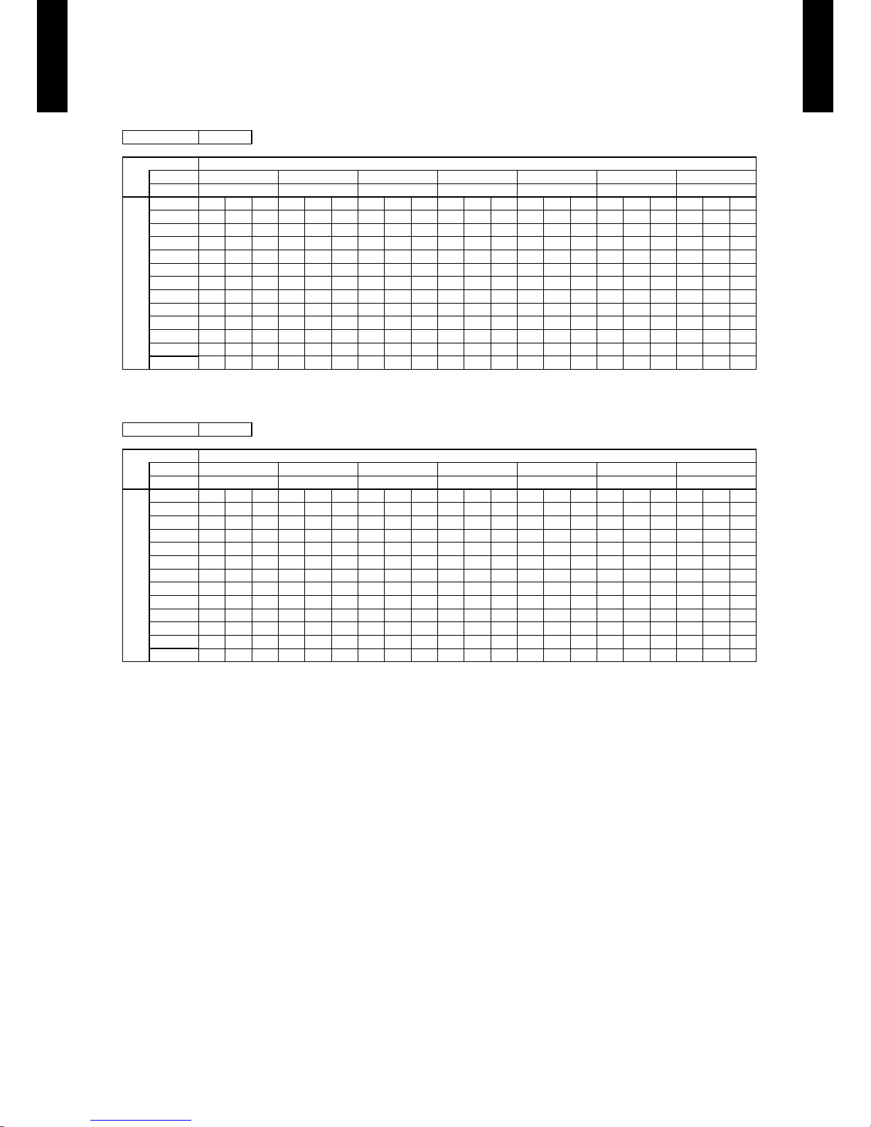
CAPACITY TABLE6.
COOLING CAPACITY6-1.
MODEL : ARC45LC
MODEL : ARC54LC
AFR: Air ow rate (m3/min)
TC : Total capaci ty (kW)
SHC: Sens ible Hea t capaci ty (kW)
IP : Input po wer (kW)
AFR 55.8
Indoor temperature
°CDB 18 21 23 25 27 29 32
°CWB 12 15 16 18 19 21 23
Outdoor temperature
°CDB TC SHC IP TC SHC IP TC SHC IP TC SHC IP TC SHC IP TC SHC IP TC SHC IP
-15 11.75 10.43 2.86 13.09 10.50 2.90 13.54 11.41 2.92 14.43 11.45 2.95 14.88 12.36 2.96 15.77 12.31 2.99 16.66 13.12 3.02
-10 11.74 10.41 2.73 13.08 10.47 2.77 13.53 11.39 2.79 14.42 11.42 2.82 14.86 12.34 2.83 15.76 12.29 2.86 16.65 13.09 2.89
0 12.10 10.59 2.42 13.48 10.65 2.46 13.94 11.58 2.47 14.86 11.62 2.50 15.32 12.54 2.51 16.24 12.49 2.54 17.16 13.31 2.56
5 11.72 10.41 2.55 13.06 10.47 2.59 13.50 11.38 2.60 14.39 11.42 2.63 14.84 12.33 2.64 15.73 12.28 2.67 16.62 13.08 2.69
10 11.56 10.29 2.73 12.87 10.35 2.77 13.31 11.25 2.79 14.19 11.28 2.82 14.63 12.19 2.83 15.51 12.14 2.86 16.38 12.93 2.89
15 11.49 10.23 2.87 12.80 10.29 2.91 13.23 11.19 2.93 14.10 11.22 2.96 14.54 12.12 2.97 15.41 12.07 3.00 16.28 12.86 3.03
20 11.89 10.45 3.38 13.24 10.51 3.43 13.69 11.43 3.45 14.60 11.47 3.48 15.05 12.38 3.50 15.95 12.33 3.54 16.85 13.14 3.57
25 11.49 10.24 3.65 12.80 10.30 3.70 13.24 11.20 3.72 14.11 11.23 3.76 14.55 12.13 3.78 15.42 12.08 3.82 16.30 12.87 3.86
30 11.74 10.41 4.73 13.08 10.48 4.80 13.52 11.39 4.83 14.41 11.43 4.88 14.86 12.34 4.90 15.75 12.29 4.90 16.64 13.09 4.90
35 11.06 9.98 4.97 12.32 10.04 5.05 12.74 10.91 5.07 13.58 10.95 5.12 14.00 11.82 5.15 14.84 11.77 5.15 15.68 12.54 5.15
40 9.68 9.15 4.23 10.78 9.36 4.29 11.15 10.18 4.31 11.88 10.21 4.36 12.25 11.02 4.38 12.98 10.98 4.38 13.72 11.70 4.38
46 7.37 7.36 3.55 8.21 7.81 3.61 8.49 8.46 3.62 9.05 8.52 3.66 9.33 9.20 3.68 9.89 9.16 3.68 10.45 9.76 3.68
AFR 55.8
Indoor temperature
°CDB 18 21 23 25 27 29 32
°CWB 12 15 16 18 19 21 23
Outdoor temperature
°CDB TC SHC IP TC SHC IP TC SHC IP TC SHC IP TC SHC IP TC SHC IP TC SHC IP
-15 12.72 11.08 3.16 14.17 11.14 3.21 14.66 12.12 3.23 15.62 12.15 3.26 16.11 13.13 3.28 17.07 13.07 3.31 18.04 13.93 3.34
-10 12.71 11.05 3.04 14.16 11.12 3.08 14.64 12.09 3.10 15.61 12.13 3.13 16.09 13.10 3.15 17.06 13.05 3.18 18.02 13.90 3.21
0 12.84 11.10 2.73 14.30 11.16 2.77 14.79 12.13 2.79 15.76 12.17 2.82 16.25 13.15 2.83 17.23 13.09 2.86 18.20 13.95 2.89
5 12.44 10.83 2.74 13.85 10.89 2.79 14.33 11.84 2.80 15.27 11.88 2.83 15.74 12.83 2.84 16.69 12.78 2.87 17.63 13.61 2.90
10 12.26 10.69 2.87 13.66 10.75 2.92 14.12 11.69 2.93 15.05 11.73 2.96 15.52 12.66 2.98 16.45 12.61 3.01 17.38 13.44 3.04
15 12.02 10.51 3.17 13.39 10.57 3.22 13.85 11.49 3.24 14.76 11.53 3.27 15.22 12.45 3.29 16.13 12.40 3.32 17.05 13.21 3.36
20 12.42 10.75 4.02 13.84 10.81 4.09 14.31 11.75 4.11 15.25 11.79 4.15 15.72 12.74 4.17 16.67 12.68 4.21 17.61 13.51 4.25
25 12.18 10.63 4.60 13.56 10.69 4.67 14.03 11.62 4.70 14.95 11.66 4.75 15.41 12.59 4.77 16.34 12.54 4.82 17.26 13.36 4.87
30 12.35 10.82 4.99 13.75 10.88 5.07 14.22 11.83 5.09 15.16 11.87 5.14 15.63 12.82 5.17 16.57 12.77 5.17 17.51 13.60 5.17
35 11.46 10.21 5.10 12.76 10.27 5.17 13.20 11.17 5.20 14.07 11.20 5.25 14.50 12.10 5.28 15.37 12.05 5.28 16.24 12.84 5.28
40 9.68 9.15 4.23 10.78 9.36 4.29 11.15 10.18 4.31 11.88 10.21 4.36 12.25 11.02 4.38 12.98 10.98 4.38 13.72 11.70 4.38
46 7.37 7.36 3.55 8.21 7.76 3.61 8.49 8.44 3.62 9.05 8.46 3.66 9.33 9.14 3.68 9.89 9.10 3.68 10.45 9.70 3.68
Page 16
- (01 - 13) -
DUCT TYPE
AR
C45-54LC
DUCT TYPE
AR
C45-54LC
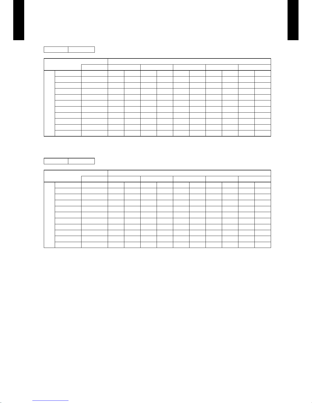
HEATING CAPACITY6-2.
MODEL : ARC45LC
MODEL : ARC54LC
AFR: Air ow rate (
m
3
/min)
TC : Total capaci ty (kW)
IP : Input po wer (kW)
AFR 55.8
Indoor temperature
°CDB 16 18 20 22 24
Outdoor temperature
°CDB °CWB TC IP TC IP TC IP TC IP TC IP
-15 -16 11.47 4.69 11.19 4.79 10.92 4.89 10.65 4.90 10.37 4.90
-10 -11 12.63 4.70 12.33 4.80 12.03 4.90 11.73 4.90 11.43 4.90
-5 -7 13.99 4.70 13.65 4.80 13.32 4.90 12.99 4.90 12.65 4.90
0 -2 15.28 4.70 14.91 4.80 14.55 4.90 14.19 4.90 13.82 4.90
5 3 16.36 4.70 15.97 4.80 15.58 4.90 15.19 4.90 14.80 4.90
7 6 17.01 4.70 16.61 4.80 16.20 4.90 15.80 4.90 15.39 4.90
10 8 18.16 4.70 17.73 4.80 17.30 4.90 16.86 4.90 16.43 4.90
15 10 18.03 4.22 17.60 4.31 17.17 4.40 16.74 4.40 16.31 4.40
20 15 18.59 4.22 18.14 4.31 17.70 4.40 17.26 4.40 16.82 4.40
24 18 18.50 3.81 18.06 3.89 17.62 3.97 17.18 3.97 16.74 3.97
AFR 55.8
Indoor temperature
°CDB 16 18 20 22 24
Outdoor temperature
°CDB °CWB TC IP TC IP TC IP TC IP TC IP
-15 -16 12.10 4.92 11.81 5.03 11.52 5.13 11.23 5.23 10.94 5.28
-10 -11 13.42 5.07 13.10 5.17 12.78 5.28 12.46 5.28 12.14 5.28
-5 -7 15.02 5.07 14.66 5.17 14.30 5.28 13.94 5.28 13.59 5.28
0 -2 16.24 5.07 15.86 5.17 15.47 5.28 15.08 5.28 14.70 5.28
5 3 17.43 5.07 17.02 5.17 16.60 5.28 16.19 5.28 15.77 5.28
7 6 18.90 5.07 18.45 5.17 18.00 5.28 17.55 5.28 17.10 5.28
10 8 19.20 5.07 18.75 5.17 18.29 5.28 17.83 5.28 17.38 5.28
15 10 18.03 4.22 17.60 4.31 17.17 4.40 16.74 4.40 16.31 4.40
20 15 18.59 4.22 18.14 4.31 17.70 4.40 17.26 4.40 16.82 4.40
24 18 18.50 3.81 18.06 3.89 17.62 3.97 17.18 3.97 16.74 3.97
Page 17
- (01 - 14) -
DUCT TYPE
AR
C45-54LC
DUCT TYPE
AR
C45-54LC
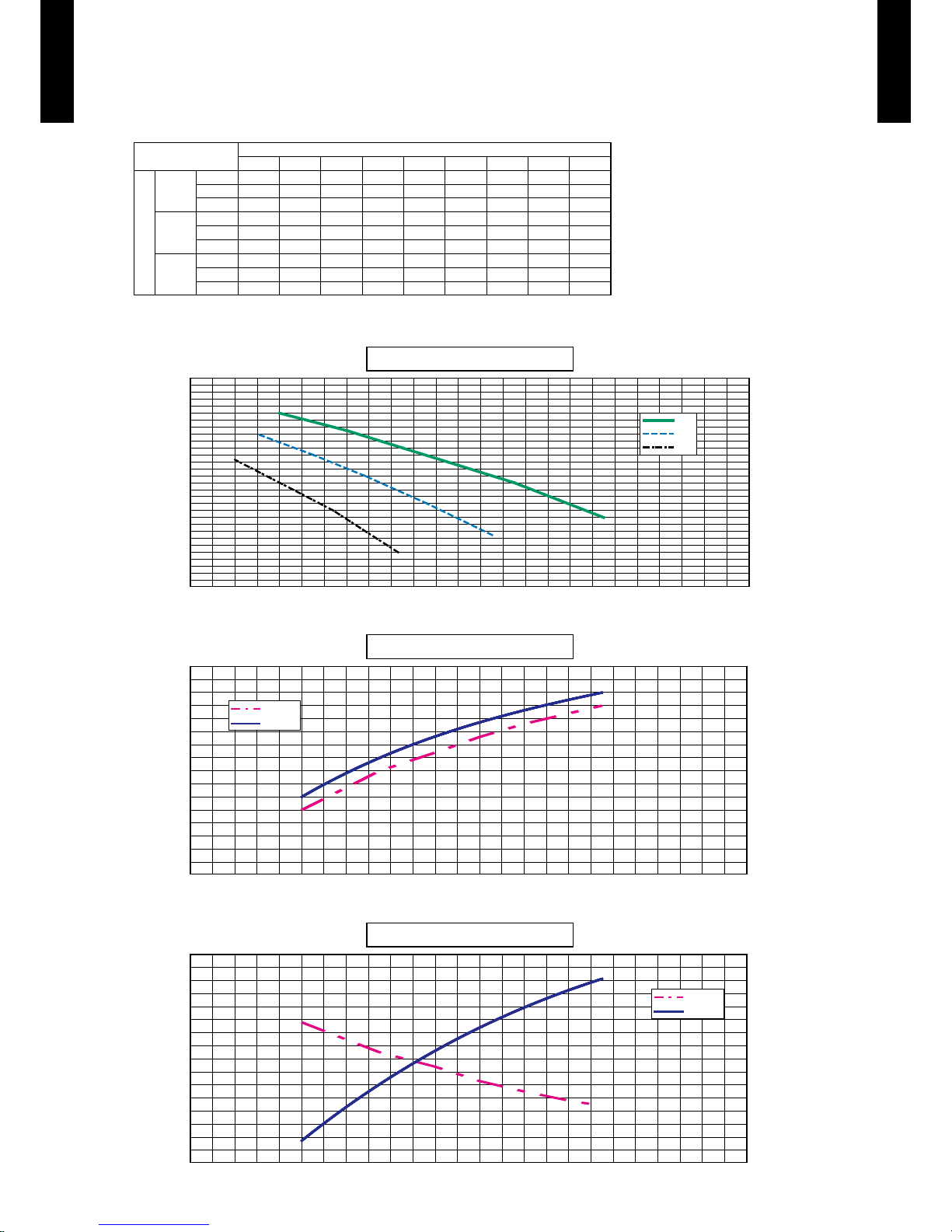
FAN PERFORMANCE AND CAPACITY7.
MODEL : ARC45LC
Static p ressur e (Pa)
50 75 100 125 150 175 200 2 25 250
FAN SPEED
Hi
m
3
/h - - 3350 3150 2950 270 0 24 50 2 280 19 00
l/s - - 931 875 819 750 681 633 528
CFM - - 1972 1854 1736 1589 1442 1342 1118
Med
m
3
/h - 285 0 270 0 252 0 23 50 216 0 1970 1750 -
l/s - 792 750 70 0 6 53 600 547 48 6 -
CFM - 1677 1589 1483 1383 1271 1159 1030 -
Low
m
3
/h 2430 2310 218 0 20 50 19 00 1750 - - -
l/s 675 6 42 6 06 569 528 48 6 - - -
CFM 1430 1360 1283 1207 1118 1030 - - -
Hi
Med
Low
Q-h Characteristic curve
Static pressure(Pa)
300
250
200
150
100
50
0
1,500 2,000 2,500 3,000 3,500 4,000
Air ow (m3/h)
Air temp
Capacity
2,0 0 0
2,3 5 0
2,6 0 0
2,8 0 0
3,0 0 0
3,2 0 0
3,3 5 0
COOLING
capacity(%)
102.0
100.0
98.0
96.0
94.0
92.0
90.0
88.0
86.0
1,500 2,000 2,500 3,000 3,500 4,000
Air ow (m3/h)
Outlet temperature(°C)
18.0
17. 0
16.0
15.0
14.0
13.0
12.0
11. 0
10.0
Air temp
Capacity
HE AT I NG
capacity(%)
102.0
100.0
98.0
96.0
94.0
92.0
90.0
88.0
86.0
1,500 2,000 2,500 3,000 3,500 4,000
Air ow (m3/h)
Outlet temperature(°C)
46.0
44.0
42.0
40.0
38.0
36.0
34.0
32.0
30.0
Page 18
- (01 - 15) -
DUCT TYPE
AR
C45-54LC
DUCT TYPE
AR
C45-54LC
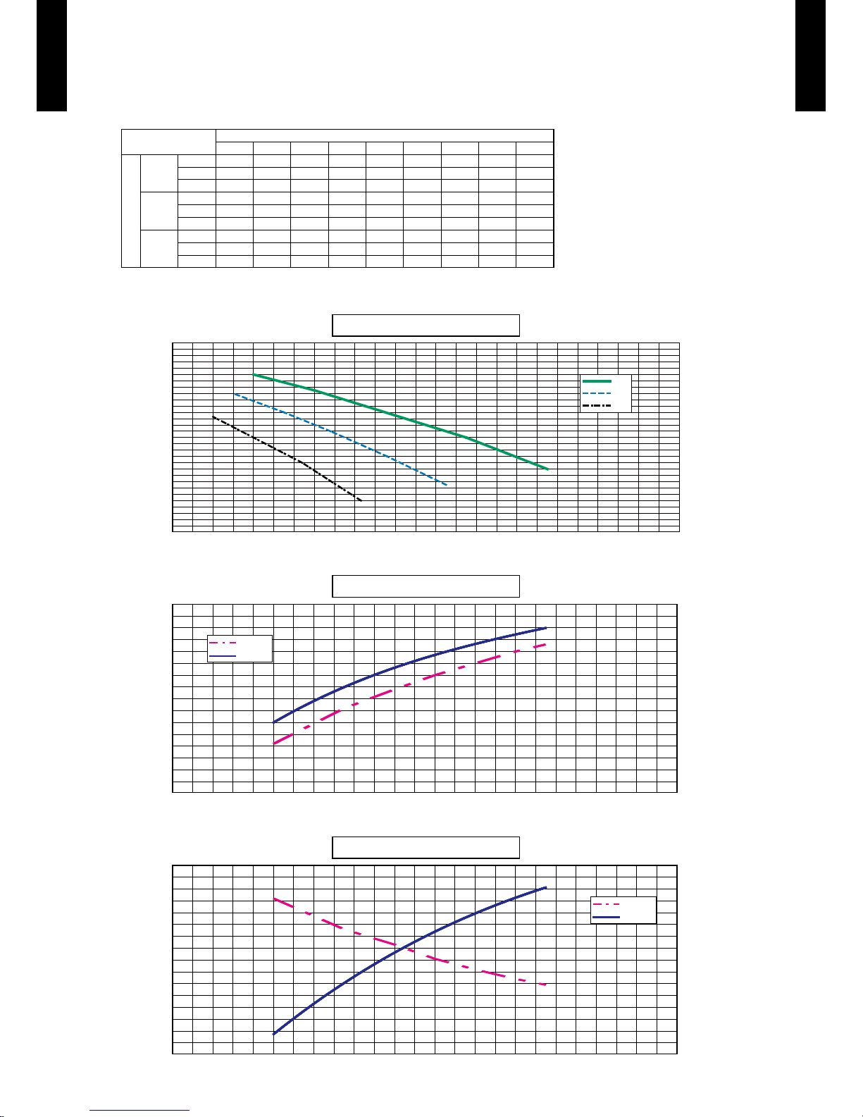
MODEL : ARC54LC
Static p ressur e (Pa)
50 75 100 12 5 150 175 200 2 25 250
FAN SPEED
Hi
m
3
/h - - 3350 3150 2950 270 0 24 50 2 280 19 00
l/s - - 931 875 819 750 681 633 528
CFM - - 1972 1854 1736 1589 1442 1342 1118
Med
m
3
/h - 285 0 270 0 252 0 23 50 216 0 1970 1750 -
l/s - 792 750 70 0 6 53 600 547 48 6 -
CFM - 1677 1589 1483 1383 1271 1159 1030 -
Low
m
3
/h 2430 2310 218 0 20 50 19 00 1750 - - -
l/s 675 6 42 6 06 569 528 48 6 - - -
CFM 1430 1360 1283 1207 1118 1030 - - -
Hi
Med
Low
Q-h Characteristic curve
Static pressure(Pa)
300
250
200
150
100
50
0
1,500 2,000 2,500 3,000 3,500 4,000
Air ow (m3/h)
Air temp
Capacity
2,0 0 0
2,3 5 0
2,6 0 0
2,8 0 0
3,0 0 0
3,2 0 0
3,3 5 0
COOLING
capacity(%)
102.0
100.0
98.0
96.0
94.0
92.0
90.0
88.0
86.0
1,500 2,000 2,500 3,000 3,500 4,000
Air ow (m3/h)
Outlet temperature(°C)
18.0
17. 0
16.0
15.0
14.0
13.0
12.0
11. 0
10.0
Air temp
Capacity
HE AT I NG
capacity(%)
102.0
100.0
98.0
96.0
94.0
92.0
90.0
88.0
86.0
1,500 2,000 2,500 3,000 3,500 4,000
Air ow (m3/h)
Outlet temperature(°C)
46.0
44.0
42.0
40.0
38.0
36.0
34.0
32.0
30.0
Page 19

- (01 - 16) -
DUCT TYPE
AR
C45-54LC
DUCT TYPE
AR
C45-54LC
OPERATION NOISE8.
NOISE LEVEL CURVE8-1.
MODEL : ARC45LC
Condition
Static pressure : 10 0Pa
HIGH
LOW
Heating
z
Octave ba nd sound p ressur e level, dB:(0 dB= 0.00 02µbar)
80
70
60
50
40
30
20
10
0
NC-65
NC-60
NC-55
NC-50
NC-45
NC-40
NC-35
NC-30
NC-25
NC-20
NC -15
HIGH
LOW
Cooling
z
Octave ba nd sound p ressur e level, dB:(0 dB= 0.00 02µbar)
Octave ba nd cente r frequency,Hz
80
70
60
50
40
30
20
10
0
NC-65
NC-60
NC-55
NC-50
NC-45
NC-40
NC-35
NC-30
NC-25
NC-20
NC -15
HIGH
LOW
Octave ba nd sound p ressur e level, dB:(0 dB= 0.00 02µbar)
80
70
60
50
40
30
20
10
0
NC-65
NC-60
NC-55
NC-50
NC-45
NC-40
NC-35
NC-30
NC-25
NC-20
NC -15
HIGH
LOW
Heating
z
Octave ba nd sound p ressur e level, dB:(0 dB= 0.00 02µbar)
80
70
60
50
40
30
20
10
0
NC-65
NC-60
NC-55
NC-50
NC-45
NC-40
NC-35
NC-30
NC-25
NC-20
NC -15
MODEL : ARC54LC
Cooling
z
Octave ba nd cente r frequency,Hz
63 125 250 500 1,00 0 2,0 00 4, 000 8 ,000
Octave ba nd cente r frequency,Hz
63 125 250 500 1,00 0 2,0 00 4, 000 8 ,000
Octave ba nd cente r frequency,Hz
63 125 250 500 1,00 0 2,0 00 4, 000 8 ,000
63 125 250 500 1,00 0 2,0 00 4, 000 8 ,000
Page 20

- (01 - 17) -
DUCT TYPE
AR
C45-54LC
DUCT TYPE
AR
C45-54LC
SOUND LEVEL CHECK POINT8-2.
enohporciM
Measuring ductMeasuring duct
Set the static pressure
as rating in this area
AIR
2 m
1.5 m
1 m
enohporciM
Page 21

- (01 - 18) -
DUCT TYPE
AR
C45-54LC
DUCT TYPE
AR
C45-54LC
ELECTRIC CHARACTERISTICS9.
Model name
ARC45LC
ARC54LC
Power supply
Voltage V 230~
Frequency Hz 50
Max Operating Current A 4.0
Wiring spec.
Connection cable mm
2
1.5-2.5
Limited wiring length m 50
Page 22

- (01 - 19) -
DUCT TYPE
AR
C45-54LC
DUCT TYPE
AR
C45-54LC
SAFETY DEVICES10.
Protection form
Model
ARC45LC
ARC54LC
Circuit protection Current fuse (PCB) 3.15A 250V
Fan motor protection Thermal protector 145±5
°C
OFF
Page 23

- (01 - 20) -
DUCT TYPE
AR
C45-54LC
DUCT TYPE
AR
C45-54LC
EXTERNAL INPUT & OUTPUT11.
PREPARATION
Before connecting the external input in the gure above, preparation is necessary using the signal
wire in the gure below.
When the external input/output is used, connect the external signal wire as shown in the gure.
CN106
(Black)
Indoor
power PC borad
CN5
(Black)
Indoor
control PC board
INPUT OUTPUT Connector
CONTROL INPUT — CN114
Power PC board
— OPERATION STATUS C N115
— FRESH AIR CONTROL CN14
Control PC board
—
AUXILIARY HEATER
CN15
Page 24

- (01 - 21) -
DUCT TYPE
AR
C45-54LC
DUCT TYPE
AR
C45-54LC
EXTERNAL INPUT11-1.
CONTROL INPUT (Operation/Stop)
The air conditioner can be remotely operated by means of the following on-site work.
Operation is started at the following contents by adding the contact input of a commercial ON/OFF
switch to a connector on the external control PC board and turning it ON.
Initial starting after power turned on Starting other than at the left
Operation mode Auto changeover Mode at previous operation
Set temperature 24°C Temperature at previous operation
Air ow mode AUTO Mode at previous operation
Circuit diagram example
z
Indoor
control PC board
Connector
1
2
3
Signal
Field supply
* Make the distance from the PC board to the connected unit within 10 m.
Contact capacity : 5VDC or more, 15mA or more.
Please use the non-polar relays and switches.
Surely insulate with
insulation tape etc. since
this wire is not used.
*10 m
Connected unit
Ex.) Switch
When function setting is "Operation/Stop" mode •
Operation
Stop
ON
OFF
Input signal
Indoor unit
Parts (Optional)
z
Model name
UTD-ECS5A
Wire (External input)
Page 25

- (01 - 22) -
DUCT TYPE
AR
C45-54LC
DUCT TYPE
AR
C45-54LC
EXTERNAL OUTPUT11-2.
OPERATION STATUS OUTPUT
An air conditioner operation status signal can be output.
Circuit diagram example
z
Field supply
Ex.)Display
Indoor
control PC board
Connected unit
Ex.)Relay unit
1
2
Signal
Relay
power
supply
V
Connector
* Make the distance from the PC board to the connected unit within 10m.
Relay spec. : Max.24VDC, 10mA to less than 500mA.
*10 m
24V DC
ON
OFF
Operation
Stop
Indoor unit
Output signal
Parts (Optional)
z
Model name
UTD-ECS5A
Wire (External output)
Page 26

- (01 - 23) -
DUCT TYPE
AR
C45-54LC
DUCT TYPE
AR
C45-54LC
FRESH AIR CONTROL OUTPUT
A signal linked to air conditioner indoor fan ON can be output.
* However, signal becomes OFF during cold air prevention control operation.
Circuit diagram example
z
Field supply
Indoor
control PC board
Connector
1
12 V
on/off
2
Signal
Relay
power
supply
* Make the distance from the PC board to the connected unit within 10m.
Relay spec. : Rated 12VDC, 50mA or less.
Ex.) Fan
Connected unit
Ex.) Relay unit
*10 m
ON
OFF
Operation
Stop
Indoor fan
Output signal
Parts (Optional)
z
Model name
UTD-ECS5A
Wire (Fresh air output)
Page 27

- (01 - 24) -
DUCT TYPE
AR
C45-54LC
DUCT TYPE
AR
C45-54LC
AUXILIARY HEATER OUTPUT
A signal is outputed from Connector when indoor fan and compressor turn on under heating
operation.
* Signal output performance specications are as
shown on the right.
Ex. When Set Temperature(Ts) is 22°C
and Room Temperature(Tr) increase above 12°C, •
signal output is on.
and Room Temperature(Tr) increase above 21°C, •
signal output is off.
and Room Temperature(Tr) decrease below 19°C, signal output is on. •
and Room Temperature(Tr) decrease below 10°C, signal output is off. •
Jumper wire (Indoor Unit)
z
This is used to continue indoor unit fan operation for 1 minute after thermo OFF in heating mode.
1 minute delay control set by cutting jumper wire on PCB.
Circuit diagram example
z
Field supply
Indoor
control PC board
Connector
1
12 V
on/off
2
Signal
Relay
power
supply
* Make the distance from the PC board to the connected unit within 10m.
Relay spec. : Rated 12VDC, 50mA or less.
Ex.) Heater
Connected unit
Ex.) Relay unit
*10 m
ON
OFF
Operation
Stop
Heating
operation
Indoor unit fan
ON
OFF
Output signal
1min
!
CAUTION
Please locate external a heater between the indoor unit and the ductwork.
Please be sure to use delay control of a fan.
OFF
OFF
ON
Tr-Ts
Tr-Ts = -3°C
Tr-Ts = -12°C
Tr-Ts = -1°C
Tr-Ts = -10°C
Exter nal
Heater
Supply air Return air
Indooruni t
Page 28

- (01 - 25) -
DUCT TYPE
AR
C45-54LC
DUCT TYPE
AR
C45-54LC
Parts (Optional)
z
Model name
UTD-ECS5A
Wire (Heater output)
Page 29

- (01 - 26) -
DUCT TYPE
AR
C45-54LC
DUCT TYPE
AR
C45-54LC
FUNCTION SETTING12.
INDOOR UNIT12-1.
SWITCH POSITION
Control PC board
SW1 SW2
SW3
CN14
CN15
JM1
JM2
JM3
ON
1 2 3 1 2 34
OFF
ON
OFF
SW1 SW2
INDOOR UNIT
DIP SW
SW 1
1
Forbidden
2
3
4
SW 2
1
2
3
Rotary SW SW 3 Indoor unit address setting
Jumper Wire
JM 1
Forbidden
JM 2
JM 3 Fan delay setting
Page 30

- (01 - 27) -
DUCT TYPE
AR
C45-54LC
DUCT TYPE
AR
C45-54LC
ROTARY SWITCH SETTING
Indoor unit address setting (SW3)
z
This switch can be used when group control system. Set the indoor unit address in the 1,2,-,15
orde r.
(. . .Factory setting)
SW 3 SW state
0 single
1-15 Indoor unit address
JUMPER WIRE SETTING
JM1, 2 setting forbidden
z
Fan delay setting (JM3)
z
When the indoor unit is stopped while operating in conjunction with auxiliary heater, the indoor unit
fan operation will continue for one minute.
(. . .Factory setting)
JM state
Connect Invalid
Disconnect Valid
Page 31

- (01 - 28) -
DUCT TYPE
AR
C45-54LC
DUCT TYPE
AR
C45-54LC
• The function settings of the control of the indoor unit can be changed by this procedure according to the installation conditions.
Incorrect settings can cause the indoor unit malfunction.
• After the power is turned on, perform the “FUNCTION SETTING” according to the installation conditions using the remote
controller.
• The settings may be selected between the following two: Function Number or Setting Value.
• Settings will not be changed if invalid numbers or setting values are selected.
PREPARATION
Turn on the power.
z
* By turning on the power indoor units, so make sure the piping air-tight test and vacuuming
havebeen conducted before turning on the power.
* Also check again to make sure no wiring mistakes were made before turning on the power.
FUNCTION SETTING METHOD (for Wired remote controller)
Setting method
z
(1) Press the set temperature buttons ( ) ( ) and fan control button simultaneously for more than 5 seconds to enter the function
setting mode.
SU
MO
TU
WE
TH FR
SA
(2) Press the SET BACK button to select the indoor unit number.
SET BACK
SUMOTUWETH FR
SA
Unit number of INDOOR UNIT
3) Press the set time buttons to select the function number.
Function number
SUMOTUWETH FR
SA
(4) Press the set temperature buttons ( ) ( ) to select the setting value. The display ashes as shown to the right during setting value
selection.
INDOOR UNIT (Setting by remote controller)12-2.
Page 32

- (01 - 29) -
DUCT TYPE
AR
C45-54LC
DUCT TYPE
AR
C45-54LC
(5) Press the TIMER SET button to conrm the setting. Press the TIMER SET button for a few seconds until the setting value stops
ashing. If the setting value display changes or if “- -” is displayed when the ashing stops, the setting value has not been set correctly.
(An invalid setting value may have been selected for the indoor unit.)
Settin g value
SUMOTUWETH FR
SA
(6) Repeat steps 2 to 5 to perform additional settings. Press the set temperature buttons ( ) ( ) and fan control button simultaneously
again for more than 5 seconds to cancel the function setting mode. In addition, the function setting mode will be automatically canceled
after 1 minute if no operation is per formed.
(7) After completing the FUNCTION SETTING, be sure to turn of f the power and turn it on again.
!
CAUTION
• After turning off the power, wait 30 seconds or more before turning on it again. The FUNCTION SET TING doesn’t become
effective if it doesn’t do so.
CONTENTS FUNCTION SETTING
1. Room temperature control for cooling
• Depending on the installed environment, correction of the room temperature sensor may be required.
Select the appropriate control setting according to the installed environment.
(. . .Factory setting)
Setting description Function number Setting value
Standard
30
00
Slightly lower control 01
Higher control 02
Lower control 03
2. Room temperature control for heating
• Depending on the installed environment, correction of the room temperature sensor may be required.
Select the appropriate control setting according to the installed environment.
(. . .Factory setting)
Setting description Function number Setting value
Standard
31
00
Lower control 01
Slightly higher control 02
Higher control 03
3. Auto restart
• Enable or disable automatic restart after a power
(. . .Factory setting)
Setting description Function number Setting value
Enable
40
00
Disable 01
• Auto restar t is an emergency function such as for power outage etc. Do not attempt to use this function in normal operation.
Be sure to operate the unit by remote controller or external device.
4.Room temperature sensor switching
• (Only for wired remote controller)
When using the Wired remote controller temperature sensor, change the setting to "Both" (01)..
(. . .Factory setting)
Setting description Function number Setting value
Indoor unit
42
00
Both 01
00: Sensor on the indoor unit is active.
01: Sensors on both indoor unit and wired remote controller are active.
*Remote controller sensor must be turned on by using the remote controller.
Page 33

- (01 - 30) -
DUCT TYPE
AR
C45-54LC
DUCT TYPE
AR
C45-54LC
(
5.Room temperature sensor switching (Aux.)
• To use the temperature sensor on the wired remote controller only, change the setting to " Wired remote controller" (01). This function
will only work if the function setting 42 is set at "Both" (01)
(. . .Factory setting)
Setting description Function number Setting value
Both
48
00
Wired remote controller 01
Page 34

- (01 - 31) -
DUCT TYPE
AR
C45-54LC
DUCT TYPE
AR
C45-54LC
WIRED REMOTE CONTROLLER12-3.
SWITCH POSITION
DIP SWITCH SETTING
Dual remote controller setting
z
Set the remote controller DIP switch No.2 according to the following table.
Memory backup setting
z
Set to ON to use batteries for the memory backup. If batteries are not used, all of the settings
stored in memory will be deleted if there is a power failure.
DIP SW
1 Can not be used. (Do not change)
2 Dual remote controller setting
3 Can not be used. (Do not change)
4 Can not be used. (Do not change)
5 Can not be used. (Do not change)
6 Memory backup setting
ON
ON
OFF
1
2
3
4
5
6
Front case (back side)
Do not use this
DIP Switch
DIP Switch
(
Factory setting)
Number
of remote
controller
Master unit Slave unit
DIP-SW No.2 DIP-SW No.2
1 (Normal) OFF ―
2 (Dual) OFF ON
(
Factory setting)
DIP-SW
No.6
Memory backup
OFF Invalidity
ON Validity
Page 35

- (01 - 32) -
DUCT TYPE
AR
C45-54LC
DUCT TYPE
AR
C45-54LC
OPTIONAL PARTS13.
Exterior Parts name Model No. Summary
Wired remote
controller
UTB-UD
Unit control is performed by wired
remote controller.
Wired remote controller is
attached in one as accessories.
Wired remote controller is two
installation possibility in one
indoor unit.
Simple remote
controller
UTB-PB
Remote
sensor
UT Y-XS Z X
New amenity space can be
offered by installing the Remote
sensor in the remote controller.
Long-life lter UTD-LF60KA
Long- life lter can be mounted to
the indoor unit.
( x 1 ) ( x 2 )
( x 1 ) ( x 2 )
External
control set
UTD-ECS5A
Use to connect with various
peripheral devices and air
conditioner PC board.
(Set of 6)
Page 36

DTR_AO081E_02
2013.11.08
SINGLE TYPE :
AOA45LCTL
AOA54LCTL
2. OUTDOOR UNIT
Page 37

OUTDOOR UNIT
AO
A45-54LC
OUTDOOR UNIT
AO
A45-54LC
2. OUTDOOR UNIT
CONTENTS
1. SPECIFICATIONS
······························································································ 02 - 01
2. DIMENSIONS
········································································································ 02 - 02
3. INSTALLATION PLACE
················································································ 02 - 03
3-1. SINGLE OUTDOOR UNIT INSTALLATION
················································· 02 - 03
3-2. MULTIPLE OUTDOOR UNIT INSTALLATION
············································ 02 - 04
3-3. OUTDOOR UNIT INSTALLATION IN MULTI ROW
··································· 02 - 04
4. REFRIGERANT CIRCUIT
············································································ 02 - 05
5. WIRING DIAGRAMS
······················································································· 02 - 06
6. CAPACITY COMPENSATION RATE FOR PIPE LENGTH AND
HEIGHT DIFFERENCE
···························································································· 02 - 07
7. ADDITIONAL CHARGE CALCULATION
········································ 02 - 09
8. AIR FLOW
················································································································ 02 - 10
9. OPERATION NOISE
·························································································02 - 11
9-1. NOISE LEVEL CURVE
························································································02 - 11
9-2. SOUND LEVEL CHECK POINT
········································································02 - 12
10. ELECTRIC CHARACTERISTICS
···························································02 - 13
11. SAFETY DEVICES
·····························································································02 - 14
12. EXTERNAL INPUT & OUTPUT
·······························································02 - 15
12-1. EXTERNAL INPUT
································································································02 - 15
12-2. EXTERNAL OUTPUT
···························································································02 - 17
13. FUNCTION SETTING
······················································································ 02 - 19
13-1. FIELD SETTING SWITCHES
············································································ 02 - 19
13-2. SETTING METHOD
····························································································· 02 - 20
13-2-1. LOW NOISE MODE ······················································································· 02 - 20
13-2-2. PEAK CUT MODE ························································································· 02 - 21
14. OPTIONAL PARTS
··························································································· 02 - 22
Page 38

- (02 - 01) -
OUTDOOR UNIT
AO
A45-54LC
OUTDOOR UNIT
AO
A45-54LC
SPECIFICATIONS1.
Note :
Speci cations are base d on the foll owing conditio ns.
Coolin g : Indoor te mperat ure of 27 °CD B / 19 °CWB.an d outdoo r tempera ture of 35 °C DB/24 °C WB.
Heating : I ndoor te mperatu re of 20 °CD B / 15 °CWB.an d outdoor t emperat ure of 7 °CD B/6 °CWB .
Pipe leng th : 5 m, Heig ht diffe rence : 0 m.(O utdoor un it - Indoo r unit)
Model na me AOA45LCTL AOA54LC TL
Power source 1Ø 230V~ 50 Hz
Available voltage r ange 198-26 4V~ 50H z
Starting cur rent A 18. 9 20.9
Fan
Airow
rate
Cooling
(m
3
/h)
6,750 6,750
Heating 6,200 6,850
Type × Q'ty Propeller × 2
Motor out put W 104 104
Sound pressure level
Cooling
dB(A)
55 55
Heating 55 57
Heat exchanger type
Dimensions (H × W × D)
mm
1260 × 900 × 36.4
Fin pitch 1.30
Rows x Stag es 2 × 60
Pipe typ e Copper
Fin type
Type (Material) Corrugate (Aluminium)
Surfa ce treatment Corrosio n resist ance (Blue n)
Compressor
Type × Q'ty Twin Rotary × 1
Motor out put W 2100
Refrigerant
Typ e R410 A
Charge g 3350
Refrigerant oil Typ e RB68
Enclosu re
Material Steel she et
Colour
BEIGE
( Approximate colour of MU NSELL 10YR 7.5 / 1.0 )
Dimensions
( H×W×D)
Net
mm
1290 × 90 0 × 330
Gross 1430 × 105 0 × 445
Weight
Net
kg(lbs.)
86 (190)
Gross 94 (208)
Connec tion pipe
Size
(Standard)
Liquid
mm
Ø 9.52 (Ø 3/8 in.)
Gas Ø 15.88 (Ø 5/8 in.)
Method Flare
Pre- charge l ength
m
20
Max. length 50
Max. height dif ferenc e 30
Operat ion rang e
Cooling
°C
-15 to 46
Heating -15 to 24
Page 39

- (02 - 02) -
OUTDOOR UNIT
AO
A45-54LC
OUTDOOR UNIT
AO
A45-54LC
DIMENSIONS2.
MODEL : AOA45LC, AOA54LC
(Unit : mm)
45
66
(
370
)
38
(Liquid)
46
(
Gas
)
40
650 11 9132
1290
900
21
9
Ø28
(Cable port)
Pipe port
87
131
25
543
(
Gas valve
)
540
(Liquid valve)
Ø28
(Cable port)
3-way valve
(
Gas
)
3-way valve
(
Liquid
)
Terminal blocks
21
50
330
31
12
Ø28
(Cable port)
21
55
50
156
112
Ø28
(Cable port)
Pipe port
A
188
265
302
400
51.5
440
625
330
31
89
95
120
50
95
167
21
67
Ø28
(Cable port)
Ø28 (Cable port)
Pipe port
Front view
Bottom view
Side view Rear view
Detail A
1446
1654
Pipe & cable port
Top view
Page 40

- (02 - 03) -
OUTDOOR UNIT
AO
A45-54LC
OUTDOOR UNIT
AO
A45-54LC
INSTALLATION PLACE3.
SINGLE OUTDOOR UNIT INSTALLATION3-1.
WHEN THE UPWARD AREA IS OPEN
(Unit : mm)
Obstacles at rear
only
Obstacles at rear and
sides only
Obstacles at front
only
150
200
200
300
1000 or more
Obstacles at front and
rear only
1000 or more
150
WHEN AN OBSTRUCTION IS PRESENT ALSO IN THE UPWARD AREA
(Unit : mm)
Obstacles at rear and
above only
Obstacles at rear, sides, and above only
Max. 500
300
1000
Max. 500
500
250
250
1500
Page 41

- (02 - 04) -
OUTDOOR UNIT
AO
A45-54LC
OUTDOOR UNIT
AO
A45-54LC
MULTIPLE OUTDOOR UNIT INSTALLATION3-2.
WHEN THE UPWARD AREA IS OPEN
(Unit : mm)
Obstacles at rear only Obstacles at front only Obstacles at front and rear
only
300
1500 or more
500
1500 or more
WHEN AN OBSTRUCTION IS PRESENT ALSO IN THE UPWARD AREA
(Unit : mm)
Obstacles at rear and above only
1500
1500
500
Max. 300
OUTDOOR UNIT INSTALLATION IN MULTI ROW3-3.
(Unit : mm)
Single parallel unit arrangement Multiple parallel unit arrangement
1000
2000 or more
600
150
3000 or more
600
1500
500
Page 42

- (02 - 05) -
OUTDOOR UNIT
AO
A45-54LC
OUTDOOR UNIT
AO
A45-54LC
REFRIGERANT CIRCUIT4.
MODEL : AOA45LC, AOA54LC
Page 43

- (02 - 06) -
OUTDOOR UNIT
AO
A45-54LC
OUTDOOR UNIT
AO
A45-54LC
WIRING DIAGRAMS5.
MODEL : AOA45LC, AOA54LC
Page 44

- (02 - 07) -
OUTDOOR UNIT
AO
A45-54LC
OUTDOOR UNIT
AO
A45-54LC
CAPACITY COMPENSATION RATE FOR PIPE LENGTH 6.
AND HEIGHT DIFFERENCE
MODEL : AOA45LC
Height difference H
HH
1 Indoor unit is upper than outdoor unit.
2 Indoor unit is under than outdoor unit.
Outdoor unit
Outdoor unit
Connection pipe
Indoor unit
Indoor unit
Connection pipe
HEATING
Pipe length (m)
5 7. 5 10 20 30 40 50
Height
difference H
(m)
Û
1
Indoor unit is
upper than
outdoor unit.
30 - - - - 0.978 0.968 0.958
20 - - - 0.988 0.978 0.968 0.958
10 - - 0.998 0.988 0.978 0.968 0.958
7. 5 - 1.000 0.998 0.988 0.978 0.968 0.958
5 1.000 1.000 0.998 0.988 0.978 0.968 0.958
0 1.000 1.000 0.998 0.988 0.978 0.968 0.958
Û
2
Indoor unit is
under than
outdoor unit.
-5 0.998 0.995 0.993 0.983 0.973 0.963 0.953
-7. 5 - 0.993 0.991 0.981 0.971 0.961 0.951
-10 - - 0.988 0.978 0.968 0.958 0.948
-20 - - - 0.968 0.958 0.949 0.939
-30 - - - - 0.949 0.939 0.929
COOLING
Pipe length (m)
5 7. 5 10 20 30 40 50
Height
difference H
(m)
Û
1
Indoor unit is
upper than
outdoor unit.
30 - - - - 0.879 0.846 0.814
20 - - - 0.926 0.893 0.861 0.828
10 - - 0.975 0.942 0.908 0.875 0 . 8 41
7. 5 - 0.988 0.979 0.946 0.912 0.878 0.845
5 0.992 0.992 0.983 0.949 0.916 0.882 0.848
0 1.000 1.000 0.991 0.957 0.923 0.889 0.855
Û
2
Indoor unit is
under than
outdoor unit.
-5 1.000 1.000 0.991 0.957 0.923 0.889 0.855
-7. 5 - 1.000 0.991 0.957 0.923 0.889 0.855
-10 - - 0.991 0.957 0.923 0.889 0.855
-20 - - - 0.957 0.923 0.889 0.855
-30 - - - - 0.923 0.889 0.855
Page 45

- (02 - 08) -
OUTDOOR UNIT
AO
A45-54LC
OUTDOOR UNIT
AO
A45-54LC
MODEL : AOA54LC
Height difference H
HH
1 Indoor unit is upper than outdoor unit.
2 Indoor unit is under than outdoor unit.
Outdoor unit
Outdoor unit
Connection pipe
Indoor unit
Indoor unit
Connection pipe
HEATING
Pipe length (m)
5 7. 5 10 20 30 40 50
Height
difference H
(m)
Û
1
Indoor unit is
upper than
outdoor unit.
30 - - - - 0.978 0.968 0.958
20 - - - 0.988 0.978 0.968 0.958
10 - - 0.998 0.988 0.978 0.968 0.958
7. 5 - 1.000 0.998 0.988 0.978 0.968 0.958
5 1.000 1.000 0.998 0.988 0.978 0.968 0.958
0 1.000 1.000 0.998 0.988 0.978 0.968 0.958
Û
2
Indoor unit is
under than
outdoor unit.
-5 0.998 0.995 0.993 0.983 0.973 0.963 0.953
-7. 5 - 0.993 0.991 0.981 0.971 0.961 0.951
-10 - - 0.988 0.978 0.968 0.958 0.948
-20 - - - 0.968 0.958 0.949 0.939
-30 - - - - 0.949 0.939 0.929
COOLING
Pipe length (m)
5 7. 5 10 20 30 40 50
Height
difference H
(m)
Û
1
Indoor unit is
upper than
outdoor unit.
30 - - - - 0.871 0.837 0.803
20 - - - 0.921 0.886 0 .851 0.816
10 - - 0.971 0.936 0.900 0.865 0.830
7. 5 - 0.988 0.975 0.940 0.904 0.868 0.833
5 0.992 0.992 0.979 0.943 0.908 0.872 0.836
0 1.000 1.000 0.987 0. 9 51 0.915 0.879 0.843
Û
2
Indoor unit is
under than
outdoor unit.
-5 1.000 1.000 0.987 0.951 0. 915 0.879 0.843
-7. 5 - 1.000 0.987 0.9 51 0.915 0.879 0.843
-10 - - 0.987 0.951 0.915 0.879 0.843
-20 - - - 0.951 0.915 0.879 0.843
-30 - - - - 0.915 0.879 0.843
Page 46

- (02 - 09) -
OUTDOOR UNIT
AO
A45-54LC
OUTDOOR UNIT
AO
A45-54LC
ADDITIONAL CHARGE CALCULATION7.
MODEL : AOA45LC, AOA54LC
REFRIGERANT CHARGE
z
Refrigerant type R410A
Refrigerant amount g 3,350
Total pipe length m 20 or less 30 40 50 (MAX)
40g/m
Additional charge g 0 400 800 120 0
Page 47

- (02 - 10) -
OUTDOOR UNIT
AO
A45-54LC
OUTDOOR UNIT
AO
A45-54LC
AIR FLOW8.
MODEL : AOA45LC, AOA54LC
Cooling
z
Heating
z
MODEL
Number of
rotations
(r.p.m.)
Air ow
AOA45LC
Upper fan 850
m
3
/h 6750
l/s 1875
Lower fan 800
CFM 3974
AOA54LC
Upper fan 850
m
3
/h 6750
l/s 1875
Lower fan 800
CFM 3974
MODEL
Number of
rotations
(r.p.m.)
Air ow
AOA45LC
Upper fan 780
m
3
/h 6200
l/s 172 2
Lower fan 750
CFM 3650
AOA54LC
Upper fan
850
m3/h
6850
l/s
1903
Lower fan
830
CFM
4033
Page 48

- (02 - 11) -
OUTDOOR UNIT
AO
A45-54LC
OUTDOOR UNIT
AO
A45-54LC
OPERATION NOISE9.
NOISE LEVEL CURVE9-1.
MODEL : AOA45LC
Cooling
z
Octave ba nd sound p ressur e level, dB:(0 dB= 0.00 02µbar)
Octave ba nd cente r frequency,Hz
80
70
60
50
40
30
20
10
0
63 125 250 500 1,00 0 2,0 00 4, 000 8 ,000
NC-65
NC-60
NC-55
NC-50
NC-45
NC-40
NC-35
NC-30
NC-25
NC-20
NC -15
Heating
z
Octave ba nd sound p ressur e level, dB:(0 dB= 0.00 02µbar)
Octave ba nd cente r frequency,Hz
80
70
60
50
40
30
20
10
0
63 125 250 500 1,00 0 2,0 00 4, 000 8 ,000
NC-65
NC-60
NC-55
NC-50
NC-45
NC-40
NC-35
NC-30
NC-25
NC-20
NC -15
Heating
z
Octave ba nd sound p ressur e level, dB:(0 dB= 0.00 02µbar)
Octave ba nd cente r frequency,Hz
80
70
60
50
40
30
20
10
0
63 125 250 500 1,00 0 2,0 00 4, 000 8 ,000
NC-65
NC-60
NC-55
NC-50
NC-45
NC-40
NC-35
NC-30
NC-25
NC-20
NC -15
Octave ba nd sound p ressur e level, dB:(0 dB= 0.00 02µbar)
Octave ba nd cente r frequency,Hz
80
70
60
50
40
30
20
10
0
63 125 250 500 1,00 0 2,0 00 4, 000 8 ,000
MODEL : AOA54LC
Cooling
z
NC-65
NC-60
NC-55
NC-50
NC-45
NC-40
NC-35
NC-30
NC-25
NC-20
NC -15
Page 49

- (02 - 12) -
OUTDOOR UNIT
AO
A45-54LC
OUTDOOR UNIT
AO
A45-54LC
SOUND LEVEL CHECK POINT9-2.
Microphone
1m
Microphone
Air Flow
Page 50

- (02 - 13) -
OUTDOOR UNIT
AO
A45-54LC
OUTDOOR UNIT
AO
A45-54LC
ELECTRIC CHARACTERISTICS10.
Model name AOA45LC AOA54LC
Power supply
Voltage V 230 ~
Frequency Hz 50
*1) Max. operating current A 22.5 23.5
*2) Wiring spec.
Circuit breaker current A 30
Power cable mm
2
6.0
*1) The maximum current is the total current of indoor unit and outdoor unit.
*2) Wiring spec. :
Selected sample
(Selected based on Japan Electrotechnical Standard and Codes Committee E0005)
Page 51

- (02 - 14) -
OUTDOOR UNIT
AO
A45-54LC
OUTDOOR UNIT
AO
A45-54LC
SAFETY DEVICES11.
Protection form
Model
AOA45LC AOA54LC
Circuit protection
Current fuse
(Filter printed circuit board)
10A 250V, 3.15A 250V
Current fuse
(Main printed circuit board)
3.15A 250V
Fan motor protector Thermal protector
OFF : 150±15°C
ON : 120±15°C
Compressor protection
Thermal protection program
(Compressor temp.)
OFF : 108°C
ON : 80°C
Thermal protection program
(Discharge temp.)
OFF : 110°C
ON : After 7 minutes
High pressure protection Pressure switch
OFF : 4.2±0.1MPa
ON : 3.2±0.15MPa
Low pressure protection Pressure sensor
OFF : 0.12MPa
ON : 0.15MPa
Page 52

- (02 - 15) -
OUTDOOR UNIT
AO
A45-54LC
OUTDOOR UNIT
AO
A45-54LC
EXTERNAL INPUT & OUTPUT12.
EXTERNAL INPUT12-1.
ON/OFF of the "Low noise mode" and "Peak cut mode" functions can be specied by external
signal.
LOW NOISE MODE
The following reduces the operating sound of the outdoor unit from the normal sound. •
The air conditioner is set to the "Low noise mode" when closing the contact input of a commercial
timer or ON/OFF switch to a connector on the outdoor control PC board.
* Performance may drop depending on the outside air temperature condition, etc.
Circuit diagram example
z
Outdoor unit
control PC board
Connector
1
2
Signal
Field supply
*10m
Connected unit
Ex.) Switch
Contact capacity : 24VDC or more, 10mA or more.
* Make the distance from the PC board to the connected unit within 10m.
Use the following parts and construct a circuit as shown above. •
Input Signal∙∙∙ON : Low noise mode, Input Signal∙∙∙OFF : Normal operation •
* Set the "Low noise mode" level, refer to "13.FUNCTION SETTING".
ON
OFF
ON
OFF
Input Signal
Low noise mode
Parts (Optional)
z
Parts name External connect kit
Model name UT Y-X WZ XZ 3
Input Output Connector Remarks
Low noise mode ― CN10
See external
input/output settings
for details.
Peak cut mode ― CN11
― Error status CN12
― Compressor status CN13
Page 53

- (02 - 16) -
OUTDOOR UNIT
AO
A45-54LC
OUTDOOR UNIT
AO
A45-54LC
PEAK CUT MODE
Operation that suppressed the current value can be performed by means of the following on- •
site work. The air conditioner is set to the Peak cut mode when closing the contact input of a
commercial ON/OFF switch to a connector on the outdoor control PC board.
Circuit diagram example
z
Contact capacity : 24VDC or more, 10mA or more.
Outdoor unit
control PC board
Connector
1
2
Signal
Field supply
*10m
Connected unit
Ex.) Switch
* Make the distance from the PC board to the connected unit within 10m.
Use the following parts and construct a circuit as shown above. •
Input Signal∙∙∙ON : Peak cut mode, Input Signal∙∙∙OFF : Normal operation •
*Set the "Peak cut mode" level, refer to "13.FUNCTION SETTING".
ON
OFF
ON
OFF
Input Signal
Peak cut mode
Parts (Optional)
z
Parts name External connect kit
Model name UT Y-X WZ XZ 3
Page 54

- (02 - 17) -
OUTDOOR UNIT
AO
A45-54LC
OUTDOOR UNIT
AO
A45-54LC
EXTERNAL OUTPUT12-2.
ERROR STATUS OUTPUT
An air conditioner error status signal is produced when a malfunction occurs. •
Circuit diagram example
z
1) Power supply
●Voltage (Chart sign=Vcc) : DC 24V or less
2) Load
● Load : DC 50 0mA or less is recommended
Signal
Outdoor unit
control PC board
Connected unit
Connector
1
2
Field supply
*10m
Vcc
+
+
-
Load
Vcc
Power
supply
* Make the distance from the PC board to the connected unit within 10m.
Error
Normal
ON
OFF
Error status
Output signal
Parts (Optional)
z
Parts name External connect kit
Model name UT Y-X WZ XZ 3
Page 55

- (02 - 18) -
OUTDOOR UNIT
AO
A45-54LC
OUTDOOR UNIT
AO
A45-54LC
COMPRESSOR STATUS OUTPUT
Compressor operation status signal is produced when the compressor is running. •
Circuit diagram example
z
1) Power supply
●Voltage (Chart sign=Vcc) : DC 24V or less
2) Load
● Load : DC 500mA or less is recommended
Signal
Outdoor unit
control PC board
Connected unit
Connector
1
2
Field supply
*10m
Vcc
+
+
-
Load
Vcc
Power
supply
* Make the distance from the PC board to the connected unit within 10m.
ON
OFF
Operation
Stop
Compressor
Output signal
status
Parts (Optional)
z
Parts name External connect kit
Model name UT Y-X WZ XZ 3
Page 56

- (02 - 19) -
OUTDOOR UNIT
AO
A45-54LC
OUTDOOR UNIT
AO
A45-54LC
FUNCTION SETTING13.
FIELD SETTING SWITCHES13-1.
The positions of the switches on the outdoor unit control board are shown in the gure below.
FUNCTIONS
Caution
Discharge the static electricity from your body before setting up the push buttons.
Never touch the terminals or the patterns on the parts that are mounted on the board.
Terminal blocks
Push
buttons
LED lamps
Display lamp Function or operation method
(1) POWER / MODE Green
Lights on while power on.
Local set ting in outdoor unit or error
code is displayed with blink.
(2) ERROR Red Blinks during abnormal operation.
(3) PUMP DOWN (L1) Orange
Lights on during pump down
operation.
(4) LOW NOISE MODE
(L2,L3)
Orange
Lights on during “Low noise” mode
when local setting is activated.
(Lighting pattern of L2 and L3
indicates low noise level)
(5) PEAK CUT MODE
(L4,L5,L6)
Orange
Lights on during “Peak cut” mode
when local setting is activated.
(Lighting pattern of L4, L5 and L6
indicates peak cut level)
Button Function or operation method
SW1 MODE
To switch between “Local setting”
and “Error code display”.
SW2 SELECT
To switch between the individual
“Local settings” and the “Error code
displays”.
SW3 ENTER
To x between the individual “Local
settings” and the “Error code
displays”.
SW4 EXIT
To return to “Operation status
display”.
SW5
PUMP
DOWN
To start the pump down operation.
SW1
SW2
SW3 SW4 SW5
(1)
(2)
(3)
(4)
(5)
LED lamp
Page 57

- (02 - 20) -
OUTDOOR UNIT
AO
A45-54LC
OUTDOOR UNIT
AO
A45-54LC
SETTING METHOD13-2.
Stop the operation of air conditioner before this setting.
LOW NOISE MODE13-2-1.
SW1
SW2
SW3 SW4 SW5
LED lamp part
(1) Switch to “Local setting mode” by pressing [MODE] button (SW1) for 3 seconds or more.
(2) Conrm (POWER / MODE) blinks 9 times, and press [ENTER] button (SW3).
POWER
MODE
ERROR
(L1) (L2) (L3) (L4) (L5) (L6)
PUMP
DOWN
LOW NOISE PEAK CUT
Blinks
(9 times)
Sign “ ” : Lights off
(3) Press [SELECT] button (SW2), and adjust LED lamp as shown below. (Current setting is
displayed)
(L2)
(L3)
LOW NOISE
Blink
LOW NOISE
MODE
(4) Press [ENTER] button (SW3).
(L2) (L3)
LOW NOISE
LOW NOISE
MODE
Sign “ ” : Lights on
(5) Press [SELECT] button (SW2), and adjust LED lamp as shown in below gure.
PEAK CUT
MODE 1
MODE 2
Blink
Blink
(L4) (L5) (L6)
The noise of MODE2 is lower than one of MODE1.
(6) Press [ENTER] button (SW3) and x it.
PEAK CUT
MODE 1
MODE 2
(L4) (L5) (L6)
(7) Return to “Operating status display (Normal operation)” by pressing [EXIT] button (SW4).
• In case of missing how many times [SELECT] and [ENTER] button are pressed, restart from the beginning of operation
procedure after returning to “Operation status display (normal operation)” by pressing the [EXIT] button once.
Page 58

- (02 - 21) -
OUTDOOR UNIT
AO
A45-54LC
OUTDOOR UNIT
AO
A45-54LC
PEAK CUT MODE13-2-2.
SW1
SW2
SW3 SW4 SW5
LED lamp part
(1) Switch to “Local setting mode” by pressing [MODE] button (SW1) for 3 seconds or more.
(2) Conrm (POWER / MODE) blinks 9 times, and press [ENTER] button (SW3).
POWER
MODE
ERROR
(L1) (L2) (L3) (L4) (L5) (L6)
PUMP
DOWN
LOW NOISE PEAK CUT
Blinks
(9 times)
Sign “ ” : Lights off
(3) Press [SELECT] button (SW2), and adjust LED lamp as shown below. (Current setting is
displayed)
(L2)
(L3)
LOW NOISE
Blink
PEAK CUT
MODE
(4) Press [ENTER] button (SW3).
(L2) (L3)
LOW NOISE
PEAK CUT
MODE
Sign “ ” : Lights on
(5) Press [SELECT] button (SW2), and adjust LED lamp as shown in below gure.
100% of rated input ratio
75% of rated input ratio
50% of rated input ratio
0% of rated input ratio
Blink
Blink Blink
Blink
Blink
PEAK CUT
(L4) (L5) (L6)
(6) Press [ENTER] button (SW3) and x it.
100% of rated input ratio
75% of rated input ratio
50% of rated input ratio
0% of rated input ratio
PEAK CUT
(L4) (L5) (L6)
(7) Return to “Operating status display (Normal operation)” by pressing [EXIT] button (SW4).
• When pressed number is lost during operation, restart from the beginning of operation procedure after returning
to “Operation status display (normal operation)” by pressing the [EXIT] button once.
Page 59

- (02 - 22) -
OUTDOOR UNIT
AO
A45-54LC
OUTDOOR UNIT
AO
A45-54LC
OPTIONAL PARTS14.
Exterior Parts name Model No. Summary
External connect
kit
UTY-XWZXZ3
Use to operate the External input
and output function of Outdoor
unit.
 Loading...