

Fujitsu AB*A30LBT, AB*A36LBT, AO*A30LBTL, AO*A36LBT, AO*A30LBTL Series Service Instruction
...Page 1
SPLIT TYPE
ROOM AIR CONDITIONER
Large Ceiling type
Models Indoor unit Outdoor unit
INVERTER
SERVICE
INSTRUCTION
R410A
AB*A30LBT
AB*A36LBT
AO*A30LBTL
AO*A36LBTL
Page 2

CONTENTS
1. SPECIFICATIONS
SPECIFICATIONS.......................................................................................................... 01-01
2. DIMENSIONS
DIMENSIONS.................................................................................................................. 02-01
3. REFRIGERANT SYSTEM DIAGRAM
REFRIGERANT CIRCUIT............................................................................................... 03-01
4. CIRCUIT DIAGRAM
CIRCUIT DIAGRAM........................................................................................................ 04-01
5. DESCRIPTION OF EACH CONTROL OPERATION
5-1-1 COOLING CAPACITY CONTROL......................................................................
5-1 COOLING OPERATION............................................................................................
5-4 AUTO CHANGEOVER OPERATION........................................................................
5-5 INDOOR FAN CONTROL.........................................................................................
5-6 OUTDOOR FAN CONTROL......................................................................................
05-01
05-01
5-2-1 HEATING CAPACITY CONTROL......................................................................
5-2 HEATING OPERATION.............................................................................................
05-02
05-02
5-3-1 INDOOR UNIT CONTROL.................................................................................
5-3 DRY OPERATION......................................................................................................
05-03
05-03
05-04
05-05
05-07
5-7 LOUVER CONTROL.................................................................................................
05-08
5-9 TIMER OPERATION CONTROL...............................................................................
05-10
5-10 ELECTRONIC EXPANSION VALVE CONTROL....................................................
05-11
5-11 TEST OPERATION CONTROL...............................................................................
05-13
5-12 PREVENT TO START FOR 3 MINUTES (3 MINUTES ST)....................................
05-13
5-13 4-WAY VALVE EXTENSION SELECT....................................................................
05-13
5-14 AUTO RESTART.....................................................................................................
05-14
5-15 PUMP DOWN (For AB*30/ 36 LBT)........................................................................
05-14
5-17 COMPRESSOR PREHEATING...............................................................................
05-14
05-15
05-14
5-20 ECONOMY OPERATION.........................................................................................
05-18
5-21 VARIOUS PROTECTIONS......................................................................................
05-19
05-20
5-22 COMPRESSOR STOP CONTROL..........................................................................
5-18 DEFROST OPERATION CONTROL.......................................................................
05-15
5-19 OFF DEFROST OPERATION CONTROL...............................................................
05-17
5-16 MANUAL AUTO OPERATION (When using the Wireless RC) ...........................
5-8 COMPRESSOR CONTROL......................................................................................
Page 3

6. REFRIGERANT CAUTION -R410A-
6-1 R410A TOOLS............................................................................................................ 06-01
6-2 PRECAUTION FOR INSTALLATION.........................................................................
06-02
6-3 PRECAUTION FOR SERVICING...............................................................................
06-04
6-4 NEW REFRIGERANT R410A.....................................................................................
06-05
6-5 DEFFERENCE FROM CONVENTIONAL MODEL (R22) AND PRECAUTIONS.......
06-08
8. APPENDING DATA
9. INSTALLATION MANUAL
8-1 CAPACITY TABLE..................................................................................................... 08-01
8-2 OPERATION RANGE.................................................................................................
08-03
8-3 ELECTRIC CHARACTERISTICS...............................................................................
08-04
8-4 SAFETY DEVICE........................................................................................................
08-05
8-5 FUNCTION SETTING.................................................................................................
08-06
08-11
7-1-1 INDOOR UNIT DISPLAY....................................................................................
7-1-2 WIRED REMOTE CONTROLLER DISPLAY......................................................
7-1 ERROR DISPLAY......................................................................................................
7. TROUBLE SHOOTING
7-2 TROUBLE SHOOTING WITH ERROR CODE..........................................................
7-3 TROUBLE SHOOTING WITH NO ERROR CODE....................................................
7-4 SERVICE PARTS INFORMATION............................................................................
07-01
07-01
8-5-1 INDOOR UNIT....................................................................................................
08-06
8-5-3 Procedures to change the Function Setting for wireless RC............................. 08-08
08-07
8-5-5 WIRED REMOTE CONTROLLER......................................................................
08-10
07-03
07-31
07-05
07-36
8-5-2 Switching Remote Control Unit Signal Codes.....................................................
8-5-4 Procedures to change the Function Setting for wired RC...............................
7-1-3 OUTDOOR UNIT DISPLAY................................................................................ 07-04
Page 4

1 . SPECIFICATIONS
R410A
Large Ceiling type
INVERTER
Page 5

01-01
AB A30LBT AB A36LBT
Cooling A A
Heating A A
kW 8.50 9.40
BTU/h 29000 32100
kW 2.80 - 10.00 2.80 - 11.20
BTU/h 9500 - 34100 9500 - 38200
kW 10.00 11.20
BTU/h 34100 38200
kW 2.70 - 11.20 2.70 - 12.70
BTU/h 9200 - 38200 9200 - 43300
2.65 2.93
3.88 4.56
2.77 3.02
3.88 4.56
11.6 12.8
17.0 20.0
12.2 13.2
17.0 20.0
EER 3.21 3.21
COP 3.61 3.71
l/h (pints/h) 2.5(5.3) 3.0 (6.3)
High 1660 1900
Med 1500 1500
Low 1200 1200
Quiet 1000 1000
High 1660 1900
Med 1500 1500
Low 1200 1200
Quiet 1000 1000
Type × Q'ty
Motor output W 120 120
High 45 47
Med 43 43
Low 37 37
Quiet 32 32
High 45 47
Med 43 43
Low 37 37
Quiet 32 32
Dimensions (H × W × D) 252 × 1350 × 39.9 252 × 1350 × 39.9
Fin pitch 1.45 1.45
Rows x Stages 3 × 12 3 × 12
Pipe type
Fin type
Material
Colour
Net
Gross
Net 46 ( 101 ) 46 ( 101 )
Gross 58 ( 128 ) 58 ( 128 )
Liquid
9.52 ( 3 / 8 in.) 9.52 ( 3 / 8 in.)
Gas
15.88 ( 5 / 8 in.) 15.88 ( 5 / 8 in.)
Method Flare Flare
°C 18 to 32 18 to 32
%RH 80 or less 80 or less
Heating °C 16 to 30 16 to 30
mm
Note :
Specifications are based on the following conditions.
Cooling : Indoor temperature of 27 °CDB / 19 °CWB.and outdoor temperature of 35 °CDB/24 °CWB.
Heating : Indoor temperature of 20 °CDB / 15 °CWB.and outdoor temperature of 7 °CDB/6 °CWB.
Pipe length : 5 m, Height difference : 0 m.(Outdoor unit - Indoor unit)
The maximum current and the maximum input value are the maximum value when operated within the operation range(temperature)
European energy label
ABS
Outer diameter : 26.0 / Inner diameter : 21.5
Airflow
rate
Cooling
Heating
m3/h
Cooling
White
240 × 1660 × 700
318 × 1800 × 790
Wireless
Sirocco × 4
Copper
Aluminium
ABS
CEILING MODEL
INVERTER HEATPUMP
230V 50Hz
198-264V 50Hz
Operation range
Cooling
kg(lb.)
Connection pipe
Size
mm
Remote controller type
Drain pipe
Material
Size
Dimensions
( H× W × D )
mm
Weight
Heat exchanger type
Enclosure
mm
Fan
Current
Cooling
A
Heating
Rated
*Max.
Rated
*Max.
kW/kW
kW
Heating
Rated
*Max.
Rated
*Max.
Heating
Sound pressure level
Heating
Rated
Min. - Max.
Rated
Min. - Max.
Heating
Input power
Cooling
dB(A)
Type
Model name
Power source
Available voltage range
Capacity
Cooling
Moisture removal
Cooling
1. SPECIFICATIONS
INDOOR UNIT
Page 6
AO A30LBTL AO A36LBTL
Power source
Available voltage range
A 15.0 15.0
Cooling 3600 4000
Heating 3800 3800
Type × Q'ty
Motor output W 103 103
Cooling 53 54
Heating 55 55
Dimensions (H × W × D)
798 × 900 × 36.4 798 × 900 × 36.4
Fin pitch 1.30 1.30
Rows x Stages 2 × 38 2 × 38
Pipe type
Fin type
Motor output W
Charge g
Material
Colour
Net
Gross
Net
Gross
Liquid
Gas
Method
Max. length 50(chargeless:20) 50(chargeless:20)
Max. height difference 30 30
Cooling
Heating
Note :
Specifications are based on the following conditions.
Cooling : Indoor temperature of 27 °CDB / 19 °CWB.and outdoor temperature of 35 °CDB/24 °CWB.
Heating : Indoor temperature of 20 °CDB / 15 °CWB.and outdoor temperature of 7 °CDB/6 °CWB.
Pipe length : 5 m, Height difference : 0 m.(Outdoor unit - Indoor unit)
°C
Operation range
Type
Model name
Fan
Airflow
rate
m3/h
dB(A)
mm
mm
Weight
kg(lb.)
Dimensions
(H × W × D)
Refrigerant oil
Type
Enclosure
Heat exchanger type
Starting current
Compressor
Type × Q'ty
Refrigerant
Type
Sound pressure level
m
Connection pipe
Size
mm
INVERTER HEATPUMP
230V 50Hz
198-264V 50Hz
Propeller × 1
9.52 ( 3/8 in.)
Copper
Aluminium
Steel sheet
Beige (10YR7.5/1.0NN)
Twin Rotary × 1
1700
R410A
PVE
2100
15.88 ( 5/8 in.)
Flare
-15 to 46
-15 to 24
830 × 900 × 330
62 ( 136 )
70 ( 154 )
970 × 1050 × 445
OUTDOOR UNIT
01-02
Page 7

2 . DIMENSIONS
R410A
INVERTER
Large Ceiling type
Page 8

02 - 01
2. DIMENSIONS
Top view
Side view
Rear view
MODEL : AB A 30 / 36 LBT
(Unit : mm)
1 2 3
45
6
30 30
Suspension bolt pitch
1,600
INDOOR UNIT (Top view)
Dimensions
(Space Required
for Installation)
10
155
300
INDOOR UNIT
Suspension bolt
should extend
outward 30 to 75.
1
Refrigerant piping flare connection (Gas)
Refrigerant piping flare connection (Liquid)
Drain piping connection
Knock out hole for fresh air
Knock out hole for refrigerant piping
Hole for lifting bolt (Use M10 screw bolt)
2
3
4
5
6
141
Ø200
114
373
Ø200
Page 9

02 - 02
2. DIMENSIONS
MODEL : AO A 30 / 36 LBTL
MOUNTING POSITION
(Unit : mm)
When there are obstacles at the
back or front sides.
When there are obstacles at the
back, side(s), and top.
When there are obstacles at the
back, side with the installation of
more than one unit.
603
Air flow
900
650
830
370
99
196
21
9
77
31 330
400
170
147
12
600 m
m
or
mo
re
250
m
m
or more
250
m
m
or more
300
mm
or
m
o
re
600 mm or more
100
m
m
or more
30
0
m
m
or
m
o
r
e
1
0
0
mm
o
r mo
re
25
0
mm
or
more
(
S
ervic
e s
pace)
Top view
Front view
Side view
Bottom view
Page 10

3 . REFRIGERANT SYSTEM DIAGRAM
R410A
INVERTER
Large Ceiling type
Page 11

03 - 01
3. REFRIGERANT CIRCUIT
MODEL : AO A 30 / 36 LBTL
Page 12

4 . CIRCUIT DIAGRAM
R410A
INVERTER
Large Ceiling type
Page 13
04 - 01
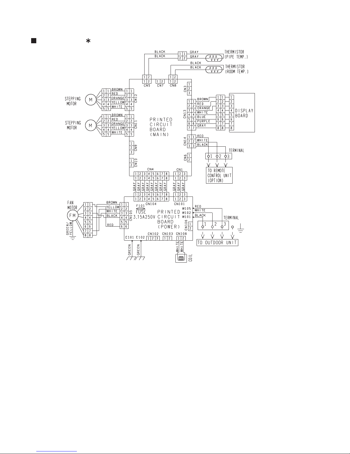
4. CIRCUIT DIAGRAMS
MODEL : AB A30 / 36 LBT
INDOOR UNIT
Page 14

04 - 02
MODEL : AO A30 /36 LBTL
OUTDOOR UNIT
Page 15

5 . DESCRIPTION OF EACH
CONTROL OPERATION
R410A
Large Ceiling type
INVERTER
Page 16

5-1. COOLING OPERATION
5-1-1 COOLING CAPACITY CONTROL
A sensor (room temperature thermistor) built in the indoor unit will usually perceive
difference or variation between a set temperature and present room temperature, and
controls the operation frequency of the compressor.
The maximum frequency is limited in the range shown in Figure 1 based on the fan speed mode
and the outdoor temperature.
* If the room temperature is 2 °C higher than a set temperature,
the compressor operation frequency will attain to maximum frequency.
* If the room temperature is 2.5 °C lower than a set temperature, the compressor
will be stopped.
* When the room temperature is between +2 °C to -2.5 °C of the setting temperature,
the compressor frequency is controlled within the range shown in Table1.
minimum
frequency
maximum
frequency
AO*A30LBTL
23Hz 94Hz
AO*A36LBTL
Outdoor air
temperature
( Table 1 : Compressor Frequency Range )
( Fig. 1 : Limit of Maximum Frequency based on Outdoor Temperature )
05-01
5. DESCRIPTION OF EACH CONTROL OPERATION
AO*A30LBTL
A zone
B zone
C zone
D zone
E zone
F zone
Me Lo Qu
Fan speed mode
Hi
A zone
36°C
34°C
B zone
32°C
30°C
C zone
21°C
19°C
D zone
12°C
10°C
E zone
2°C
0°C
F zone
When the room
temperature drops
When the room
temperature rises
94Hz 76Hz 64Hz 51Hz
94Hz 76Hz 64Hz 51Hz
85Hz 64Hz 57Hz 51Hz
64Hz 57Hz 51Hz 45Hz
AO*A36LBTL
Page 17

5-2. HEATING OPERATION
5-2-1 HEATING CAPACITY CONTROL
A sensor (room temperature thermistor) built in the indoor unit will usually perceive
difference or variation between a set temperature and present room temperature, and
controls the operation frequency of the compressor.
The maximum frequency is limited in the range shown in Figure 2 based on the outdoor temperature.
* If the room temperature is lower 3 °C than a set temperature,
the compressor operation frequency will attain to maximum frequency.
* If the room temperature is higher 2.5 °C than a set temperature, the compressor
will be stopped.
* When the room temperature is between +2.5 °C to -3 °C of the setting temperature,
the compressor frequency is controlled within the range shown in Table2.
( Table 2 : Compressor Frequency Range )
( Fig.2 : Limit of Maximum Frequency based on Outdoor Temperature )
05-02
minimum
frequency
maximum
frequency
AO*A30LBTL
23Hz
120Hz
AO*A36LBTL
AO*A30LBTL
C zone
19°C
C zone
B zone 120Hz 88Hz 76Hz 67Hz
17°C
A zone
14°C
B zone
12°C
A zone
Lo Qu
Fan speed mode
Hi Me
Outdoor air
temperature
When the room
temperature drops
When the room
temperature rises
AO*A36LBTL
Page 18

5-3. DRY OPERATION
5-3-1 INDOOR UNIT CONTROL
The compressor rotation frequency shall change according to set temperature and room
temperature variation which the room temperature sensor of the indoor unit has detected
as shown in the Fig 3.
( Table 3 : Compressor frequency )
05-03
Operating frequency
[ AB*A30LBTL ]
51Hz
Room
temperature
Room
temperature
Compressor ON
Ts+1.5 °C
Ts+0.5 °C
Compressor OFF
( Fig.3 : Compressor Control based on Room Temperature )
Ts : Setting temperature
Compressor
ON
OFF
Indoor fan
Dry air flow
S-Lo
OFF
( Fig.4 : Indoor Fan Control )
10 30 60 180 60 180 60 10 30
(sec)
[ AB*A36LBTL ]
X zone
Y zone
Temperature zone
0Hz
X zone
Y zone
[ AB*A30/36LBT : Dry air flow 650rpm, S-Lo 250rpm ]
Page 19

5-4. AUTO CHANGEOVER OPERATION
When the air conditioner is set to the AUTO mode by remote control, operation starts in the optimum
mode from among the HEATING, COOLING and MONITORING modes. During operation, the
optimum mode is automatically swiched in accordance with temperature changes. The temperature
can be set between 18°C and 30°C in 1 °C steps.
When operation starts, only the indoor fan is operated for 1 minute. (Air flow mode: S- Lo)
After 1 minute, depends on the room temperature and outdoor unit's operarion mode,
the operation mode is selected in accordance with the below.
( Table 4 : Operation mode selection table )
1
05-04
Room temperature :Tb
A zone
Tb > Ts +2 °C
Ts -2 °C > Tb
Ts +2 °C > Tb > Ts -2 °C
Monitoring
Monitoring
Heating
Ts : Setting temperature
B zone
Cooling
(Automatic Dry)
Monitoring
Heating
C zone
Monitoring
Monitoring
=
=
( Fig.5 : Operation mode selection based on Outdoor Temperature )
Cooling
(Automatic Dry)
[ For AB*A30/ 36LBT ]
A zone
B zone
C zone
32°C
-15°C
Outdoor temperature zone
When COOLING was selected at , the air conditioner operates as follow:
The same operation as COOLING OPERATION of item 5-1 above is performed.
However, the setting temperature is raised 1°C and the room temperature correct coefficient value is 0°C
When the compressor frequency have been below 23Hz for 8 minutes or the room temperature reaches
"setting temperature -1.5°C" , operation is automatically switched to DRY OPERATION of item 5-3 above
is performed.
However, compressor control based on room temperature is as follows.
If the room temperature reaches "setting temperature +2°C" during DRY operation,
operation returns to COOLING operation.
When HEATING was selected at , the same operation as HEATING OPERATION of item 5-2
above is performed. However, the room temperature correct coefficient value is 0°C.
When the compressor was stopped for 6 consecutive minutes by the temperature control function
after the COOLING or HEATING operation mode was selected at above, operation is switched
to MONITORING and the operation mode is selected again.
1
2
3
1
4
1
Room
temperature
Compressor :ON
Compressor :OFF
Ts - 0.5°C
Ts - 1.5°C
Outdoor
temperature
Page 20

5-5. INDOOR FAN CONTROL
1. Fan speed
( Table 5 : Indoor Fan Speed )
2. FAN OPERATION
The airflow can be switched in 5 steps such as AUTO, QU, LOW, MED, HIGH, while the indoor
fan only runs.
When [AUTO] is selected, the indoor fan motor runs continuously [MED] mode.
AB*A30LBT
Operation mode Air flow mode Speed (rpm)
Hi 1000
910
750
650
Me
Lo
Cooling
Qu
Hi 1000
1000
910
750
Me+
Me
Heating
Lo
AB*A36LBT
Operation mode Air flow mode Speed (rpm)
Hi 1100
910
750
650
Me
Lo
Cooling
Qu
Hi 1100
1100
910
750
Me+
Me
Heating
Lo
650
Qu
650
Qu
Auto
500
Dry
S-Lo 250
Monitoring
Auto
500
Dry
S-Lo 250
Monitoring
3. COOLING OPERATION
Switch the airflow [AUTO], and the indoor fan motor will run according to a room temperature,
as shown in Figure 5.
On the other hand, if switched in [HIGH] [QU], the indoor motor will run at a constant airflow of [COOL]
operation modes QU, LOW, MED, HIGH,as shown in Table 6.
( Fig.6 : Airflow change - over ( Cooling : AUTO ) )
When the room
temperature rises
When the room
temperature drops
TR : Room temperature
Ts : Setting temperature
TR-Ts > 2 °C
=
1 °C > TR-Ts
2 °C > TR-Ts > 1 °C
=
TR-Ts > 2.5 °C
=
1.5 °C > TR-Ts
2.5 °C > TR-Ts > 1.5 °C
=
HIGH mode
MED mode
LOW mode
650
Cool Air Prevention Cool Air Prevention
650
05-05
Page 21

4. HEATING OPERATION
Switch the airflow [AUTO], and the indoor fan motor will run according to a room temperature,
as shown in Figure 7.
On the other hand, if switched in [HIGH] [QU], the indoor motor will run at a constant airflow
of [HEAT] operation modes QU, LOW, MED, HIGH, as shown in Table 5.
5. COOL AIR PREVENTION CONTROL (Heating mode)
6. DRY OPERATION
Refer to the Figure 4.
During the dry mode operation, the fan speed setting can not be changed.
05-06
42°C
30°C
34°C
Indoor heat exchanger
temperature
Indoor heat exchanger
temperature
When the compressor operates, the maximum value of the indoor fan speed is set as shown in Figure 8,
based on the detected temperature by the indoor heat exchanger sensor on heating mode.
When the compressor does not operate, the indoor fan motor operates [S-Lo] mode.
( Fig.7 : Airflow change - over ( Heating : AUTO ) )
( Fig.8 : Cool Air Prevention Control )
< [Hi] setting >
Hi
Me+
Lo
Cool air
prevention
39°C
37°C
37°C
32°C
24°C
39°C
32°C
Indoor heat exchanger
temperature
Indoor heat exchanger
temperature
< The other of [Hi] setting >
S-Lo
Lo (Qu)
Cool air
prevention
37°C
30°C
34°C
24°C
Setting
FAN mode
S-Lo
TR-Ts > - 1.5 °C
=
- 2.5 °C> TR-Ts
- 1.5 °C> TR-Ts > - 2.5 °C
=
TR-Ts > - 1 °C
=
- 2 °C> TR-Ts
- 1 °C> TR-Ts > - 2 °C
=
When the room
temperature rises
When the room
temperature drops
TR : Room temperature
Ts : Setting temperature
LOW mode
MED mode
HIGH mode
[ AB*A30/36LBT : Cool air prevention 500rpm, S-Lo 250rpm ]
Page 22

5-6. OUTDOOR FAN CONTROL
1. Outdoor Fan Motor
1-1. For AO*A30/ 36LBTL ( AB*A30 / 36LBT , AR*A30 / 36LBTU )
Following table shows the fan speed of the outdoor unit.
Table 6 : Fan speed of the outdoor unit
Table 7 : Fan speed when starting up outdoor fan
Outdoor temperature [Ta]
The outdoor fan speed is changed in the range of the speed shown in the above table,
based on the frequency of the compressor.
(When the compressor frequency increases, the outdoor fan speed is also changed to
higher speed. If the compressor frequency decreases, the outdoor fan speed is changed
to the lower speed as well.)
After starting up the outdoor fan, it operates with the following speed for initial 20 seconds.
After operating the defrost control function on heating mode except economy operation,
its speed becomes 900rpm
regardless of the compressor frequency.
However, it returns to the normal speed control when the defrosting operation does not function
for 240 minutes after releasing the defrost operation or when the outdoor temperature sensor
detection value becomes higher than 5°C.
Cooling
Dry
900/ 850/ 780/ 700/ 500 rpm
500 rpm
AO*A30LBTL
Outdoor temperature zone
Fan speed
500 rpm
200 rpm
AO*A30LBTL
AO*A36LBTL
Heating
900/ 780/ 700/ 550/ 450 rpm
340/ 320/ 250/ rpm
2°C > Ta
260/ 250/ rpm
260/ 250/ rpm
12°C > Ta > 2°C
Ta > 12°C
12°C
2°C
10°C
0°C
D zone ( Normal )
F zone
G zone
Outdoor temperature zone
COOL D zone (Normal) / HEATING
COOL F,G zone
05-07
340/ 320/ 250/ rpm
AO*A36LBTL
AO*A30LBTL
850/ 780/ 700/ 500 rpm
500 rpm
340/ 320/ 250/ rpm
2°C > Ta
260/ 250/ rpm
260/ 250/ rpm
12°C > Ta > 2°C
Ta > 12°C
AO*A36LBTL
340/ 320/ 250/ rpm
Page 23

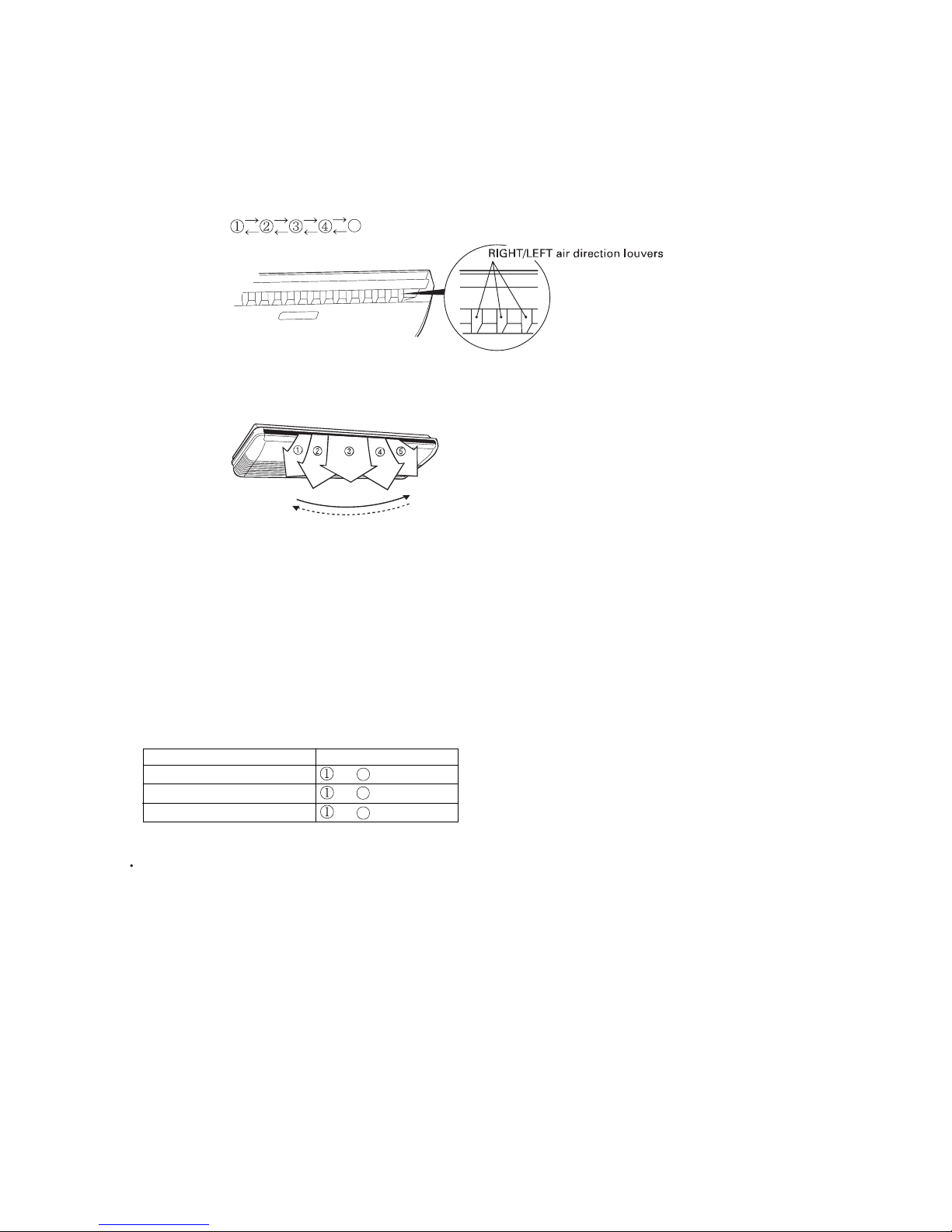
5-7. LOUVER CONTROL
05-08
1. VERTICAL LOUVER CONTROL (AB*A30 / 36LBT)
Each time the button is pressed, the air direction range will change as follows:
Use the air direction adjustments within the ranges shown above.
The vertical airflow direction is set automatically as shown, in accordance with the type of operation
selected.
Cooling / Dry / Fan mode Horizontal flow
Heating mode Downward flow
(Function Range)
(Fig.9 : Air Direction Range)
(Operation Range)
2. SWING OPERATION (AB*A30 / 36LBT)
When the swing signal is received from the remote controller, the vertical louver starts to swing.
The range of swing depends on the set airflow direction.
When the indoor fan is either at S-Lo or Stop mode, the swinging operation is interrupted
and the louver stops at the memorized position.
( Stop mode means Operation stop.)
During Cooling/Dry mode/Fan mode :
During Heating mode :
During AUTO mode operation, for the first minute after beginning operation, air -flow will be horizontal
; the air direction cannot be adjusted during this period.
The type of operation
Cooling/Dry/Fan
Range of swing
to
Heating
to
5
5
5
3
5
5
Page 24
05-09
3. HORIZONTAL LOUVER CONTROL (AB*A30 / 36LBT)
Each time the button is pressed, the air direction range will change as follows:
(Function Range)
(Fig.10 : Air Direction Range)
4. SWING OPERATION (AB*A30 / 36LBT)
When the swing signal is received from the remote controller, the horizontal louver starts to swing.
The range of swing depends on the set airflow direction.
When the indoor fan is either at S-Lo or Stop mode, the swinging operation is interrupted
and the louver stops at the memorized position.
( Stop mode means Operation stop.)
The type of operation
Cooling/Dry
Range of swing
to
Heating
to
5
FAN
to
5
Use the air direction adjustments within the ranges shown above.
The remote control unit's display does not change.
5
5
(All range)
(All range)
(All range)
Page 25

5-8. COMPRESSOR CONTROL
1. OPERATION FREQUENCY RANGE
The operation frequency of the compressor is different based on the operation mode as
shown in Table 9.
Cooling Heating
Min Max Min Max
Dry
(Table 9 : Compressor Operation Frequency Range)
2. OPERATION FREQUENCY CONTROL AT START UP
2-1. For AB*A30/ 36LBT
The compressor frequency soon after the start-up is controlled as shown in Figure 13.
(Fig.13 : Compressor Control at Start-up)
40Hz
60sec 100sec
59Hz
05-10
AB*A30LBT
23Hz
94Hz
23Hz
120Hz
51Hz
AB*A36LBT
46sec
Page 26

05-11
5-9. TIMER OPERATION CONTROL
AR-SY1
1. ON / OFF TIMER
OFF timer : When the clock reaches the set time, the air conditioner will be turned off.
Operation mode
Stop mode
Set time of timer
ON timer : When the clock reaches the set time, the air conditioner will be turned on.
Operation mode
Stop mode
Set time of timer
2. PROGRAM TIMER
5-9-1 Wireless Remote Controller
ON / TIMER
OFF / TIMER
PROGRAM TIMER
SLEEP TIMER
The program timer allows the OFF timer and ON timer to be used in combination one time.
Operation mode
Operation will start from the timer setting (either OFF timer or ON timer)
whichever is closest to the clock's current timer setting.
The order of operations is indicated by the arrow in the remote control unit's display.
SLEEP timer operation cannot be combined with ON timer operation.
Stop mode
Stop mode
Stop mode
Operation mode
Operation mode
Set time
Set time Set time Set time
Page 27

05-12
3. SLEEP TIMER
If the sleep timer is set, the room temperature is monitored and the operation is stopped automatically.
If the operation mode or the set temperature is change after the sleep timer is set, the operation is
continued according to the changed setting of the sleep timer from that time ON.
Set temperature rises
( Ts : Set temperature )
Stop of operation
Set temperature lowers
( Ts : Set temperature )
Ts
Stop of operation
In the cooling operation mode
When the sleep timer is set, the setting temperature is increased 1 degC.
It increases the setting temperature another 1 degC after 1 hour.
After that, the setting temperature is not changed and the operation is stopped at the time
of timer setting.
Ts
+1degC
+2degC
-2degC
-1degC
-4degC
-3degC
Set
60min
In the heating operation mode
When the sleep timer is set, the setting temperature is decreased 1 degC.
It decreases the setting temperature another 1 degC every 30 minutes.
Upon lowering 4 degC, the setting temperature is not changed and the operation stops
at the time of timer setting.
Set
30min
60min
90min
Page 28

5-10. ELECTRONIC EXPANSION VALVE CONTROL
5-11. TEST OPERATION CONTROL
Under the condition where the air conditioner stops, press the MASTER CONTROL button and
the FAN CONTROL button simultaneously for 2 seconds or more, and the test operation control
mode will appear.
During test running, " " will display on the remote controller display.
Set the test operation mode, and the compressor will continue to run regardless of whatever
the room temperature sensor detects.
The test operation mode is released if 60 minutes have passed after setting up the test operation.
The compressor won't enter operation status for 3 minutes after the compressor is stopped,
even if any operation is given.
5-12. PREVENT TO RESTART FOR 3 MINUTES ( 3 MINUTES ST )
05-13
With Wired Remote Controller
The most proper opening of the electronic expansion valve is calculated and controlled under the
present operating condition based on the following values.
The compressor frequency, the temperatures detected by the discharge temperature sensor, the
indoor heat exchanger sensor, the outdoor heat exchanger sensor, and the outdoor temperature
sensor.
Pulse range
53 480 pulse
(1) Pulse range of EEV
(2) The EEV is set up at 480 pulses when the compressor is stopped.
(3) Intialization (Input of 528 pulses toward closing direction) is operated under
the following condition.
* When the power is turned on.
* 4 hours has passed since the last initialization, and 3 minutes has passed after
the compressor stop.
(If 12 hours has passed since the last initialization, the compressor is compulsorily stopped.)
AB*A30LBT
AB*A36LBT
Cooling/ Dry
Heating
Operation
Under the condition where the air conditioner runs, press the TEST RUN button, and
the test operation control mode will appear.
During test running, the operation lamp and timer lamp of the air conditioner body twinkle simultaneously.
Set the test operation mode, and the compressor will continue to run regardless of whether the room
temperature sensor detects.
The test operation mode is released if 60 minutes have passed after setting up the test operation.
With Wireless Remote Controller
40 480 pulse
Page 29

At the time when the air conditioner is switched from the cooling mode to heating mode,
the compressor is stopped, and the 4-way valve is switched in 3 minutes later
after the compressor stopped.
When the power was interrupted by a power failure, etc. during operation, the operation contents
at that time are memorized and when power is recovered, operation is automatically resumed with
the memorized operation contents.
When the power is interrupted and recovered during timer operation, timer operation is canceled,
but only setting time is memorized.
[Operation contents memorized when the power is interrupted]
Operation mode
Set temperature
Set air flow
Timer mode and timer time
Thermistor detected position (When using the Wired Remote Controller)
5-13. 4-WAY VALVE EXTENSION SELECT
5-14. AUTO RESTART
05-14
5-15. PUMP DOWN ( For AB*A30/ 36LBT )
When the product is stopped:
1. Press the PUMP DOWN switch (SW2) on the outdoor unit.
(The LED on the outdoor unit circuit board starts lighting.
2. The pump down operation (cooling operation) begins right away.
After operation starts, close the 3-way valve (liquid).
3. After 2-3minutes, operation stops. Close the 3-way valve (gas) within 1minute after operations stops.
4. The LED will go out 3minutes after it stops. Disconnect the power supply after confirming that
the LED has gone out.
When the product is operating:
1. Press the PUMP DOWN switch (SW2) on the outdoor unit. The LED on the outdoor unit circuit board starts
flashing, and operation stops.
At this point, recovery has not been completed, so do not close the 3-way valves (liquid and gas).
2. The pump down operation (cooling operation) begins after 3minutes.
Close the 3-way valve (liquid) after operation starts.
3. After 2-3minutes, operation stops. Close the 3-way valve (gas) within 1minute after operations stops.
4. The LED will go out 3minutes after it stops. Disconnect the power supply after confirming that
the LED has gone out.
Perform the following procedures to collect the refrigerant when moving the indoor unit or the outdoor unit.
5-16. MANUAL AUTO OPERATION (When using the Wireless RC)
If MANUAL AUTO Button is set, the operation is controlled as shown in Table 10.
If the remote control is lost or battery power dissipated, this function will work without the remote
control.
OPERATION MODE
Auto changeover
Auto
Continuous
(No timer setting available)
24°C
(Table 10)
SETTING TEMP.
FAN CONT. MODE
TIMER MODE
Page 30

05-15
2. CONDITION OF THE DEFROST OPERATION COMPLETION
Release Condition
Outdoor heat exchanger temperature sensor value is higher than +13°C or
Compressor operation time has passed 15 minutes.
5-18. DEFROST OPERATION CONTROL
1. CONDITION OF STARTING THE DEFROST OPERATION
The defrost operation starts when the outdoor heat exchanger temperature sensor detects
the temperature lower than the values shown in Table 12.
(Table 12 : Condition of starting Defrost Operation)
1st time defrosting after starting operation
Less than 17 min.
17 to 62 min.
62 min. to 4 hours
After 4 hours
Does not operate
- 9°C
- 5°C
- 3°C
Compressor integrating
operation time
Compressor contiguous
operation time
Defrost operation is released when the conditions become as shown in Table 13.
(Table 13 : Defrost Release Condition)
Operation
temperature
Below 10 min.
Above 10 min.
Less than 35 min.
35 min. to 4 hours
After 4 hours
Does not operate
- 6°C
- 3°C
Compressor integrating
operation time
Compressor contiguous
operation time
Operation
temperature
Below 10 min.
Above 10 min.
Defrosting after 2nd time upon starting operation
5-17. COMPRESSOR PREHEATING
When the outdoor heat exchanger temperature is lower than 5°C and the heating operation
has been stopped for 30 minutes, power is applied to the compressor and the compressor is heated.
(By heating the compressor, warm air is quickly discharged when operation is started.)
When operation was started, and when the outdoor temperature rises to 7°C or greater,
preheating is ended.
Page 31

(Not defrosted for 10 minutes)
Outdoor fan : OFF
Compressor frequency : 0 Hz
EEV : 480pulse
4-way valve : OFF
Outdoor fan : OFF
Compressor frequency : 70Hz
Heating operation start : Compressor ON
Defrost Indicator:
[Operation lamp]
7 sec ON / 2 sec OFF
Outdoor heat exchanger temperature: Over 13°C
or
Compressor ON time: Over 15 minutes
Defrost end
05-16
Defrost start
3. Defrost Flow Chart
The defrosting shall proceed by the integrating operation time
and outdoor heat exchanger emperature as follows.
Compressor integrating
operation:
Over 17 minutes to
below 62 minutes
Compressor integrating
operation:
Over 240 minutes
Compressor integrating
operation:
Over 62 minutes to
below 240 minutes
Outdoor
heat exchanger
temperature:
Below - 9°C
Outdoor
heat exchanger
temperature:
Below - 5°C
Compressor integrating
operation:
Over 35 minutes to
below 240 minutes
Outdoor
heat exchanger
temperature:
Below - 6°C
Compressor integrating
operation:
Over 240 minutes
Outdoor
heat exchanger
temperature:
Below - 3°C
Outdoor
heat exchanger
temperature:
Below - 3°C
(In case of 1st defrost)
(In case of 2nd and later defrost)
AB*A30/ 36LBTL
Outdoor temp Outdoor heat exchanger
temperature:
Above 5 degC
Page 32

05-17
Release Condition
Outdoor heat exchanger temperature sensor value is higher than +10°C or
Compressor operation time has passed 15 minutes.
5-19. OFF DEFROST OPERATION CONTROL
1. OFF DEFROST OPERATION CONDITION
When operation stops in the [Heating operation] mode, if frost is adhered to the outdoor unit
heat exchanger, the defrost operation will proceed automatically.
In this time, if indoor unit operation lamp flashes slowly (7 sec ON / 2 sec OFF),
the outdoor unit will allow the heat exchanger to defrost, and then stop.
In heating operation, the outdoor heat exchanger temperature is less than - 4 C,
and compressor operation integrating time lasts for more than 30 minutes.
and compressor operation contiguous time lasts for more than 10 minutes.
OFF Defrost Flow Chart
Heating operation stop
2. OFF DEFROST END CONDITION
Outdoor heat exchanger temperature: Over 10°C
or
Compressor ON time: Over 15 minutes
Outdoor heat exchanger temperature:
Below - 4°C
and
Compressor integrating operation:
Over 30 minutes
and
Compressor contiguous operation:
Over 10 minutes
Defrost start
Defrost Indicator:
[Operation lamp]
7 sec ON / 2 sec OFF
Defrost end
Page 33

05-18
5-20. ECONOMY OPERATION
At the maximum output, ECONOMY OPERATION is approximately 70% of normal air conditioner operation
for cooling and heating.
When ECONOMY OPERATION is performed during the cooling mode,dehumidification is improved.
This function is especially convenient when you want to remove the humidity in the room
without significantly lowering the room temperature.
During ECONOMY OPERATION, the thermostat setting automatically changes according to the temperature
to avoid Unnecessary cooling and heating for the most economical operation.
If the room is not cooled (or heated) well during economy operation, select normal operation.
During the monitor period in the AUTO mode, the air conditioner operation will not change
to ECONOMY OPERATION even if ECONOMY OPERATION is selected by pressing the ECONOMY button.
Page 34

5-21. VARIOUS PROTECTIONS
1. DISCHARGE GAS TEMPERATURE OVER RISE PREVENTION CONTROL
The discharge gas thermosensor (discharge thermistor : Outdoor side) will detect discharge gas
temperature.
When the discharge temperature becomes higher than 104°C, the compressor frequency
is decreased 20 Hz, and it continues to decrease the frequency for 20 Hz every 120 seconds until
the temperature becomes lower than 101°C.
When the discharge temperature becomes lower than 101°C, the control of the compressor
frequency is released.
When the discharge temperature becomes higher than 110°C, the compressor stops
2. CURRENT RELEASE CONTROL
2-1. For AO*A 30/ 36LBTL
1-1. For AO*A 30/ 36LBTL
The compressor frequency is controlled so that the outdoor unit input current does not exceeds
the current limit velue that was set up with the outdoor temperature.
The compressor frequency returns to the designated frequency of the indoor unit at the time
when the frequency becomes lower than the release value.
(Table 13 : Current Release Operation Value / Release Value)
[ Heating ]
OT (Control / Release)
10.0A/ 9.5A
11.5A/ 11.0A
15.0A/ 14.5A
15.0A/ 14.5A
17°C
12°C
OT : Outdoor Temperature
5°C
AO*A30LBTL
OT (Control / Release)
10.0A/ 9.5A
11.5A/ 11.0A
15.0A/ 14.5A
18.0A/ 17.5A
17°C
12°C
OT : Outdoor Temperature
5°C
AO*A36LBTL
[ Cooling ]
OT (Control / Release)
10.0A/ 9.5A
13.0A/12.5A
15.0A/ 14.5A
46°C
40°C
OT : Outdoor Temperature
AO*A30LBTL
OT (Control / Release)
10.0A/ 9.5A
13.0A/ 12.5A
18.0A/ 17.5A
46°C
40°C
OT : Outdoor Temperature
AO*A36LBTL
50°C
9.0A/8.5A
50°C
12°C
12°C
2°C
2°C
14.5A/14.0A
14.5A/14.0A
13.0A/12.5A 13.0A/12.5A
9.0A/8.5A
05-19
Page 35

05-20
- 20°C
Cooling
Heating
5-22. COMPRESSOR STOP CONTROL
When the detection value of outdoor temperature sensor is lower than temperature
in the table below, the compressor is stopped.
(Table 15 : Operation temperature of compressor stop control)
Operation
temperature
Temperature
4. COOLING PRESSURE OVERRISE PROTECTION
When the outdoor unit heat exchange sensor temperature rises to 67°C or greater,
the compressor is stopped and trouble display is performed.
After 3 minutes ST, release of protection.
3. ANTIFREEZING CONTROL (Cooling and Dry mode)
The compressor frequency is decrease on cooling & dry mode when the indoor heat exchanger
temperature sensor detects the temperature lower than Temperature .
Then, the anti-freezing control is released when it becomes higher than Temperature .
(Table 14 : Anti-freezing Protection Operation / Release Temperature)
Outdoor temperature
Over than 10°C *1
or 12°C *2
Less than 10°C *1
or 12°C *2
*1. When the temperature rises.
*2. When the temperature drops.
4°C
7°C
13°C
Temperature Temperature
5. HIGH TEMPERATURE RELEASE CONTROL ( HEATING MODE )
On heating mode, the compressor frequency is controlled as following based on the
detection value of the indoor heat exchanger temperature sensor.
73Hz or greater 70Hz
70 36Hz
33 27Hz 23Hz
23Hz OFF
Indoor heat exchange
temperature
[ Control System ]
Refer to below
It returns to the normal operation
Compressor Operation
Frequency down every 120 sec
55°C
53°C
52°C
50°C
The compressor frequency is
decreased 3Hz every 60seconds.
Page 36

6 . REFRIGERANT CAUTION -R410A-
R410A
Large Ceiling type
INVERTER
Page 37

6-1. R410A TOOLS
Gauge manifold . . . . . . . . . . . . . . . . . . . . . (Fig.4-1)
Since the normal pressure is high, the connection pipe size
is also different.
Charge hose . . . . . . . . . . . . . . . . . . . . . . . (Fig.4-2)
Refrigerant cylinder . . . . . . . . . . . . . . . . . (Fig.4-3)
Confirm the refrigerant type before charging. Always
charge liquid-phase refrigerant.
Electronic balance for refrigerant
charging . . . . . . . . . . . . . . . . . . . . . . . . . . . (Fig.4-4)
Electronic balance is recommended as in the case of
R410A.
Vacuum pump with adapter to prevent
reverse flow . . . . . . . . . . . . . . . . . . . . . . . .(Fig.4-5)
Conventional pump can be used.
Vacuum holder . . . . . . . . . . . . . . . . . . . . . (Fig.4-6)
Conventional pump can be used if adapter for preventing
vacuum pump oil from flowing back is used.
Gas leakage tester . . . . . . . . . . . . . . . . . . (Fig.4-7)
Exclusive for HFC
Refrigerant cleaner . . . . . . . . . . . . . . . . . . (Fig.4-8)
Brown paint as designated by the ARI, USA
Flare tool . . . . . . . . . . . . . . . . . . . . . . . . . . (Fig.4-9)
Torque wrench . . . . . . . . . . . . . . . . . . . . (Fig.4-10)
Refrigerant recovering
equipment (Collector) . . . . . . . . . . . . . . (Fig.4-11)
The type which can be used for any refrigerant is available
Nitrogen cylinder . . . . . . . . . . . . . . . . . . . (Fig.4-12)
This prevents an oxide film from forming in the pipe silveralloy brazing work by turning the air out of the pipe and
preventing the inside combustion.
Safety charger . . . . . . . . . . . . . . . . . . . . . (Fig.4-13)
It is always compulsory to change the liquid, because
R410A is a mixed refrigerant and there is some fear that a
mixing ratio changes. In order to avoid the refrigerant from
returning to the compressor in a liquid state, the refrigerant
can be charged instead of giving a load to the compressor
with a safety charger.
Control valve . . . . . . . . . . . . . . . . . . . . . . (Fig.4-14)
The control valve prevents the refrigerant from spouting
when it is removed, as the charging hose side and the service port side are possible to open and close at the same
time.
Thermistor vacuum gauge . . . . . . . . . . . (Fig.4-15)
To remove moisture from the refrigerating cycle completely, it is necessary to perform appropriate vacuum drying.
For that reason, vacuum conditions can be confirmed certainly.
Vacuum valve . . . . . . . . . . . . . . . . . . . . . (Fig.4-16)
This valve builts in a check valve, and it is easily possible
to vacuum a refrigerating cycle or check for degree of vacuum with it.
TOOLS AND EQUIPMENT (R410A)
Gauge Manifold
R410A
R22, R407C
High
pressure
gauge
Compond
gauge
Port size
-0.1 5.3
Mpa
-0.1 3.8
Mpa
1/2UNF
5/16"
-0.1 3.5
Mpa
-0.1 1.7
Mpa
7/16UNF
1/4"
*
1
Charge hose
R410A
R22, R407C
Normal
pressure
Port size
5.1 Mpa
27.4 Mpa
1/2UNF
3.4 Mpa
17.2 Mpa
7/16UNF
*
2
Breaking
pressure
This air conditioner used R410A.
For installation and servicing, it is necessary to prepare the
tools and machines that are different from the previous
refrigerant.
Mark shows the exclusive use for R410A.
The specification of the gauge is different due
to higher pressure.
The size of connection pipe is also different to
prevent mis-use.
The shape of flare is different for
high pressure condition.
06-01
Gas charging
Vacuuming
Piping work
Pressure control and
Circuit switching
Charge hose
Fig.4-2
Outdoor unit
Electronic charging
scale Fig.4-4
Vacuum pump Fig.4-5
Thermistor vacuum gauge Fig.4-15
Vacuum
Valve Fig.4-16
Safety charger Fig.4-13
Control Valve
Fig.4-14
Vacuum holder Fig.4-6
Leakage tester Fig.4-7
Cleaner Fig.4-8
Collector Fig.4-11
Nitrogen Cylinder
Fig.4-12
Torque wrench
Fig.4-10
Flare tool
Fig.4-9
Gauge manifold
Fig.4-1
Fig.4-3
Refrigerant cylinder
Vacuum control
Low pressure
High pressure
side
side
6. REFRIGERANT CAUTION -R410A-
Page 38

6-2. PRECAUTION FOR INSTALLATION
06-02
Precaution for installation
The pipe must be properly pressure rated for R410A
The pipe must be an air-conditioning refrigerant pipe.
Flare and flare nuts
Diameter 1/4 ” (6.35mm) 3/8 ” (9.52mm) 1/2” (12.7mm)
Refrigerant
R410A
R22
/R407C
R410A R410A
A 9.1 9.0 13.2 13.0 16.6
16.2
B 13 12 20 15 13 20
C 12 11 16 12.5 19 16
Nut width 17 22 26 24
Always use the flare nut that is packed
with the product.
Do not use existing (for R22) pipes
•
Be sure to use new pipes when replacing
conventional (R22) model with HFC
(R407C, R410A) model.
•
If you use existing pipes, it may cause
resolution of compressor oil by remaining
mineral oil.
3/8” (15.88mm)
R410A
22
29
19.7
25
R22
/R407C
R22
/R407C
R22
/R407C
19.4
23
20
27
3/4” (19.05mm)
R410A
24
36
24
29
R22
/R407C
23.7
29
24
Material
Nominal diameter
(in)
1/4" 3/8" 1/2" 5/8" 3/4" 7/8" 1 1/8" 1 1/4" 1 1/2"1 3/8"1"
6.35 9.52 12.70 15.88 19.05 22.22 28.58 31.75 38.1034.9225.40
Outside diameter
(mm)
Wall thickness
(mm)
0.8 0.8 0.8 1.0 1.2 1.0 1.0 1.1 1.31.21.0
1) Allowable tensile stress 33 (N/mm );
>
=
2
2) Allowable tensile stress 61 (N/mm ); 3) Design pressure 4.2MPa.
>
=
2
JIS H3300-C1220T-H or equivalent
2)
COPPER
JIS H3300-C1220T-O or equivalent
1)
COPPER
3)
Pipe diameter, recommended material and wall thickness
A
C
B
Page 39

Be careful not to mix moisture and
contamination into the pipe
Moisture and contamination
in the pipe is a cause of
trouble.
Air purge
Always use a
vacuum pump
to purge air.
Refrigerant charge
Do it always from the liquid phase
side.
Don't charge from the gas phase side.
Compressor oil is changed
Be careful to handle synthetic oil, since it
resolves easily by moisture and
contamination.
Don't mix new synthetic oil and mineral oil.
It may cause trouble.
We developed new synthetic oil, since HFC
refrigerant doesn't dissolve in mineral (for R22)oil.
06-03
Page 40

6-3. PRECAUTION FOR SERVICING
Feature 1 Refrigerant oil is different from before.
Refrigerant oil for
New Refrigerant
Synthetic oil
Ether
Esther
Different point from
previous one
Previously it was
mineral oil.
Absorbent character
is high.
Contamination occurs
when mixed withe other
kind of oil.
Use the gauge manifold and charge hose
for New Refrigerant(HFC), which shall
be segregated from those of R22.
Attach the stop valve on the vacuum pump
and avoid the oil from reverse frow.
It is necessary to use the vacuum pump
which can obtain the high vacuum condition.
Precaution on Tools
Feature 2 New Refrigerant has Approx 1.6 times higher pressure than previous refrigerant.
R410A
High Pressure
Different point from
previous one
Diameter of Service port
has been changed from
1/4 Flare to 5/16 Flare.
It requires the gauge manifold and charge
hose exclusively for R410A.
It requires the flare tool and torque wrench
that satisfies New JIS standard.
Precaution on Tools
R410A R22
1.6 times of R22.
JIS standard of flare
process It became lager
To keep thethickness of
copper tube.
(1/4,3/3=more than 0.8mm)
Previous flare tool + flare adapter can be used as well.
06-04
Page 41

6-4. NEW REFRIGERANT R410A
What is HFC ?
Phase-out schedule of HCFC
according to Montreal protocol
1996 20102000 2004 2015 2020 2030
60
40
20
100
(Year)
(%)
80
(HCFC consumption of 1989) +
(CFC consumption of 1989) x 2.8%
65%
35%
10%
0.5%
started control
only service use
total abolition
100% =
0
*
06-05
Page 42

Ozone Layer depleting mechanism
CFC
CFCl
2
Cl Ozone
(O3)
O
2
ClO
Cl
sunbeam
What is CFC and HCFC?
CFC : Chloro-Fluoro-Carbon
High ODP( ozone depletion potential ) chemical compound, including chlorine. (ODP:0.6-1.0)
For example : R12 (for refrigerator and car air-conditioner)
Low ODP chemical compound, including chlorine and hydrogen. (ODP:0.02-01)
HCFC : Hydro-Chloro-Fluoro-Carbon
For example : R22 (for air-conditioner)
R134a (for Car air conditioner)
HFC3 : Hydro-Fluoro-Carbon
R407C (for air conditioner)
Refrigerant characteristics
R22
Composition
(wt%)
R22
(100)
Boiling Point
- 40.8
Behavior ---
Pressure at 54.5
C
(kPa)
2,151
Temperature Glide
(deg)
0
ODP 0.055
R407C
R32/R125/R134a
(23/25/52)
- 43.6
zeotrope
2,262
5.4
0
R410A
R32/R125
(50/50)
- 51.4
near azeotrope
3,406
0.11
0
06-06
Page 43

Summary of R407C and R410A characteristics
Pressure (Mpa) Temp ( C)
2.20 37.9
2.25 38.7
2.30 39.6
2.35 40.5
2.40 41.3
2.45 42.1
2.55 43.8
2.60 44.6
2.65 45.3
2.70 46.1
2.75 46.8
2.80 47.6
2.85 48.3
2.90 49.0
2.95 49.8
3.00 50.5
3.05 51.2
3.10 51.9
3.15 52.6
3.20 53.2
3.25 53.9
3.30 54.6
3.35 55.3
3.40 55.9
3.45 56.5
3.50 57.1
2.55 57.8
3.60 58.4
3.65 59.0
3.70 59.6
3.75 60.2
3.80 60.8
3.85 61.4
3.90 52.0
3.95 62.5
4.00 63.1
4.05 63.6
4.10 64.2
4.15 64.8
Temp ( C) Pressure (Mpa)
39 2.27
40 2.32
41 2.38
42 2.44
44 2.57
45 2.63
46 2.69
47 2.76
48 2.83
49 2.90
51 3.04
52 3.11
53 3.18
54 3.26
56 3.41
57 3.49
58 3.57
59 3.65
61 3.82
62 3.90
63 3.99
64 4.08
Desighed pressure of R410A refrigerant
< Pressure Temp >
Relation between R410A condensing temperature and saturated pressure.
< Temp Pressure >
Advantage
Disadvantage
Suitable for
R410A
higher system
performance
Near-Azeotropic
refrigerant
1.6 times higher
(difficult to design against
pressure resistance)
Small Air-Conditioners
pressure than R22
R407C
similar pressure as R22
(possible to design
large equipment)
Zeotropic refrigerant
(handle with care)
Large Air-Conditioners
*
05-07
Page 44

OIL
• Use new synthetic oils such as ester because HFC series refrigerant has less solubility with mineral oils
conventionally used for R22.
• As these new synthetic oils are easily influenced by moisture and dusts, they must be treated more care-
fully than the conventional lubricating oils.
CAUTION
For installation/servicing, take more precautions than the case of conventional refrigerants to avoid moisture
and dusts entering the refrigerant circuit. Also, for storing parts, more precautions must be taken.
2, 3-WAY VALVE
• Review material O-ring, valve core seal for securing suitability with oil.
CAUTION
Check if the valve is suitable for the refrigerant (model) when replacing.
CAUTION
Check if the compressor is suitable for the refrigerant (model) when replacing. Complete welding within 15minutes
after opening the cap when replacing.
COMPRESSOR
• Use better grade of material for sliding parts for securing good lubrication of sliding part as HFC
refrigerant does not contain chloride.
• Review insulating materials
• Increase pressure resistance strength
CAUTION
During storage, due care must be taken so that foreign matters such as dust and water do not enter.
HEAT EXCHANGER
• Review the water,contaminants controlling level
• Use thinner tube to increase pressure Increase capacity for resistance strength (only outdoor unit)
improving performance
CAUTION
Check if the valve is suitable for the refrigerant (model) when replacing.
4-WAY VALVE
• Review materials
6-5. DEFFERENCE FROM CONVENTIONAL MODEL (R22) AND PRECAUTIONS
06-08
Check Valve
Other Piping
CAUTION
Check if the valve is suitable for the refrigerant (model) when replacing.
• Review materials
Change shape of pipe ends to increase pressure resistance strength.
•
•
Review the water, contaminants controlling level.
Review thickness of pipes.
•
CAUTION
During storage, due care must be taken so that foreign matters such as dust and water do not enter.
Page 45

7 . TROUBLE SHOOTING
R410A
Large Ceiling type
INVERTER
Page 46

07-01
The OPERATION, TIMER and FILTER lamps operate as follows according to the error contents.
Error display
OPERATION TIMER
FILTER
(GREEN) (ORANGE)
(RED)
Error contents
:
0.5s ON / 0.5s OFF (Flash)
:
OFF
Indoor heat exchanger temperature
sensor error
Outdoor heat exchanger temperature
sensor(outlet) error
Outdoor discharge pipe temperature
sensor error
Compressor temperature sensor error
Outdoor temperature sensor error
Communication error
(Serial reverse transfer error)
Outdoor communication signal error
(Forward transfer signal error)
Trouble
shooting
Room temperature thermistor error
2
3
1
12
24
25
4
13
14
21
15
18
19
11
9
22
27
5
7
8
Discharge temperature error
Indoor fan motor abnormal
Outdoor unit fan motor error
Pressure switch error
Communication error
(Main PCB Display PCB)
Communication error
(Main PCB Display PCB)
IPM error
Compressor rotor location cannot detect
(permanent stop)
Compressor temperature error
Indoor manual auto switch error
Exessive high pressure protection on cooling
8 times
Communication error
(indoor unit remote control)
6 times
2 times
2 times
Water drain abnormal
6
6 times
2 times
3 times
2 times
2 times
3 times
3 times3 times
4 times3 times
2 times
4 times
2 times5 times
5 times5 times
6 times5 times
2 times7 times
3 times7 times
5 times7 times
28
4-way valve error
4 times7 times
6 times7 times
10
Indoor EEPROM abnormal (Model No.)
Continuous
blink
Continuous
blink
Continuous
blink
6 times
8 times
3 times
7 times
2 times
3 times
2 times
3 times
17
Active filter module (AFM) error
8 times
2 times
3 times
4 times
5 times
7. TROUBLESHOOTING
7-1 ERROR DISPLAY
7-1-1 INDOOR UNIT DISPLAY
Page 47

07-02
When "EE" in Temperature Display is displayed, inspection of the air conditioning system is necessary.
Please consult authoilzed servise personnel.
Error code
Error contents
Trouble
shooting
Communication error (Serial reverse transfer error)
Room temperature sensor error
Indoor heat exchanger temperature sensor error
Outdoor heat exchanger temperature sensor(outlet) error
Water drain abnormal
Outdoor temperature sensor error
Outdoor discharge pipe temperature sensor error
Discharge temperature error
Indoor fan motor abnormal
Outdoor unit fan motor error
Outdoor communication signal error (Forward transfer signal error)
7-1-2 WIRED REMOTE CONTROLLER DISPLAY
Pressure switch error
Active filter module (AFM) error
Communication error (indoor unit remote control)
Communication error (Main PCB Display PCB)
Communication error (Main PCB Display PCB)
IPM error
Compressor rotor location cannot detect (permanent stop)
Compressor temperature sensor error
Compressor temperature error
1. SELF - DIAGNOSIS
1
2
5
6
7
8
10
11
12
13
14
15
17
18
19
21
22
23
24
25
27
Indoor manual auto switch error
Exessive high pressure protection on cooling
PFC circuit error
3
4
SU MOTUWETH FR SA
Unit number (usually 0)
Error code
ex. Self-diagnosis check
Indoor EEPROM abnormal (Model No.)
9
If “CO” appears in the unit number display, there is a remote controller error.
Refer to the installation instruction sheet included with the remote controller.
28
4-way valve error
Page 48

07-03
2. ERROR CODE HISTORY DISPLAY
Up to 16 memorized error codes may be displayed for the indoor unit connected to the remote controller.
1. Stop the air conditioner operation.
2. Press the SET TEMPERATURE buttons , simultaneously for 3 seconds
or more to start the self-diagnosis.
4. Press the SET TEMPERATURE buttons , simultaneously for 3 seconds or more
or there is no key input for 60 seconds to stop the display.
3. Press the SET TEMPERATURE button to select the error history number.
SU MOTU WETH FR SA
Error code
Error history number
0 1 2 3 4 5 6 7
F E d c b A 9 8
Lower
Raise
Page 49

07-04
Active filter module (AFM) error
Operation LED Blinking Pattern
Normal operation OFF
5sec ON / 1sec OFF
0.5sec ON / 0.5sec OFF
0.1sec ON / 2sec OFF
0.1sec ON / 0.1sec OFF
5sec ON / 5sec OFF
5sec ON / 0.1sec OFF
Continuously lighting
Protected operation
1sec ON / 1sec OFF
Pump down operation
1. ERROR DISPLAY
7-1-3 OUTDOOR UNIT DISPLAY
Discharge temperature error
Outdoor unit fan motor error
19
Error contents
LED Flashing Pattern
Trouble
shooting
Outdoor unit sensor error
IPM error
Compressor rotor location cannot detect
15
9
5,7,8
17
18,30
2. NORMAL OPERATION DISPLAY
Page 50

Trouble shooting 1
INDOOR UNIT Error Method:
Detective Actuators:
Detective details:
Forecast of Cause:
Check Point 2 : Check Remote Control and Controller PCB
Check Point 1 : Check the connection of terminal
OKOK
Indicate or Display:
ERROR CODE : E : 00
Outdoor Unit : No indication
Communication Error
(Indoor unit Remote control)
Indoor unit controller PCB circuit
Wired Remote Control
1. Terminal connection abnormal 2. Wired Remote Control failure 3. Controller PCB failure
After turning off the power, check & correct the followings.
Check the connection of terminal between remote control and Indoor unit,
and check if there is a disconnection of the cable.
Upon correcting the removed connector or mis-wiring, reset the power.
Check Voltage at CN14 (terminal 1-3) of Controller PCB.
(Power supply to Remote Control)
>> If it is DC12V, Remote Control is failure. (Controller PCB is normal) >> Replace Remote Control
>> If it is DC 0V, Controller PCB is failure. (Check Remote Control once again) >> Replace Controller PCB
When the indoor unit cannot receive the signal from Wired Remote
more than 10seconds after power ON, or the indoor unit cannot receive
the signal more than 1minute during normal operation.
07-05
7-2 TROUBLE SHOOTING WITH ERROR CODE
Indoor Unit : Operation LED: OFF, Timer LED: 8 times blink,
Filter LED : OFF
Page 51

Trouble shooting 2
OUTDOOR UNIT Error Method:
Detective Actuators:
Detective details:
Forecast of Cause:
OK
Indicate or Display:
Outdoor Unit : No indication
ERROR CODE : E : 01
YESYES
NO
N
L
3
2
1
WHITE
BLACK
RED
WHITE
BLACK
+
-
OK
Communication Error
(Serial Reverse Transfer Error)
Outdoor Unit Main PCB Circuit
Active Filter Module
1. Connection failure 2. External cause 3. Main PCB failure 4. Active Filter Module failure
Check Point 1-1 : Reset the power and operate
Does Error indication show again?
Check Point 1-2:
Check external cause such as noise
Check the complete insulation of the grounding.
Check if there is any equipment that causes harmonic wave
near the power cable (Neon light bulb or any electronic
equipment which causes harmonic wave).
Check Point 2 : Check Connection
Check any loose or removed connection line of
Indoor unit and Outdoor unit.
>> If there is an abnormal condition, correct it by
referring to Installation Manual or Data &
Technical Manual.
Check connection between Outdoor Unit Main PCB
and Filter PCB.
(If there is loose connector or open cable)
Check Point 3 : Check the voltage of power supply
Check the voltage of power supply
>> Check if AC198 - 264V appears at Outdoor Unit Terminal L - N.
Check Point 4 : Check Serial Signal (Reverse Transfer Signal)
Check Serial Signal (Reverse Transfer Signal)
>> Check if Indicated value swings between AC70V and AC130V at Outdoor Unit Terminal 1 - 3.
>> If it is abnormal, Check Active Filter Module. (PARTS INFORMATION 3)
When the indoor unit cannot receive the serial signal from Outdoor unit
more than 10seconds,
then permanent stop after 20seconds.
>>If Active Filter Module is abnormal, replace it.
>>If Active Filter Module is normal, replace Main PCB.
07-06
Indoor Unit : Operation LED: OFF, Timer LED: 2 or 3 times blink,
Filter LED : OFF
Page 52

Trouble shooting 3
INDOOR UNIT Error Method:
Indicate or Display:
Outdoor Unit : No indication
ERROR CODE : E : 02
Detective Actuators:
Detective details:
Forecast of Cause :
Check Point 2 : Check Point 2 : Remove connector and check Thermistor resistance value
Check Point 1 : Check connection of Connector
Check Point 3 : Check Point 3 : Check voltage of Controller PCB (DC5.0V)
6.51
35°C
8.04
30°C
10.012.515.820.225.933.6Resistance Value (k )
25°C20°C15°C10°C5°C0°C
Temperature
OK
OK
3.594.355.30Resistance Value (k )
50°C45°C40°C
Temperature
THERMISTOR
(PIPE TEMP.)
THERMISTOR
(ROOM TEMP.)
BLACK
BLACK
BLACK
BLACK
CN5 CN7 CN8
1 2 1 2
1 2
1 1
2 2
1 2
Room Temperature Sensor Error
Indoor Unit Controller PCB Circuit
Room Temperature Thermistor
When Room Temperature Thermistor open or short-circuit is
detected at power ON.
1. Connector connection failure 2.Thermistor failure 3. Controller PCB failure
Check if connector is removed.
Check erroneous connection.
Check if thermistor cable is open.
>>Upon correcting the removed connector or mis-wiring, reset the power.
Thermistor Characteristics (Approx. value)
If Thermistor is either open or shorted, replace it and reset the power.
Make sure circuit diagram of indoor unit and check terminal voltage at Thermistor (DC5.0V)
If the voltage does not appear, replace Controller PCB.
07-07
1 2
Indoor Unit : Operation LED: 2 times blink, Timer LED: 2 times blink,
Filter LED : OFF
GRAY
GRAY
Page 53

Trouble shooting 4
INDOOR UNIT
INDOOR UNIT Error Method:
Indicate or Display:
Outdoor Unit : No indication
ERROR CODE : E : 04
Detective Actuators:
Detective details:
Forecast of Cause :
Check Point 2 :
31.7
35°C
39.6
30°C
49.762.980.3103134176Resistance Value (k )
25°C20°C15°C10°C5°C0°C
Temperature
OKOK
OK
17.120.825.6Resistance Value (k )
50°C45°C40°C
Temperature
Indoor Heat Exchanger Temperature
Sensor Error
Indoor Unit Controller PCB Circuit
Heat Exchanger Temperature Thermistor
When Heat Exchanger Temperature Thermistor open or short-circuit is
detected at power ON.
1. Connector connection failure 2.Thermistor failure 3. Controller PCB failure
Check Point 1 : Check connection of Connector
Check if connector is removed.
Check erroneous connection.
Check if thermistor cable is open.
>>Upon correcting the removed connector or mis-wiring, reset the power.
Check Point 2 : Remove connector and check Thermistor resistance value
Thermistor Characteristics (Approx. value)
If Thermistor is either open or shorted, replace it and reset the power.
Check Point 3 : Check voltage of Controller PCB (DC5.0V)
Make sure circuit diagram of indoor unit and check terminal voltage at Thermistor (DC5.0V)
If the voltage does not appear, replace Controller PCB.
07-08
THERMISTOR
(PIPE TEMP.)
THERMISTOR
(ROOM TEMP.)
BLACK
BLACK
BLACK
BLACK
CN5 CN7 CN8
1 2 1 2
1 2 1 21 2
Indoor Unit : Operation LED: 2 times blink, Timer LED: 3 times blink,
Filter LED : OFF
1 1
2 2
GRAY
GRAY
Page 54

Trouble shooting 5
OUTDOOR UNIT Error Method:
Indicate or Display:
Outdoor Unit : LED 0.1sec ON/ 0.1sec OFF
ERROR CODE : E : 06
Detective Actuators:
Detective details:
Forecast of Cause :
Check Point 2 :
Check Point 3 :
4.77
25°C
5.98
20°C
7.569.6312.416.121.027.8Resistance Value (k )
15°C10°C5°C0°C-5°C-10°C
Temperature
OKOK
OKOK
DC
3.84
30°C
0.446
90°C
0.606
80°C
0.8401.191.712.082.533.11Resistance Value (k )
70°C60°C50°C45°C40°C35°C
Temperature
0.333
100°C
THERMISTOR
(DISCHARGE)
THERMISTOR
(COMPRESSOR)
THERMISTOR
(PIPE)
THERMISTOR
(OUTDOOR)
BLACK
BLUE
CN64 CN62 CN65 CN63
3 2 1
BROWN
BROWN
Outdoor Heat Exchanger Temperature
Sensor (Outlet) Error
Outdoor Unit Main PCB Circuit
Heat Exchanger Temperature
Thermistor (Outlet)
When Heat Exchanger Temperature Thermistor (Outlet) open or
short-circuit is detected at power ON or while running the compressor.
1. Connector connection failure 2.Thermistor failure 3. Main PCB failure
Check Point 1 : Check connection of Connector
Check if connector is removed.
Check erroneous connection.
Check if thermistor cable is open.
>>Upon correcting the removed connector or mis-wiring, reset the power.
Check Point 2 : Remove connector and check Thermistor resistance value
Thermistor Characteristics (Approx. value)
If Thermistor is either open or shorted, replace it and reset the power.
Check Point 3 : Check voltage of Main PCB (DC5.0V)
Make sure circuit diagram of outdoor unit and check terminal voltage at Thermistor (DC5.0V)
If the voltage does not appear, replace Main PCB.
07-09
3 2 1
3 2 1
3 2 1
3 2 1
3 2 1
3 2 1
3 2 1
Indoor Unit : Operation LED: 3 times blink, Timer LED: 3 times blink,
Filter LED : OFF
Page 55

Check Point 2 : Check Point 2 : Check Connector (CN15) / Wire
Check Point 1 : Check Float Switch
Check Point 3 : Replace Controller PCB
ONON OFFOFF
OKOK
OKOK
Trouble shooting 6
INDOOR UNIT Error Method:
Indicate or Display:
Outdoor Unit : No indication
ERROR CODE : E : 09
Detective Actuators:
Detective details:
Forecast of Cause :
Water Drain Abnormal
Indoor Unit Controller PCB Circuit
Float Switch
When Float Switch is ON for more than 3 minutes.
1. Float Switch failure 2. Shorted connector/ wire 3. Controller PCB failure
Check operation of float switch. (any blocking by dust, etc.)
Remove Float switch and check ON/OFF switching operation
by using a meter.
>>If Float switch is detective, replace it.
Check loose contact of CN15 /shorted wire (pinched wire).
>>Replace Float switch if the wire is abnormal
If Check Point 1 & 2 do not improve the symptom, change Controller PCB.
07-10
Indoor Unit : Operation LED: 2 times blink, Timer LED: 6 times blink,
Filter LED : OFF
Page 56

Trouble shooting 7
OUTDOOR UNIT Error Method:
Indicate or Display:
ERROR CODE : E : 0A
Detective Actuators:
Detective details:
Forecast of Cause :
Check Point 2 :
Check Point 3 :
OKOK
OKOK
30°C
12.620.726.935.246.662.3115Resistance Value (k )
20°C
16.1
15°C10°C5°C0°C-20°C -10°C -5°C
Temperature
3.45 2.36 1.65Resistance Value (k )
50°C 60°C 70°C
5.187.97
40°C
Temperature
Outdoor Temperature Sensor Error
Outdoor Unit Main PCB Circuit
Outdoor Temperature Thermistor
When Outdoor Temperature Thermistor open or short-circuit is
detected at power ON or while running the compressor.
1. Connector connection failure 2.Thermistor failure 3. Main PCB failure
Check Point 1 : Check connection of Connector
Check if connector is removed.
Check erroneous connection.
Check if thermistor cable is open.
>>Upon correcting the removed connector or mis-wiring, reset the power.
Check Point 2 : Remove connector and check Thermistor resistance value
Thermistor Characteristics (Approx. value)
If Thermistor is either open or shorted, replace it and reset the power.
Check Point 3 : Check voltage of Main PCB (DC5.0V)
Make sure circuit diagram of outdoor unit and check terminal voltage at Thermistor (DC5.0V)
If the voltage does not appear, replace Main PCB.
07-11
Outdoor Unit : LED 0.1sec ON/ 0.1sec OFF
Indoor Unit : Operation LED: 3 times blink, Timer LED: 4 times blink,
Filter LED : OFF
THERMISTOR
(DISCHARGE)
THERMISTOR
(COMPRESSOR)
THERMISTOR
(PIPE)
THERMISTOR
(OUTDOOR)
BLACK
BLUE
CN64 CN62 CN65 CN63
3 2 1
BROWN
BROWN
3 2 1
3 2 1
3 2 1
3 2 1
3 2 1
3 2 1
3 2 1
Page 57

Trouble shooting 8
OUTDOOR UNIT Error Method:
Indicate or Display:
ERROR CODE : E : 0C
Detective Actuators:
Detective details:
Forecast of Cause :
Check Point 2 :
Check Point 3 :
17.826.3
20°C
40.062.679.1101130169Resistance Value (k )
15°C10°C5°C0°C
Temperature
OKOK
OKOK
12.3
30°C
50°C40°C
60°C
1.222.003.434.606.278.70Resistance Value (k )
140°C120°C100°C90°C80°C70°C
Temperature
Outdoor Discharge Pipe Temperature
Sensor Error
Outdoor Unit Main PCB Circuit
Discharge Pipe Temperature Thermistor
When Discharge Pipe Temperature Thermistor open or short-circuit
is detected at power ON or while running the compressor.
1. Connector connection failure 2.Thermistor failure 3. Main PCB failure
Check Point 1 : Check connection of Connector
Check if connector is removed.
Check erroneous connection.
Check if thermistor cable is open.
>>Upon correcting the removed connector or mis-wiring, reset the power.
Check Point 2 : Remove connector and check Thermistor resistance value
Thermistor Characteristics (Approx. value)
If Thermistor is either open or shorted, replace it and reset the power.
Check Point 3 : Check voltage of Main PCB (DC5.0V)
Make sure circuit diagram of outdoor unit and check terminal voltage at Thermistor (DC5.0V)
If the voltage does not appear, replace Main PCB.
07-12
Outdoor Unit : LED 0.1sec ON/ 0.1sec OFF
Indoor Unit : Operation LED: 3 times blink, Timer LED: 2 times blink,
Filter LED : OFF
THERMISTOR
(DISCHARGE)
THERMISTOR
(COMPRESSOR)
THERMISTOR
(PIPE)
THERMISTOR
(OUTDOOR)
BLACK
BLUE
CN64 CN62 CN65 CN63
3 2 1
BROWN
BROWN
3 2 1
3 2 1
3 2 1
3 2 1
3 2 1
3 2 1
3 2 1
Page 58

Trouble shooting 9
INDOOR UNIT
OUTDOOR UNIT Error Method:
Indicate or Display:
ERROR CODE : E : 0F
Detective Actuators:
Detective details:
Forecast of Cause :
Discharge temperature error
Outdoor Unit Main PCB Circuit
Discharge Pipe Temperature Thermistor
07-13
Outdoor Unit : LED continuously lighting
When the discharge temperature becomes higher than 110°C
( AB*A36L and 45L is 115°C ), the compressor stops.
After the compressor restarts, if the same operation is repeated,
the compressor stops permanently.
Check Point 1 : Check if Gas Valve is open
If it is not open, open it and check the operation.
Check Point 3 : Check if gas leak or less gas
Measure Gas pressure, if there is a leak, correct it.
>>If recharging refrigerant, make sure to perform
vacuuming and recharge the specified amount.
Check Point 5 : Check Outdoor FAN, Heat Exchanger
Is there anything obstructing the air distribution circuit?
Is there any clogging of Outdoor Heat Exchanger?
Is the Fan rotating? (Check by hand and if it is locked, replace the motor)
Check Outdoor Fan Motor.
>>If the Fan Motor is defective, replace it.
Check Point 4 : Check Discharge Thermistor
Isn’t it fallen off the holder?
Is there a cable pinched?
>> Check characteristics of thermistor (Refer to Trouble shooting 8),
If defective, replace the thermistor
Check Point 2 : Check EEV and Strainer
Are EEV and Strainer open?
(Refer to PARTS INFORMATION 4)
>>If EEV or Strainer is defective, replace it.
OK OK
OK
OK
OK
OK
MPa MPa
1. Valve is close 2. EEV failure 3. Gas Leak, less 4. Discharge Thermistor failure
5. Outdoor Fan Operation failure 6. Outdoor Heat Exchanger clogged
< Cooling mode >
< Heating mode >
Check Point 1 : Check if LIquid Valve is open
If it is not open, open it and check the operation.
Check Point 2 : Check EEV and Strainer
Are EEV and Strainer open?
(Refer to PARTS INFORMATION 4)
>>If EEV or Strainer is defective, replace it.
Indoor Unit : Operation LED: 7 times blink, Timer LED: 2 times blink,
Filter LED : OFF
Page 59

Detective Actuators:
Detective details:
Forecast of Cause:
Check Point 3 : Replace Controller PCB
Check Point 2 :
Check Indoor Unit electric components
YESYES
NO
Trouble shooting 10
INDOOR UNIT Error Method:
Indicate or Display:
Outdoor Unit : No indication
ERROR CODE : E : 11
Indoor EEPROM abnormal
(Model No.)
Indoor Unit Controller PCB circuit
1. External cause 2. Defective connection of electric components 3. Controller PCB failure
Check Point 1-1 : Reset Power Supply and operate
Does Error indication show again?
Check Point 1-2 :
Check external cause at Indoor and Outdoor
(Voltage drop or Noise)
Instant drop : Check if there is a large load electric apparatus
in the same circuit.
Momentary power failure : Check if there is a defective contact
or leak current in the power supply
circuit.
Noise : Check if there is any equipment causing harmonic
wave near electric line.(Neon bulb or electric
equipment that may cause harmonic wave)
Check the complete insulation of grounding.
Note : EEPROM
EEPROM(Electronically Erasable and
Programmable Read Only Memory) is a nonvolatile memory which keeps memorized
information even if power is turned off. It can
change the contents electronically.
To change the contents, it uses higher
voltage than normal, and it can not change a
partial contents. (Rewriting shall be done
upon erasing the all contents.)
There is a limit in a number of rewriting.
Change Controller PCB.
Check all connectors.
(loose connector or incorrect wiring)
Check any shortage or corrosion on PCB.
When the model information being read from EEPROM has
an apparent error.
07-14
Indoor Unit : Operation LED: Blink, Timer LED: Blink,
Filter LED : Blink
Page 60

Trouble shooting 11
INDOOR UNIT Error Method:
Detective Actuators:
Detective details:
Forecast of Cause:
Check Point 1 : Check rotation of Fan
Check Point 2 : Check ambient temp. around motor
OK
OK
Indicate or Display:
Outdoor Unit : No indication
ERROR CODE : E : 12
Indoor Fan Motor abnormal
Indoor Unit Controller PCB Circuit
Indoor Fan Motor
1. Fan rotation failure 2. Fan motor winding open 3. Motor protection by surrounding temperature rise
4. Control PCB failure
Rotate the fan by hand when operation is off.
(Check if fan is caught, dropped off or locked motor)
>>If Fan or Bearing is abnormal, replace it.
Check excessively high temperature around the motor.
(If there is any surrounding equipment that causes heat)
>>Upon the temperature coming down, restart operation.
When the condition that actual frequency of Indoor Fan is
below 1/3 of target frequency is continued more than 56 seconds.
07-15
Check Point 3 : Replace Controller PCB
If Check Point 1- 2 do not improve the symptom, replace Controller PCB.
Indoor Unit : Operation LED: 6 times blink, Timer LED: 2, 3 times blink,
Filter LED : OFF
Page 61

Trouble shooting 12
INDOOR UNIT Error Method:
Detective Actuators:
Detective details:
Forecast of Cause:
Check Point 2 : Check Connection
OK
Indicate or Display:
ERROR CODE : E : 13
Check Point 3 : Check the voltage of power supply
Check Point 1-1 : Reset the power
YESYES
NO
Check Point 1-2:
N
L
3
2
1
WHITE
BLACK
RED
WHITE
BLACK
+
-
OK
Check Point 4 : Check Serial Signal (Forward Transfer Signal)
Check Serial Signal (Forward Transfer Signal)
Outdoor Communication Signal Error
(Forward Transfer Signal Error)
Indoor Unit Controller PCB Circuit
1. Connection failure 2. External cause 3. Controller PCB failure
Does Error indication reappear?
Check external cause such as noise
Check the complete insulation of the grounding.
Check if there is any equipment that causes harmonic wave
near the power cable (Neon light bulb or any electronic
equipment which causes harmonic wave).
Check the voltage of power supply
>> Check if AC198 - 264V appears at Outdoor Unit Terminal L - N.
>> Check if Indicated value swings between AC70V and AC130V at Outdoor Unit Terminal 2 - 3.
Check any loose or removed connection line of
Indoor unit and Outdoor unit.
>> If there is an abnormal condition, correct it by
referring to Installation Manual or Data &
Technical Manual.
Check connection between Indoor Unit Controller PCB
and Filter PCB.
(If there is loose connector or open cable)
>> If it is abnormal, Controller PCB is failure. >> Replace Controller PCB
07-16
When the outdoor unit cannot receive the serial signal from Indoor unit
more than 10seconds.
Outdoor Unit : No indication
Indoor Unit : Operation LED: OFF, Timer LED: 4, 5 times blink,
Filter LED : OFF
Page 62

Trouble shooting 13
OUTDOOR UNIT Error Method:
Indicate or Display:
ERROR CODE : E : 15
Detective Actuators:
Detective details:
Forecast of Cause :
Check Point 2 :
Check Point 3 :
OKOK
OKOK
Compressor Temperature Sensor Error
Outdoor Unit Main PCB Circuit
Compressor Temperature Thermistor
When Compressor Temperature Thermistor open or short-circuit is
detected at power ON or while running the compressor.
1. Connector connection failure 2. Thermistor failure 3. Main PCB failure
Check Point 1 : Check connection of Connector
Check if connector is removed.
Check erroneous connection.
Check if thermistor cable is open.
>>Upon correcting the removed connector or mis-wiring, reset the power.
Check Point 2 : Remove connector and check Thermistor resistance value
Thermistor Characteristics (Rough value)
If Thermistor is either open or shorted, replace it and reset the power.
Check Point 3 : Check voltage of Main PCB (DC5.0V)
Make sure circuit diagram of outdoor unit and check terminal voltage at Thermistor (DC5.0V)
If the voltage does not appear, replace Main PCB.
07-17
Outdoor Unit : LED 0.1sec ON/ 0.1sec OFF
17.826.3
20°C
40.062.679.1101130169Resistance Value (k )
15°C10°C5°C0°C
Temperature
12.3
30°C
50°C40°C
60°C
1.222.003.434.606.278.70Resistance Value (k )
140°C120°C100°C
90°C80°C70°C
Temperature
Indoor Unit : Operation LED: 3 times blink, Timer LED: 8 times blink,
Filter LED : OFF
THERMISTOR
(DISCHARGE)
THERMISTOR
(COMPRESSOR)
THERMISTOR
(PIPE)
THERMISTOR
(OUTDOOR)
BLACK
BLUE
CN64 CN62 CN65 CN63
3 2 1
BROWN
BROWN
3 2 1
3 2 1
3 2 1
3 2 1
3 2 1
3 2 1
3 2 1
Page 63

Trouble shooting 14
OUTDOOR UNIT Error Method:
Indicate or Display:
ERROR CODE : E : 16
Detective Actuators:
Detective details:
Forecast of Cause :
Check Point 3 : Check Point 2 : Check voltage of Main PCB (DC5.0V)
HIGH PRESSURE SW
RED
RED
CN90
212
1
OK
Check Point 1 : Reset Power Supply and operate
Check Point 3 : Check Pressure Switch
YES
NONO
OK
Pressure Switch Error
Outdoor Unit Main PCB Circuit
Pressure Switch
1. Connector connection failure 2. Pressure Switch failure 3. Main PCB failure
When pressure switch open is detected in 10 seconds
after the power is turned on.
Does abnormal LED indication show again?
Make sure circuit diagram of outdoor unit and check terminal voltage
at Pressure Switch. (DC5.0V)
If the voltage does not appear, replace Main PCB.
Check if connector is loose or cable is open.
>> If no abnormal connection is found,
replace Pressure Switch.
After replacing Pressure Switch, check operating
condition and pressure in operation.
Check Point 4 : Check High Pressure Protection on cooling
Check Excessive high pressure protection on cooling.
(Refer to Trouble shooting 22)
07-18
Outdoor Unit : No indication
Indoor Unit : Operation LED: 7 times blink, Timer LED: 5 times blink,
Filter LED : OFF
Page 64

Trouble shooting 15
OUTDOOR UNIT Error Method:
Detective Actuators:
Detective details:
Forecast of Cause :
Check Point 3 : Check Outdoor Fan
OK
OK
Indicate or Display:
ERROR CODE : E : 17
Check Point 5 : Replace Main PCB
OKOK
OKOK
Check Point 1 : Check connections of Outdoor Unit Electrical Components
IPM error (Permanent Stop)
Outdoor Unit Main PCB Circuit
Compressor
1. Defective connection of electric components 2. Outdoor Fan Operation failure
3. Outdoor Heat Exchanger clogged 4. Compressor failure 5. Main PCB failure
Check if connector is removed.
Check if the terminal connection is loose.
Check erroneous connection.
Check if cable is open.
>>Upon correcting the removed connector or mis-wiring, reset the power.
Check Point 2 : Check Outdoor Fan, Heat Exchanger
Is there anything obstructing the air distribution circuit?
Is there any clogging of Outdoor Heat Exchanger?
Is the Fan rotating by hand when operation is off ?
>> If the Fan Motor is locked, replace it.
Check Outdoor Fan Motor. (Refer to Trouble shooting 19)
>> If the Fan Motor is failure, replace it.
Check Point 4 : Check Compressor
(PARTS INFORMATION 2)
Check Compressor.
If Check Point 1 4 do not improve the symptom, change Main PCB.
When more than normal operating current to IPM in Main PCB flows,
the compressor stops.
After the compressor restarts, if the same operation is repeated within 40sec,
the compressor stops again.
If and repeats 5 times, the compressor stops permanently.
07-19
Outdoor Unit : LED 0.5sec ON/ 0.5sec OFF
Indoor Unit : Operation LED: 5 times blink, Timer LED: 2 times blink,
Filter LED : OFF
Page 65

Trouble shooting 17
OUTDOOR UNIT Error Method:
Indicate or Display:
ERROR CODE : E : 19
Detective Actuators:
Detective details:
Forecast of Cause :
Check Point 3 : Check Active Filter Module
OKOK
OKOK
OKOK
Active Filter Module (AFM) error
Outdoor Unit Main PCB Circuit
Active Filter Module
1. External cause 2. Connector connection failure 3. Active Filter Module failure 4. Main PCB failure
Check Point 2 : Check connection of Connector
Check if connector is removed.
Check erroneous connection.
Check if cable is open.
>>Upon correcting the removed connector or mis-wiring, reset the power.
Check Active Filter Module. (PARTS INFORMATION 3)
>>If Active Filter Module is abnormal, replace it.
Check Point 4 : Replace Main PCB
If Check Point 1 3 do not improve the symptom, change Main PCB.
Check Point 1 : Check external cause at Indoor and Outdoor (Voltage drop or Noise)
Instant drop : Check if there is a large load electric apparatus in the same circuit.
Momentary power failure : Check if there is a defective contact or leak current
in the power supply circuit.
Noise : Check if there is any equipment causing harmonic wave near electric line.
(Neon bulb or electric equipment that may cause harmonic wave)
Check the complete insulation of grounding.
07-20
When inverter input DC voltage is higher than 425V or
lower than 80V.
When a momentary power cut off occurred on low voltage.
Indoor Unit : Operation LED: 8 times blink, Timer LED: 2, 3 times blink,
Filter LED : OFF
Outdoor Unit : LED 5sec ON/ 0.1sec OFF
Page 66

Trouble shooting 18
OUTDOOR UNIT Error Method:
Detective Actuators:
Detective details:
Forecast of Cause :
Check Point 2 : Check connection of around the Compressor components
OKOK
OKOK
Indicate or Display:
ERROR CODE : E : 1A
Check Point 3: Replace Main PCB
Outdoor Unit Main PCB Circuit
Compressor
Compressor rotor location cannot detect
(Permanent Stop)
1. Defective connection of electric components 2. Main PCB failure 3. Compressor failure
If Check Point 1,2 do not improve the symptom, change Main PCB.
Check if connector is removed.
Check erroneous connection.
Check if cable is open.
>>Upon correcting the removed connector or mis-wiring, reset the power.
(Refer to PARTS INFORMATION 2)
For Compressor Terminal, Main PCB
While running the compressor, if the detected rotor location is out of
phase with actual rotor location more than 90 degrees,
the compressor stops.
After the compressor restarts, if the same operation is repeated
within 40sec, the compressor stops again.
If and repeats 5 times, the compressor stops permanently.
07-21
Check Point 1 : Check Noise from Compressor
Turn on Power and check operation noise.
If an abnormal noise show, replace Compressor.
Outdoor Unit : LED 0.1sec ON/ 2sec OFF
Indoor Unit : Operation LED: 5 times blink, Timer LED: 5 times blink,
Filter LED : OFF
Page 67

Trouble shooting 19
OUTDOOR UNIT Error Method:
Detective Actuators:
Detective details:
Forecast of Cause:
Check Point 2 : Check ambient temp. around motor
OK
OK
Indicate or Display:
ERROR CODE : E : 1b
Outdoor Unit Fan Motor Error
Outdoor Unit Main PCB Circuit
Outdoor Fan Motor
1. Fan rotation failure 2. Motor protection by surrounding temperature rise 3. Main PCB failure
Check Point 1 : Check rotation of Fan
Rotate the fan by hand when operation is off.
(Check if fan is caught, dropped off or locked motor)
>>If Fan or Bearing is abnormal, replace it.
Check excessively high temperature around the motor.
(If there is any surrounding equipment that causes heat)
>>Upon the temperature coming down, restart operation.
Check Point 3 : Check Output Voltage of Main PCB
Check outdoor unit circuit diagram and the voltage.
(Measure at Main PCB side connector)
If the voltage is not correct, replace Main PCB.
When outdoor fan rotation speed is less than 100rpm in 20 seconds
after fan motor starts, fan motor stops.
After fan motor restarts, if the same operation within 60sec is repeated
3 times in a row, compressor and fan motor stops.
If and repeats 5 times in a row, compressor and fan motor stops
permanently.
Read wire DC voltage
Red - Black
White - Black
300 400V
15 1.5V
07-22
CN801
6
5
4
3
2
1
BLACK
WHITE
YELLOW
BROWN
RED
FM
FAN MOTOR
Outdoor Unit : LED 5sec ON/ 5sec OFF
Indoor Unit : Operation LED: 5 times blink, Timer LED: 6 times blink,
Filter LED : OFF
Page 68

07-23
Outdoor Unit : No indication
ERROR CODE : E : 20
Trouble shooting 21
INDOOR UNIT Error Method:
Indicate or Display:
Detective Actuators:
Detective details:
Forecast of Cause :
OKOK
Indoor manual auto switch error
Indoor Unit Controller PCB Circuit
Forced auto switch
When the Forced auto switch becomes ON for 30 consecutive seconds.
1. Forced auto switch failure 2.Controller PCB failure
Check Point 1 : Check the Forced auto switch
Check if Forced auto switch is kept pressed.
Check Point 2 : Replace Controller PCB
If Check Point 1 do not improve the symptom, change Controller PCB.
Check ON/OFF switching operation by using a meter.
>>If Forced auto switch is detective, replace it.
Indoor Unit : Operation LED: 4 times blink, Timer LED: 2 times blink,
Filter LED : OFF
Page 69

Trouble shooting 22
OUTDOOR UNIT Error Method:
Detective Actuators:
Detective details:
Forecast of Cause :
Check Point 3 : Check Outdoor Fan
OK
OK
Indicate or Display:
OKOK
OKOK
Check Point 1 : Check connections of Outdoor Unit Electrical Components
Excessive high pressure protection
on cooling
1. Defective connection of electric components 2. Outdoor Fan Operation failure
3. Outdoor Heat Exchanger clogged 4. Thermistor failure 5. EEV failure 6. Main PCB failure
Check if connector is removed.
Check if the terminal connection is loose.
Check erroneous connection.
Check if cable is open.
>>Upon correcting the removed connector or mis-wiring, reset the power.
Check Point 2 : Check Outdoor Fan, Heat Exchanger
Is there anything obstructing the air distribution circuit?
Is there any clogging of Outdoor Heat Exchanger?
Is the Fan rotating by hand when operation is off ?
>> If the Fan Motor is locked, replace it.
Check Outdoor Fan Motor. (Refer to Trouble shooting 19)
>> If the Fan Motor is failure, replace it.
Check Thermistor. (Refer to Trouble shooting 5)
>> If the Thermistor is failure, replace it.
Check Point 5 : Check Electronic Expansion Valve
Check Point 4 : Check Thermistor
(PARTS INFORMATION 4)
Check EEV.
Excessive high pressure protection on cooling mode has been
activated.
07-24
Check Point 6 : Replace Main PCB
OKOK
If Check Point 1 5 do not improve the symptom, change Main PCB.
Outdoor Unit : No indication
ERROR CODE : E : 24
Outdoor Unit Main PCB Circuit
Outdoor Fan Motor
Heat Exchanger Temp. Thermistor
Outdoor unit Electronic Expansion Valve
Indoor Unit : Operation LED: 7 times blink, Timer LED: 3 times blink,
Filter LED : OFF
Page 70

Trouble shooting 23
OUTDOOR UNIT Error Method:
Indicate or Display:
Outdoor Unit : No indication
ERROR CODE : E : 25
Detective Actuators:
Detective details:
Forecast of Cause :
OKOK
OKOK
PFC circuit error
Outdoor Unit Main PCB Circuit
1. External cause 2. Connector connection failure 3. Main PCB failure
Check Point 2 : Check connection of Connector
Check if connector is removed.
Check erroneous connection.
Check if cable is open.
>>Upon correcting the removed connector or mis-wiring, reset the power.
Check Point 3 : Replace Main PCB
If Check Point 1, 2 do not improve the symptom, change Main PCB.
Check Point 1 : Check external cause at Indoor and Outdoor (Voltage drop or Noise)
Instant drop : Check if there is a large load electric apparatus in the same circuit.
Momentary power failure : Check if there is a defective contact or leak current
in the power supply circuit.
Noise : Check if there is any equipment causing harmonic wave near electric line.
(Neon bulb or electric equipment that may cause harmonic wave)
Check the complete insulation of grounding.
07-25
When inverter output DC voltage is higher than 425V for over 3 seconds,
the compressor stops.
If the same operation is repeated 5 times, the compressor stops permanently.
Indoor Unit : Operation LED: 8 times blink, Timer LED: 4 times blink,
Filter LED : OFF
Page 71

Trouble shooting 24
OUTDOOR UNIT Error Method:
Detective Actuators:
Detective details:
Forecast of Cause:
OK
Indicate or Display:
Outdoor Unit : No indication
ERROR CODE : E : 26
YESYES
NO
Communication Error
(Main PCB ---> Display PCB)
Indoor Unit Main PCB Circuit
Display PCB
1. Connection failure 2. External cause 3. Display PCB failure 4. Main PCB failure
Check Point 1-1 : Reset the power and operate
Does Error indication show again?
Check Point 1-2:
Check external cause such as noise
Check the complete insulation of the grounding.
Check if there is any equipment that causes harmonic wave
near the power cable (Neon light bulb or any electronic
equipment which causes harmonic wave).
Check Point 2 : Check Connection
Check connection between Main PCB and
Display PCB.
(If there is loose connector or open cable)
Check Point 3 : Replace Display PCB
>> If Check Point 1, 2 do not improve the symptom, change Display PCB.
(If the symptom does not change, replace Main PCB.)
When the Display PCB cannot receive the signal from the Main PCB.
07-26
Indoor Unit : Operation LED: OFF, Timer LED: 6 times blink,
Filter LED : OFF
Page 72

Trouble shooting 25
OUTDOOR UNIT Error Method:
Detective Actuators:
Detective details:
Forecast of Cause:
OK
Indicate or Display:
Outdoor Unit : No indication
ERROR CODE : E : 27
YESYES
NO
Communication Error
(Main PCB <--- Display PCB)
Indoor Unit Main PCB Circuit
Display PCB
1. Connection failure 2. External cause 3. Display PCB failure 4. Main PCB failure
Check Point 1-1 : Reset the power and operate
Does Error indication show again?
Check Point 1-2:
Check external cause such as noise
Check the complete insulation of the grounding.
Check if there is any equipment that causes harmonic wave
near the power cable (Neon light bulb or any electronic
equipment which causes harmonic wave).
Check Point 2 : Check Connection
Check connection between Main PCB and
Display PCB.
(If there is loose connector or open cable)
Check Point 3 : Replace Display PCB
>> If Check Point 1, 2 do not improve the symptom, change Display PCB.
(If the symptom does not change, replace Main PCB.)
When the Main PCB cannot receive the signal from the Display PCB.
07-27
Indoor Unit : Operation LED: OFF, Timer LED: 7 times blink,
Filter LED : OFF
Page 73

Trouble shooting 27
OUTDOOR UNIT Error Method:
Indicate or Display:
ERROR CODE : E : 2b
Detective Actuators:
Detective details:
Forecast of Cause :
Compressor temperature error
Outdoor Unit Main PCB Circuit
Compressor Temperature Thermistor
07-28
Outdoor Unit : No indication
When the compressor temperature becomes higher than 110°C,
the compressor stops.
After the compressor restarts, if the same operation is repeated,
the compressor stops permanently.
Check Point 1 : Check if Gas Valve is open
If it is not open, open it and check the operation.
Check Point 3 : Check if gas leak or less gas
Measure Gas pressure, if there is a leak, correct it.
>>If recharging refrigerant, make sure to perform
vacuuming and recharge the specified amount.
Check Point 5 : Check Outdoor FAN, Heat Exchanger
Is there anything obstructing the air distribution circuit?
Is there any clogging of Outdoor Heat Exchanger?
Is the Fan rotating? (Check by hand and if it is locked, replace the motor)
Check Outdoor Fan Motor.
>>If the Fan Motor is defective, replace it.
Check Point 4 : Check Compressor Thermistor
Isn’t it fallen off the holder?
Is there a cable pinched?
>> Check characteristics of thermistor (Refer to Trouble shooting 13),
If defective, replace the thermistor
Check Point 2 : Check EEV and Strainer
Are EEV and Strainer open?
(Refer to PARTS INFORMATION 4)
>>If EEV or Strainer is defective, replace it.
OK OK
OK
OK
OK
OK
MPa MPa
1. Valve is close 2. EEV failure 3. Gas Leak, less 4. Compressor Thermistor failure
5. Outdoor Fan Operation failure 6. Outdoor Heat Exchanger clogged
< Cooling mode >
< Heating mode >
Check Point 1 : Check if LIquid Valve is open
If it is not open, open it and check the operation.
Check Point 2 : Check EEV and Strainer
Are EEV and Strainer open?
(Refer to PARTS INFORMATION 4)
>>If EEV or Strainer is defective, replace it.
Indoor Unit : Operation LED: 7 times blink, Timer LED: 6 times blink,
Filter LED : OFF
Page 74

Trouble shooting 28
INDOOR UNIT Error Method:
Indicate or Display:
ERROR CODE : E : 2c
Detective Actuators:
Detective details:
Forecast of Cause :
OKOK
OKOK
4-way valve error
Indoor Unit Controller PCB Circuit
Heat Exchanger Temperature Thermistor
Room Temperature Thermistor
4-way valve
When the indoor heat exchanger temperature is compared with
the room temperature, and either following condition is detected
continuously two times, the compressor stops.
1. Connector connection failure 2. Thermistor failure 3. Coil failure 4. 4-way valve failure
5. Controller PCB failure
Check Point 1 : Check connection of Connector
Check if connector is removed.
Check erroneous connection.
Check if thermistor cable is open.
>>Upon correcting the removed connector or mis-wiring, reset the power.
Check Point 3 : Check the solenoid coil and 4-way valve
Remove CN500 from PCB and check the resistance value of coil.
Resistance value is about 1.4k
>>If it is Open or abnormal resistance value, replace Solenoid Coil.
07-29
Outdoor Unit : No indication
Cooling or Dry operation
[Indoor heat exchanger temp.] - [Room temp.] > 10degC
Heating operation
[indoor heat exchanger temp.] - [Room temp.] < -10degC
If the same operation is repeated 5 times,
the compressor stops permanently.
[ Solenoid coil ]
Check each piping temperature,
and the location of the valve by the temperature difference.
>>If the value location is not proper, replace 4-way valve.
[ 4-way valve ]
OKOK
Check Point 4 : Replace Controller PCB
If Check Point 1- 3 do not improve the symptom, replace Controller PCB.
Check Point 2 : Check Heat exchanger temp. thermistor and Room temp. thermistor
Isn’t it fallen off the holder?
Is there a cable pinched?
>> Check characteristics of thermistor (Refer to Trouble shooting 3, 4),
If defective, replace the thermistor
Indoor Unit : Operation LED: 7 times blink, Timer LED: 4 times blink,
Filter LED : OFF
Page 75

Trouble shooting 30
OUTDOOR UNIT Error Method:
Detective Actuators:
Detective details:
Forecast of Cause :
Indicate or Display:
Compressor Start-up error
(Permanent Stop)
On start-up the compressor, when detected rotor position is out of phase
with actual rotor position more than 90 degrees,the compressor stops.
After the compressor restarts, if the same operation is repeated
within 40sec, the compressor stops again.
If and repeats 5 times, the compressor stops permanently.
Outdoor Unit Main PCB Circuit
Compressor
1. Defective connection of electric components 2. Main PCB failure 3. Compressor failure
Check Point 2 : Check connection of around the Compressor components
OKOK
OKOK
Check Point 3 : Replace Main PCB
If Check Point 1,2 do not improve the symptom, replace Main PCB.
Check if connector is removed.
Check erroneous connection.
Check if cable is open.
>>Upon correcting the removed connector or mis-wiring, reset the power.
(Refer to PARTS INFORMATION 2)
For Compressor Terminal, Main PCB
07-30
Check Point 1 : Check Noise from Compressor
Turn on Power and check operation noise.
If an abnormal noise show, replace Compressor.
ERROR CODE : E : 1A
Outdoor Unit : LED 0.1sec ON/ 2sec OFF
Indoor Unit : Operation LED: 5 times blink, Timer LED: 5 times blink,
Filter LED : OFF
Page 76

Trouble shooting 31
Forecast of Cause:
YESYES
NO
OKOK
OKOK
OKOK
Indoor Unit - No Power
1. Power Supply failure 2. External cause
3. Electrical Components defective
Check Point 1 : Check Installation Condition
Isn’t the breaker down?
Check loose or removed connection cable.
>>If abnormal condition is found, correct it by referring
to Installation Manual or Data & Technical Manual.
Check Point 2 : Check external cause at Indoor and Outdoor (Voltage drop or Noise)
Instant drop ----- Check if there is a large load electric apparatus in the same circuit.
Momentary power failure ----- Check if there is a defective contact or leak current in
the power supply circuit.
Noise ----- Check if there is any equipment causing harmonic wave near electric line.
(Neon bulb or electric equipment that may cause harmonic wave)
Check the complete insulation of grounding.
Check Point 3 : Check Electrical Components
Check Voltage of power supply.
>> Check AC198 - 264V appears at Indoor Unit Terminal 1 - 2 (Power Supply).
Check Fuse in Filter PCB.
>> If Fuse is open, check if the wiring between Terminal and Filter PCB
is loose, and replace Fuse.
Check Varistor in Filter PCB.
>> If Varistor is defective, there is a possibility of an abnormal power supply.
Check the correct power supply and replace Varistor.
If the symptom does not change by above Check3, replace Filter PCB.
07-31
7-3 TROUBLE SHOOTING WITH NO ERROR CODE
Page 77

Trouble shooting 32
Forecast of Cause:
Check Point 3 : Check Electrical Components
OKOK
OKOK
YESYES
OK
NO
Check Point 1 : Check Installation Condition
Outdoor Unit - No Power
1. Power Supply failure 2. External cause
3. Electrical Components defective
Isn’t the breaker down?
Check loose or removed connection cable.
>>If abnormal condition is found, correct it by referring
to Installation Manual or Data & Technical Manual.
Check Point 2 : Check external cause at Indoor and Outdoor (Voltage drop or Noise)
Instant drop ----- Check if there is a large load electric apparatus in the same circuit.
Momentary power failure ----- Check if there is a defective contact or leak current in the power supply circuit.
Noise ----- Check if there is any equipment causing harmonic wave near electric line.
(Neon bulb or electric equipment that may cause harmonic wave)
Check the complete insulation of grounding.
Check the voltage of power supply.
>> Check if AC198 - 264V appears at Outdoor Unit Terminal L - N.
YESYES
Check Fuse in Main PCB.
>> If Fuse is open, check loose terminal or removed connector (CN1) , and replace Fuse.
Check Varistor in Main PCB.
>> If Varistor is defective, there is a possibility of an abnormal power supply.
Check the correct power supply and replace Varistor.
Upon checking the normal power supply, replace Varistor.
If the symptom does not change by above Check 3, replace Main PCB.
Check Active Filter Module. (PARTS INFORMATION 3)
>>If Active Filter Module is abnormal, replace it.
07-32
Page 78

Trouble shooting 33
Forecast of Cause:
Check Point 2 : Check external cause at Indoor and Outdoor (Voltage drop or Noise)
Check Point 1 : Check indoor and outdoor installation condition
Check Point 3 : Check Electrical Components at Indoor and Outdoor
OK
OK
OKOK
No Operation (Power is ON)
1. Setting/ Connection failure 2. External cause
3. Electrical Component defective
Indoor Unit - Check incorrect wiring between Indoor Unit - Remote Control, or terminals between Indoor Units.
Or, check if there is an open cable connection.
Are these Indoor Unit, Outdoor Unit, and Remote Control suitable model numbers to connect?
>> If there is some abnormal condition, correct it by referring to Installation manual and
Data & Technical Manual.
Turn off Power and check/ correct followings.
Is there loose or removed communication line of Indoor Unit and Outdoor Unit?
Instant drop ----- Check if there is a large load electric apparatus in the same circuit.
Momentary power failure ----- Check if there is a defective contact or leak current in the power supply circuit.
Noise ----- Check if there is any equipment causing harmonic wave near electric line.
(Neon bulb or electric equipment that may cause harmonic wave)
Check the complete insulation of grounding.
>> If it is DC12V, Remote Control is failure. (Controller PCB is normal) >> Replace Remote Control
>> If it is DC 0V, Controller PCB is failure. (Check Remote Control once again) >> Replace Controller PCB
>> If the symptom does not change by above Check 1, 2, 3, replace Main PCB of Outdoor unit.
07-33
Check Voltage at CN14 of Controller PCB.
(Power supply to Remote Control)
Page 79

Attention
Trouble shooting 34
Forecast of Cause:
Check Point 2 : Check Outdoor Unit Operation
Check Point 1 : Check Indoor Unit
Check Point 3 : Check Site Condition
Check Point 5 : Check Refrigeration Cycle
Check Point 4 :
Check Indoor/ Outdoor Installation Condition
Pipe (In) Pipe (Out)
Pipe (In) Pipe (Out)
OKOK
OKOK
OKOK
OKOK
MPa MPa
No Cooling / No Heating
1. Indoor Unit error 2. Outdoor Unit error
3. Effect by Surrounding environment
4. Connection Pipe / Connection Wire failure 5. Refrigeration cycle failure
Does Indoor Unit FAN run on HIGH FAN?
Is Air Filter dirty?
Is Heat Exchanger clogged?
Check if Energy save function is operated.
Check if Outdoor Unit is operating
(If not, refer to Trouble shooting 32)
Check any objects that obstruct the air flow route.
Check clogged Heat Exchanger.
Is the Valve open?
Is capacity of Indoor Unit fitted to Room size?
Any windows open? Or direct sunlight ?
Check connection pipe
(specified pipe length & Pipe diameter?)
Check any loose or removed communication line.
>> If there is an abnormal condition, correct it by
referring to Installation Manual or Data & Technical
Manual.
Check if Strainer is clogged (Refer to the figure at right).
Measure Gas Pressure and if there is a leakage, correct it.
>> When recharging the refrigerant, make sure to perform
vacuuming, and recharge the specified amount.
Check EEV (PARTS INFORMATION 4)
Check Compressor (PARTS INFORMATION 1,2)
Strainer normally does not have temperature difference
between inlet and outlet as shown in , but if there is a
difference like shown in , there is a possibility of inside
clogged. In this case, replace Strainer.
07-34
Page 80

Trouble shooting 35
Forecast of Cause :
Trouble shooting 36
Forecast of Cause:
OK
OK
OK
OK
OKOK
OKOK
OKOK
MPa MPa
Abnormal Noise
1. Abnormal installation (Indoor/ Outdoor) 2. Fan failure(Indoor/ Outdoor)
3. Compressor failure (Outdoor)
Diagnosis method when Abnormal Noise is occurred
Abnormal noise is coming from Indoor Unit.
(Check and correct followings)
Abnormal noise is coming from Outdoor Unit.
(Check and correct followings)
Is Fan broken or deformed?
Is the screw of Fan loose?
Is there any object which obstruct the Fan rotation?
Is Main Unit installed in stable condition?
Is the installation of Air suction grille and
front panel normal?
Is Fan broken or deformed?
Is the screw of Fan loose?
Is there any object which obstruct the Fan rotation?
Is Main Unit installed in stable condition?
Is Fan Guard installed normally?
Check if vibration noise by loose bolt or contact noise
of piping is happening.
Is Compressor locked?
>> Check Compressor (PARTS INFORMATION 1,2)
Water Leaking
1. Erroneous installation 2. Drain hose failure
Diagnosis method when water is spitting out.
Is the filter clogged?
Check Gas Pressure and correct it
if there was a gas leak.
Diagnosis method when water leak occurs
Is Drain Hose connection loose?
Is there a trap in Drain Hose?
Is Drain Hose clogged?
Is Main Unit installed in stable condition?
Is Main Unit broken or deformed at the time of
transportation or maintenance?
Is Fan rotating?
07-35
Page 81

SERVICE PARTS INFORMATION 1
MPa MPa
Compressor
Diagnosis method of Compressor ( If Outdoor Unit LED displays Error, refer to Trouble shooting )
Does not start up
Is there open or loose connection
cable?
Check Filter PCB, Main PCB,
connection of Compressor,and winding
resistance. (Refer to the next page).
Check Filter PCB, Main PCB,
connection of Compressor,and winding
resistance. (Refer to the next page).
>> If there is no failure, the defect of
Compressor is considered (Locked
compressor due to clogged dirt or
less oil)
Replace Compressor
Replace Compressor
Replace Compressor
Stops soon after starting up
Is there open or loose connection
cable?
Is Gas Pipe Valve open?
(Low Pressure is too low)
Check if Refrigerant is leaking.
(Recharge Refrigerant)
Check if Strainer is clogged.
(PARTS INFORMATION 4)
>> If there is no failure, the defect of Compressor can be
considered. (Compression part broken or valve defective.)
Abnormal noise
Defective Compressor
can be considered.
(due to inside dirt clogging
or broken component)
Check if vibration noise by
loose bolt or contact noise
of piping is happening.
07-36
7-4 SERVICE PARTS INFORMATION
Page 82

SERVICE PARTS INFORMATION 2
Inverter Compressor
07-37
Check Point 1 : Check Connection
MAIN PCB
Check Point 2 : Check Winding Resistance
Check Point 3 : Replace Main PCB
R (V)
C (W)
S (U)
W305
W304 W303
RED
WHITE
BLACK
Compressor
Check terminal connection of Compressor
(loose or incorrect wiring)
Check connection of Main PCB
(Loose or incorrect wiring)
Check winding resistance of each terminal
If the resistance value is 0 or infinite, replace Compressor.
If the symptom does not change with above Check 1, 2, replace Main PCB.
R
(RED)
S
(WHITE)
C
(BLACK)
Terminal cover opened
S- R : Resistance Value : 0.720
(U-V) ( at 20°C )
S- C : Resistance Value : 0.726
(U-W) ( at 20°C )
R- C : Resistance Value : 0.708
(V-W) ( at 20°C )
Page 83

SERVICE PARTS INFORMATION 3
Active Filter Module
07-38
Check Point 1 : Check Open or Short-circuit and Diode (D1)
Check Point 2 : Check the Output DC voltage (between P and N1)
L2L1
P
N
N
Power factor control
D1
+IN
Io
Check the Output DC voltage (between P and N1) of compressor stopping and operating.
If it is abnormal,replace ACTIVE FILTER MODULE
Remove connector, check the open or short-circuit and the diode in the module
>> If the output voltage of compressor operating is less than the output voltage of compressor stopping,
Active Filter Module is detective. >> Replace Active Filter Module
Terminal
Resistance value
L2
L1
L1,L2
P
P
Control Box
N
N
(+)
(+)
( )
( )
Tester(+) Tester(-)
Check the open or short-circuit
L2
P
P
N
L2
L2
Check the diode
0
360k
720k
1.65M /
20%
+
-
360k
20%
+
-
20%
+
-
(Ref. value 1)
1.14M
(Ref. value 2)
1.01M /
(Ref. value 1)
761k
(Ref. value 2)
Terminal
Resistance value
Tester(+) Tester(-)
1.32M /
(Ref. value 1)
663k
(Ref. value 2)
1.01M /
(Ref. value 1)
762k
(Ref. value 2)
Ref. value 1
Specifications for Multimeter
Manufacturer : FLUKE
Model name : FLUKE11
Power source : DC9V.
Ref. value 2
Specifications for Multimeter
Manufacturer : Sanwa
Model name : PM3
Power source : DC3V.
-IN
Page 84

SERVICE PARTS INFORMATION 4
Check Point 2 : Check Coil of EEV
Yellow - Brown
Orange - Red
Blue - Brown
White - Red
Read wire
46 4
Resistance value
Check Point 1 : Check Connections
Check Point 5 : Check Opening and Closing Operation of Valve
Check Point 3 : Check Voltage from Main PCB.
Check Point 4 : Check Noise at start up
Pipe (In)
Pipe (Out)
Hi TEMP.
Pipe (In)
Hi TEMP.
Normal TEMP.
CLOSE
Example : Hot Gas
OPEN
Example : Hot Gas
Pipe (Out)
Hi TEMP.
Pipe (In) Pipe (Out)
Pipe (In) Pipe (Out)
Check Point 6 : Check Strainer
DC
CN700
EXPANSION
VALVE COIL
EV
RED
BROWN
BLUE
ORANGE
YELLOW
WHITE
654321
at 20°C
Outdoor unit Electronic Expansion Valve
( EEV )
Check connection of connector (CN700)
( Loose connector or open cable )
Remove connector, check each winding
resistance of Coil.
If Resistance value is abnormal, replace EEV.
Remove Connector and check Voltage (DC12V)
If it does not appear, replace Main PCB.
Turn on Power and check operation noise.
If an abnormal noise does not show, replace Main PCB.
When Valve is closed,
it has a temp. difference between Inlet and Outlet.
If it is open,
it has no temp. difference between Inlet and Outlet.
Strainer normally does not have temperature difference between inlet and outlet as shown in ,
but if there is a difference as shown in , there is a possibility of inside clogged. In this case, replace Strainer.
07-39
Page 85

8 . APPENDING DATA
R410A
INVERTER
Large Ceiling type
Page 86

08-01
8-1. CAPACITY TABLE
8. APPENDING DATA
COOLING CAPACITY
MODEL : AB A30LBT
MODEL : AB A36LBT
AFR : Air flow rate (m3/min)
TC : Total capacity (kW)
SHC : Sensible Heat capacity (kW)
PI : Power Input (kW)
°CDB
°CWB
TC SHC PI T C SHC PI TC SHC PI TC SHC PI TC SHC PI TC SHC PI TC SHC PI
8.60 6.53 1.32 9.59 6.57 1.35 9.91 7.14 1.35 10.57 7.17 1.37 10.89 7.74 1.37 11.55 7.71 1.39 12.20 8.21 1.40
8.38 6.44 1.71 9.33 6.48 1.73 9.65 7.05 1.74 10.28 7.07 1.76 10.60 7.64 1.77 11.24 7.61 1.79 11.87 8.10 1.80
7.96 6.33 2.19 8.87 6.37 2.23 9.17 6.92 2.24 9.77 6.94 2.26 10.08 7.50 2.27 10.68 7.47 2.29 11.29 7.96 2.32
7.85 6.17 2.24 8.75 6.21 2.28 9.04 6.75 2.29 9.64 6.77 2.31 9.94 7.32 2.33 10.54 7.29 2.35 11.13 7.76 2.37
7.82 6.27 2.27 8.71 6.31 2.30 9.00 6.86 2.31 9.60 6.88 2.34 9.89 7.43 2.35 10.49 7.40 2.37 11.08 7.89 2.39
8.20 6.31 2.47 9.13 6.35 2.51 9.44 6.90 2.52 10.07 6.92 2.54 10.38 7.48 2.56 11.00 7.45 2.58 11.62 7.93 2.61
9.45 6.90 3.00 10.53 6.94 3.05 10.89 7.55 3.06 11.61 7.57 3.09 11.97 8.18 3.11 12.68 8.14 3.14 13.40 8.67 3.17
9.12 6.77 3.34 10.16 6.81 3.39 10.51 7.40 3.41 11.20 7.42 3.44 11.55 8.02 3.46 12.24 7.99 3.49 12.93 8.51 3.53
8.71 6.67 3.35 9.70 6.71 3.40 10.03 7.30 3.42 10.69 7.32 3.45 11.02 7.91 3.47 11.68 7.88 3.51 12.34 8.39 3.54
7.90 6.31 3.36 8.80 6.34 3.41 9.10 6.90 3.43 9.70 6.92 3.47 10.00 7.47 3.48 10.60 7.44 3.52 11.20 7.93 3.55
6.03 5.20 2.98 6.72 5.23 3.03 6.95 5.68 3.04 7.41 5.70 3.07 7.63 6.16 3.09 8.09 6.13 3.12 8.55 6.53 3.15
5.39 5.10 2.92 6.01 5.13 2.97 6.21 5.58 2.99 6.62 5.59 3.02 6.82 6.04 3.03 7.23 6.02 3.06 7.64 6.41 3.09
-15
232518
21
16
18
AFR
27.7
46
25
30
35
40
Indoor temperature
Outdoor temperature
12
15
°CDB
-10
0
5
20
10
15
272932
231921
°CDB
°CWB
TC SHC PI TC SHC PI TC SHC PI TC SHC PI TC SHC PI TC SHC PI TC SHC PI
8.73 6.97 1.32 9.72 7.02 1.34 10.05 7.63 1.35 10.72 7.65 1.36 11.05 8.26 1.37 11.71 8.23 1.39 12.37 8.77 1.40
8.49 6.76 1.71 9.46 6.80 1.74 9.78 7.39 1.75 10.43 7.41 1.77 10.75 8.01 1.78 11.40 7.97 1.79 12.04 8.49 1.81
8.15 6.72 2.20 9.08 6.76 2.24 9.39 7.35 2.25 10.01 7.37 2.27 10.31 7.96 2.28 10.93 7.93 2.31 11.55 8.45 2.33
8.04 6.54 2.24 8.95 6.58 2.28 9.26 7.16 2.29 9.87 7.18 2.31 10.17 7.75 2.33 10.78 7.72 2.35 11.39 8.23 2.37
8.01 6.65 2.26 8.92 6.69 2.30 9.22 7.28 2.31 9.83 7.30 2.33 10.13 7.88 2.35 10.74 7.85 2.37 11.35 8.37 2.39
8.43 6.70 2.47 9.39 6.74 2.50 9.71 7.33 2.52 10.35 7.35 2.54 10.67 7.94 2.56 11.31 7.90 2.58 11.95 8.42 2.61
9.82 7.34 3.00 10.94 7.38 3.05 11.31 8.03 3.06 12.06 8.05 3.10 12.43 8.69 3.11 13.18 8.66 3.14 13.92 9.23 3.17
9.38 7.13 3.34 10.45 7.18 3.39 10.80 7.80 3.41 11.52 7.83 3.44 11.87 8.45 3.46 12.59 8.42 3.49 13.30 8.97 3.53
9.20 7.05 4.06 10.25 7.09 4.13 10.60 7.71 4.15 11.30 7.74 4.19 11.65 8.36 4.21 12.35 8.32 4.25 13.05 8.86 4.30
8.85 7.03 4.05 9.86 7.08 4.11 10.19 7.69 4.13 10.86 7.72 4.17 11.20 8.33 4.19 11.87 8.30 4.24 12.54 8.84 4.28
6.61 5.89 3.07 7.37 5.93 3.12 7.62 6.44 3.14 8.12 6.46 3.17 8.37 6.98 3.18 8.87 6.95 3.22 9.38 7.41 3.25
5.95 5.91 2.95 6.62 5.94 2.99 6.85 6.46 3.01 7.30 6.48 3.04 7.53 7.00 3.05 7.98 6.97 3.09 8.43 7.42 3.12
-15
232518
21
16
18
AFR
31.7
46
25
30
35
40
Indoor temperature
Outdoor temperature
12
15
°CDB
-10
0
5
20
10
15
272932
231921
Page 87

08-02
HEATING CAPACITY
This table is created using the maximum capacity.
MODEL : AB A30LBT
MODEL : AB A36LBT
AFR : Air flow rate (m3/min)
TC : Total capacity (kW)
PI : Power Input (kW)
TC PI TC PI TC PI TC PI TC PI
9.17 3.97 8.95 4.05 8.73 4.13 8.51 4.22 8.29 4.30
9.88 4.02 9.65 4.10 9.41 4.19 9.18 4.27 8.94 4.35
10.56 4.04 10.31 4.12 10.06 4.21 9.81 4.29 9.56 4.38
11.81 4.06 11.53 4.15 11.25 4.23 10.97 4.32 10.69 4.40
12.95 3.97 12.64 4.05 12.33 4.14 12.02 4.22 11.72 4.30
13.34 3.46 13.02 3.53 12.70 3.61 12.38 3.68 12.07 3.75
13.75 3.34 13.42 3.41 13.09 3.47 12.77 3.54 12.44 3.61
12.18 2.59 11.89 2.65 11.60 2.70 11.31 2.76 11.02 2.80
12.17 2.28 11.88 2.33 11.59 2.38 11.30 2.43 11.01 2.46
12.71 2.26 12.41 2.31 12.10 2.36 11.80 2.40 11.50 2.44
AFR
°CDB
31.7
24
-16
-11
-7
Outdoor temperature
8
5
3
10
15
10
6
151820
7
-15
24
0
-2
-10
-5
°CDB
°CWB
22
Indoor temperature
161820
TC PI TC PI TC PI TC PI TC PI
8.22 3.38 8.02 3.45 7.83 3.52 7.63 3.59 7.44 3.67
8.79 3.39 8.58 3.46 8.37 3.53 8.16 3.60 7.95 3.67
9.54 3.40 9.31 3.47 9.08 3.54 8.86 3.61 8.63 3.69
10.11 3.41 9.87 3.48 9.63 3.55 9.39 3.62 9.15 3.69
11.22 3.37 10.96 3.44 10.69 3.51 10.42 3.58 10.16 3.65
11.76 3.34 11.48 3.41 11.20 3.48 10.92 3.55 10.64 3.62
12.12 3.27 11.83 3.34 11.54 3.40 11.25 3.47 10.97 3.54
10.86 2.56 10.60 2.61 10.34 2.67 10.08 2.72 9.82 2.76
10.85 2.26 10.59 2.30 10.33 2.35 10.07 2.40 9.81 2.43
11.31 2.27 11.04 2.31 10.77 2.36 10.50 2.41 10.23 2.45
AFR
°CDB
27.7
24
-16
-11
-7
Outdoor temperature
8
5
3
10
15
10
6
151820
7
-15
24
0
-2
-10
-5
°CDB
°CWB
22
Indoor temperature
161820
Page 88

08-03
MODEL : AB*A30 / 36LBT / AO*A30 / 36LBTL
Indoor temperature
Indoor humidity
Outdoor temperature
Cooling
Dry
18 to 32°C
About 80% or less
-15 to 46°C
Heating
About 30°C or less
-
-15 to 24°C
Operation Range
Mode
8-2. OPERATION RANGE
Page 89

08-04
8-3. ELECTRIC CHARACTERISTICS
Model Name
AB*A30LBT AB*A36LBT
Voltage V
Frequency Hz
Max Operating Current A 17.0 20.0
Circuit breaker A 0.6 0.9
Connection Cable
mm
2
1.5 - 2.5 1.5 - 2.5
Limited wiring length m 26 31
*1)Wiring Spec.
Power Supply
230
50
Main fuse (Circuit breaker)
current
A
Power cable
mm
2
*2)Limited wiring length m 21 18
*1) Wiring spec.
Selected sample
(Selected based on Japan Electrotechnical Standard and Codes Committee E0005)
*2) Limited wiring length :
This is the wiring length in case voltage descent is less than 2%.
When the wiring length becomes long, please select the wiring of a more larger diameter.
15.0
*1) Wiring spec.
230
50
4.0
Model Name
AO*A30LBTL AO*36LBTL
Power Supply
Starting current
Max Operating Current
Voltage
Frequency
V
Hz
A
A
20
25
20
Page 90

08-05
OUTDOOR UNIT
INDOOR UNIT
8-4. SAFETY DEVICE
AO A30L AO A36L
Current fuse
(NEAR THE TERMINAL)
Current fuse
(FILTER PRINTED CIRCUIT BOARD)
Current fuse
(MAIN PRINTED CIRCUIT BOARD)
Fan motor protection Thermal protection program
High Pressure Protection Pressure Switch
Thermal protection program
(COMPRESSOR TEMP.)
Thermal protection program
(DISCHARGE TEMP.)
Protection form
25A 250V
10A 250V
Model
3.15A 250V
Compressor protection
Circuit protection
OFF : 120°C
ON : 80°C
OFF : 110°C
ON : After 7 minutes
OFF : 140±20°C
ON : 110±20°C
OFF : 4.2±0.1MPa
ON : 3.2±0.15MPa
Circuit protection Current fuse (PCB)
Fan motor protection
Thermal protection program
140±20°C OFF
110±20°C ON
Protection form
Model
3.15A 250V
AB*30LBT
AB*36LBT
Page 91

08-06
8-5. FUNCTION SETTING
( Factory setting)
1-1. Setting the Ceiling Height
Follow the instructions in the Local Setup Procedure, which is supplied with the remote control,
in accordance with the installed condition.
After the power is turned on, perform the Function Setting on the remote control.
The settings may be selected between the following two: Function Number or Setting Value.
Settings will not be changed if invalid numbers or setting values are selected.
Setting Description
Function Number Setting Value
Standard
(2.5m to 3.0m)
High ceiling
(3.0m to 3.5m)
20
00
01
The ceiling height values are fore the 4 way outlet.
Do not change this setting in the 3 way outlet mode.
8-5-1 INDOOR UNIT
Select the setting values in the table below according to the height of the ceiling.
(The unit is factory set to "00".)
( Factory setting)
Setting Description
Function Number Setting Value
Standard
(2,500 hours)
Long interval
(4,499 hours)
Short interval
(1,250 hours)
High static pressure 3
21
00
01
02
03
1-2. Setting the Filter Sign
The indoor unit has a sign to inform the user that it is time to clean the filter.
Select the time setting for the filter sign display interval in the table below according to
the amount of dust or debris in the room.
(The unit is factory set to "00")
If you do not wish the filter sign to be displayed, select the setting value for "No indication".
1-3. Setting the Cooler Room Temperature Correction
( Factory setting)
Setting Description
Function Number Setting Value
Standard
Lower control
30
00
01
Depending on the installed environment, the room temperature sensor may require a correction.
The settings may be selected as shown in the table below.
Page 92

08-07
1-6. Setting Other Functions
( Factory setting)
Setting Description
Function Number Setting Value
Yes
No
40
00
01
The following settings are also possible, depending on the operating conditions.
Auto Restart
( Factory setting)
Setting Description
Function Number Setting Value
No
Yes
42
00
01
Indoor Room Temperature Sensor Switching Function
(Only for Wired remote controller)
If setting value is “00”,
room temperature is controlled by the indoor unit temperature sensor.
If setting value is “01”,
room temperature is controlled by either indoor unit temperature sensor
or remote control unit sensor.
( Factory setting)
Setting Description
Function Number Setting Value
Standard
Lower control
Slightly warmer control
Warmer control
31
00
01
02
03
1-5. Setting the Heater Room Temperature Correction
Depending on the installed environment, the room temperature sensor may require a correction.
The settings may be changed as shown in the table below.
8-5-2 Switching Remote Control Unit Signal Codes
Confirm the setting of the remote control unit signal code and the printed circuit board setting.
If these are not confirmed, the remote control unit can not be used to operate for the air conditioner.
JM1
JM2
Remote control unit
Signal code
Connect
Disconnect
Connect
Disconnect
A (Primary setting)
b
c
d
Connect
Connect
Disconnect
Disconnect
Jumper wire
Page 93

08-08
8-5-3 Procedures to change the Function Setting for wireless RC
Settings will not be changed if invalid numbers or setting values are selected.
The settings may be selected between the following two: Function Number or Setting Value.
After the power is turned on, perform the "FUNCTION SETTING" according to the installation
conditions using the remote controller.
This procedure changes to the function settings used to control the indoor unit according to
the installation conditions. Incorrect settings can cause the indoor unit malfunction.
Entering the Function Setting Mode
While pressing the FAN button and SET TEMP.( ) simultaneously,
press the RESET button to enter the function setting mode.
STEP 1
Selecting the Remote Control Unit Signal Code
Use the following steps to select the signal code of the remote control unit.
(Note that the air conditioner cannot receive a signal code if the air conditioner
has not been set for the signal code.)
The signal codes that are set through this process are applicable only to the signals
in the FUNCTION SETTING.
For details on how to set the signal codes through the normal process,
refer to SELECTING THE REMOTE CONTROL UNIT SIGNAL CODE.
(1) Press the SET TEMP. ( ) ( ) buttons to change the signal code between .
Match the code on the display to the air conditioner signal code. (initially set to )
(If the signal code does not need to be selected, press the MODE button and proceed to STEP 2.)
(2) Press the TIMER MODE button and check that the indoor unit can receive signals at the displayed signal code.
The air conditioner signal code is set to A prior to shipment.
Contact your retailer to change the signal code.
The remote control unit resets to signal code A when the batteries in
the remote control unit are replaced. If you use a signal code other
than signal code A, reset the signal code after replacing the
batteries.
If you do not know the air conditioner signal code setting, try each
of the signal codes ( ) until you find the code which
operates the air conditioner.
(3) Press the MODE button to accept the signal code, and proceed to STEP 2.
Page 94

08-09
STEP 2
(1) Press the SET TEMP. ( ) ( ) buttons to select the function number.
(Press the MODE button to switch between the left and right digits.)
(2) Press the FAN button to proceed to setting the value.
(Press the FAN button again to return to the function number selection.)
Selecting the Function Number and Setting Value
(4) Press the TIMER MODE button, and START/STOP button, in the order listed to confirm the settings.
(5) Press the RESET button to cancel the function setting mode.
(6) After completing the FUNCTION SETTING, be sure to turn of the power and turn it on again.
CAUTION
After turning off the power, wait 10 seconds or more
before turning on it again.
The FUNCTION SETTING doesn't become effective
if it doesn't do so.
Function number
Setting value
(3) Press the SET TEMP. ( ) ( ) buttons to select the setting the value.
(Press the MODE button to switch between the left and right digits.)
Page 95

08-10
8-5-4 Procedures to change the Function Setting for wired RC
SET BACK
SUMOTUWETH FR
SA
SUMOTUWETH FR
SA
SUMOTUWETH FR
SA
SUMOTUWETH FR
SA
This procedure changes the function settings used to control the indoor unit
according to the installation conditions.
Incorrect settings can cause the indoor unit to malfunction.
This procedure should be performed by authorized installation or service personnel only.
(1) Press the set temperature buttons ( ) ( )
and fan control button simultaneously for more than
5 seconds to enter the function setting mode.
(2) Press the SET BACK button to select the indoor unit number.
(3) Press the set time buttons to select the function number.
(4) Press set temperature buttons ( ) ( ) to select the setting value.
The display flashes as shown to the right during setting value selection.
(7) After completing the FUNCTION SETTING, be sure to turn off the power and turn it on again.
(5) Press the SET button to confirm the setting.
Press the SET button for a few seconds until the setting
value stops flashing.
If the setting value display changes or if "- -" is displayed
when the flashing stops, the setting value has not been
set correctly.
(An invalid setting value may have been selected for
the indoor unit.)
(6) Repeat steps 2 to 5 to perform additional settings.
Press the set temperature buttons ( ) ( ) and fan
control button simultaneously again for more than 5 secondsto cancel the function setting mode.
In addition, the function setting mode will be automatically canceled after 1 minute
if no operation is performed.
Unit number of INDOOR UNIT
Function number
Perform the "FUNCTION SETTING"
according to the installation conditions using the remote controller.
Setting value
Page 96

08-11
8-5-5 WIRED REMOTE CONTROLLER
SWITCH POSITION
Wired remote controller
DIP SW
Dual remote controller setting
Filter reset operation and filter display
( Duct model is nonfunctional.)
Can be used. ( Do not change.)
Can be used. ( Do not change.)
Can be used. ( Do not change.)
1
2
3
4
5
6
Memory backup setting
Wired remote controller
DIP Switch 1
Do not use
this DIP Switch 2
Front case (back side)
ON
ON
OFF
1
2
3
4
5
6
1. SW setting
1-1 Dual remote controller setting
Number of
remote
controller
DIP-SW 1
No.2
DIP-SW 1
No.2
Master unit Slave unit
ON
OFF
OFF
1 (Normal)
2 (Dual)
Set the remote controller DIP switch 1 No.2 according to the following table.
( Factory setting)
Memory backup
Invalidity
DIP-SW
No.6
ON Validity
OFF
( Factory setting)
Set to ON to use batteries for the memory backup.if batteries are not used,
all of the settings stored in memory will be deleted if there is a power failure.
1-2 Memory backup setting
This function is wired remotecontroll only.
DIP SWITCH SETTING
Page 97

9 . INSTALLATION MANUAL
R410A
INVERTER
Large Ceiling type
Page 98

CERTIFICATIONThisdrawingwasreleasedbyFGL.
Page 99

CERTIFICATIONThisdrawingwasreleasedbyFGL.
Page 100

1116,Suenaga,Takatsu-ku,Kawasaki 213-8502,Japan
June. 2007 Printed in Japan
 Loading...