

Fujitsu AirStage AJYA72GALH, AirStage AJYA90GALH, AirStage AJH108GALH, AirStage AJY108GALH, AirStage AJHA72GALH Installation Manual
...
AJYA72GALH
TM
INSTALLATION MANUAL
OUTDOOR UNIT
For authorized service personnel only.
INSTALLATIONSANLEITUNG
AUßENGERÄT
Nur für autorisiertes Fachpersonal.
MANUEL D’INSTALLATION
UNITÉ EXTÉRIEURE
Pour le personnel agréé uniquement.
English
Deutsch
FrançaisEspañol
AJYA90GALH
AJY108GALH
AJHA72GALH
AJHA90GALH
AJH108GALH
MANUAL DE INSTALACIÓN
UNIDAD EXTERIOR
Únicamente para personal de servicio autorizado.
MANUALE DI INSTALLAZIONE
UNITÀ ESTERNA
A uso esclusivo del personale tecnico autorizzato.
ΕΓΧΕΙΡΙΔΙΟ ΕΓΚΑΤΑΣΤΑΣΗΣ
ΕΞΩΤΕΡΙΚΉ ΜΟΝΆΔΑ
Μόνο για εξουσιοδοτημένο τεχνικό προσωπικό.
MANUAL DE INSTALAÇÃO
UNIDADE EXTERIOR
Apenas para técnicos autorizados.
РУКОВОДСТВО ПО УСТАНОВКЕ
ВНЕШНИЙ МОДУЛЬ
Только для авторизованного обслуживающего персонала.
Italiano
ΕλληνικάPortuguês
РусскийTürkçe
MONTAJ KILAVUZU
DIŞ ÜNİTE
Yalnızca yetkili servis personeli için.
PART NO. 9378945074

INSTALLATION MANUAL
PART NO. 9378945074
VRF system outdoor unit
CONTENTS
1. SAFETY PRECAUTIONS ........................................................................................ 1
2. ABOUT THE UNIT ..................................................................................................2
2. 1. Precautions for using the R410A refrigerant .................................................2
2. 2. Special tools for R410A .................................................................................2
2. 3. Accessories ..................................................................................................2
2. 4. Combinations ................................................................................................ 2
2. 5. Optional parts................................................................................................3
3. INSTALLATION WORK ............................................................................................ 3
3. 1. Selecting an installation location ................................................................... 3
3. 2. Drain processing ........................................................................................... 3
3. 3. Installation dimensions ..................................................................................3
3. 4. Transportation the outdoor unit .....................................................................5
3. 5. Installation the unit ........................................................................................ 6
4. SYSTEM CONFIGURATION ...................................................................................6
4. 1. System confi guration ....................................................................................6
4. 2. Pipe selection................................................................................................7
4. 3. Protection of pipes ........................................................................................ 8
5. PIPE INSTALLATION ...............................................................................................8
5. 1. Brazing .......................................................................................................... 8
5. 2. Indoor unit pipe connections ......................................................................... 8
5. 3. Piping method ............................................................................................... 9
5. 4. Multiple connections ................................................................................... 10
6. ELECTRICAL WIRING ........................................................................................... 11
6. 1. The precautions of electrical wiring ............................................................. 11
6. 2. Wiring method ............................................................................................. 12
6. 3. Knockout hole ............................................................................................. 13
6. 4. Selecting power supply cable and breaker ................................................. 13
6. 5. Transmission line ........................................................................................ 13
6. 6. Wiring procedure......................................................................................... 15
6. 7. External input and external output .............................................................. 16
7. FIELD SETTING ....................................................................................................17
7. 1. Field setting switches .................................................................................. 17
7. 2. DIP switch setting ....................................................................................... 17
7. 3. Rotary switch setting ................................................................................... 18
7. 4. Push button setting ..................................................................................... 18
7. 5. Signal amplifi er address setting .................................................................. 20
7. 6. Indoor unit address setting .......................................................................... 20
7. 7. RB unit address setting ............................................................................... 21
Resistance measurement of transmission cable
7. 8.
(Measure with breaker OFF) …………………………………………………… 22
8. PIPE INSTALLATION II .......................................................................................... 22
8. 1. Sealing test ................................................................................................. 22
8. 2. Vacuum process .........................................................................................22
8. 3. Additional charging .....................................................................................23
8. 4. Installing insulation ......................................................................................24
9. TEST RUN ............................................................................................................. 24
9. 1. Pre-test run check items ............................................................................. 24
9. 2. Test operation method ................................................................................ 24
9. 3. Checklist ..................................................................................................... 25
10. LED Status ............................................................................................................. 25
10. 1. Normal operation mode .............................................................................. 25
10. 2. Error mode ..................................................................................................25
11. INFORMATION ......................................................................................................25
SAFETY PRECAUTIONS1.
Be sure to read this Installation manual thoroughly before installation•
The warnings and precautions indicated in this Installation manual contain impor-•
tant information pertaining to your safety. Be sure to observe them.
After installing the unit, perform a test run to make sure the unit operates normally. •
Then, explain to the customer how to operate and maintain the unit.
Please pass this Installation manual together with the Operating manual to the cus-•
tomer.
Please ask the customer to keep the Operating manual and Installation manual at
hand for future reference during the moving or repair of the main unit.
This mark indicates procedures which, if improperly
WARNING
For installation purposes, be sure to use the parts supplied by the manufacturer or
other prescribed parts.
Using non-specifi ed parts will cause serious accidents such as falling unit, refriger-
ant leakage, water leakage, electric shock, and fi re.
performed, might lead to the death or serious injury of the
user.
.
To in st all a u nit th at us es the R410A refrigerant, use dedicated tools and piping
materials that have been manufactured specifi cally for R410A use.
Because the pressure of the R410A refrigerant is approximately 1.6 times higher
than the R22, failure to use dedicated piping material or improper installation can
cause rupture or injury.
It will also cause serious accidents such as refrigerant leakage, water leakage,
electric shock, and fi re.
Do not introduce any substance other than the prescribed refrigerant into the refrigeration cycle.
If air enters the refrigeration cycle, the pressure in the refrigeration cycle will become abnormally high and cause the piping to rupture.
Be sure to install the unit as prescribed, so that it can withstand earthquakes and
typhoons or other strong winds.
Improper installation can cause the unit to topple or fall, or other accidents
Ensure that the outdoor unit is securely installed at a place that can withstand the
weight of the unit.
Improper installation will cause injuries caused by falling unit.
If there is a refrigerant leakage, make sure that it does not exceed the concentration limit.
If a refrigerant leakage exceeds the concentration limit, it can lead to accidents
such as oxygen starvation.
If a refrigerant leakage occurs during operation, immediately vacate the premises
and thoroughly ventilate the area.
If the refrigerant is exposed to fi re, it will create a hazardous gas.
Electrical work must be performed in accordance with this Installation manual by a
person certifi ed under the national or regional regulations. Be sure to use a dedi-
cated circuit for the unit.
An insuffi cient power supply circuit or improperly performed electrical work can
cause serious accidents such as electric shock or fi re.
For wiring, use the prescribed type of cables, connect them securely, making sure
that there are no external forces of the cables applied to the terminal connections.
Improperly connected or secured cables can cause serious accidents such as
overheating the terminals, electric shock, or fi re.
Do not turn ON the power until all work has been completed.
Turning ON the power before the work is completed can cause serious accidents
such as electric shock or fi re.
After the installation, make sure there is no refrigerant leakage.
If the refrigerant leaks into the room and becomes exposed to a source of fi re such
as a fan heater, stove, or burner, it will create a hazardous gas.
Use a wall hole pipe. Otherwise, it may cause a short circuit.
Do not place the outdoor unit near the handrail of the balcony.
Children may climb onto the outdoor unit, lean over the handrail and fall over.
Use only a specifi ed power cable. Poor connection, poor insulation, and exceeding the
allowable current will lead to electric shock and fi re
Attach the connecting cables securely to the terminal. Or secure it fi rmly with a "wir-
ing suppressor".
Loose connection will lead to malfunction, electric shock, and fi re.
Install a breaker to cut off all AC main current at the same time.
If you do not install a breaker, it may cause electric shock and fi re.
Be sure to install the refrigerant pipe before operating the compressor. If the refrigerant pipe is not installed and you operate the compressor while the valve is open,
air will be sucked into the system and abnormal pressure will occur in the refrigerant cycle. This will damage the unit and cause injuries.
During the pump-down operation, make sure that the compressor is turned off
before you remove the refrigerant piping. Do not remove the connection pipe while
the compressor is in operation with 2-way or 3-way valve open. This may cause
abnormal pressure in the refrigeration cycle that leads to breakage and even injury.
If there is a possibility of touching the fan during maintenance, make sure to turn
OFF the power before implementing the maintenance. Even if operations are
suspended, the fan of outdoor unit sometimes rotates, so if the fan rotates suddenly
while in contact with you may cause serious injury.
This mark indicates procedures which, if improperly
CAUTION
This unit must be installed by qualifi ed personnel with a capacity certifi cate for
handling refrigerant fl uids. Refer to regulation and laws in use on installation place.
The installation must be carried out in compliance with regulations in force in the
place of installation and the installation instructions of the manufacturer.
This unit is part of a set constituting an air conditioner. It must not be installed alone
or with non-authorized by the manufacturer.
This unit contains no user-serviceable parts. Always consult authorized service
personnel to repairs.
When moving, consult authorized service personnel for disconnection and installation of the unit.
Obtain the distribution network operator's agreement about the power capacity •
of the power supply system, specifi cation of the cable and the harmonic current,
and etc. when you connect the outdoor unit with the power supply.
This unit must be connected to a power supply with impedance of 0.33 ohm and •
below. If the power supply does not satisfy this requirement, please consult the
power supplier.
This product is intended for professional use.•
Be sure to use a dedicated power circuit.
Never use a power supply shared by another appliance.
performed, might possibly result in personal harm to the
user, or damage to property.
.
.
En-1
Do not install the unit in the following areas:
Area with high salt content, such as at the seaside. •
It will deteriorate metal parts, causing the parts to fall or the unit to leak water.
Area fi lled with mineral oil or containing a large amount of splashed oil or •
steam, such as a kitchen.
It will deteriorate plastic parts, causing the parts to fall or the unit to leak
water.
Area that generates substances that adversely affect the equipment, such as •
sulfuric gas, chlorine gas, acid, or alkali.
It will cause the copper pipes and brazed joints to corrode, which can cause
refrigerant leakage.
Area containing equipment that generates electromagnetic interference. •
It will cause the control system to malfunction, preventing the unit from operating normally.
Area that can cause combustible gas to leak, contains suspended carbon •
fi bers or fl ammable dust, or volatile infl ammables such as paint thinner or
gasoline.
If gas leaks and settles around the unit, it can cause a fi re.
Avoid installing the unit at places where it will come into contact with animals’ •
urine or ammonia.
The units are not explosion proof and therefore should not be installed in explosive
atmosphere.
Do not use the unit for special purposes, such as storing food, raising animals,
growing plants, or preserving precision devices or art objects. It can degrade the
quality of the preserved or stored objects.
Ground the unit. Do not connect the ground wire to a gas pipe, water pipe, lightning
rod, or a telephone ground wire. Improper grounding may cause electric shock.
Perform draining for the unit according to the Installation manual. Check that the
water is properly drained.
If the drain processing is improperly installed, water may drip down from the unit,
wetting the furniture.
Do not touch the fi ns with bare hands.
Be sure not to start or stop the operation of air conditioning with power breaker.
Otherwise, it may cause malfunction or water leakage.
When setting it up near the equipment that generates electromagnetic waves and
the equipment that generates the higher harmonics wave, be sure to take measures
against noise. Otherwise, it may cause malfunction or failure.
When energizing to the crankcase heater, please turn on the power 12 hours or
earlier before operation begins. When the energizing time is short, it may cause
failure. Besides, please do not turn off power during the busy season.
Children should be monitored to ensure they do not play with the device.
This product is not intended to be used by people (including children) with physical,
sensory or mental disability, or persons lacking experience or knowledge unless
they have been given by the through a person responsible for their safety, supervision or instruction concerning the use of the device.
ABOUT THE UNIT2.
Precautions for using the R410A refrigerant2. 1.
Tool name Contents of change for R22 tool
A conventional (R22) vacuum pump can be used by installing a vacuum pump adapter.
Vac uu m p um p
Gas leakage detector
A conventional vacuum pump can be used by installing a •
vacuum pump adapter.
Be sure that the pump oil does not back fl ow into the sys-•
tem. Use one capable for vacuum suction of -100.7kPa (5
Ton, -755mmHg).
Special gas leakage detector for HFC refrigerant R410A.
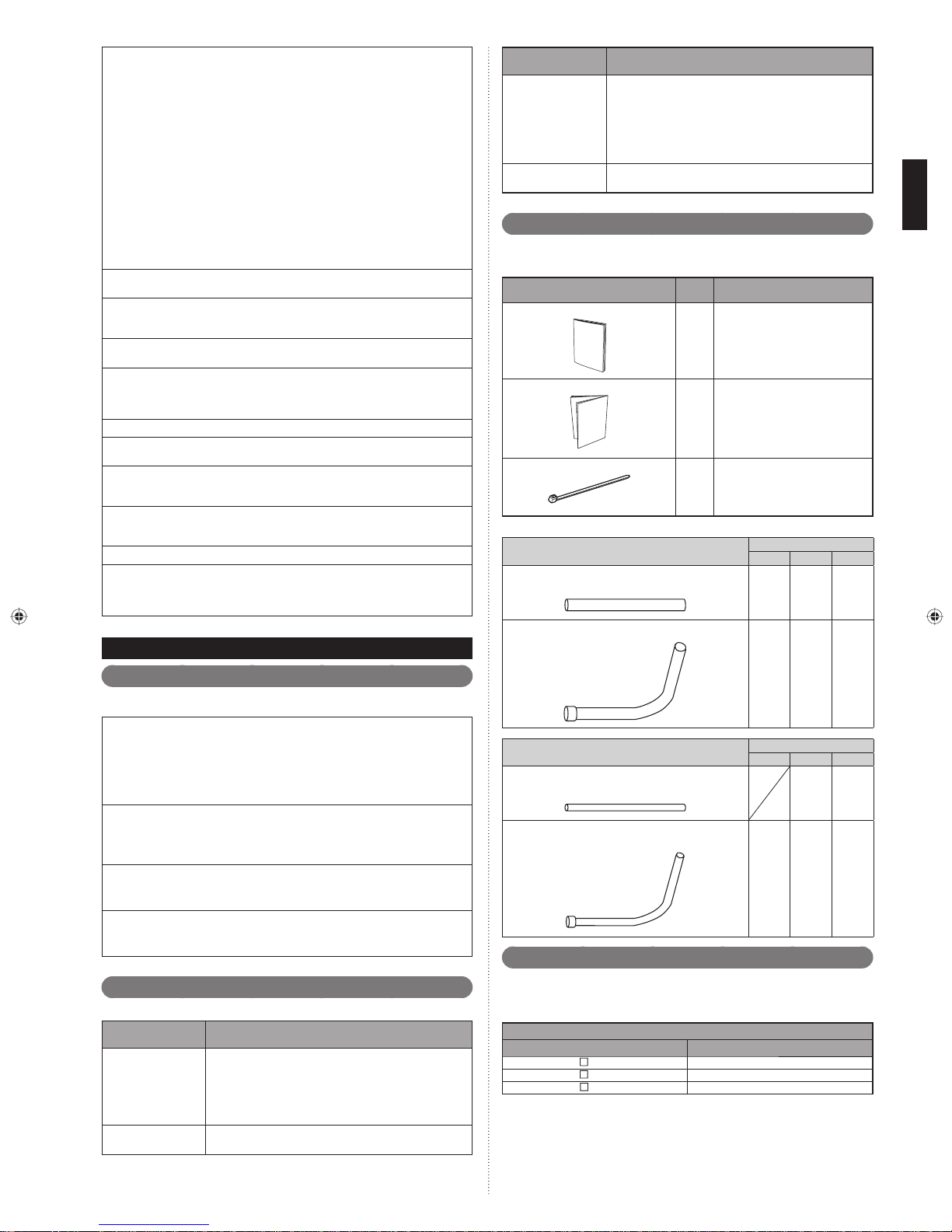
Accessories2. 3.
Use connecting parts as required.
Do not throw away the connecting parts until the installation has been complete.
Name and shape Q’ty Application
Specifi cations manual
Installation manual
cable tie
Joint pipe for Suction gas pipe
Joint pipe A
(Large, Straight type)
Joint pipe B
(Large , L type)
—
1
(This book)
1
For binding power cable and transmission cable
4
Model code
72 90 108
111
111
Pay careful attention to the following points :
Since the working pressure is 1.6 times higher than that of R22 models, some of the
piping and installation and service tools are special. (See the table in the SPECIAL
TOOLS FOR R410A section.)
Especially, when replacing a conventional refrigerant (other than R410A) model
with a new refrigerant R410A model, always replace the conventional piping and
fl are nuts with the R410A piping and fl are nuts.
Models that use refrigerant R410A have a different charging port thread diameter
to prevent erroneous charging with R22, R407C and for safety. Therefore, check
beforehand. [The charging port thread diameter for R410A is 1/2 UNF 20 threads
per inch.]
Be more careful than the installation of the refrigerant (other than R410A) models,
not to enter foreign matters (oil, water, etc.) and other refrigerant into the piping.
Also, when storing the piping, securely seal the openings by pinching, taping, etc.
When charging the refrigerant, take into account the slight change in the composition of the gas and liquid phases, and always charge from the liquid phase side
whose composition is stable.
Special tools for R410A2. 2.
Tool name Contents of change for R22 tool
Pressure is huge and cannot be measured with a conventional (R22) gauge. To prevent erroneous mixing of other
Gauge manifold
Charging hose
refrigerants, the diameter of each port has been changed.
It is recommended to use a gauge manifold with a high
pressure display range -0.1 to 5.3 MPa and a low pressure
display range -0.1 to 3.8 MPa.
To increase pressure resistance, the hose material and
base size were changed.
Joint pipe for Discharge gas pipe
Joint pipe C
(Small , Straight type)
Joint pipe D
(Small , L type)
Model code
72 90 108
11
111
Combinations2. 4.
A maximum of 3 outdoor units can be connected to 1 refrigerant system.
The combination of outdoor units per refrigerant system and the number of indoor units
that can be connected are as follows:
Outdoor Unit
Model Name Nominal System Capacity (HP)
AJ
A72GALH 8
AJ
A90GALH 10
AJ
108GALH 12
En-2
Combination (HP) 8101216182022242628
Outdoor Unit 1 (HP) 8 10 12 8 10 10 12 12 10 10
Outdoor Unit 2 (HP) ---88101012810
Outdoor Unit 3 (HP) --------88
Maximum Connectable Indoor Unit 15 16 17 24 27 30 32 35 39 42
Combination (HP) 30 32 34 36
Outdoor Unit 1 (HP) 10 12 12 12
Outdoor Unit 2 (HP) 10 10 12 12
Outdoor Unit 3 (HP) 10 10 10 12
Maximum Connectable Indoor Unit 45 47 50 53
When connecting outdoor units, install the outdoor unit with the largest nominal system capacity nearest to the refrigerant pipe and indoor unit, followed by those with lesser nominal system
capacities. (Outdoor unit 1 ≥ Outdoor unit 2 ≥ Outdoor unit 3)
Optional parts2. 5.
INSTALLATION WORK3.
Please obtain the approval of the customer when selecting the location of installation
and installing the main unit.
Selecting an installation location3. 1.
WARNING
Install the unit in a location that can withstand its weight, and where it will not topple
or fall.
Calculate the proper refrigerant concentration if you will be installing it in an enclosed location.
Total amount of replenished refrigerant in refrigerant facility (kg)
Capacity of smallest room where unit is installed (m3)
If the results of the calculation exceed the concentration limit, increase the room
surface area or install a ventilation duct.
≤
Refrigerant concentration (kg/m3)
(0.3kg/m3)
CAUTION
The following parts are optional parts specifi c to R410A refrigerant.
Do not use parts other than those listed below.
RB unit2. 5. 1.
RB unit Total cooling capacity of indoor unit (kW)
UTP-RX01AH 8.0 or less
UTP-RX01BH 18.0 or less
UTP-RX01CH 28.0 or less
UTP-RX04BH
*: In case of 2 RB units connected in series (total 8 branches), maximum capacity of
connectable indoor units is up to 56.0 kW.
18.0 or less (for 1 branch)
56.0 or less (Sum total of 4 branches) *
Outdoor unit branch kit2. 5. 2.
Model Total cooling capacity of indoor unit (kW)
UTP-DX567A ALL
Separation tube2. 5. 3.
Model
for 2 pipes for 3 pipes
UTP-AX090A , UTR-BP090X UTP-BX090A 28.0 or less
UTP-AX180A , UTR-BP180X UTP-BX180A 28.1 to 56.0
UTP-AX567A , UTR-BP567X UTP-BX567A 56.1 or more
Total cooling capacity of indoor
unit (kW)
Header2. 5. 4.
Model: for 2 pipes
3-6 branches 3-8 branches
UTR-H0906L UTR-H0908L 28.0 or less
UTR-H1806L UTR-H1808L 28.1 to 56.0
Model: for 3 pipes
3-6 branches 3-8 branches
UTP-J0906A UTP-J0908A 28.0 or less
UTP-J1806A UTP-J1808A 28.1 to 56.0
Total cooling capacity of indoor unit (kW)
Total cooling capacity of indoor unit (kW)
CAUTION
Select an installation location by observing the following precautions:
Install the unit level. (Within 3 degrees)
Install this unit in a location with good ventilation.
If the unit must be installed in an area within easy reach of the general public, install
as necessary a protective fence or the like to prevent their access.
Install the unit in an area that would not inconvenience your neighbors, as they could
be affected by the airfl ow coming out from the outlet, noise, or vibration.
If it must be installed in proximity to your neighbors, be sure to obtain their approval.
If the unit is installed in a cold region that is affected by snow accumulation, snow fall,
or freezing, take appropriate measures to protect it from those elements.
To ensure a stable operation, install inlet and outlet ducts.
Install the unit in an area that would not cause problems even if the drain water is
discharged from the unit. Otherwise, provide drainage that would not affect people or
objects.
Install the unit in an area that has no heat sources, vapors, or the risk of the leakage
of fl ammable gas in the vicinity.
Install the unit in an area that is away from the exhaust or vent ports that discharge
vapor, soot, dust, or debris.
Install the indoor unit, outdoor unit, power supply cable, transmission cable and
remote control cable at least 1 meter away from a television or radio.
The purpose of this is to prevent TV reception interference or radio noise. (Even if
they are installed more than 1 meter apart, you could still receive noise under some
signal conditions.)
Keep the length of the piping of the indoor and outdoor units within the allowable
range.
For maintenance purposes, do not bury the piping.
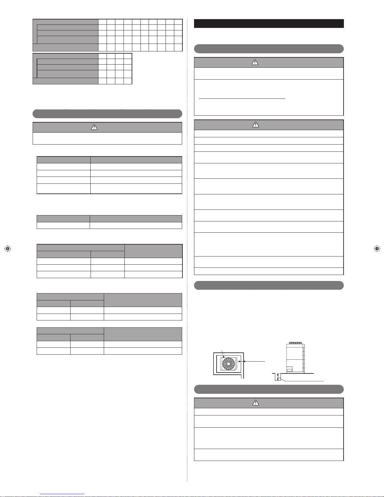
Drain processing3. 2.
The drain water is discharged from the bottom of the equipment. Construct a drain •
ditch around the base and discharge the drain water properly.
When installing on a roof, perform fl oor waterproofi ng properly.•
Drain processing:
The drain water from the base of the outdoor unit may generate during operations.•
Perform drain processing, as necessary.
When you want to prevent the drain water from leaking at the perimeter, construct •
a ditch for the drain water as shown in the fi gure.
Provide a central drain pan, as necessary.•
Outdoor unit
50mm or
more
En-3
10mm or more
Installation dimensions3. 3.
CAUTION
When installing the outdoor unit, pay attention to the following items.
Provide suffi cient installation space, such as transportation route, maintenance
space, ventilation space, refrigerant piping space, and passageways.
Pay attention to the specifi cations of the installation space as shown in the fi gure.
If the unit is not installed according to specifi cations, it may cause short circuit or
poor performance. The unit may be prone to lapse into non-operation due to high
pressure protection.
Do not place obstructions in the air fl ow outlet direction. If there is an obstruction in
the outlet direction, install an outlet duct.
CAUTION
When there is a wall in front of the unit, provide a space of 500mm or more as
maintenance space.
When there is a wall at the left side of the unit, provide a space of 30mm or more
as maintenance space.
An outdoor temperature of 35 degrees in air-conditioned operation is assumed for
the installation space in this item. If the outdoor temperature exceeds 35 degrees
and the outdoor unit is operating at a load exceeding its rated ability, provide a
larger inlet space.
If you are installing more outdoor units than indicated here, please ensure suffi cient
space or consult your distributing agent as it may affect the performance due to
short circuit and other problems.
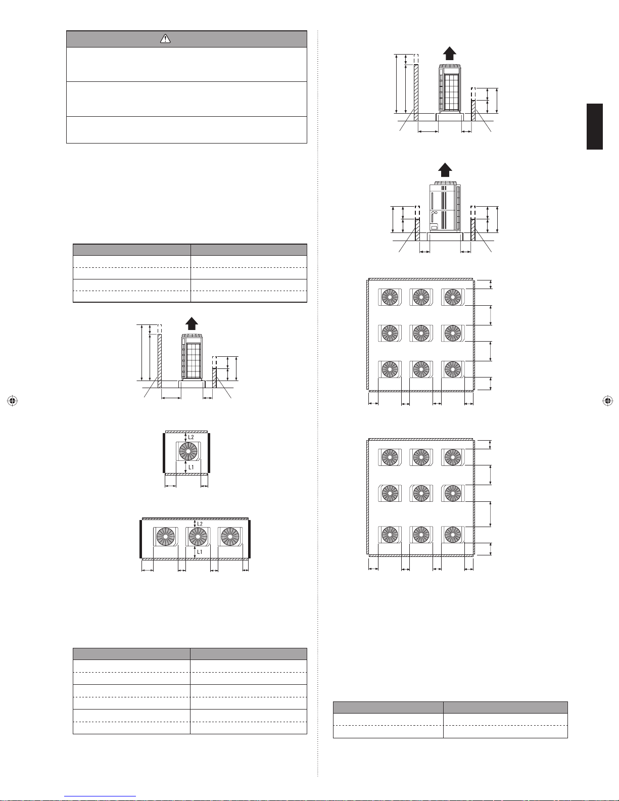
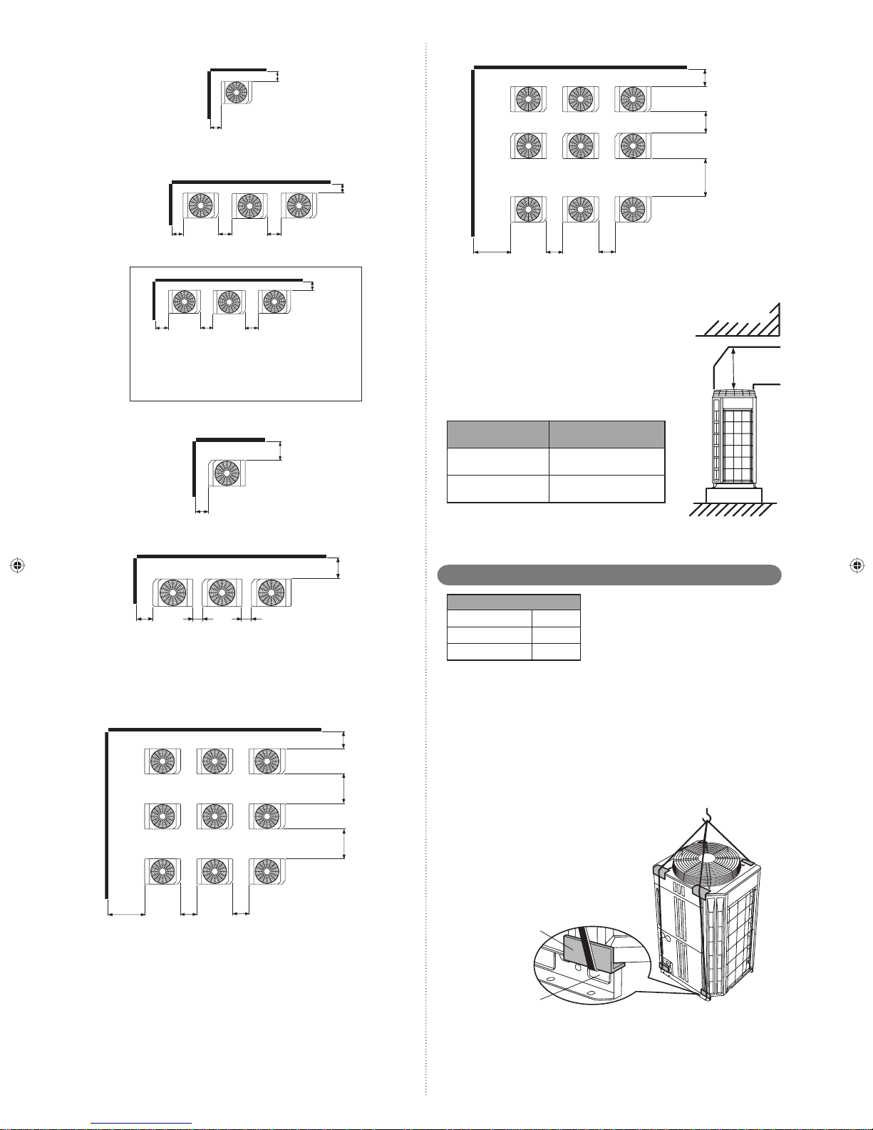
When install near by limited height wall3. 3. 1.
Single and multiple installations(1)
There are no restrictions on the height of the side wall.•
Provide installation spaces L1 and L2 in accordance with the table below according •
to the wall height (front side, rear side) conditions.
Provide installation spaces other than L1 and L2 in accordance with the conditions •
shown in the fi gure below.
Ventilation resistance can be ignorable when the distance from a wall or product, •
etc. is larger than 2m.
Wall height condition Necessary installation space
When H1 is 1500 (mm) or less L1 ≥ 500 (mm)
When H1 is 1500 (mm) or more L1 ≥ 500+h1÷2 (mm)
When H2 is 500 (mm) or less L2 ≥ 100 (mm)
When H2 is 500 (mm) or more L2 ≥ 100+h2÷2 (mm)
1Fig.
<Front> <Rear>
<Side view>
J
4Fig.
<Front>
<Side view>
<Rear>
J
*
J
*
Wall
5 Fig.
H5
.
<Front view>
h5
500
L5
6 Fig.
Wall Wall
<Top view>
.
Wall
h5
H5
500
L5
L4
800mm
or more
*
Wall
2 Single installationFig.
<Front>
3 Multiple installationsFig.
<Rear>
<Front>
30mm or
more
Concentrated installation(2)
Provide installation spaces L3, L4, and L5 in accordance with the table below ac-•
cording to the wall height (front side, rear side) conditions.
Provide installation spaces other than L3, L4, and L5 in accordance with the condi-•
tions shown in the fi gure below.
Ventilation resistance can be ignorable when the distance from a wall or product, •
etc. is larger than 2m.
Wall height condition Necessary installation space
When H3 is 1500 (mm) or less L3 ≥ 500 (mm)
When H3 is 1500 (mm) or more L3 ≥ 500+h3÷2 (mm)
When H4 is 500 (mm) or less L4 ≥ 200 (mm)
When H4 is 500 (mm) or more L4 ≥ 200+h4÷2 (mm)
When H5 is 500 (mm) or less L5 ≥ 200 (mm)
When H5 is 500 (mm) or more L5 ≥ 200+h5÷2 (mm)
.
<Top view>
<Rear>
30mm or more 10mm or more
<Top view>
20mm or
more
.
20mm or
more
J
*
Wall
10mm or
more
800mm
or more
L3
20mm or
7 Fig.
more
20mm or
L5
more
20mm or
more
<Top view>
20mm or
more
L5L5
L4
500mm
or more
1000mm
or more
L3
L5
When install near unlimited height wall3. 3. 2.
Single and multiple installations(1)
There are no restrictions on the height of the wall.•
The wall (without height restrictions) must not exist on the both sides (left / right) •
of outdoor unit. Also, must not exist on the both sides (front / rear) of outdoor
unit.
Provide installation spaces other than L6 in accordance with the conditions •
shown in the fi gure below.
Ventilation resistance can be ignorable when the distance from a wall or prod-•
uct, etc. is larger than 2 m.
When installing with the REAR of the outdoor unit facing the wall side
Condition Necessary installation space
When B ≥ 400 (mm) L6 ≥ 200 (mm)
When 20 ≤ B < 400 (mm) L6 ≥ 200 + (400-B) ×3 (mm)
En-4
8 Single installationFig.
<Rear>
<Top view>
100mm
or more
13Fig.
<Top view>
400mm
or more
<Front>
200mm
or more
9 MFig. ultiple installations
<Rear>
<Front>
200mm
or more
200mm
200mm 200mm
or more
Example :
When B is made 200mm
L6 ≥ 200+(400-200)×3=800mm
When installing with the FRONT of the outdoor unit facing the wall side
10 Fig.
Wall
200mm or more
11 Fig.
Wall
200mm
or more
Concentrated Installation(2)
The wall (without height restrictions) must not exist on the both sides (left / right) of •
outdoor unit. Also, must not exist on the both sides (front / rear) of outdoor unit.
Ventilation resistance can be ignorable when the distance from a wall or product, •
etc. is larger than 2m.
12 Fig.
20mm or
more
B
<Top view>
<Top view>
<Rear>
<Front>
20mm or
more
<Top view>
<Top view>
Wall
B
500mm
or more
Wall
800mm
or more
L6
500mm
or more
400mm
or more
800mm
or more
500mm
or more
1000mm
or more
1000mm
or more
400mm
or more
400mm
or more
When there are obstacles above the product3. 3. 3.
When there are obstacles above the product, keep the
minimum installation height as shown in the fi gure and
install the outlet duct.
When installing the outlet duct, you must set the high
static pressure mode with the push-button switch.
(Similar when installing anti-snow hood)
Setting high static pressure mode
Follow the instructions in the table below to set the high
static pressure mode.
Condition
Static Pressure (SP) *1 :
0 ≤ SP ≤ 30 (Pa)
Static Pressure (SP)
30 < SP ≤ 80 (Pa)
Static pressure is the air fl ow resistance that includes *1.
the discharge duct resistance & the other additional resistance like discharge grill
and so on.
Refer to the section on Push Switch Setting in “Chapter 7 Field Setting”.*2.
High static pressure mode
setting
Set to Mode 1
*1
:
Set to Mode 2
*2
Outlet duct
Transportation the outdoor unit3. 4.
Product mass (kg)
A72GALH 262
AJ
□
AJ
A90GALH 262
□
AJ
108GALH 262
□
Hoisting method
When hanging the outdoor unit and conveying it to installation location, hang the •
unit with rope by passing through the 4 opening holes on bottom of front and rear
side as shown in fi gure.
Use 2 ropes at least 8m long. If used shorter length, it may cause to damage to the •
unit
.
Use the suffi ciently strong rope to bear the unit’s weight.•
Place the protective board or fi ller cloth at the place where the cabinet may come •
into contact with rope to prevent from damages. Without using them, cabinet may
cause to damage or deform.
During the hanging unit, make sure to keep the unit level to prevent from falling.•
To prevent an unit swing accident or falling down of the unit, do not apply any •
impact to the unit when it is hanging.
500mm
or more
1000mm
or more
En-5
400mm
or more
400mm
or more
800mm
or more
protective boards
opening space
Lifting by forklift
When using the forklift to lift the unit, pass the forklift arms through the opening •
space as shown in below.
Front : Bottom of the wooden delivery pallet.
Side : Space between pallet and cabinet.
(Enable to remove the pallet from cabinet.)
Be careful not to damaged.•
Lifting by forklift (Manual forklift: hand-fork)
When using the manual forklift to lift the unit, pass the forklift arms through to the •
opening space between pallet and cabinet from side.
<Front>
Fork (Forklift)
Delivery pallet
<Side>
Fork (forklift) or
Fork (Manual forklift)
Installation the unit3. 5.
Install the unit level. (within 3 degrees).•
Install 4 or more anchor bolts at the 8 locations indicated by arrows (Fig. A).•
Place the left and right anchor bolts at a distance further away than the dimensions •
of A in the Table A.
(Excluding the case where anchor bolts are installed at 8 places.)
AFig.
930
610
(Unit: mm)
160160
CFig.
When installing piping from the bottom
of the outdoor units,
the required space
under the outdoor
unit ≥ 200mm.
* Install the branch
kit horizontally.
SYSTEM CONFIGURATION4.
System confi guration4. 1.
CAUTION
When connecting multiple outdoor units, set the nearest outdoor unit to the indoor •
unit on the refrigerant pipe as the master unit.
When connecting multiple outdoor units, install the outdoor unit with the largest •
nominal system capacity nearest to the indoor unit and on the refrigerant pipe,
followed by those with less nominal system capacities.
Always keep to the limit on the total amount of refrigerant. Exceeding the limit •
on the total amount of refrigerant when charging will lead to malfunction.
In case of 1 outdoor unit connected A)
A Fig.
f
RB
I.U. I.U. I.U. I.U. I.U.
H5
O.U.
(Master)
a
RB RB RB
p
O.U. :Outdoor unit
RB :RB unit
I.U. :Indoor unit
(*1: Cooling only)
*1
H1
More than
200mm
Hole: 12 × 17
(8 places)
To minimize vibration, do not install the outdoor unit directly on the ground.•
Instead, install it on top of a fi rm platform (such as concrete block). (Fig. B)
The foundation base should be able to support the product and the foot width of •
the product should be more than 46.5mm.
Depending on the installation condition, vibration during the operation of the unit •
may cause noise and vibration.
Install vibration-proofi ng materials (such as rubber pads).
Consider the removal space of the connection piping when installing the founda-•
tion.
Secure the equipment fi rmly with anchor bolts, washers, and nuts.•
BFig.
*Do not use a four-corner support foundation.
Bottom view
80
GoodProhibited Good
732
765
80
Bolt (M10)
RB RB RB RB
I.U.I.U.I.U.
H4
H3
Allowable pip length (actual pipe length)•
Between master outdoor unit and the
farthest indoor unit
Between the fi rst separation tube and the
farthest indoor unit
Total pipe length 700 m or less Total
Allowable height difference•
Between outdoor unit and indoor unit (When
indoor unit is installed below)
Between outdoor unit and indoor unit (When
outdoor unit is installed below)
Between indoor units 15 m or less H2, H3
Between RB unit and indoor unit 5 m or less H4
Between RB units 15 m or less H5
Total refrigerant amount : 70 kg or more•
In case of 2 outdoor unit connected B)
B Fig.
O.U.-1
(Master)
e
O.U.-2
(Slave)
H4
a
f
O.U. :Outdoor unit
RB :RB unit
I.U. :Indoor unit
b
165 m or less
60 m or less f, p
50 m or less
40 m or less
(*1: Cooling only)
I.U.
H2
a+f
a+p
H1
RB RB RB RB
I.U. I.U. I.U. I.U. I.U.
H6
RB RB RB RB
p
H1
*1
H2
H5
I.U.I.U.I.U.
H3
I.U.
En-6
Allowable pip length (actual pipe length)•
Between master outdoor unit and the
farthest indoor unit
Between the fi rst separation tube and the
farthest indoor unit
165 m or less
60 m or less f, p
a+e+f
a+e+p
Total pipe length 1000 m or less Total
Between outdoor unit and outdoor unit
branch kit
3 m or less a, b
Allowable height difference•
Between outdoor unit and indoor unit (When
indoor unit is installed below)
Between outdoor unit and indoor unit (When
outdoor unit is installed below)
50 m or less
H1
40 m or less
Between indoor units 15 m or less H2, H3
Between outdoor units 0.5 m or less H4
Between RB unit and indoor unit 5 m or less H5
Between RB units 15 m or less H6
Total refrigerant amount : 70 kg or more•
Outdoor unit capacity : Master ≥ Slave•
In the case of 3 outdoor units connected C)
O.U.-1
(Master)
O.U.-2
(Slave1)
a
d
e
CFig.
RB
I.U.
H6
RB RB RB RB
I.U. I.U. I.U.
O.U.-3
(Slave2)
H4
b
c
RB RB
I.U. I.U. I.U. I.U.
f
O.U. :Outdoor unit
RB :RB unit
I.U. :Indoor unit
(*1:Cooling only)
RB
p
H5
H3
I.U.
H1
*1
H2
Allowable pip length (actual pipe length)•
Between master outdoor unit and the
farthest indoor unit
Between the fi rst separation tube and the
farthest indoor unit
165 m or less
60 m or less f, p
a+e+f
a+e+p
Total pipe length 1000 m or less Total
Between outdoor unit and outdoor unit
branch kit
Between the farthest outdoor unit and the
fi rst outdoor unit branch kit
3 m or less a, b, c
12 m or less
b+d
c+d
Allowable height difference•
Between outdoor unit and indoor unit (When
indoor unit is installed below)
Between outdoor unit and indoor unit (When
outdoor unit is installed below)
50 m or less
H1
40 m or less
Between indoor units 15 m or less H2, H3
Between outdoor units 0.5 m or less H4
Between RB unit and indoor unit 5 m or less H5
Between RB units 15 m or less H6
Total refrigerant amount : 105 kg or more•
Outdoor unit capacity : Master ≥ Slave 1 ≥ Slave 2•
If the outdoor temperature during cooling operation is expected to be –5 °C
• NOTE)
or less, do not install the outdoor unit lower than the indoor unit
• Please refer to “8.3.2. Checking total amount of refrigerant and calculating the amount of refrigerant charge to be added” for the total amount of
refrigerant.
.
Pipe selection4. 2.
CAUTION
This unit is designed specifi cally for use with the R410A refrigerant. Pipes for
R407C or R22 may not be used with this unit. Do not use existing pipes. Improper
pipe selection will degrade performance.
Master
Slave
unit1
Slave
unit2
unit
Pipe size (table A)
Pipe size (table B)
Pipe size (table C)
Pipe size (table E)
Separation tube (Optional)
Pipe size
(table D)
Outdoor unit branch kit (Optional)
(single
RB
type)
RB (multi type)RB
Pipe size (table F)
(Wall thickness and pipe material for each diameter)
Outside Diameter mm
Wall Thick ness*3mm
Material
Allowable tensile stress ≥ 33 (N/mm*1.
Allowable tensile stress ≥ 61 (N/mm*2.
Endurance pressure of the pipes 4.2MPa*3.
Please select the pipe size in accordance with local rules.
6.35 9.52 12.70 15.88 19.05 22.22 28.58 34.92 41.27
0.8 0.8 0.8 1.0 1.2 1.0 1.0 1.2 1.43
JIS H3300 C1220T-O or equiva-
COPPER
lent
2
)
2
)
*1
JIS H3300 C1220T-H or
COPPER
equivalent
*2
A (Between outdoor unit and outdoor unit branch kit)Tab le.
HP
8
10
12
Outdoor
unit cooling
capacity (kW)
22.4 12.70 (1/2") 15.88 (5/8") 22.22 (7/8")
28.0 12.70 (1/2") 19.05 (3/4") 22.22 (7/8")
33.5 12.70 (1/2") 19.05 (3/4") 28.58 (1-1/8")
Outside diameter mm (in)
Liquid pipe
Discharge
Gas pipe
Suction Gas
pipe
Branch kit
UTP-DX567A
*4
For the installation method, refer to “5.4. Multiple connections”.*4.
B (Between outdoor unit branch kits or outdoor unit branch kit and Table.
fi rst separation tube)
Tot al co oling
capacity of outdoor
unit (kW)
Liquid pipe
Outside diameter mm (in)
Discharge Gas
pipe
Suction Gas pipe
22.4 12.70 (1/2") 15.88 (5/8") 22.22 (7/8")
22.5 to 28.0 12.70 (1/2") 19.05 (3/4") 22.22 (7/8")
28.1 to 33.5 12.70 (1/2") 19.05 (3/4") 28.58 (1-1/8")
33.6 to 45.0 12.70 (1/2") 22.22 (7/8") 28.58 (1-1/8")
45.1 to 56.0 15.88 (5/8") 22.22 (7/8") 28.58 (1-1/8")
56.1 to 78.5 15.88 (5/8") 28.58 (1-1/8") 34.92 (1-3/8")
78.6 to 96.0 19.05 (3/4") 28.58 (1-1/8") 34.92 (1-3/8")
96.1 to 102.4 19.05 (3/4") 28.58 (1-1/8") 41.27 (1-5/8")
102.5 or more 19.05 (3/4") 34.92 (1-3/8") 41.27 (1-5/8")
C (Between separation tubes or separation tube and RB unit)Tab le.
Total cooling
capacity of indoor
unit (kW)
Outside diameter mm (in)
Liquid pipe
Discharge Gas
pipe
Suction Gas
pipe
Separation
tube
for 3 pipes
4.4 to 11.1 9.52 (3/8") 12.70 (1/2") 15.88 (5/8")
11.2 to 13.9 9.52 (3/8") 12.70 (1/2") 19.05 (3/4")
14.0 to 22.3 12.70 (1/2") 15.88 (5/8") 22.22 (7/8")
UTP-
BX090A
22.4 to 28.0 12.70 (1/2") 19.05 (3/4") 22.22 (7/8")
28.1 to 44.7 12.70 (1/2") 19.05 (3/4") 28.58 (1-1/8")
44.8 to 46.9 15.88 (5/8") 19.05 (3/4") 28.58 (1-1/8")
47.0 to 56.0 15.88 (5/8") 22.22 (7/8") 28.58 (1-1/8")
56.1 to 80.0 15.88 (5/8") 28.58 (1-1/8") 34.92 (1-3/8")
80.1 to 95.0 19.05 (3/4") 28.58 (1-1/8") 34.92 (1-3/8")
95.1 or more 19.05 (3/4") 28.58 (1-1/8") 41.27 (1-5/8")
* If the selected pipe diameter between separation tubes (based on table "C") becomes
larger than the pipe diameter between outdoor unit branch kit and the fi rst separation
tube (based on table "B"), please select the pipe whose diameter is equal to the one
between outdoor unit branch kit and the fi rst separation tube.
(If pipe diameter C > B, select pipe size from table B)
* Total cooling capacity of indoor unit" is the total value for the cooling capacity of indoor
unit connected downstream.
* Discharge gas pipe size selection : When indoor unit of cooling only type is connected,
it calculates with the value except capacity of cooling only type.
UTP-
BX180A
UTP-
BX567A
En-7
D (Between separation tube and RB unitTab le.
Model code
Cooling capacity of
indoor unit (kW)
)
Outside diameter mm (in)
Liquid pipe
Discharge
Gas pipe
Suction
Gas pipe
07, 09, 12, 14 2.2, 2.8, 3.6, 4.0, 4.5 6.35 (1/4") 9.52 (3/8") 12.70 (1/2")
18, 24, 30 5.6, 7.1, 8.0, 9.0 9.52 (3/8") 12.70 (1/2") 15.88 (5/8")
36, 45, 54 11.2, 12.5, 14.0 9.52 (3/8") 12.70 (1/2") 19.05 (3/4")
60 18.0 9.52 (3/8") 15.88 (5/8") 19.05 (3/4")
72, 90 22.4, 25.0 12.70 (1/2") 19.05 (3/4") 22.22 (7/8")
Use a standard separation tube for pipe branching. Do not use a T tube as it does not
separate the refrigerant evenly.
E (Between separation tubes or RB unit and separation tube)Tab le .
Tot al co oling ca pa ci ty
of indoor unit (kW)
4.4 to 11.1 9.52 (3/8") 15.88 (5/8")
11.2 to 13.9 9.52 (3/8") 19.05 (3/4")
14.0 to 28.0 12.70 (1/2") 22.22 (7/8")
28.1 to 44.7 12.70 (1/2") 28.58 (1-1/8")
44.8 to 56.0 15.88 (5/8") 28.58 (1-1/8")
56.1 to 80.0 15.88 (5/8") 34.92 (1-3/8")
80.1 to 95.0 19.05 (3/4") 34.92 (1-3/8")
95.1 or more 19.05 (3/4") 41.27 (1-5/8")
* If the selected pipe diameter based on table "E" becomes larger than the pipe diameter
based on table "C", please select the pipe whose diameter is equal to the table "C".
Gas pipe of table "E" should be compared with suction gas pipe of table "C."
(If pipe diameter E > C, select pipe size from table C)
* "Total cooling capacity of indoor unit" is the total value for the cooling capacity of indoor
unit connected downstream.
F (Between separation tube and indoor unit or RB unit andTab le.
Model code
Cooling capacity of
Outside diameter mm (in) Separation tube
Liquid pipe Gas pipe for 2 pipes
Outside diameter mm (in)
indoor unit (kW)
Liquid pipe Gas pipe
UTP-AX090A or
UTR-BP090X
UTP-AX180A or
UTR-BP180X
UTP-AX567A or
UTR-BP567X
indoor unit)
07, 09, 12, 14 2.2, 2.8, 3.6, 4.0, 4.5 6.35 (1/4") 12.70 (1/2")
18, 24, 30 5.6, 7.1, 8.0, 9.0 9.52 (3/8") 15.88 (5/8")
36, 45, 54 11.2, 12.5, 14.0 9.52 (3/8") 19.05 (3/4")
60 18.0 9.52 (3/8") 19.05 (3/4")
72, 90 22.4, 25.0 12.70 (1/2") 22.22 (7/8")
G (Separation tube / Header)Tab le .
Separation tube•
Total cooling capacity
of indoor unit (kW)
Separation tube
for 2 pipes for 3 pipes
*5
28.0 or less UTP-AX090A or UTR-BP090X UTP-BX090A
28.1 to 56.0 UTP-AX180A or UTR-BP180X UTP-BX180A
56.1 or more UTP-AX567A or UTR-BP567X UTP-BX567A
Header•
*5
Total cooling
capacity of indoor
unit (kW)
for 2 pipes for 3 pipes
3-6 Branches 3-8 Branches 3-6 Branches 3-8 Branches
Header
28.0 or less UTR-H0906L UTR-H0908L UTP-J0906A UTP-J0908A
28.1 to 56.0 UTR-H1806L UTR-H1808L UTP-J1806A UTP-J1808A
For the installation method, refer to the section on "Indoor unit pipe connections" *5.
below.
Protection of pipes4. 3.
Protect the pipes to prevent the entry of moisture and dust.•
Especially pay attention when passing the pipes through a hole or connecting the •
end of a pipe to the outdoor unit.
Location Working period
Outdoor
Indoor
1 month or more Pinch pipes
Less than 1 month Pinch or tape pipes
—
Protection method
Pinch or tape pipes
PIPE INSTALLATION5.
Brazing5. 1.
CAUTION
If air or different type of refrigerant enters
the refrigeration cycle, the internal pressure in the refrigeration cycle will become
abnormally high and prevent the unit from
exerting its full performance.
Apply nitrogen gas while brazing the
pipes.
Nitrogen gas pressure: 0.02 MPa (= suffi cient pressure to be felt on the back of
your hand or more)
If a pipe is brazed without applying nitrogen gas, it will create an oxidation fi lm.
This can degrade performance or damage the parts in the unit (such as the compressor or valves).
Do not use fl ux to braze pipes. If the fl ux is the chlorine type, it will cause the pipes
to corrode.
In addition, if the fl ux contains fl uoride, it will affect the refrigerant piping system due to
deterioration of refrigerant oil.
For brazing material, use phosphor copper that does not require fl ux.
Fig.
Pressure regulating valve
Cap
Nitrogen gas
Brazing area
Indoor unit pipe connections5. 2.
CAUTION
For details, refer to the Installation Instruction Sheet of each part.
Separation tube
Horizontal
B
A
B
Vertic al
A
or
Good
Horizontal line
B
A
± 15°
A : Outdoor unit or Refrigerant branch kit
B : Indoor unit or Refrigerant branch kit
Prohibited
Header
Gas pipe
Outdoor
unit side
Liquid pipe
Outdoor
unit side
C
D
Good
A2
2
H
Horizontal line
A
1
1
H
Horizontal
line
B
1
VIEW C
Horizontal
line
B2
VIEW D
Horizontal
line
H1 = 0 to 10 mm
1 : 0o – 1o)
(A
B
1: -10o – 10o
= 0 to 10 mm
H
2
(A
2 : 0o – 1o)
: -10o – 10o
2
B
Prohibited Prohibited
CAUTION
Do not connect a separation tube after a header.
Leave the distance 0.5 m or more for straight part to branch tube and
header.
En-8

Main pipe
Main pipe
0.5 m or more
0.5 m or more
To in do or u ni t
0.5 m or more
To in do or u ni t
0.5 m or more
Separation tube
or
Header
To in do or u ni t
Separation tube
or
Header
To in do or u ni t
To in do or
unit
To in do or
unit
Piping method5. 3.
Opening the knockout hole5. 3. 1.
CAUTION
Be careful to prevent panel deformation or damaged while opening the knockout
hole.
To prevent cutting of the wiring after the knockout hole was opened, remove the
burrs along the edge.
In addition, to prevent rusting, painting the edge with rust preventive paint is recommended.
Removing the pinch pipe5. 3. 2.
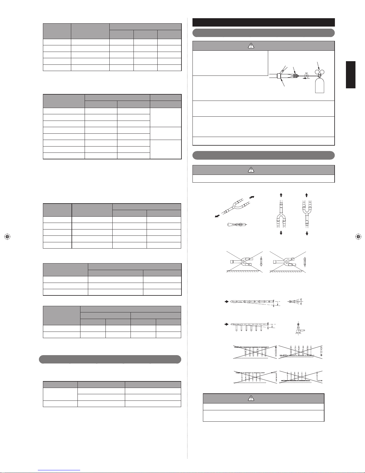
WARNING
Remove the pinch pipe only when the internal gas is completely drained as shown
on the below instructions.
If gas still remains inside, the piping may crack if you melt the brazing fi ller metal of
the junction area with a burner.
Before connecting the piping, remove the pinch pipe in accordance with the following
instructions:
Verify that the liquid side , suction gas side and discharge gas side 3-way valves 1)
are closed.
3-way valves
Cut the end of the liquid side , suction gas side and discharge gas side pinch pipe 2)
and vent the gas inside the pinch pipe.
The piping can be connected from 2 directions; the front or the bottom.
(Knockout holes are provided so that the piping can be connected from 2 different
directions.)
Use the front knockout hole, as required.
A Knockout positionFig.
B Detail of knockout position (bottom)Fig.
80
82
C Detail of knockout position (front)Fig.
(Unit: mm)
Knockout hole
197
42
(Unit: mm)
End of pinch pipe
After all the gas is vented, melt the brazing fi ller metal on connecting part using a 3)
torch and remove the pinch pipe.
95
75
10
100
Knockout
hole
125
4373199
En-9
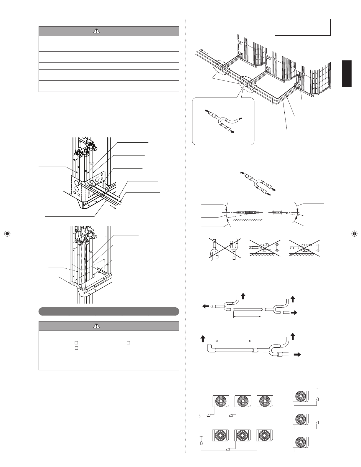
Pipe connection5. 3. 3.
CAUTION
Seal the pipe route hole with putty (fi eld supply) such that there are no gaps.
Small insects or animals that are trapped in the outdoor unit may cause a short circuit
in the electrical component box.
To prevent pipe damage; do not make sharp bends.
Bend the pipe at a radius of 70mm or greater.
Do not bent pipe many times at same part to prevent break.
After completing all the pipe connection by brazing, perform the indoor unit pipe connection with a fl are joint.
When removing the pinch pipe or brazing the joint pipe, carry out the work while
cooling down the 3-way valve suffi ciently.
To in do or u ni t
Outdoor unit
branch kit
(Optional)
Outdoor unit 1
(Master unit)
Outdoor Capacity
2 Unit : Unit 1 ≥ Unit 2
3 Unit : Unit 1 ≥ Unit 2 ≥ Unit 3
Outdoor unit 2
(Slave unit 1)
Outdoor unit 3
(Slave unit 2)
Braze the joint pipe onto the 3-way valves at the liquid , suction gas and discharge •
gas side.
Install the joint pipe appropriately so that it can be connected easily with the main
pipe.
Braze the joint pipe at the liquid , suction gas and discharge gas side with the main •
pipe.
* Be sure to supply nitrogen when brazing.
AFig.
Joint pipe
(Field supply)
Liquid pipe
(Field supply)
BFig.
Joint pipe
(fi eld supply)
Joint pipe D
(Accessories)
Joint pipe B
(Accessories)
Knockout hole
Suction gas pipe
(Field supply)
Discharge gas pipe
(Field supply)
To RB unit or indoor unit
Joint pipe C
(Accessory or fi eld supply) *1
Joint pipe A
(Accessory or fi eld supply) *1
Knockout hole
*1) Field supply and accessory
depend on the model, so for
details, refer "2.3. Accessories".
To in do or u ni t
(To main pipe)
To ou td oor un it
To ou td oor un it
Branch kit restriction when install
Be sure following restriction.
Installation angle 1)
Outdoor unit branch kit
Horizontal
A
To in do or u ni t
Prohibited
Good:
0° to -10°
Prohibited
Vert ical
Prohibited Prohibited Prohibited
Install the outdoor unit branch kit horizontally level, within 0° to -10°, so that the •
refrigerant separates evenly.
Do not install the outdoor unit branch kit vertically.•
Straight pipe length 2)
To in do or u ni t
(To main pipe)
A
To ou td oor un it
Liquid pipe
(Field supply)
C
Discharge gas pipe
(Field supply)
Suction gas pipe
(Field supply)
To ou td oor un it
B
To outdoor unit or
C
next branch kit
C
B
Joint pipe
(Accessory)
Prohibited
Good:
0° to -10°
Prohibited
To ou td oor un it
Multiple connections5. 4.
CAUTION
When connecting multiple (maximum 3) units, be sure to install the unit with the •
largest capacity nearest to the indoor unit.
For example) AJ
When connecting multiple units, set the unit with the largest capacity as the master •
unit, and the rest as the slave units.
(Refer to 7. Field Setting)
When connecting multiple units, use the optional outdoor unit branch kit.•
108GALH (Outdoor Unit1) + AJ A90GALH (Outdoor Unit2) +
AJ
A72GALH (Outdoor Unit3)
0.5 m or more
To indoor unit (To main pipe)
0.5 m or more
Leave the distance 0.5 m or more for straight part to outdoor unit branch kit.•
For details, refer to the Installation Instruction Sheet of the outdoor unit branch kit. 3)
Examples of multiple unit installationFig.
(Example 1)
Master unit Slave unit1 Slave unit2
(Example 2)
Master unit Slave unit1 Slave unit2
To ou td oor un it
(Example 3)
Master
unit
Slave
unit1
Slave
unit2
To ou td oor un it
To ou td oor
unit
En-10
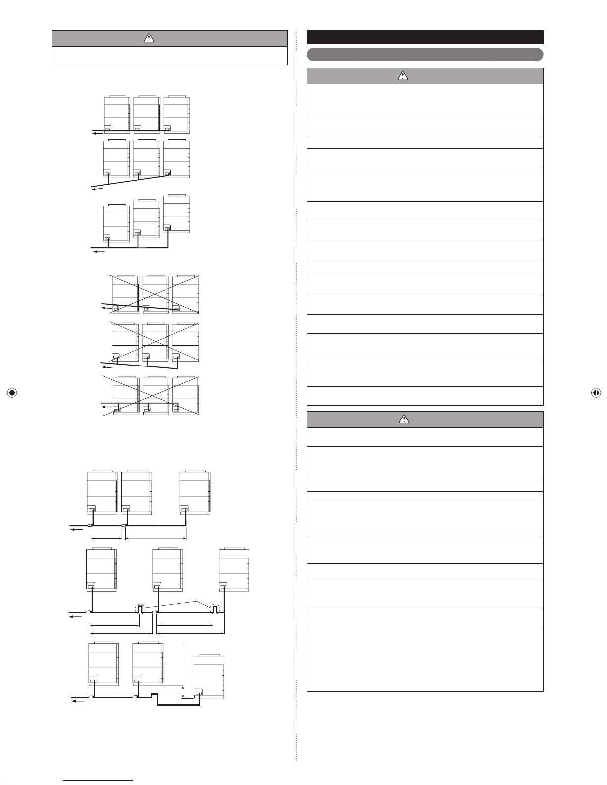
CAUTION
To prevent the oil from settling in the stopped unit, install the pipes between the
outdoor units so that they are level or are tilted upward to the outdoor units.
ELECTRICAL WIRING6.
The precautions of electrical wiring6. 1.
Examples of multiple unit installation are shown below.(1)
Installable patterns a)
Good
To in do or u ni t
Good
To in do or u ni t
Good
To in do or u ni t
Non-installable patterns b)
Prohibited
To in do or u ni t
Prohibited
To in do or u ni t
Prohibited
To in do or u ni t
Master
unit
Master
unit
Master
unit
Master
Master
Master
unit
unit
unit
Slave
unit 1
Slave
unit 1
Slave
unit 1
Slave
unit 1
Slave
unit 1
Slave
unit 1
Slave
unit 2
Slave
unit 2
Slave
unit 2
Slave
unit 2
Slave
unit 2
Slave
unit 2
WARNING
Wiring connections must be performed by a qualifi ed person in accordance with
specifi cations.
The rated supply of this product is 50Hz, 400V of 3-phase, 4-wire. Use a voltage
within the range of 342-456V.
Make sure to perform earthing (grounding) work. Improper earthing (grounding) work
can cause electric shocks.
Before connecting the cables, make sure the power supply is OFF.
Be sure to install an earth (ground) leakage breaker. Otherwise, it will cause electric
shock or fi re.
Be sure to install a breaker of the specifi ed capacity. When selecting breaker, please
comply with the laws and the regulations of each country. One breaker must be
installed on the power supply of the outdoor unit. Wrong selection and setup of the
breaker will cause electric shock or fi re.
Do not connect AC power supply to the transmission line terminal board.
Improper wiring can damage the entire system.
Connect the connector cord securely to the terminal.
Faulty installation can cause a fi re.
Do not modify power cable, use extension cable or branch wiring. Improper use may
cause electric shock or fi re by poor connection, insuffi cient insulation or over current.
Make sure to secure the insulation portion of the connector cable with the cord
clamp. A damaged insulation can cause a short circuit.
Never install a power factor improvement condenser. Instead of improving the power factor,
the condenser may overheat.
Before servicing the unit, turn the power supply switch OFF. Then, do not touch electric parts for 10 minutes due to the risk of electric shock.
Always use a separate power supply line protected by a circuit breaker operating on
all cables with a distance between contact of 3 mm for this unit.
Use crimp-type terminals and tighten the terminal screws to the specifi ed torques,
otherwise, abnormal overheating may be produced and possibly cause serious damage inside the unit.
Securely install the electrical box cover on the unit. An improperly installed service
panel can cause serious accidents such as electric shock or fi re through exposure to
dust or water.
If the supply cable is damaged, it must be replaced by the manufacturer, its service
agent or similarly qualifi ed persons in order to avoid a hazard.
If the pipe length between outdoor unit branch kit and outdoor unit branch kit (or (2)
slave unit) is longer than 2 m, or a lower pipe line exists between outdoor units,
rise for gas pipe (Discharge gas pipe and Suction gas pipe) should be arranged
to eliminate oil from entering into and remaining at pipes and the stopped outdoor
unit. However, there is no need to provide a rise on the pipe connecting between
the master unit and the indoor unit even if the length exceeds 2m.
To in do or u ni t
To in do or u ni t
To in do or u ni t
Master
unit
Master
unit
2 m or less 2 m or less
Master
unit
Slave
unit 1
2 m or less2 m or less
2 m or more 2 m or more
Slave
unit1
unit 2
Slave
unit1
(200 mm or more)
500 mm or less
Rise
lower pipe
Slave
Suction gas pipe
Discharge gas pipe
Rise
Slave
unit2
Suction gas pipe
Discharge gas pipe
Slave
unit2
Suction gas pipe
Discharge gas pipe
CAUTION
The primary power supply capacity is for the air conditioner itself, and does not include the
concurrent use of other devices.
Connect the power cables in positive phase sequence. If they are connected in
negative phase sequence, an error will be displayed. If there is a missing phase connection, the unit will not operate normally. Do not connect a N phase (neutral phase)
cable to other phases (misconnection). Wrong wiring will lead to parts damage.
Do not use crossover power supply wiring for the outdoor unit.
If the electrical power is inadequate, contact your electric power company.
Install a breaker (Included with earth leakage circuit breaker) in a location that is not
exposed to high temperatures.
If the temperature surrounding the breaker is too high, the amperage at which the
breaker cuts out may decrease.
Use a breaker (Included with earth leakage circuit breaker) that is capable of handling
high frequencies. Because the outdoor unit is inverter controlled, a high-frequency
breaker is necessary to prevent a malfunction of the breaker itself.
When the electrical switchboard is installed outdoors, place it under lock and key so
that it is not easily accessible.
Never bundle the power supply cable and transmission cable, remote control cable
together. Separate these cable by 50 mm or more. Bundling these cables together
will cause miss operation or breakdown.
Always keep to the maximum length of the transmission cable. Exceeding the maximum length may lead to erroneous operation.
The static electricity that is charged to the human body can damage the control PC
board when handling the control PC board for address setting, etc.
Please keep caution to the following points.
Provide the earthing (grounding) of Indoor unit, Outdoor unit and Option equipment.
Cut off the power supply (breaker).
Touch the metal section (such as the unpainted control box section) of the indoor or
outdoor unit for more than 10 seconds. Discharge the static electricity in your body.
Never touch the component terminal or pattern on the PC board.
En-11
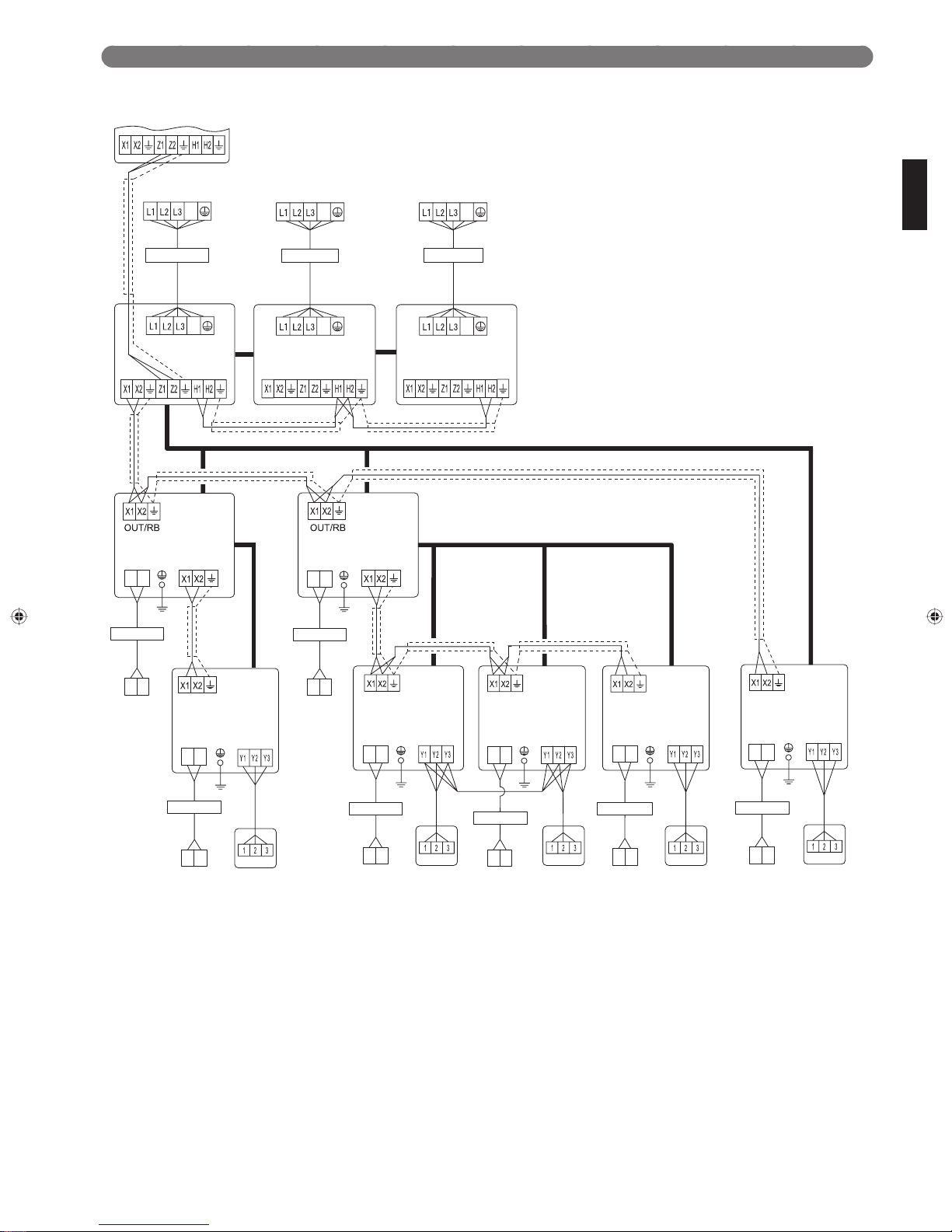
Wiring method6. 2.
The wiring example for RB units ,outdoor units and indoor units is shown in the fi gure.
To other refrigerant cricuit
outdoor unit
Power supply
400V 3Ø 50Hz
N
Breaker Breaker Breaker
Outdoor unit 1
(Master unit)
N
Power supply
Transmission Transmission Transmission
RB unit
Power
supply
L
N
Breaker Breaker
IN/U
Power supply
400V 3Ø 50Hz
N
Outdoor unit 2
(Slave unit 1)
N
Power supply Power supply
Power supply
400V 3Ø 50Hz
N
N
RB unit
Power
supply
L
N
IN/U
Outdoor unit 3
(Slave unit 1)
(*1:Cooling only)
Refrigerant piping
*1
Power
supply
L
N
Breaker
L
N
Transmission
Indoor unit
L
N
Power supply
230V 1Ø 50Hz
Power supply
230V 1Ø 50Hz
There are two types of remote controller: the 2-wire type and the 3-wire type. For details, see the relevant remote controller installation manual. (When connecting the 2-wire type •
remote controller, Y3 is not used.)
Remote
control
Remote
control unit
L
N
Power supply
230V 1Ø 50Hz
Power
supply
L
N
Breaker
L
N
Power supply
230V 1Ø 50Hz
Transmission Transmission Transmission Transmission
Indoor unit Indoor unit Indoor unit Indoor unit
Remote
control
Remote
controller
Power
supply
L
N
Breaker
L
N
Power supply
230V 1Ø 50Hz
Remote
control
Remote
controller
Power
supply
L
N
Breaker
L
N
Power supply
230V 1Ø 50Hz
Remote
control
Remote
controller
Power
supply
L
N
Breaker
L
N
Power supply
230V 1Ø 50Hz
Remote
control
Remote
controller
En-12
Knockout hole6. 3.
CAUTION
Seal the wiring route hole with putty (fi eld supply) such that there are no gaps.
Small insects or animals that are trapped in the outdoor unit may cause a short circuit
in the electrical component box.
Be careful not to deform or scratch the panel while opening the knockout holes.
After opening the knockout hole, remove the burr on the edges to prevent snapping
of cables.
It is recommended to apply rust proof paint on the edges to prevent rust.
Electric wires can be connected from the front or from the left.
(Knockout holes are prepared so that wiring can be made from 2 different directions.)
Use the knockout holes on the front and the left separately when necessary.
< Left view >
Ø 50
Ø 34.5
Ø 43.7
Ø 22.2
< Front view >
Ø 50
Ø 34.5
Ø 22.2
Ø 43.7
(Unit: mm)
In case of connected outdoor unitFig.
Transmission cable
Good
400 V 3ø 50 Hz
Breaker
Outdoor unit
power supply cable
Selecting main breaker and main power supply cable when connecting multiple (2)
outdoor units
Main breaker: Main breaker ≥ Tota l S ub brea ke r
sub breaker capacity)
In case of connected 3 outdoor unitFig.
Good
Main
breaker
400 V 3ø
50 Hz
Example of bad breaker wiring(3)
Prohibited
230 V 1ø 50 Hz
230 v 1ø 50 Hz
Remote controller cable
Sub
breaker
Outdoor unit power supply cable
RB unit
power supply
cable
Breaker
Indoor unit
power supply
cable
(Refer to the table in item (1) for the
Selecting power supply cable and breaker6. 4.
CAUTION
Obtain the distribution network operator's agreement about the power capacity of
the power supply system, specifi cation of the cable and the harmonic current, and
etc. when you connect the outdoor unit with the power supply.
Regulation of wire size and circuit breaker differs from each locality, please refer in
accordance with local rules.
Refer to the table for the wiring and breaker specifi cations of each installation condition
Selecting power supply cable and breaker when connecting 1 outdoor unit(1)
MODEL
A72GALH 20
AJ
A90GALH 25
AJ
108GALH 25
AJ
MODEL
AJ
A72GALH 4 4 51
AJ
A90GALH 6 6 62
108GALH 6 6 62
AJ
These values are recommended data. 1)
Specifi cation: Use conformed cord with Type 60245 IEC66 2)
Max. wire length: Set a length so that the voltage drop is less than 2%. Increase 3)
the wire diameter when the wire length is long.
Breaker (Time delay fuse or circuit capacity)
Fuse capacity (A) Leakage current
100mA
0.1sec or less
Outdoor unit power supply cable
Power supply
cable (mm
Ground wire (mm2)
2
)
Critical wiring
length (m)
400 V 3ø
50 Hz
Outdoor unit
Power supply cable
Breaker
Prohibited: install a breaker
for each outdoor unit
.
Transmission line6. 5.
Prohibited: crossover power
supply wiring prohibited
CAUTION
Caution when wiring cable•
When stripping off the coating of lead wire, always use the exclusive tool such as
a wire stripper. If there is no exclusive tool available necessarily, carefully strip the
coating by a cutter etc. so that the conductive wire is not damaged.
If it is damaged, it may lead to an open circuit and a communication error.
Pay attention to the following points while attaching wires on the terminal board.•
Do not attach 2 wires on one side.
Do not twist wires.
Do not cross the wires.
Do not shorted at edge at root.
2pcs at one side
Prohibited
Shorted at edge
Shorted at root
Wires twisted
Prohibited
1 wire
Good
2 wires
En-13
Good
Prohibited Prohibited
Transmission wiring specifi cations6. 5. 1.
Follow the specifi cations below for the transmission cable.
Use Size Wire type Remarks
Transmission
cable
0.33mm
22AWG LEVEL 4 (NEMA)
2
non-polar 2core, twisted pair
solid core diameter 0.65mm
LONWORKS
®
patible cable
Wiring rules6. 5. 2.
Basic wiring rules(1)
Total transmission line length: MAX 3600 m (A+C+D+E+F+G+H+J+K+N+W ≤ 3600)
Transmission line length between each unit : MAX 400 m
Transmission line length between outdoor units in a refrigerant system MAX 18 m (L
≤ 18 m , M ≤ 18 m)
Be sure to set 1 terminal resistor in a network segment..
N
Transmission line
A (a t o b)
E
W
System controller
J
Terminal registor
K
M
L
(a)
D
C
com-
The transmission cable connects indoor units belonging to the same RB group. The
transmission cable cannot be used to connect indoor units belonging to different RB
groups.
Transmission line
Refrigerant pipe
RB group1 RB group1RB group 2 RB group 2
Good Prohibited
Transmission line
Refrigerant pipe
RB unit
(multi type)
RB
group1
If there are more than 321 units(*1) within the network system, a signal amplifi er •
(with the fi lter mode: on) must be installed between the master outdoor units. See
the Signal Amplifi er Installation Manual and Design & Technical Manual for more
information.
RB
group 2
Good
RB
group 3,4
RB
group1
RB
group 2
Prohibited
RB unit
(multi type)
RB
group 3,4
RB unit
H
Indoor unit
(b)
G
F
In the following cases, Signal Amplifi er is required.(2)
When the total length of the transmission line exceeded 500 m
(A+C+D+E+F+G+H+J+K+N ≥ 500 m)
When the total number of unit is over 64.
NS 1
N
P (a to c)
E
(b)
Q (c to b)
F
J
Terminal resistor
NS 3
K
(a)
C
D
H
G
*P+C+D+E+J+K+N ≤ 500 m, Q+F+G+H ≤ 500 m
Touch panel controller
NS 2
W
(c)
Signal amplifi er
Signal Amplifi er
(Filter mode: on)
Unit* means indoor unit, outdoor unit, Touch Panel Controller and System Con-*1)
troller, Signal Amplifi er, single split adaptor, Network Convertor etc..
Do not use loop wiring. This may lead to parts damage and erroneous operation.
Enabling/Disabling automatic address setting6. 5. 3.
You can enable/disable automatic address setting for the indoor unit, RB unit and the
signal amplifi er.
To enable automatic address setting for the indoor unit, connect the indoor unit to
outdoor units under the same refrigerant system.(Fig.4)
Example : Disable Automatic Address setting
Refrigerant
system 1
Refrigerant
system 2
Transmission line
Transmission line
Example : Enable Automatic Address setting
Refrigerant
system 1
Refrigerant
system 2
Transmission line
Transmission line
En-14
Wiring procedure6. 6.
• Remove the cover of the electrical compartment and follow the terminal plate to connect the electric cables to the terminal.
• After connecting the cables, secure them with the cable ties.
• Connect the cables without applying excessive tension.
Cable routing
Secure with a binder as shown in the fi gure below.
(1) Connecting the power supply cable
Caution when wiring cable
1) Use crimp-type terminals with insulating sleeves as shown in the fi gure to con-
nect to the terminal block.
2) Securely clamp the crimp-type terminals to the cables using an appropriate tool
so that the cables do not come loose.
3) Use the specifi ed cables, connect them securely, and fasten them so that there
is no stress placed on the terminals.
4) Use an appropriate screwdriver to tighten the terminal screws. Do not use a
screwdriver that is too small, otherwise, the screw heads may be damaged and
prevent the screws from being properly tightened.
5) Do not tighten the terminal screws too much, otherwise, the screws may break.
6) See the table for the terminal screw tightening torques.
Connecting the
power supply
cable
Connecting the
transmission
cable
Cable tie
Cable guide
Cable clip
Cable tie
(accessory)
Power supply
cable routing
Transmission cable routing
Connecting cables to the terminals
WARNING
Use ring terminals and tighten the terminal screws to the specifi ed torques, other-
wise, abnormal overheating may be produced and possibly cause heavy damage
inside the unit.
Be sure fi ll the holes of power supply cable and transmission cable with putty (fi eld
supply).
If small animals such as insects enter the electrical component box, a short circuit
may be caused.
Strip 10 mm
Ring terminal
Sleeve
Cable
Screw with
special washer
Ring terminal
Screw with
special washer
Ring terminal
Terminal block
Cable
Ring terminal: M8
Earth (Ground)
cable
Cable clamp
90 to 100 mm
70 to 80 mm
Use a ring terminal to connect the electric cables to the power supply terminal *
board.
(2) Connecting the transmission cable
Sealing transmission cable
Connect both ends of the sealed wires of the transmission cable to the earth terminal
of the equipment or to the earth screw near the terminal.
Be very careful that the screws are not overly tightened as the wires may snap and
the terminal may be damaged.
Wind with insulation tape to
prevent short circuit
Tightening to rque
M3 screw 0.5 to 0.6 N·m (5 to 6 kgf·cm)
M8 screw 5.0 to 7.0 N·m (50 to 70 kgf·cm)
En-15
Use one side of the
twisted-pair cable
Be sure to use one side of a twisted-pair cable when using transmission cable with 2
sets of twisted-pair cables.
8 to 10 mm
40 mm or more
Connect both ends of sealed
cable to earth.
Cable clip
Cable tie
IN
RB
External input and external output6. 7.
Terminal position6. 7. 1.
Input 5
CN135
(ORANGE)
Outdoor unit PC board
CN115
Do not bundle the cable for base heater with other cables.
(Example)
In case of Outdoor unit
Insert the connector to CN134 (Red) and CN135 (Orange) of control PC board. (1)
Fix it to the wire with the attached cable tie.(2)
CN135
(Orange)
CN115
(Black)
Clamp
Input 4 Input 3 Input 1 Output 1
CN134
(RED)
(BLACK)
CN133
(WHITE)
CN131
(YELLOW)
CAUTION
CN136
(BLACK)
Clamp
CN134
(Red)
Cable tie
(Accessories)
Output 2
CN137
(BLUE)
Input 1
CN131
(Yellow)
P. C .B
connected unit
Operation behavior
Each input terminal works as follows.
Connector Input signal Status
Input 1
CN131 (Yellow)
Input 3
CN133 (White)
Input 4
CN134 (Red)
Input 5
CN135 (Orange) *3
Slave unit can connect only input5 (CN135).
The operations of each input terminal and the selection of function are set with the
push button on the PC board of outdoor unit. About the setting, please refer to 7.4.
Push button setting.
Note :
*1: Batch stop or Emergency stop pattern can be selected by outdoor unit PC
board push button.
*2: The emergency stop function mounted in the V-II does not guarantee the
regulations of each country. For this reason, suffi cient checking is necessary
regarding use.
Especially, since the fact that the equipment may not be emergency-stopped
in the case of breaking of the wiring to the external input terminals and communication line, communication error due to noise, VRF external input circuit
trouble, etc. must be considered, the provision of double measures that add
direct interruption of the power supply by switch, etc. is recommended as a
precaution.
*3: Pulse input to CN135 must be width 50ms or more, and must be interval 50ms
or more.
OFF Normal operation
OFF Normal operation
OFF Normal operation
No pulse
Pulse
Input 3
CN133
(White)
connected unit
ON Low noise mode operation
Outdoor unit operation peak
ON
control
Batch stop or Emergency stop
ON
operation *1, *2
No information from electricity
meter
Power usage information from
electricity meter
Input 4
CN134
(Red)
connected unit
Input 5
CN135
(Orange)
connected unit
Outdoor unit
Master Slave
O
O
O
OO
°
°
°
External output terminal6. 7. 3.
Service parts : EXTERNAL INPUT WIRE A (9368777005)
You can detect the operation condition of outdoor unit and the abnormal situation •
of both indoor and outdoor unit.
The external output terminal is only valid for Master Unit.•
Wiring method and specifi cations
Error status (Master unit only)
This output indicates the outdoor unit and connected indoor unit's "Normal" or "Error"
status.
Operation status (Master unit only)
This output indicates the outdoor unit's "Operation" status.
Wire
▪ Do not clamp the base heater cable.
External input terminal6. 7. 2.
Service parts: EXTERNAL INPUT WIRE A (9368777005)
Setting to low noise mode, outdoor unit operation peak control setting, emergency/•
batch stop and electricity meter pulse are possible from the outside.
Except for wattmeter pulse reception (CN135) among external input terminals, only •
the Master unit is effective.
Wiring method and specifi cations
A twisted pair cable (0.33 mm*
cable is 150 m.
Use an external input and output cable with appropriate external dimension, de-*
pending on the number of cables to be installed
For each input, pin No.1 is of positive polarity and pin No.2 is of ground level.*
2
(22AWG)) should be used. Maximum length of
Connector Output voltage Status
CN136 (Black)
CN137 (Blue)
0 V Normal
DC 12 to 24 V Error
0 V Stop
DC 12 to 24 V Operation
En-16
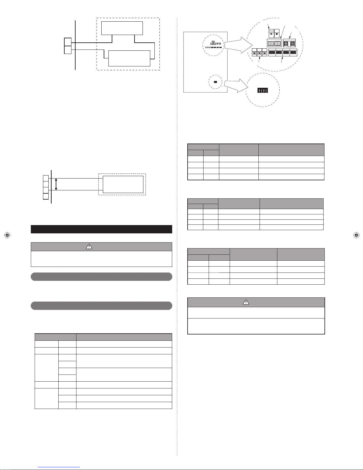
CN136
(Black)
or CN137
(Blue)
P. C .B
+
1
2
*7
DC power supply
(External) 12 to 24 V
+ -
Connected load
(Operation Indicator or
Error Indicator)
*5
*6
connected unit
5: Provide a DC12 to 24 V power supply. *
Select a power supply capacity with an ample surplus for the connected load.
6: The allowable current is 30 mA or less. *
Provide a load resistance such that the current becomes 30 mA or less.
7: Polarity is [+] for pin 1 and [-] for pin 2. Connect correctly.*
Do not impress a voltage exceeding 24 V across pins 1-2.
2
A twisted pair cable (0.33 mm*
cable is 150 m.
Use an external input and output cable with appropriate external dimension, de-*
pending on the number of cables to be installed.
(AWG22)) should be used. Maximum length of
Base heater terminal6. 7. 4.
Service parts : WIRE WITH CONNECTOR (9708642000)
This is the output signal for base heater. Output signal ON, when the outdoor temperature goes down below 2°C, and signal OFF at the outdoor temperature 4°C.
P. C .B
1
CN115
(Black)
*8
8: Connect to pin 1 and pin 3. No connection pin 2 and pin 4.*
9: The allowable current is 1 A or less.*
AC240 V
2
(For rated 415 V power supply)
3
(0.82 mm
Cable
4
2
(18AWG))
Base heater *9
FIELD SETTING7.
CAUTION
Discharge the static electricity from your body before setting up the DIP switches.
Never touch the terminals or the patterns on the parts that are mounted on the
board.
Field setting switches7. 1.
Remove the service panel of the outdoor unit and the cover of the electrical component box to access the PC board of the outdoor unit.
PC board switches for various settings and LED indicators are shown in the fi gure.
DIP switch setting7. 2.
List of Settings7. 2. 1.
SET3 and SET5 must be set for the DIP switch.
Confi gure the settings before turning on the power. Settings for SET1, SET2, and
SET4 DIP switches are factory default ones. Do not change them.
DIP Switch Function
SET1 1-4 Forbidden
SET2 1-4 Forbidden
1
SET3
2
3
4
SET4 1-4 Forbidden
1-2 Number of outdoor units installed
SET5
3 Forbidden
4 Terminal resistor setting
Outdoor unit address setting
Setting for number of slave units
7 Segment
LED indicator
POWER
Rotary switch
ERROR
MODE
LED101
LED102
(GREEN)
(RED)
REF AD
LED104
LED105
SW106
SET 1
SET 2
ENTER
SW102
SW101
SW109
DIP switch
X 10 X 1
SET 3
SW103
SW105
SET 4
SW104
MODE
SELECT
/EXIT
SW108
SW107
Push button
SET5
LED lamp
Outdoor unit PC board
Settings to be confi gured locally7. 2. 2.
Outdoor unit address setting(1)
When 2 or 3 outdoor units are installed to 1 refrigerant system, set the address for
each outdoor unit.
Set the address for all outdoor units.
SET3
12
Outdoor unit address Remarks
OFF OFF 0 Master unit (Factory setting)
OFF ON 1 Slave unit 1
ON OFF 2 Slave unit 2
ON ON - Forbidden
Nu(2) mber of slave units setting for outdoor unit
Set the number of slave units connected to 1 refrigerant system.
Set only the master unit.
SET3
34
Number of connectable
outdoor units
Remarks
OFF OFF 0 Master uni only (Factory setting)
OFF ON 1 1 slave unit connected
ON OFF 2 2 slave unit connected
ON ON - Forbidden
Number o(3) f outdoor units installed
The number of outdoor units installed in 1 refrigerant system must be set.
Set for all outdoor units.
SET5
12
Number of outdoor units Remarks
OFF OFF 1 (Factory setting)
OFF ON 2 -
ON OFF 3 ON ON - Forbidden
Terminal resistor setting7. 2. 3.
Caution
Be sure to set the terminal resistor according to specifi cations.
Set the terminal resistor for every network segment (NS).
If terminal resistor is set in multiple devices, the overall communication system
may be damaged.
If terminal resistor is not set in a device, abnormal communication may occur.
Be sure to• set 1 terminal resistor in a network segment. You can set the terminal
resistor at the outdoor unit or signal amplifi er.
When settin• g the terminal resistor of a signal amplifi er, refer to the installation
manual of the signal amplifi er.
When settin• g multiple terminal resistors, take note of the following items.
How many network segments are there in a VRF system?
①
Where will you set the terminal resistors in a network segment? (Condition for 1
②
segment: Total number of outdoor and indoor units and signal amplifi ers is less
than 64, or the total length of the transmission cable is less than 500m)
How many outdoor units are connected to 1 refrigerant system?
③
En-17
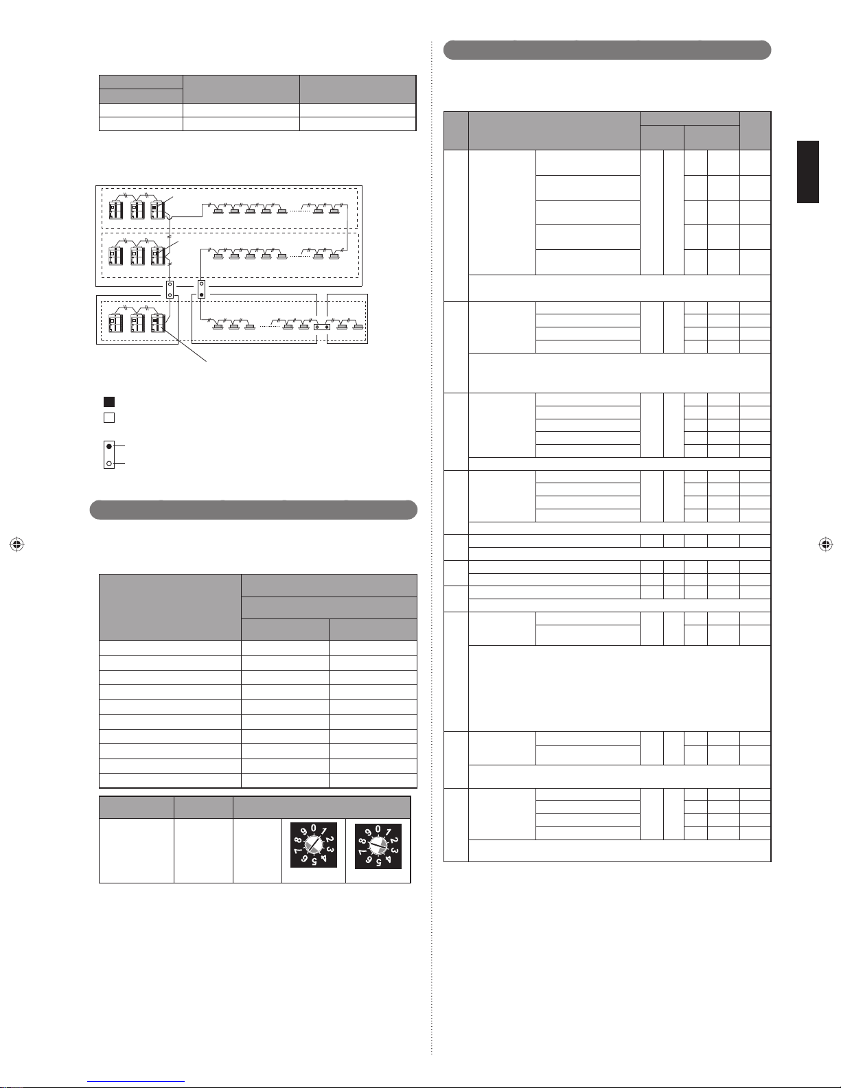
Confi gure the setting (DIP switch SET5) of the terminal resistor of the outdoor units as
shown below from conditions 1 to 3.
SET5
4
OFF Disable (Factory setting)
ON Enable -
Figure: Terminal resistor setting
Master unit
Master unit
Master unit
NS2 (Network segment 2)
About the setting of terminal resistor
Outdoor unit (Master unit)
:on
:off
Signal amplifi er
Install
Do not install
Terminal resistor Remarks
NS1 (Network segment 1)
(Set terminal resistor at outdoor units)
Terminal resistor: on
Refrigerant system1
Terminal resistor: off
Refrigerant system2
Refrigerant system3
NS3 (Network segment 3)
Terminal resister: on
NS4 (Network
segment 4)
Rotary switch setting7. 3.
The rotary switch (REF AD) sets the refrigerant circuit address of the outdoor unit.
Confi gure the settings only on the master unit of a refrigerant system.
If multiple refrigerant systems are connected, set the rotary switch (REF AD) as
shown in the table below.
Rotary Switch Setting
Refrigerant circuit address
000
101
202
303
404
・・・
・・・
97 9 7
98 9 8
99 9 9
Setting Setting range Type of switch
Refrigerant circuit
address
0–99
Setting
example
63
REF AD
×10 ×1
REF AD × 10 REF AD × 1
Push button setting7. 4.
Various functions can be set when necessary.
Perform settings after all indoor units have stopped operation.
A: List of SettingsTable.
No Setting Item
Standard (40 to 65 m)
Short (less than 40 m) 0 1
Pipe length setting *1
00
Pipe length means the length between master outdoor unit and the nearest
indoor unit.
Sequential start
shift *1
10
The start-up timing of outdoor unit (compressor) can be set up so that it can
delay several seconds.
This feature is useful when multiple number of outdoor units are installed and
turned on at the same time to limit the starting current.
Cooling capacity
shift *1
11
Set this item when necessary.
Heating capacity
shift *1
12
Set this item when necessary.
(Forbidden) 1 3 0 0
13
(Forbidden) 1 4 0 0
14
(Forbidden) 1 5 0 0
15
Switching between
batch stop or
emergency stop
This mode selects the pattern of the stop function to be operated by the external
input terminal (CN134).
• Batch stop: The stop of all indoor units connected to same refrigerant system
20
due to input signal coming from CN134.
• Emergency stop: When emergency stop is actuated, the indoor unit does not
accept the operation command from the remote controller. On the other hand,
when the emergency stop is released (no input from CN134), the air conditioner does not return to the original operation until the indoor unit is turned on
by the remote controller.
Snow falling
protection fan
mode *1
22
This mode operates the fans of outdoor units in order to prevent the units from stopping operation when they are covered by snow.
Interval setting
for snow falling
protection fan
23
mode *1
When the snow falling protection fan mode is set, the operation interval of the fans
of outdoor units can be selected.
Medium (65 to 90 m) 0 2
Long 1 (90 to 120 m) 0 3
Long 2 (120 to 150 m) 0 4
Normal
21 sec. Delay 0 1
42 sec. Delay 0 2
63 sec. Delay 0 3
Normal mode
Save energy mode 0 1
High power mode 1 0 2
High power mode 2 0 3
(Forbidden) 0 4
Normal mode
Save energy mode 0 1
High power mode 1 0 2
High power mode 2 0 3
Batch stop
Emergency stop 0 1
*1
Val id
Invalid 0 1
Standard (30 minutes)
Short 1 (5 minutes) 0 1
Short 2 (10 minutes) 0 2
Short 3 (20 minutes) 0 3
7 segment LED indicator
First 2
Last 2 digits
digits
00
00
00
10
00
11
00
12
20
22
23
00
00
00
Factory
setting
z
z
z
z
z
z
z
z
z
z
Rotary Switch (REF AD×1): Factory setting "0"
Rotary Switch (REF AD×10): Factory setting "0"
En-18
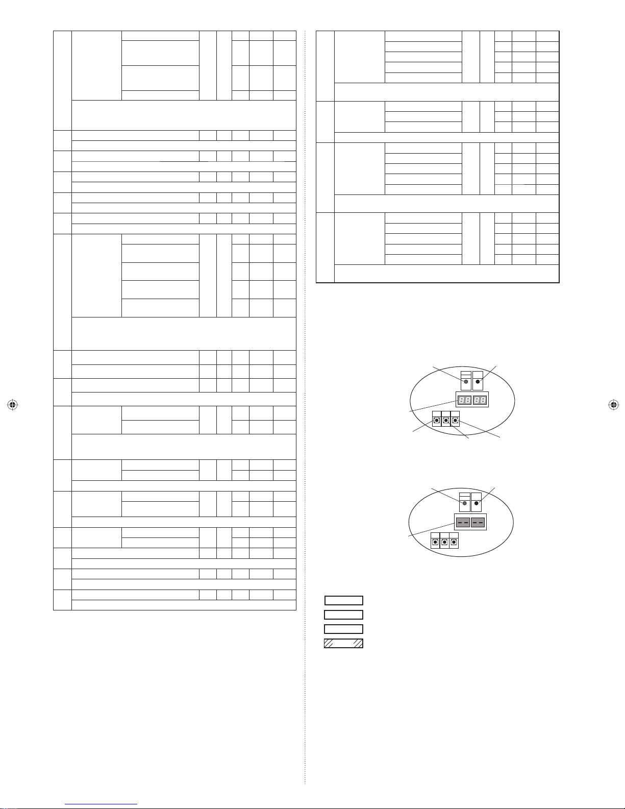
High static pressure
mode
24
Standard
High static pressure 1
(equivalent to 0.12in.WG
(30Pa))
High static pressure 2
(equivalent to 0.32in.WG
(80Pa))
24
00
01
02
(Forbidden) 0 3
When installing a duct to the blow-off outlet of an outdoor unit, set the high static
pressure mode according to the static pressure of the duct to be installed.
Furthermore, use this setting if the air blow of an outdoor unit is poor, such as when
installed in a place with a low ceiling.
(Forbidden) 2 5 0 0
25
(Forbidden) 2 6 0 0
26
(Forbidden) 2 7 0 0
27
(Forbidden) 2 8 0 0
28
(Forbidden) 2 9 0 0
29
Level 1 (stop)
Level 2 (operated at 40%
capacity)
Energy saving
level setting *1
30
The capacity limit can be selected by the external input terminal (CN133) when
operating with the “Energy Saving Peak Cut function”.
The lower the level, the more the effect of energy saving, but the cooling/heating
performance will also drop.
(Forbidden) 3 2 0 0
32
(Forbidden) 3 3 0 0
33
Level 3 (operated at 60%
capacity)
Level 4 (operated at 80%
capacity)
Level 5 (operated at 100%
capacity)
30
00
01
02
03
04
z
Electricity meter
No. setting 1 *2
70
Setting number (x00)
00
Setting number (x01) 0 1
······ ··· ···
70
Setting number (x98) 9 8
z
Setting number (x99) 9 9
Set the ones digit and tens digit of the No. of the electricity meter connected to
CN135.
Electricity meter
No. setting 2 *2
71
z
Set the hundreds digit of the No. of the electricity meter connected to CN135.
Setting number (0xx)
Setting number (1xx) 0 1
71
Setting number (2xx) 0 2
Setting number (xx00)
z
Electricity meter
z
pulse setting 1 *3
72
Setting number (xx01) 0 1
······ ··· ···
72
Setting number (xx98) 9 8
00
00
z
z
Setting number (xx99) 9 9
z
z
z
Set the ones digit and tens digit of the No. of the electricity meter pulse setting
connected to CN135.
Electricity meter
pulse setting 2 *3
73
Setting number (00xx)
Setting number (01xx) 0 1
······ ··· ···
73
Setting number (98xx) 9 8
00
z
Setting number (99xx) 9 9
Set the hundreds digit and thousands digit of the electricity meter pulse setting
connected to CN135.
*1: Do not set this for outdoor units with Slave setting.
*2: When electricity meter No. is set to “000” and “201 to 299”, the pulses input to
CN135 become ineffective. Available setting number is "001" to "200"
*3: When the electricity meter pulse setting is set to “0000”, the pulses input to
CN135 become ineffective. Available setting number is "0001" to "9999"
(1) Turn on the power of the outdoor unit and enter standby mode.
When system is normal•
z
z
POWER/MODE lamp lights up. (ERROR lamp is off.)
POWER/MODE lamp:
ON
ERROR lamp: OFF
POWER
ERROR
MODE
LED101
LED102
(GREEN)
(RED)
LED105 LED104
Capacity priority
setting (in low
noise mode) *1
40
If the cooling/heating performance becomes insuffi cient when the low noise mode is set,
it is possible to set “capacity priority” that automatically cancels the low noise mode (once
performance is restored, the mode will automatically return to the low noise mode).
Low noise mode
setting *1
41
Low noise mode
operation level
42
setting
*1
Off (quiet priority)
On (capacity priority) 0 1
Off (Normal)
On (Low noise mode) 0 1
Level 1 (55 dB)
Level 2 (50 dB) 0 1
40
41
42
00
00
00
The noise level when operating in the low noise mode can be set.
Back up operation 1
60
*1
(Forbidden) 6 1 0 0
61
(Forbidden) 6 2 0 0
62
(Forbidden) 6 3 0 0
63
On
Off 0 1
60
00
z
7 segment LED indicator:
OFF
MODE/EXIT button
When system is abnormal•
z
z
z
Check the settings as there is an error in the settings for outdoor unit address (DIP switch
SET3-1, 2) or number of connected slave units (DIP switch SET3-3, 4).
POWER/MODE lamp:
ON
7 segment LED indicator:
"-" display
z
z
z
(2) Setting method
Use the “MODE/EXIT”, “SELECT”, and “ENTER” buttons to confi gure settings accord-
ing to the procedures below.
(If no setting is made, the factory default setting will be displayed.)
MODE/EXIT
SELECT
ENTER
ENTER
: Press the “MODE/EXIT” button.
: Press the “SELECT” button.
: Press the “ENTER” button.
: Press the “ENTER” button for more than 3 seconds.
MODE
SELECT ENTER
/EXIT
SW108 SW109
SW107
SELECT button
MODE
SELECT ENTER
/EXIT
SW107 SW108 SW109
POWER
ERROR
MODE
LED101
LED102
(GREEN)
(RED)
LED105 LED104
ENTER button
ERROR lamp:
Blinking
En-19
1: FUNCTION Setting
First 2 digits
Last 2 digits
MODE/EXIT
7 segment LED indicator
(LED105, LED104)
(Flashing)
Signalamplifieraddresssetting7.5.
Signalamplifieraddresssetting7.5.1.
When using signal amplifi ers, the address for signal amplifi ers must be set.
The address for signal amplifi ers can be set automatically from 1 outdoor unit (master
unit) on the network.
Refer to the next section “Fig. Wiring example for automatic address setting” for the
wiring example.
(For manual setting of address, refer to the signal amplifi er installation manual.)
SELECT
ENTER
2: Setting the
fi rst 2 digits
SELECT
Every press of the
“SELECT” button will
change the setting
number for the fi rst 2
digits.
(When [F3] to [F9] are displayed, continue to press
the “SELECT” button until [F2] is displayed.)
3: Setting the last 2 digits
Continue to press the “SELECT” button
until the desired number appears at the
ENTER
MODE/EXIT
last 2 digits.
SELECT
SELECT
SELECT
SELECT
SELECT
Procedures to enable automatic address setting 7. 5. 2.
on signal amplifi er
When setting the address of the signal amplifi er, please use the factory setting. (See
the installation manual of the signal amplifi er)
When the system is normal, nothing will be displayed on the 7 segment indicator.
When ERROR is displayed, inspect the units.
Use the “MODE/EXIT”, “SELECT”, and “ENTER”, and ENTER buttons on the outdoor
unit PC board to confi gure settings according to the procedures below.
1: FUNCTION Setting
First 2 digits
Last 2 digits
MODE/EXIT
SELECT
SELECT
ENTER
Automatic address setting
for signal amplifiers
SELECT
(The indicator when the
main power is turned on)
(When [F4] to [F9] are displayed,
continue to press the “SELECT”
button until [F3] is displayed.)
Press the “SELECT” button until
“10” is displayed.
SELECT
MODE/EXIT
ENTER
Setting is complete when the lamp lights up
Press “ENTER” button to return to “2. Setting
the first 2 digits” (If there is no operation for
5 seconds after the setting, the indicator will
return to “2: Setting the first 2 digits”.)
ENTER
MODE/EXIT
SELECT
(Continue to press the
“SELECT” button until the
desired number appears at
the last 2 digits.)
ENTER
SELECT
Setting is complete when the lamp lights up
Press “ENTER” button to return to “2. Setting the
fi rst 2 digits” (If there is no operation for 5 seconds
after the setting, the indicator will return to
“2: Setting the fi rst 2 digits”.)
ENTER
ENTER
MODE/EXIT
End
Press the “ENTER” button for
more than 3 seconds.
Setting is complete when the
number of units is displayed
Indoor unit address setting7. 6.
Indoor unit address setting7. 6. 1.
Address must be set for the indoor unit.
Manual setting → • When setting with the switch inside the indoor unit, refer to
• When setting with a remote controller, refer to the remote
Automatic setting → • Check that the wiring is as shown in the fi gure below.
the indoor unit installation manual.
controller installation manual.
Operate using the master outdoor unit of each refrigerant
system.
EXIT: Press the “MODE/EXIT” button to cancel the setting mode.
En-20

Wiring example for automatic address settingFig.
(1) Signal amplifi er wiring example
(2)(3) Indoor unit wiring example
(Connect the indoor and outdoor units of the same refrigerant system as shown
below.)
Refrigerant system1
Master unit
Refrigerant system2
Master unit
NOTE)
The automatic address function can be used for a maximum of 64 indoor units •
installed to the same refrigerant system. When network is connected to other
refrigerant systems, the automatic address function cannot be used.
The addresses of indoor units that have been confi gured automatically cannot be •
assigned in the order when they are installed. (Refer to the indoor unit installation
manual for the procedures to check the addresses.)
Procedures to enable automatic address setting 7. 6. 2.
on indoor units
Check that the rotary switch IU AD on the indoor unit PC board is set to “00”.If it is not
set to “00”, it means the address of that device is not set. (Factory default is “00”).
Turn on the power of the indoor and outdoor units.
When the system is normal, nothing will be displayed on the 7 segment LED indicator.
When ERROR is displayed, inspect the units.
Use the “MODE/EXIT”, “SELECT”, and “ENTER” buttons on the outdoor unit PC
board to confi gure settings according to the procedures below.
First 2 digits
2128214
314256 8171128
1: FUNCTION Setting
Last 2 digits
MODE/EXIT
SELECT
(The indicator when the
main power is turned on)
(1) Signal amplifi er
126
(2)
3
(3)
RB unit address setting7. 7.
CAUTION
After the address confi guration is complete for the indoor and outdoor units as well
as for the signal amplifi er, confi gure the RB unit address settings.
RB unit address setting7. 7. 1.
Address must be set for the RB unit.
Check the wiring. (Refer to 6.5 Transmission Line)
Manual setting → • When setting with the switch inside the RB unit, refer to the
Automatic setting → • Operate using the master outdoor unit of each refrigerant
Procedures to enable automatic address setting 7. 7. 2.
on RB units
Check that the rotary switch REF AD and RB AD on the RB unit PC board is set to “00”.
If it is not set to “00”, it means the address of that device is not set. (Factory default is
“00”).
Turn on the power of the RB units, indoor and outdoor units.
When the system is normal, nothing will be displayed on the 7 segment LED indicator.
When ERROR is displayed, inspect the units.
Use the “MODE/EXIT”, “SELECT”, and “ENTER” buttons on the outdoor unit PC
board to confi gure settings according to the procedures below.
First 2 digits
RB unit installation manual.
system.
1: FUNCTION Setting
Last 2 digits
(The indicator when the
main power is turned on)
MODE/EXIT
SELECT
SELECT
(When [F4] to [F9] are displayed,
continue to press the “SELECT”
button until [F3] is displayed.)
End
SELECT
ENTER
Automatic address setting
for indoor units
SELECT
ENTER
ENTER
(When [F4] to [F9] are displayed,
continue to press the “SELECT”
button until [F3] is displayed.)
Press the SELECT button until
“11” is displayed.
Press the “ENTER” button
for more than 3 seconds.
The number of indoor units with normal settings will be displayed at the fi rst 2 digits of
the 7 segment LED indicator. The number
of indoor units with error will be displayed
at the last 2 digits.
NOTE) After the “ENTER” button is
pressed, the end processing will occur for
about 30 seconds. During this period, the
7 segment will blink.
End
ENTER
Automatic address setting
for RB units
SELECT
ENTER
ENTER
Press the SELECT button
until “22” is displayed.
Press the “ENTER” button
for more than 3 seconds.
The number of RB units for which
automatic address setting was
successful will be shown in the
fi rst two digits. The number of RB
units for which it was unsuccessful
will be shown in the last two digits.
Note: Incorrect confi guration of
the rotary switch "RB_AD" or
"REF AD" on the RB unit PC
board or incorrect wiring may
lead to automatic address setting
failure.
En-21
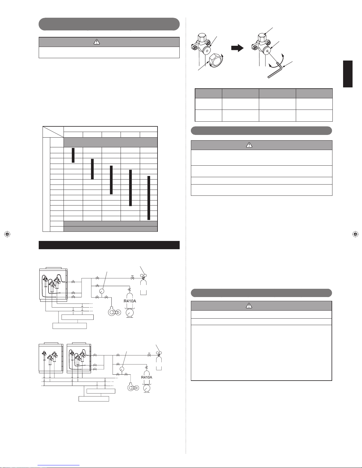
7. 8.
Resistance measurement of transmission cable
(Measure with breaker OFF)
CAUTION
Do not turn on the power if the resistance between the terminals of the transmission cable is abnormal. Otherwise, the circuit board may be damaged.
Measure the resistance between 2 terminals of a transmission cable.
Transmission cable connecting indoor units, outdoor units, and signal (1)
amplifi ers
Measure the resistance of the signal amplifi er terminal and the terminal of the
indoor and outdoor units connected farthest away from the device where terminal
resistor is measured.
A value from the table is displayed, depending on the distance from the signal
amplifi er and the device where the terminal resistor is set.
This value is an estimate.
Transmission cable connecting outdoor units in a refrigerant system(2)
The resistance between the terminals of the transmission cable is 45-60Ω.
This value is an estimate.
Fig. B
Val ve
Open
Close
Cap
ATable.
Valv e t ype Spi ndle Cap Ch argin g cap
Liquid
Suction gas
Discharge gas
9.0 to 12.0 N·m
(90 to 120 kgf·cm)
27.0 to 33.0 N·m
(270 to 330 kgf·cm)
Charging cap
Spindle
Open
Close
20.0 to 24.0 N·m
(200 to 240 kgf·cm)
25.0 to 30.0 N·m
(250 to 300 kgf·cm)
Hexagon
wrench
12.5 to 16.0 N·m
(125 to 160 kgf·cm)
12.5 to 16.0 N·m
(125 to 160 kgf·cm)
Distance from termination resistor (m)
0 ~100 ~ 200 ~ 300 ~400 ~500
A short circuit somewhere or 2 or more termination
0 ~ 50
resistors are connected
50
60
70
80
90
100
110
120
130
140
150
160
170
180
190 ~ Faulty contact or wiring length over 500 m
Approximate resistance (Ω)
1K ~∞ Faulty contact, open circuit, or no termination resistor
PIPE INSTALLATION II8.
A Connection systemFig.
In case of connected 1 outdoor unit A)
Outdoor unit
Pressure gauge
Pressure regulating
valve
Nitrogen
Sealing test8. 1.
CAUTION
Use only nitrogen gas.•
Never use refrigerant gas, oxygen, in fl ammable gas or poisonous gas to pressur-
ize the system. (If oxygen is used. There is danger of an explosion.)
Do not shock during sealing test.•
It can rupture the pipes and cause serious injury.
Do not turn on the power unless all operations are complete.•
Do not block the walls and the ceiling until the sealing test and charging of the •
refrigerant gas have been completed.
After connecting the pipes, perform a sealing test.
Recheck that the spindle of the 3-way valve are closed before performing a sealing
test. (Fig. B)
Pour nitrogen gas through both the liquid pipe and the gas pipe.
Pressurize nitrogen gas to 4.2 MPa to perform the sealing test.
Check all fl are connection areas and brazed areas.
Then, check that the pressure has not decreased.
Compare the pressures after pressurizing and letting it stand for 24 hours, and check
that the pressure did not decreased.
When the outdoor temperature changes 5 °C, the test pressure changes 0.05 *
MPa.
If the pressure has dropped, the pipe joints may be leaking.
If a leakage is found, immediately repair it and perform a sealing test again.
* Decrease the pressure of nitrogen gas before brazing
After completing the sealing test, release the nitrogen gas from both valves.
Release the nitrogen gas slowly.
Vacuum process8. 2.
RB unit
Indoor unit
In case of connected many outdoor units B)
Outdoor unit Outdoor unit
Vac uum
pump
Pressure regulating valve
Pressure gauge
RB unit
Indoor unit
Scale
Vac uum
pump
Scale
Nitrogen
CAUTION
Do not turn on the power unless all operations are complete.
If the system is not evacuated properly, its performance will drop.
If moisture enter the piping, follow below. (i.e., if doing work during the rainy •
season, if the actual work takes long enough that condensation may form on the
inside of the pipes, if rain might enter the pipes during work, etc.)
After operating the vacuum pump for 2 hours, pressurize to 0.05 MPa (i.e., •
vacuum breakdown) with nitrogen gas, then depressurize down to -100.7kPa
(-755mmHg) for an hour using the vacuum pump (vacuum process).
If the pressure does not reach -100.7kPa (-755mmHg) even after depressurizing •
for at least 2 hours, repeat the vacuum breakdown - vacuum process.
After vacuum process, maintain the vacuum for an hour and make sure the pressure does not rise by monitoring with a vacuum gauge.
Evacuation procedure
Remove the caps of the gas pipe and liquid pipe and check that the valves are 1)
closed.
Remove the charging cap. 2)
Connect a vacuum pump and a pressure gauge to a charging hose and connect 3)
it to the charging port.
Activate the vacuum pump and vacuum the indoor unit and connection piping 4)
until the pressure gauge becomes -100.7kPa (-755mmHg).
Evacuate from both the gas pipe and the liquid pipe.
Continue evacuating the system for 1 hour after the pressure gauge reads 5)
-100.7kPa (-755mmHg).
Remove the charging hose and reinstall the charging cap. 6)
En-22

Additional charging8. 3.
CAUTION
Do not turn on the power unless all operations are complete.
After evacuating the system, add refrigerant.
Do not charge the system with a refrigerant other than R410A.
Always keep to the limit on the total amount of refrigerant. Exceeding the limit on
the total amount of refrigerant will lead to malfunction during charging of refrigerant.
Do not reuse recovered refrigerant.
Use an electronic scale to measure the charging amount of refrigerant.
Adding more refrigerant than the specifi ed amount will cause a malfunction.
Charge refrigerant using the liquid pipe.
Adding refrigerant through the gas pipe will cause a malfunction.
Add refrigerant by charging the system with the refrigerant in the liquid state. If
the refrigerant cylinder is equipped with a siphon, it is not necessary to place the
cylinder upright.
Procedure for charging the system with refrigerant8. 3. 1.
Remove the charging cap from the liquid pipe. Use standard refrigeration prac- 1)
tices when charging refrigerant.
Attach a charging hose to the refrigerant cylinder, and connect it to the charging 2)
port.
Add refrigerant by calculating the additional refrigerant volume in accordance with 3)
the calculation formula indicated below.
Remove the charging cap and install the charging hose. 4)
Remove the body caps (suction gas pipe, discharge gas pipe and liquid pipe), 5)
and open the valves.
Close the body caps. 6)
After adding refrigerant, indicate the added charging volume on the unit. 7)
Tighten the body caps and charging caps to the torque values specifi ed in the *
Tabl e A .
To open and close the valves, Use an M4 hexagon wrench for liquid pipe.
Use an M8 hexagon wrench for suction gas pipe and discharge gas pipe.
If you can not charge the specifi ed amount of refrigerant with the above
**
method, be sure to charge the refrigerant through the gas pipe while operating in cooling mode. In order to prevent liquid back-fl ow, carefully operate
the refrigerant cylinder valve so that the refrigerant will fl ow in certain part at
a time.
Checking total amount of refrigerant and calculat-8. 3. 2.
ing the amount of refrigerant charge to be added
The amount of refrigerant charge to be added is the total value of the basic refrig-•
erant charge amount and the value calculated from the length of the liquid pipe.
Round up the value to 2 dec• imal places.
Model HPdFactory charged amount
A72GALH
AJ
A90GALH
AJ
108GALH
AJ
Diameter of liquid pipe (mm)
Calculation of additional amount for outdoor unit(1)
Outdoor unit1 additional
A =
amount for outdoor unit
Outdoor unit3 additional
amount for outdoor unit
Calculation of additional amount for pipe length(2)
Total length
of ø19.05 mm
liquid pipe
B =
8HP 11.8 3.0
10HP 11.8 3.0
12HP 11.8 3.0
Ø6.35 0.021
Ø9.53 0.058
Ø12.70 0.114
Ø15.88 0.178
Ø19.05 0.268
a
a
b × 0.268
m
Outdoor unit2 additional
+
amount for outdoor unit
kg
Total
=
kg
+
(kg/m)
kg
Total length of
ø15.88 mm liquid
(kg)
Additional amount for pipe length (kg/m)
a
+
kg
kg
m
b × 0.178
(kg/m)
pipe
a
Additional amount for
outdoor unit (kg)
b
+
kg
Total length of
ø12.70 mm liquid
Total length of
ø6.35 mm
liquid pipe
Calculation of additional charge refrigerant(3)
C=A+B =
pipe
b × 0.114
m
× 0.021 (kg/
m
(kg/m)
b
m)
Total length
of ø9.53 mm
liquid pipe
+
kg
m
b × 0.058
(kg/m)
Tot al
=
kg
(Round up C to 2 decimal place)
kg
+
kg
kg
Calculation of factory charged amount(4)
d
D =
E=C+D=
Note : Check the total refrigerant amount under the following conditions
Outdoor unit1
factory charged amount
d
Outdoor unit3
factory charged amount
Total refrigerant amount check(5)
For 1 outdoor unit per refrigerant system
: Total amount of refrigerant ≤ 35kg
For 2 outdoor units per refrigerant system
: Total amount of refrigerant ≤ 70kg
For 3 outdoor units per refrigerant system
: Total amount of refrigerant ≤ 105kg
+
kg
Total
=
kg
kg
Condition Computational formula
d
Outdoor unit2
factory charged amount
kg
+
kg
E ≤ 35kg
E ≤ 70kg
E ≤ 105kg
<Calculation>
When there are 3 outdoor units (AJ• 108GALH, AJ A90GALH, AJ A72GALH)
connected to 1 system
Calculation of additional amount for outdoor unit(1)
A=3.0(kg)+3.0(kg)+3.0(kg)=9.0(kg)
Calculation of additional amount for pipe length(2)
If liquid pipe piping length is the following
ø
19.05 : 50m, ø15.88 : 25m, ø12.70 : 0m, ø9.53 : 20m, ø6.53 : 15m
Additional charge volume B=50(m)×0.268(kg/m)+25(m)×0.178(kg/m)
=19.325kg
Calculation of additional charge refrigerant(3)
C=A+B =9.0(kg)+19.33(kg)=28.33(kg)
Calculation of factory charged amount(4)
D=11.8(kg)+11.8(kg)+11.8(kg)=35.4 (kg)
Check the total amount of refrigerant(5)
When 3 outdoor units are connected to 1 system, the following condition must be
satisfi ed.
Condition: E=C+D ≤ 105(kg)
Calculation: 28.33(kg)+35.4(kg)=63.73(kg)<105(kg)
→ No problem if the above condition is satisfi ed.
+0(m)×0.114(kg/m)+20(m)×0.058(kg/m)
+15(m)×0.021(kg/m)
En-23
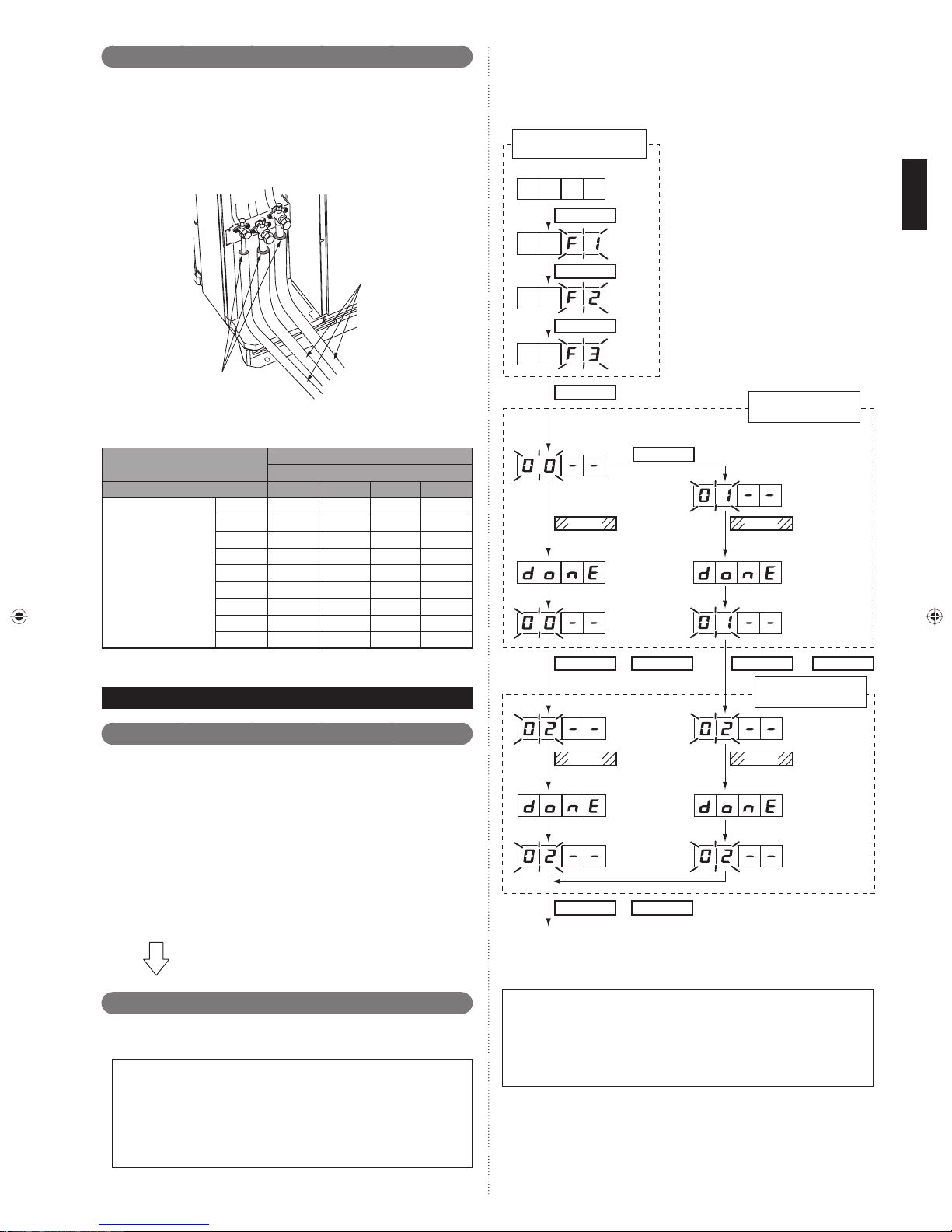
Installing insulation8. 4.
Install insulation material after conducting the “8.1 Sealing Test”.•
To prevent condensation and water droplets, install insulation material on the refriger-•
ant pipe.
Refer to the table to determine the thickness of the insulation material.•
If the outdoor unit is installed at a level that is higher than the indoor unit, the water •
that has condensed in the 3-way valve of the outdoor unit could travel to the indoor
unit.
Therefore, use putty in the space between the pipe and the insulation to prevent the
entry of water.
Perform test operation for each refrigerant system.
You can set “cooling test run" or “heating test run” with the push button on the outdoor
unit PC board.
Test operation setting method
Use the “MODE/EXIT”, “SELECT”, and “ENTER” buttons on the outdoor unit PC board
to confi gure settings according to the procedures below.
FUNCTION settings
First 2 digits
Last 2 digits
MODE/EXIT
Insulation
Putty
Selection of insulationTa ble .
(for using an insulation material with equal heat transmission rate or below
0.040W/(m·k))
Insulation material
Minimum thickness (mm)
Relative humidity ≤ 70% ≤ 75% ≤ 80% ≤ 85%
Pipe diameter (mm)
When an ambient temperature and relative humidity exceed 32 °C, please strength-*
en heat insulation of refrigerant pipe.
6.35 8 10 13 17
9.52 9 11 14 18
12.70 10 12 15 19
15.88 10 12 16 20
19.0510131621
22.22 11 13 17 22
28.58 11 14 18 23
34.92 11 14 18 24
41.27 12 15 19 25
TEST RUN9.
SELECT
SELECT
(When [F4] to [F9] are displayed, continue to
press the SELECT button until [F3] is displayed.)
ENTER
SELECT
ENTER
Press the “ENTER” button
for more than 3 seconds.
This will be
displayed when
the cooling test
operation is
complete.
This will be
displayed after
5 seconds.
ENTER
SELECT SELECT
or
For heating operation, press the
“SELECT” button until “01” is displayed.
ENTER
Press the “ENTER” button
for more than 3 seconds.
Settings for starting
test run operation
This will be
displayed when
the heating test
operation is
complete.
This will be
displayed after
5 seconds.
ENTER
or
Settings for stopping
test run operation
Pre-test run check items9. 1.
Before the test operation, check the following items.
Is there a gas leakage? (At pipe connections {fl ange connections and brazed
①
areas})
Is the system charged with the specifi ed volume of refrigerant?
②
Is the refrigerant circuit address correct?
③
Is a breaker installed at the power supply cable of every outdoor unit?
④
Are the cables connected to the terminals without looseness, and in accordance with
⑤
the specifi cations?
Are the initial settings of the switches of the outdoor unit correctly confi gured?
⑥
Is the 3-way valve of the outdoor unit open? (suction gas pipe, discharge gas
⑦
pipe and liquid pipe)
Is power supplied to the crank case heater for more than 12 hours? Electricity
⑧
current in short period of time may result in compressor damage.
Are all the indoor units within the same coolant system connected to the power?
⑨
Operating indoor units which are not connected to the power may result in malfunctions.
After checking that the above items are all in order, refer to “9.2 Test
operation method” to test operation of the unit.
If there are problems, adjust immediately and recheck.
Test operation method9. 2.
Be sure to confi gure test run settings only when the outdoor unit has stopped
operating.
Depending on the communication status between the indoor and outdoor units, •
it may take several minutes for the system to start operating after settings for the
test run are complete.
After the test run settings are complete, all the outdoor units and the connected •
indoor units will start operating. Room temperature control will not activate during
test operation (continuous operation).
If a knocking sound can be heard in the liquid compression of the compressor, •
stop the unit immediately and then energize the crank case heater for a suffi cient
length of time (more than 12 hours) before restarting the operation.
ENTER ENTER
Press the “ENTER” button
for more than 3 seconds.
This will be displayed when the
cooling operation
mode is canceled.
This will be
displayed after
5 seconds.
ENTER
MODE/EXIT
EXIT
After the test operation is complete, turn off the power. Attach the cover of the electrical
compartment box and the front panel of the outdoor unit.
Note
Check that the indoor and outdoor units connected to the same refrigerant system •
are operating normally.
When indoor or outdoor units are not operating, or when the indoor and outdoor •
units of other refrigerant systems are operating, the indoor/outdoor unit address or
DIP switch for the number of connected slave units are not confi gured correctly.
The system will not operate normally with an incorrect DIP switch setting.•
Stop the system immediately and recheck the DIP switch setting.
or
Press the “ENTER” button
for more than 3 seconds.
This will be dis-
played when the
heating operation
mode is canceled.
This will be
displayed after
5 seconds.
En-24
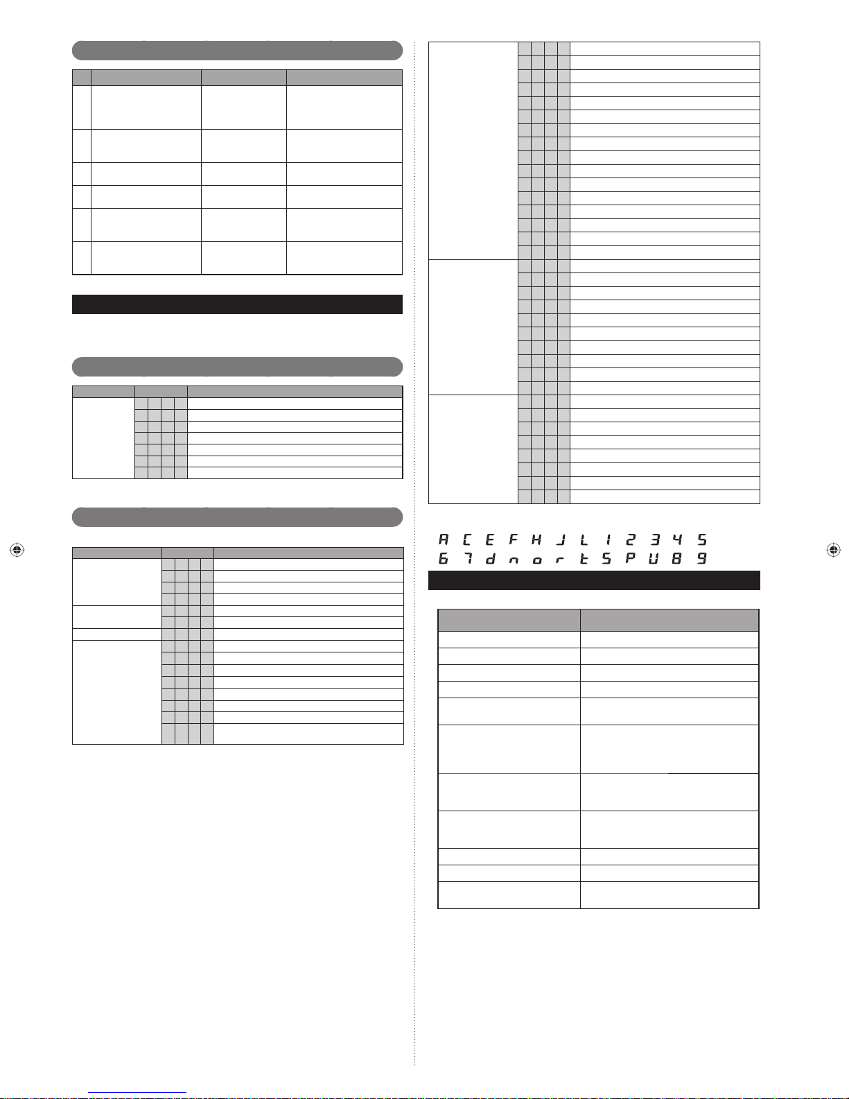
㪃 㪃 㪃 㪃 㪃 㪃 㪃
㪃
㪃
㪑
㪘㪑㪚㪑
㪜㪑㪝㪑
㪃 㪃 㪃
㪃 㪃
㪃
㪃
㪑
㪃
㪃 㪃
㪑
Checklist9. 3.
Check description Check method Criteria
High and low pressure
1
values are normal.
Drain water is dis-
2
charged smoothly
through the drain hose.
Indoor and outdoor unit
3
fans are operating.
Compressor operates after
4
the indoor unit operates.
Difference between inlet
5
and outlet temperatures
is normal.
6 Error is not displayed
Check it with a
pressure gauge.
Check it by pouring water.
Check them visually.
Check the operating sound.
Measure the inlet
and outlet temperatures.
Check the 7
segment LED
indicator
Cooling: low pressure approx. 0.8 MPa
Heating: high pressure approx. 3.0 MPa
―
―
―
Temperature difference 10
degrees
Error blinking or no error
code display
LED Status10.
You can determine the operating status by the lighting up and blinking of the 7 segment LED indicator.
Check the status using the table below.
Normal operation mode10. 1.
Mode Code Description
Operation
Communication error
Function setting error
Indoor unit actuator error E 5 U. 1 Indoor unit error
Outdoor unit PCB/Electrical component/ Switch
error
CL Cooling
Ht Heating
o r During oil recovery operation
d F During defrosting operation
P C During peak cut operation
L n During low noise operation
S n During setting of snowfall mode
Error mode10. 2.
Mode Code Description
E 1 3. 1 Communication error between Outdoor unit
E 1 4. 1 Outdoor unit network communication 1 error
E 1 4. 2 Outdoor unit network communication 2 error
E 1 4. 5 The number of indoor unit shortage
E 2 8. 1 Auto address setting error
E 2 8. 4 Signal amplifi er auto address error
E 6 1. 5 Outdoor unit reverse phase, missing phase wire error
E62.3Outdoor unit EEPROM access error
E 6 2. 6 Inverters communication error
E 6 2. 8 EEPROM data corrupted error
E 6 3. 1 Inverter error
E 6 7. 2 Inverter PCB short interruptions detection
E68.2
E69.1
Rush current limiting resister temp rise protection
Outdoor unit transmission PCB parallel
communication error
E 7 1. 1 Discharge temp. sensor1 error
E 7 2. 1 Compressor temp. sensor1 error
E 7 3. 4 Heat Ex.1 gas temp. sensor error
E 7 3. 5 Heat Ex.1 liquid temp. sensor error
E73.6Heat Ex.2 gas temp. sensor error
E 7 3. 7 Heat Ex.2 liquid temp. sensor error
Outdoor unit sensor
error
Outdoor unit actuator
error
Refrigerant system
abnormal
E 7 4. 1 Outdoor temp. sensor error
E 7 5. 1 Suction gas temp. sensor error
E77.1Heat sink temp. sensor error
E 8 2. 2 Sub-cool Heat Ex. gas outlet temp. sensor error
E83.1Liquid pipe temp. sensor1 error
E 8 3. 2 Liquid pipe temp. sensor2 error
E 8 4. 1 Current sensor 1 error (permanent stop)
E 8 6. 1 Discharge pressure sensor error
E 8 6. 3 Suction pressure sensor error
E 8 6. 4 High pressure switch 1 error
E 9 3. 1 Inverter compressor start up error
E94.1Trip detection
E 9 5. 5 Compressor motor loss of synchronization
E 9 7. 1 Outdoor unit fan motor lock error
E97.5
E 9 7. 9 Fan motor driver abnormal
E 9 A. 1 Coil1 (Expansion valve1) error
E 9 A. 2 Coil2 (Expansion valve2) error
E 9 A. 3 Coil3 (Expansion valve3) error
E9U.2Slave unit error
E A 1. 1 Discharge temperature 1 abnormal
E A 3. 1 Compressor1 temperature abnormal
E A 4. 1 High pressure abnormal
E A 4. 2 High pressure protection1
E A 5. 1 Low pressure abnormal
E A 6. 3 Outdoor heat exchanger 1 gas temperature abnormal
E A 6. 4 Outdoor heat exchanger 2 gas temperature abnormal
E A C. 4 Heat sink temperature abnormal
Fan motor temperature abnormal (protected operation )
7 segment LED indicator:
㪡㪑
㪃
㪍㪑
㪻㪑 㫅㪑 㫆㪑㫉㪑
㪎㪑
㪟
㪣㪑
㪈㪑 㪉㪑
㫋㪑
㪃
㪬㪑
㪧
㪪㪑
㪃
㪃
INFORMATION11.
Main contents of label
Item Detail
Model name 1. Model name
Serial number 2. Serial number
Electric characteristics 3. Phase, rated voltage, and frequency
Weight 4. Product weight
Capacity 5.
Current 6.
Input power 7.
Max. Current 8.
Air circulation 9. Air circulation
Noise level10. Noise level
Refrigerant11.
Cooling/heating capacity under cooling/
heating condition (refer to item 15)
Electric current during cooling/heating
operation under cooling/heating condition
(refer to item 15)
Input during cooling/heating operation
under cooling/heating condition (refer
to item 15)
Maximum electric current (temperature
condition is max. cooling condition [refer
to item 16])
Refrigerant type and initial charging
amount
㪌㪑㪊㪑 㪋
㪐㪑
㪏㪑
En-25
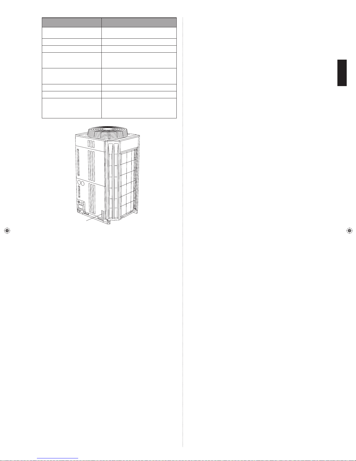
Item Detail
Max. pressure (HP/LP)12.
Protection13. Protection level against dust and water
Working temperature14. Working temperature
Condition of cooling/heating15.
Condition of max. cooling16.
Manufacture year17. Manufacture year
Origin18. Origin country
Manufacturer19.
Means pressure of High Pressure side/
Low Pressure side
Dry-bulb temperature and wet-bulb
temperature under standard cooling/
heating condition
Dry-bulb temperature and wet-bulb
temperature at maximum electric current and input
Manufacturer
FUJITSU GENERAL LIMITED
Address : 1116, Suenaga, Takatsu-ku,
Kawasaki 213-8502, Japan
Label
En-26
INSTALLATIONSANLEITUNG
TEILE NR. 9378945074
VRF-System Außengerät
INHALT
1. SICHERHEITSMASSNAHMEN ...............................................................................1
2. ÜBER DAS GERÄT .................................................................................................2
2. 1. Vorsichtsmaßnahmen beim Gebrauch des R410A Kühlmittels ..................... 2
2. 2. Spezialwerkzeuge für R410A ........................................................................ 2
2. 3. Zubehör ........................................................................................................ 2
2. 4. Kombinationen .............................................................................................. 2
2. 5. Optionale Teile .............................................................................................. 3
3. INSTALLATIONSARBEIT ......................................................................................... 3
3. 1. Einen Installationsort aussuchen ..................................................................3
3. 2. Ablassvorgang .............................................................................................. 3
3. 3. Installationsmaße .......................................................................................... 3
3. 4. Transport des Außengeräts...........................................................................5
3. 5. Installation des Geräts .................................................................................. 6
4. SYSTEMKONFIGURATION..................................................................................... 6
4. 1. Systemkonfi guration .....................................................................................6
4. 2. Leitungsauswahl ........................................................................................... 7
4. 3. Schutz der Leitungen .................................................................................... 8
5. LEITUNGSINSTALLATION ......................................................................................8
5. 1. HARTLÖTUNG ............................................................................................. 8
5. 2. Anschlüsse der Innengerätleitung ................................................................. 8
5. 3. Leitungsmethode .......................................................................................... 9
5. 4. Mehrere Verbindungen ............................................................................... 10
6. ELEKTRISCHE VERDRAHTUNG ......................................................................... 11
6. 1. Die Vorsichtsmaßnahmen bei der elektrischen Verdrahtung ...................... 11
6. 2. Verkabelungsmethode ................................................................................12
6. 3. Ausbrechloch .............................................................................................. 13
6. 4. Selektrisches Netzkabel und Schutzschalterr ............................................. 13
6. 5. Übertragungsleitung .................................................................................... 13
6. 6. Verdrahtungsvorgang .................................................................................. 15
6. 7. Externer Eingang und externer Ausgang .................................................... 16
7. FELDEINSTELLUNG ............................................................................................. 17
7. 1. Schalter Feldeinstellung .............................................................................. 17
7. 2. DIP-Schalter-Einstellung ............................................................................. 17
7. 3. Drehschaltereinstellung ..............................................................................18
7. 4. Drucktasteneinstellung ................................................................................18
7. 5. Adresseinstellung Signalverstärker .............................................................20
7. 6. Adresseinstellung Innengerät......................................................................20
7. 7. Kältemittel-Abzweigungs-Gerät Adresseinstellung ...................................... 21
7. 8. Widerstandsmessung des Übertragungskabels
(Messung mit ausgeschaltetem Schutzschalter) ......................................... 22
8. LEITUNGSINSTALLATION II .................................................................................22
8. 1. Dichtungstest .............................................................................................. 22
8. 2. Vakuumvorgang ..........................................................................................22
8. 3. Zusätzliches Einfüllen ................................................................................. 23
8. 4. Installierung der Isolierung .......................................................................... 24
9. PROBELAUF ......................................................................................................... 24
9. 1. Prüfpunkte vor dem Probelauf ....................................................................24
9. 2. Testbetriebmethode .................................................................................... 24
9. 3. Checkliste ...................................................................................................25
10. LED -Status ........................................................................................................... 25
10. 1. Normaler Betriebsmodus ............................................................................ 25
10. 2. Fehlermodus ............................................................................................... 25
11. INFORMATION ......................................................................................................25
SICHERHEITSMASSNAHMEN1.
Lesen Sie diese Anleitung vor der Installation sorgfältig durch•
Die in diesem Installationshandbuch angegebenen Warnungen und Sicherheitsmaßnahmen •
enthalten wichtige Informationen in Bezug auf Ihre Sicherheit. Beachten Sie diese unbedingt.
Nachdem Sie das Gerät installiert haben, führen Sie einen Probelauf durch, um •
sicher zu stellen, dass das Gerät normal funktioniert. Dann erklären Sie dem Kunden, wie man das Gerät in Betrieb nimmt und wartet.
Übergeben Sie dieses Installationshandbuch bitte zusammen mit der Bedienungs-•
anleitung dem Kunden.
Bitten Sie den Kunden, die Bedienungsanleitung und das Installationshandbuch
so bereitzuhalten, dass zukünftig darauf zurückgegriffen werden kann, wenn das
Hauptgerät bewegt oder repariert wird.
Diese Kennzeichnung weist auf Verfahren hin, die bei
WARNUNG
Verwenden Sie für Installationszwecke ausschließlich Teile, die vom Hersteller
bereitgestellt werden, oder andere vorgeschriebene Teile.
Der Gebrauch nicht spezifi scher Teile verursacht ernste Unfälle, wie zum Beispiel der Herunterfallen des
Geräts, Auslaufen des Kühlmittels, Auslaufen des Wassers, elektrischen Schlag und Feuer.
unsachgemäßer Ausführung zum Tode oder zu schweren
Verletzungen des Benutzers führen könnten.
.
Verwenden Sie zur Installation des Geräts mit dem Kältemittel R410A dafür vorgesehene
Werkzeuge und Rohrmaterialen, die speziell für den Umgang mit R410A gefertigt sind.
Weil der Druck für das Kältemittel R410A ca. 1,6-mal höher liegt als für R22, kann
Verwendung von Rohrmaterial, das nicht für R410A vorgesehen ist, oder eine
unsachgemäße Installation zum Reißen der Rohre oder zu Verletzungen führen.
Es verursacht auch ernsthafte Verletzungen, wie zum Beispiel ein Auslaufen des
Kühlmittels, Auslaufen des Wassers, elektrischen Schock und Feuer.
Führen Sie keine andere Substanz als das vorgeschriebene Kältemittel in den Kältekreislauf ein.
Wenn Luft in den Kältekreislauf gelangt, baut sich ein abnorm hoher Druck auf, der
zum Reißen der Rohrleitungen führt.
Achten Sie darauf das Gerät so wie beschrieben zu installieren, sodass es Erdbeben und Taifune oder andere starke Winde wiederstehen kann.
Eine nicht korrekte Installation kann dazu führen, dass das Gerät umfällt oder herabfällt oder andere Unfälle.
Stellen Sie sicher, dass das Außengerät sicher an einem Ort installiert ist, der das
Gewicht des Geräts tragen kann.
Eine nicht korrekte Installation verursacht Verletzungen durch das Herunterfallen des Geräts.
Wenn ein Kältemittelleck auftritt, muss sichergestellt werden, dass nicht der zulässige Konzentrations-Grenzwert überschritten wird.
Wenn bei einem Kältemittelleck der zulässige Konzentrations-Grenzwert überschritten wird, kann dies zu Unfällen, wie z.B. Sauerstoffmangel, führen.
Wenn es während der Arbeiten zu einem Kältemittelleck kommt, verlassen Sie die
Räumlichkeiten sofort und lüften Sie den Bereich gründlich.
Wenn das Kältemittel Feuer ausgesetzt wird entsteht ein gefährliches Gas.
Elektrische Arbeiten müssen in Übereinstimmung mit diesem Installationshandbuch von einer Person ausgeführt werden, die nach nationalen oder regionalen Bestimmungen hierfür
zugelassen ist. Achten Sie darauf, einen eigenen Stromkreis für das Gerät zu verwenden.
Ein unzureichender Stromversorgungskreis oder unsachgemäß ausgeführte Elektroarbeiten können schwere Unfälle, wie z.B. Stromschlag oder Brand, verursachen.
Verwenden Sie für die Verdrahtung die vorgeschriebenen Kabeltypen, schließen
Sie diese fest an und stellen Sie sicher, dass keine Außenkräfte der Kabel auf die
Klemmenanschlüsse einwirken.
Unsachgemäß angeschlossene oder befestigte Kabel können schwere Unfälle, wie
z.B. Überhitzung der Klemmen, Stromschlag oder Brand, verursachen.
Schalten Sie die Stromversorgung nicht vor dem Abschluss sämtlicher Arbeiten ein.
Das Einschalten der Stromversorgung vor dem Abschluss der Arbeiten kann
schwere Unfälle, wie z. B. Stromschlag oder Brand, verursachen.
Achten Sie nach der Installation darauf, dass es keine Kältemittelleckage gibt.
Wenn das Kältemittel in den Raum leckt und einer Feuerquelle ausgesetzt wird, wie
zum Beispiel einer Lüfterheizung, Ofen oder Brenner, entsteht ein gefährliches Gas.
Verwenden Sie ein Rohr in der Wandöffnung. Ansonsten könnte ein Kurzschluss verursacht werden.
Stellen Sie das Außengerät nicht in Nähe des Balkongeländers auf.
Es könnte passieren, dass Kinder auf das Außengerät klettern und sich über das
Geländer lehnen und herunterfallen.
Verwenden Sie nur ein spezielles Netzkabel. Eine schlechte Verbindung, schlechte Isolierung
und das Überschreiten der zulässigen Stromstärke führt zu elektrischem Schock und Feuer.
Bringen Sie die verbindenden Kabel fest an den Klemmen an. Oder befestigen Sie
sicher mit einem „Kabelentstörer“.
Lose Verbindungen führen zu Fehlfunktionen, elektrischem Schlag oder Brand.
Installieren Sie einen Stromschutzschalter, um den gesamten Wechselstrom gleichzeitig abzuschalten.
Wenn Sie keinen Stromschutzschalter installieren, kann es zu einem elektrischen
Schlag oder Brand kommen.
Achten Sie darauf das Kältemittelrohr zu installieren, bevor Sie den Kompressor in
Betrieb nehmen. Wenn das Kältemittelrohr nicht installiert ist und Sie den Kompressor in betrieb nehmen, während das Ventil geöffnet ist, wird Luft in das System
gesaugt und es entsteht ein anormaler Druck im Kältemittelkreislauf. Dies schädigt
das Gerät und verursacht Verletzungen.
Achten Sie während des Pump-Down-Betriebs darauf, dass der Kompressor
ausgeschaltet wurde, bevor Sie die Kältemittelleitung entfernen. Entfernen Sie nicht
das Verbindungsrohr, während der Kompressor in Betrieb ist, während das 2-Wege
oder 3-Wege-Ventil geöffnet ist. Dies verursacht einen anormalen Druck im Kältemittelkreislauf, der zu Bruchstellen und sogar zu Verletzungen führt.
Wenn es sein kann, dass der Lüfter während der Wartung berührt wird, achten Sie
darauf, den Strom AUS zu stellen, bevor Sie die Wartung durchführen. Selbst wenn
der Betrieb unterbrochen wird kann es sein, dass sich der Lüfter des Außengeräts
dreht, also kann es sein, dass es zu Verletzungen kommt, wenn der Lüfter sich
plötzlich dreht, wenn Sie ihn berühren.
Diese Kennzeichnung weist auf Verfahren hin, die bei un-
VORSICHT
Die Installation dieses Geräts darf nur durch qualifi ziertes Personal erfolgen, das
für den Umgang mit Kältemitteln befugt ist. Beachten Sie die geltenden Bestim-
mungen und Gesetze zum Installationsort.
Bei der Installation sind die vor Ort geltenden Bestimmungen sowie die Installati-
onsanweisungen des Herstellers zu beachten.
Dieses Gerät ist Bestandteil einer Klimaanlage. Es darf nicht einzeln oder zusammen mit Geräten, die nicht vom Hersteller dafür vorgesehen sind, installiert werden.
Die Teile dieses Gerätes sind nicht für die Wartung durch den Benutzer vorgesehen. Wenden Sie sich für Reparaturen immer an autorisiertes Fachpersonal.
Wenn Sie das Gerät an einem anderen Ort aufstellen möchten, wenden Sie sich bitte für
die Trennung der Anschlüsse und die erneute Installation an autorisiertes Fachpersonal.
Lassen Sie sich die Zustimmung des Vertriebsnetzwerkbetreibers bezüglich der Leistungs-•
kapazität des Stromversorgungssystems, der Spezifi kation der Kabel und der Oberschwin-
gungsströme usw. geben, wenn Sie das Außengerät an die Stromversorgung anschließen.
Dieses Gerät muss an eine Stromversorgung mit einer Impedanz von 0,33 Ohm •
oder weniger angeschlossen werden. Wenn die Stromversorgung diese Voraussetzung nicht erfüllt, setzen Sie sich bitte mit dem Stromanbieter in Verbindung.
Dieses Produkt ist für den professionellen Gebrauch gedacht.•
Achten Sie darauf, einen entsprechenden Stromkreislauf zu verwenden.
Verwenden Sie niemals eine Stromversorgung, die mit einem anderen Gerät geteilt wird.
sachgemäßer Ausführung möglicherweise zu Sach- oder
Personenschäden führen können.
De-1
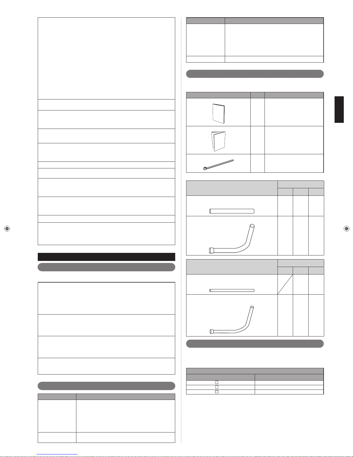
Installieren Sie das Gerät nicht in folgenden Bereichen:
Bereiche mit hohem Salzgehalt, wie z. B. an der See. •
Dies greift Metallteile an, so dass Teile herabfallen können oder leckendes
Wasser aus dem Gerät austreten kann.
Bereiche, die mit Mineralöl gefüllt sind oder in denen große Mengen ver-•
spritztes Öl oder Dampf auftreten, wie z. B. in einer Küche.
Dies greift Kunststoffteile an, so dass Teile herabfallen können oder leckendes Wasser aus dem Gerät austreten kann.
Bereiche, in denen Substanzen erzeugt werden, die das Gerät beeinträchti-•
gen, wie z. B. Schwefelgase, Chlorgas, Säuren oder Basen.
Dies führt zur Korrosion der Kupferrohre und Hartlötverbindungen und kann
zu einer Kältemittelleckage führen.
Bereich der eine Ausrüstung enthält, der elektromagnetische Interferenzen generiert. •
Dies führt dazu, dass beim Steuerungssystem eine Fehlfunktion verursacht
wird und bewirkt, dass das Gerät normal funktioniert.
Bereiche, in denen brennbare Gase austreten können, die schwebende Kohlefasern oder ent-•
zündlichen Staub enthalten oder fl üchtige brennbare Stoffe, wie Lackverdünner oder Benzin.
Wenn Gas austritt und sich am Gerät ansammelt, kann es einen Brand verursachen.
Vermeiden Sie eine Installation des Geräts an einem Ort, wo es in Kontakt •
mit Tierurin oder Ammoniak kommt.
Die Geräte sind nicht explosionssicher und sollten daher nicht in einer explosionsfähigen Atmosphäre installiert werden.
Verwenden Sie das Gerät nicht für spezielle Zwecke, wie zum Beispiel zur Lagerung von Lebensmitteln, Aufzucht von Tieren, Pfl anzenzucht oder zur Aufbewah-
rung von Präzisionsgeräten oder Kunstwerken. Dadurch kann die Qualität der
aufbewahrten oder gelagerten Objekte herabgesetzt werden.
Erden Sie das Gerät. Verbinden Sie das Massekabel nicht mit einem Gasrohr, Wasserrohr, Blitzableiter oder einem Telefonmassekabel. Eine nicht korrekte Erdung
kann zum elektrischen Schlag führen.
Führen Sie eine Drainage für das Gerät durch, wie im Installationshandbuch beschrieben. Überprüfen Sie, ob das Wasser richtig abgelaufen ist.
Wenn der Ablassvorgang nicht richtig installiert ist, kann Wasser vom gerät heruntertropfen und die Möbel nass machen.
Fassen Sie die Lamellen nicht mit bloßen Händen an.
Achten Sie darauf, dass der Betrieb der Klimaanlage nicht mit dem Schutzschalter ein oder
ausgeschaltet wird. Ansonsten kann es zu Fehlfunktionen oder Wasserleckage kommen.
Wenn Sie das Gerät in der Nähe von Geräten aufstellen, die elektromagnetische
Wellen verursachen und die Geräte generieren höhere harmonische Wellen, stellen
Sie sicher, dass Sie Maßnahmen gegen das Geräusch treffen. Ansonsten kann es
zu Fehlfunktionen oder Störungen kommen.
Wenn die Kurbelwellengehäuseheizung bestromt wird, stellen Sie den Strom bitte
12 Stunden oder mehr ab, bevor der Betrieb beginnt. Wenn die Bestromung kurz
ist, kann es zu Störungen kommen. Abgesehen davon, stellen Sie den Strom nicht
während der Hauptsaison ab.
Kinder müssen beaufsichtigt werden, um sicher zu stellen, dass sie nicht mit dem Gerät spielen.
Dieses Produkt darf nicht von Personen (zum Beispiel Kinder) mit physischen,
sensorischen oder mentalen Behinderungen verwendet werden oder von Personen,
denen die nötige Erfahrung oder die Kenntnis fehlt, es sei denn, sie werden von einer Person, die für ihre Sicherheit verantwortlich ist, überwacht oder sie bekommen
eine Anleitung, wie sie das Gerät zu verwenden haben.
Werkzeugname Geänderter Inhalt für das R22-Werkzeug
Durch Installation eines Vakuumpumpenadapters kann eine
herkömmliche Vakuumpumpe (R22) verwendet werden.
Vak uum pum pe
Gasleckdetektor Spezieller Gasleckdetektor für HFC-Kältemittel R410A.
Durch Installation eines Vakuumpumpenadapters kann •
eine herkömmliche Vakuumpumpe verwendet werden.
Stellen Sie sicher, dass das Pumpenöl nicht in das System •
zurückfl ießt. Verwenden Sie einen, der eine Vakuumein-
saugung von -100,7kPa (5 Tonnen, -755mmHg) aushält.
Zubehör2. 3.
Verwenden Sie Verbi ndungsteile, w enn nöti g.
Werfen Sie nicht die Verbindungsteile weg, solange die Installation noch nicht abgeschlossen ist.
Name und Form Menge Anwendung
Pfl ichtenheft
Installationsanleitung
Kabelklemme
Verbindungsrohr für Sauggasleitung
Verbindungsrohr A
(Großer, gerader Typ)
Verbindungsrohr B
(Großer, L-Typ)
—
1
(Dieses Buch)
1
Zum Verbinden des Stromkabels
und des Übertragungskabels
4
Modellcode
72 90 108
111
111
ÜBER DAS GERÄT2.
Vorsichtsmaßnahmen beim Gebrauch des R410A Kühlmittels2. 1.
Passen Sie bei den folgenden Punkten besonders gut auf:
Da der Arbeitsdruck 1,6 mal höher ist als der des R22-Modells, sind einige der
Leitungen und die Installation sowie Wartungswerkzeuge speziell. (Siehe Tabelle im
Abschnitt SPEZIALWERKZEUGE FÜR R410A.)
Besonders wenn Sie ein konventionelles Kältemittelmodell (nicht R410A) mit einem
neuen Kältemittelmodell R410A austauschen, ersetzen Sie immer die konventionellen Leitungenund Bördelmuttern mit der R410A Leitung und Bördelmuttern.
Modelle, die das Kältemittel R410A verwenden, haben eine anderen Gewindedurchmesser der Einfüllöffnung, um ein irrtümliches Aufl aden mit R22, R407C und
zur Sicherheit zur verhindern. Daher überprüfen Sie dies vorab. [Der Gewindedurchmesser der Einfüllöffnung für R410A ist 1/2 UNF 20 Gänge pro Zoll.]
Seien Sie noch vorsichtiger als bei der Installation der Kältemittelmodelle (andere
als R410A), damit kein Fremdmaterial (Öl, Wasser usw.) und anderes Kältemittel in
die Leitungen eindringt. Auch bei der Lagerung von Leitungen sind deren Öffnungen durch Zusammendrücken, mit Klebeband etc. dicht zu verschließen.
Wenn Sie das Kältemittel einfüllen, berücksichtigen Sie die leichte Änderung i der
Zusammensetzung der Gas- und Flüssigkeitsphasen und und befüllen Sie immer
von der Flüssigkeitsphasenseite, deren Zusammensetzung stabil ist.
Spezialwerkzeuge für R410A2. 2.
Werkzeugname Geänderter Inhalt für das R22-Werkzeug
Der Druck ist riesig und kann nicht mit einem konventionellen
Messgerät (R22) gemessen werden. Der Durchmesser aller
Manometeranschlussgarnitur
Füllschlauch
Anschlüsse wurde geändert, um zu verhindern, dass es versehentlich zu einer Vermischung mit anderen Kältemitteln kommt.
Es wird empfohlen eine Manometeranschlussgarnitur mit einem
Hochdruckanzeigebereich von -0,1 bis 5,3 MPa und einem Niederdruckanzeigebereich von -0,1 bis 3,8 MPa zu verwenden.
Zur Erhöhung der Druckfestigkeit wurden Schlauchmaterial
und Rohrmaß geändert.
Verbindungsrohr für Ablassgasleitung
Verbindungsrohr C
(Kleiner, gerader Typ)
Verbindungsrohr D
(Kleiner, L-Typ)
Modellcode
72 90 108
11
111
Kombinationen2. 4.
Es können maximal 3 Außengeräte an 1 Kältemittelsystem angeschlossen werden.
Die Kombination von Außengeräten per Kältemittelsystem und die Anzahl der Innengeräte, können wie folgt angeschlossen werden:
Außengerät
Modellname Nominale Systemkapazität (HD)
A72GALH
AJ
AJ
A90GALH
AJ
108GALH
8
10
12
De-2
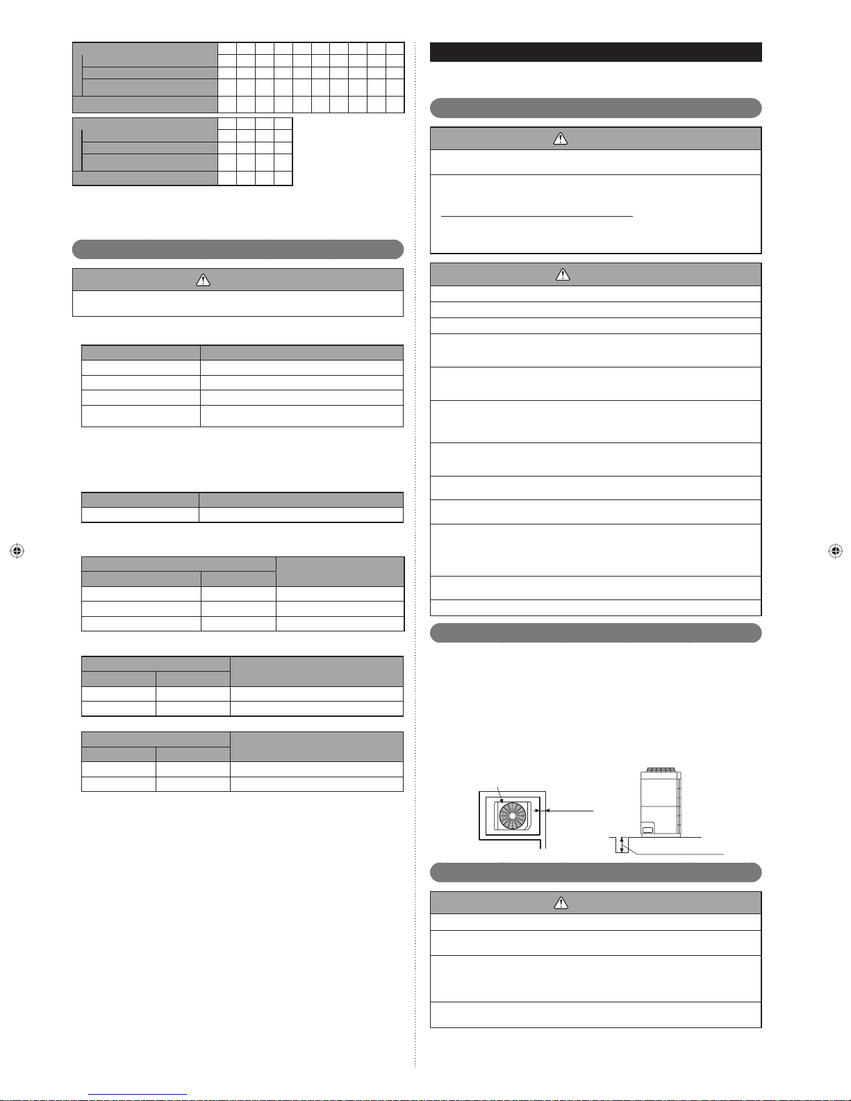
Kombination (HD) 8101216182022242628
Außengerät 1 (HD) 8 10 12 8 10 10 12 12 10 10
Außengerät 2 (HD) ---88101012810
Außengerät 3 (HD) --------88
Maximal anschließbare Innengeräte
Kombination (HD) 30 32 34 36
Außengerät 1 (HD) 10 12 12 12
Außengerät 2 (HD) 10 10 12 12
Außengerät 3 (HD) 10 10 10 12
Maximal anschließbare Innengeräte
Wenn Außengeräte angeschlossen werden, installieren Sie das Außengerät mit der größten nominalen Systemkapazität so nah wie möglich am Kältemittelrohr und Innengerät, gefolgt von denen,
mit geringeren nominalen Systemkapazitäten. (Außengerät 1 ≥ Außengerät 2 ≥Außengerät 3)
15 16 17 24 27 30 32 35 39 42
45 47 50 53
Optionale Teile2. 5.
INSTALLATIONSARBEIT3.
Bitte holen Sie sich die Genehmigung des Kunden ein, wenn Sie den Installationsort
auswählen und installieren Sie das Hauptgerät.
Einen Installationsort aussuchen3. 1.
WARNUNG
Installieren Sie das Gerät an einem Ort, der sein Gewicht aushalten kann und wo
es nicht umkippen oder herunterfallen kann.
Berechnen Sie die richtige Kältemittelkonzentration, wenn Sie es in einem ge-
schlossenen Raum installieren.
Gesamtmenge des aufgefüllten Kältemittels in Kältemitteleinrichtung (kg)
Kapazität des kleinsten Raums, wo das gerät installiert wird (m3)
Wenn die Ergebnisse der Berechnung die Konzentrationsgrenze überschreiten, erhöhen Sie den Raumoberfl ächenbereich oder installieren Sie einen Belüftungskanal.
≤
Kältemittelkonzentration (kg/m3)
(0,3kg/m3)
VORSICHT
Die folgenden Teile sind optionale Teile, speziell für das R410A Kältemittel.
Verwenden Sie keine anderen Teile als die, die unten aufgeführt sind.
Kältemittel-Abzweigungs-Gerät2. 5. 1.
Kältemittel-Abzweigungs-Gerät
UTP-RX01AH 8,0 oder weniger
UTP-RX01BH 18,0 oder weniger
UTP-RX01CH 28,0 oder weniger
UTP-RX04BH
*: Für den Fall, dass die 2 Kältemittel-Abzweigungs-Geräte in Serie geschaltet sind
(insgesamt 8 Abzweigungen), ist die maximale Kapazität der anschließbaren Innengeräte bis zu 56,0 kW.
Gesamte Kühlkapazität des Innengeräts (kW)
18,0 oder weniger (für 1 Abzweig)
56,0 oder weniger (Insgesamt 4 Abzweigungen) *
Außengerät Bausatz für Abzweig2. 5. 2.
Modell Gesamte Kühlkapazität des Innengeräts (kW)
UTP-DX567A ALLE
Separationsrohr2. 5. 3.
Modell
für 2 Rohre für 3 Rohre
UTP-AX090A , UTR-BP090X UTP-BX090A 28,0 oder weniger
UTP-AX180A , UTR-BP180X UTP-BX180A 28,1 bis 56,0
UTP-AX567A , UTR-BP567X UTP-BX567A 56,1 oder mehr
Gesamte Kühlkapazität des
Innengeräts (kW)
Kopf2. 5. 4.
Modell: für 2 Rohre
3-6 Abzweigungen
UTR-H0906L UTR-H0908L 28,0 oder weniger
UTR-H1806L UTR-H1808L 28,1 bis 56,0
3-6 Abzweigungen 3-8 Abzweigungen
UTP-J0906A UTP-J0908A 28,0 oder weniger
UTP-J1806A UTP-J1808A 28,1 bis 56,0
3-8 Abzweigungen
Modell: für 3 Rohre
Gesamte Kühlkapazität des Innengeräts
Gesamte Kühlkapazität des Innengeräts
(kW)
(kW)
VORSICHT
Wählen Sie einen Installationsort aus, indem Sie folgende Vorsichtsmaßnahmen beachten:
Installieren Sie die Gerätestufe. (Innerhalb von 3 Grad)
Installieren Sie dieses Gerät an einem Ort mit guter Belüftung.
Wenn das gerät an einem Ort installiert werden muss, der in Reichweite des
allgemeinen Publikums liegt, installieren Sie, wenn nötig, einen Schutzzaun oder
Ähnliches, um den Zugang zu verhindern.
Installieren Sie das Gerät in einem Bereich, der Ihre Nachbarn nicht stört, da sie vom Luftstrom, der aus dem Ausgang kommt, dem Geräusch oder der Vibration betroffen sein könnten.
Wenn es in der Nähe Ihrer Nachbarn installiert werden muss, sichern Sie sich ihre Zustimmung.
Wenn das Gerät in einer kalten Region installiert wird, in der es zu Schneeansammlungen, Schneefall oder Frost kommt, treffen Sie die entsprechenden Maßnahmen,
um es vor diesen Elementen zu schützen.
Um einen stabilen Betrieb sicher zu stellen, installieren Sie Ein- und Auslasskanäle.
Installieren Sie das Gerät in einem Bereich, der keine Probleme verursacht, selbst
wenn das Abwasser vom Gerät abgelassen wird. Ansonsten stellen Sie sicher, dass
das abgelassene Wasser keine Menschen oder Objekte beeinträchtigt.
Installieren Sie das Gerät in einem Bereich, der keine Heizquellen, Dämpfe hat oder an
dem es kein Risiko für das Auslaufen entzündlicher Gase in der Nachbarschaft gibt.
Installieren Sie das Gerät in einem Bereich, der nicht in der Nähe von Abgas- oder
Entlüftungsanschlüssen liegt, die Dampf, Ruß, Staub oder Rückstände ausstoßen.
Installieren Sie Innengerät, Außengerät, Netzkabel, Übertragungskabel und Fernbe-
dienungskabel mindestens in 1 Meter Entfernung zu Fernsehern oder Radios.
Dies dient der Vermeidung von TV-Empfangsstörungen und Radio-Rauschen. (Unter
bestimmten Signalbedingungen kann es auch dann zu einem verrauschten Empfang
kommen, wenn die Installation weiter als 1 Meter entfernt erfolgt.)
Halten Sie die Länge der Leitungen der Innen- und Außengeräte innerhalb des zulässigen Bereichs.
Zu Wartungszwecken graben Sie die Leitungen nicht ein.
Ablassvorgang3. 2.
Das Abwasser wird unten am Gerät abgelassen. Bauen Sie einen Abfl ussgraben •
um die Grundfl äche herum und lassen Sie das Abwasser richtig ab.
Wenn Sie das Gerät auf einem Dach installieren, führen Sie korrekt eine Bodenab-•
dichtung durch.
Ablassvorgang:
Während des Betriebs kann sich das Abwasser von der Grundfl äche des Außengeräts bilden.•
Führen Sie wenn nötig einen Ablassvorgang durch.
Wenn Sie verhindern möchten, dass das Abwasser an der Abgrenzung ausläuft, •
bauen Sie einen Graben für das Abwasser, wie in der Abbildung gezeigt wird.
Wenn nötig, stellen Sie eine Ablaufwanne bereit.•
Außengerät
50mm oder
mehr
De-3
10mm oder mehr
Installationsmaße3. 3.
VORSICHT
Wenn Sie das Außengerät installieren, achten Sie auf folgende Punkte.
Bieten Sie ausreichend Installationsraum, wie zum Beispiel Transportweg, Wartungsraum, Belüftungsraum, Kühlmittelleitungsraum und Durchgänge.
Achten Sie auf die Spezifi kationen des Installationsraums, wie in der Abbildung
gezeigt. Wenn das Gerät nicht gemäß der Spezifi kationen installiert wurde, kann es
zum Kurzschluss oder schlechter Leistung kommen. Das Gerät kann aufgrund des
Hochdruckschutzes anfällig dafür sein, in den Nicht-Betrieb zu verfallen.
Stellen Sie keine Hindernisse in die Auslassrichtung des Luftstroms. Wenn es ein
Hindernis in der Auslassrichtung gibt, installieren Sie einen Auslasskanal.
 Loading...