

Fujitsu AirStage AB12, AirStage AB24, AirStage AB14, AirStage AB18, AirStage AB30 Service Manual
...Page 1
R407C
Variable Refrigerant Flow System
Multi Air Conditioning System for Buildings
HEAT RECOVERY TYPE
Model : AO90
SERVICE MANUAL
Page 2
Multi Air Conditioning System
for Buildings
SERVICE MANUAL
Variable Refrigerant Flow System
R407C
Page 3

CONTENTS
1. TEST RUN
1-4 TEST RUN CONTROL................................................................................................
1-3-1 TEST RUN FROM OUTDOOR PC BOARD........................................................
2-2 MICROPROCESSOR FUNCTION LIST.....................................................................
2-1 PCB LAYOUTS...........................................................................................................
2. FUNCTION OF PRINTED CIRCUIT BOARD
3-1-3 3 MINUTES RESTART PREVENTION (3MIN ST)..............................................
3-1-2 COMPRESSOR OUTPUT PATTERN ................................................................
3-1-1 OPERATION / STOP CONDITION......................................................................
3-1 COMPRESSOR OPERATION CONTROL..................................................................
1-2 CHECK ITEM DURING TEST RUN............................................................................
1-1 CHECK ITEMS BEFORE TEST RUN.........................................................................
2-1-2 INDOOR UNIT CONTROL CIRCUIT BOARD
2-1-1 INDOOR UNIT CONTROL CIRCUIT BOARD.....................................................
2-1-3 OUTDOOR UNIT CONTROL CIRCUIT BOARD................................................. 02-03
WIRED REMOTE CONTROLLER, SIMPLE REMOTE CONTROLLER
CIRCUIT BOARD.................................................................................................
1-3-2 TEST RUN FROM REMOTE CONTROLLER.....................................................
2-1-4
2-2-1 INDOOR UNIT.....................................................................................................
2-2-2 OUTDOOR UNIT.................................................................................................
2-3 FUNCTION AND SETTING OF EACH SWITCH........................................................
2-3-1 INDOOR UNIT(EXCEPT FOR COMPACT WALL MOUNTED TYPE..................
2-3-2 INDOOR UNIT(COMPACT WALL MOUNTED TYPE).........................................
2-3-3 OUTDOOR UNIT..................................................................................................
2-3-4 WIRED, SIMPLE REMOTE CONTROLLER........................................................
2-4 EXTERNAL INPUT & OUTPUT..................................................................................
2-4-1 INDOOR UNIT(EXCEPT FOR COMPACT WALL MOUNTED TYPE).................
2-4-2 INDOOR UNIT(COMPACT WALL MOUNTED)...................................................
.2-4-3 OUTDOOR UNIT..................................................................................................
3. OUTDOOR UNIT OPERATION CONTROL
3-1-4 COMPRESSOR RECOVERY OPERATION........................................................
3-2 HEAT EXCHANGE CAPACITY CONTROL................................................................
3-3 OUTDOOR FAN MOTOR CONTROL........................................................................
01-01
01-02
1-3 TEST RUN METHOD.................................................................................................. 01-03
01-03
01-03
01-05
02-01
02-01
02-04
02-08
02-08
02-11
02-12
02-12
02-16
02-19
02-22
02-28
02-28
02-30
02-31
03-01
03-01
03-01
03-01
03-02
03-03
03-04
2-1-5 CENTRAL REMOTE CONTROLLER CIRCUIT BOARD......................................
02-05
2-3-5 CENTRAL REMOTE CONTROLLER.................................................................. 02-24
2-4-4 CENTRAL REMOTE CONTROLLER / PC CONTROLLER.................................
02-32
(COMPACT WALL MOUNTED TYPE)................................................................. 02-02
2-1-6 NETWORK CONVERTORS' CIRCUIT BOARD....................................................
02-06
2-3-6 NETWORK CONVERTOR.................................................................................. 02-26
2-4-5 NETWORK CONVERTOR...................................................................................
02-34
Page 4

3-10 PROTECTION FUNCTIONS......................................................................................
4. INDOOR UNIT OPERATION
3-9 OIL RECOVERY CONTROL......................................................................................
03-11
04-01
03-10
5. TROUBLESHOOTING
4-1 TIMER CONTROL......................................................................................................
4-2 FAN CONTROL..........................................................................................................
4-2-1 "AUTO" POSITION..............................................................................................
4-2-2 "LOW", "MED" AND "HIGH" POSITION..............................................................
4-3 MASTER CONTROL..................................................................................................
4-3-1 OPERATION MODE CONTROL..........................................................................
4-3-2 AUTO CHANGEOVER.........................................................................................
4-3-3 "COOL" POSITION..............................................................................................
4-3-4 "HEAT" POSITION...............................................................................................
4-3-5 "FAN" POSITION.................................................................................................
4-4 LOUVER CONTROL..................................................................................................
4-5 ENERGY SAVE OPERATION...................................................................................
4-6 ANTI FREEZE CONTROL.........................................................................................
4-7 ELECTRONIC EXPANSION VALVE CONTROL.......................................................
5-1 INDOOR UNIT............................................................................................................
5-1-1 NORMAL OPERATION DISPLAY.......................................................................
5-1-2 ABNORMAL OPERATION DISPLAY...................................................................
5-2 OUTDOOR UNIT........................................................................................................
5-2-1 NORMAL OPERATING DISPLAY........................................................................
5-2-2 ABNORMAL OPERATION DISPLAY...................................................................
5-3 REMOTE CONTROLLER...........................................................................................
5-5 ERROR CODE & TROUBLESHOOTING...................................................................
5-5-1 TROUBLE SHOOTING WITH ERROR CODE....................................................
6. APPENDING DATA 1 (INSTALLATION)
6-1 ADDITIONAL CHARGE..............................................................................................
6-2 ADDRESS SETTING..................................................................................................
5-5-2 TROUBLE SHOOTING WITH NO ERROR CODE..............................................
04-06
04-06
04-06
04-07
04-07
04-08
04-09
04-09
04-09
04-10
04-13
04-14
04-15
05-01
05-01
05-03
05-03
05-04
5-3-1 WIRED REMOTE CONTROLLER....................................................................... 05-05
5-3-2 SIMPLE REMOTE CONTROLLER...................................................................... 05-05
5-3-3 CENTRAL REMOTE CONTROLLER.................................................................. 05-06
05-05
05-10
05-10
05-36
05-02
06-01
06-02
5-4 NETWORK CONVERTOR.........................................................................................
05-09
5-6 CASE SUCH AS THESE ARE NORMAL...................................................................
05-46
3-4 EXPANSION VALVES 1 AND 2 CONTROL...............................................................
3-5 CIRCULATING SAVE AMOUNT CONTROL..............................................................
3-6 SOLENOID VALVE 2 CONTROL...............................................................................
3-7 DEFROSTING CONTROL..........................................................................................
3-8 OIL RETURN CONTROL............................................................................................
03-06
03-07
03-07
03-08
03-09
4-8 AUTO RESTART........................................................................................................
4-9 DRAIN PUMP OPERATION.......................................................................................
04-15
04-15
Page 5

7-1 REFRIGERANT PIPE SYSTEM DIAGRAM................................................................
7-3-1 INDOOR UNIT......................................................................................................
7-3-2 OUTDOOR UNIT..................................................................................................
7. APPENDING DATA 1 (UNIT)
7-2 CHARACTERISTICS OF SENSORS..........................................................................
7-2-1 THRMISTOR.........................................................................................................
7-2-2 PRESSURE SENSOR..........................................................................................
7-3 WIRING DIAGRAM.....................................................................................................
7-4 OUTDOOR INTERNAL LAYOUT................................................................................
07-01
07-02
07-02
07-04
07-06
07-06
07-18
07-19
6-2-1 KINDS OF ADDRESS AND SETTING RANGE....................................................
6-2-2 ADDRESS SETTING FOR COMPACT WALL MOUNTED
TYPE INDOOR UNIT.............................................................................................
6-3 PUMP DOWN METHOD.............................................................................................
6-3-1 START AND STOP OF THE PUMP DOWN.........................................................
6-4 TOOLS........................................................................................................................
06-02
06-04
06-09
06-09
6-3-2 A FLOW CHART OF PUMP DOWN.....................................................................
06-09
06-10
6-5 PRECAUTIONS FOR INSTALLATION.......................................................................
06-11
7-5 MODEL DESIGNATION ..............................................................................................
07-20
6-2-3 EXAMPLES OF SYSTEM SETTING.....................................................................
06-05
6-6 PRECAUTIONS FOR SERVICING.............................................................................
6-7 IN USE OF THE NEW REFRIGERANT R407C..........................................................
06-13
06-14
6-7-1 WHAT IS CFC/HCFC/HFC ?.................................................................................
6-7-2 CHARACTERISTICS OF R22 AND R407C..........................................................
06-14
06-14
6-7-3 DEFFERENCE FROM CONVENTIONAL MODEL(R22) AND PRECAUTIONS...
06-15
7-2-3 ELECTRIC EXPANSION VALVE..........................................................................
7-2-4 RB UNIT................................................................................................................
7-2-5 OTHERS...............................................................................................................
07-04
07-04
07-05
Page 6
1 . TEST RUN
TM
R407C
Page 7
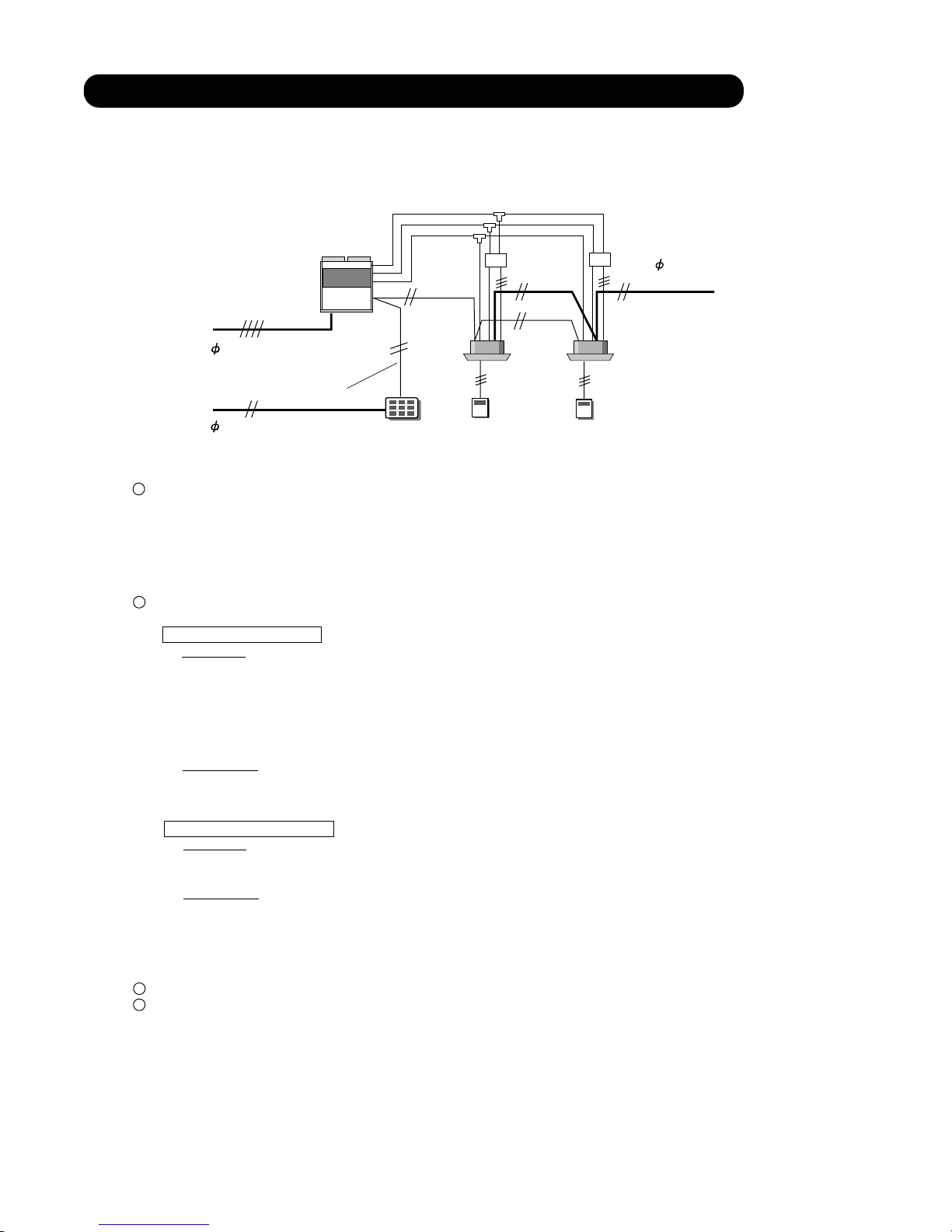
Outdoor
unit
3 4W 50Hz 380 - 415V
1 50Hz
220 - 240V
Transmission line
Indoor
unit
1
13
9
10
9
10
1
14
15 16
12
13
14
2
4
3 5 6
15
16 17 18
21
Central
remote controller
Wired
remote controller
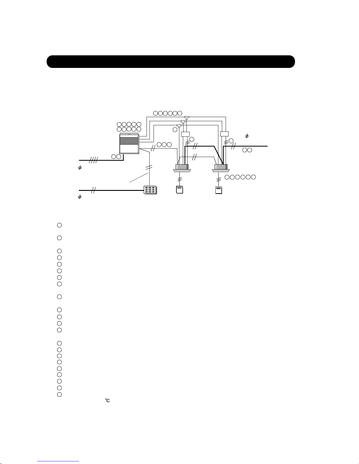
Before test run, check the following items.
Is the selection of the outdoor unit and the indoor units correct?
(Check the number of connected indoor units, total capacity of the indoor units)
Is the piping length correct?
(Ex. Maximum piping length : 100m)
Is the diameter selected separation kit correct?
Doesn't gas leak?
Have the vaccuum process done enough time?
Is the refrigerant flow correct?
1
2
Is the additional refrigerant charge amount correct?
Are the power supply cables connected?
Is the spec. for the power supply cable correct?
Is the length of the transmission line under the limit?
Is the spec. for the transmission cable correct?
(non-polar 2-core, 0.75-1.25mm )
(Note the charge amount to control box cover)
(Power supply for the indoor unit and outdoor unit is separated.)
Is the transmission cable connected to all units?
2
Is the remote controller cable connected to units?
Is not the power supply cable connected to transmission and remote controller terminal?
Are the addresses set? (Ex. Refrigerant circuit address, indoor unit address, remote controller address, etc.)
3
4
5
6
7
8
9
Is the diameter of the selected pipe correct?
10
12
13
14
15
1. TEST RUN
16
17
Have the all settings done on the PCB?
18
Is the ball valve opened?
19
Is the pipe heat-insulated which have the enough thickness?
20
Is the drain water-flow correct?
21
Is the power supplied to crank case heater for more than 12 hours before the start of test run at outdoor
temperature of 20 or below?
22
1 50Hz 220 - 240V
1-1 CHECK ITEMS BEFORE TEST RUN
01-01
7 8
19
21
22
7 20
Is the RB unit cable connected?
11
RB unit
RB unit
11
11
Page 8
1-2 CHECK ITEM DURING TEST RUN
During the test run operation, check the following items.
When the power supply turn on,check the following items.
Outdoor unit : LED 1 lights continuously.
if LED flushing, it means error occurs ,check the eroor and solve the problem.
Indoor unit : LED RED (operation lamp) & GREEN (timer lamp) lights flush alternately.(Auto restart setting:Invalidity)
RC : Timer display indicates
When errors occur, don't advance towards the following step before a complete settlement of all these errors.
Start the Indoor unit test run from remote controller one by one (Refer to 1-3-2)
Check the following item.
Indoor unit
LED (red&green) light flush at the same time slowly.
Louver operates to open.
Fan rotates
Air flow comes
(Drain pump opration)
RC signal receive
Outdoor unit
Coresponds from indoor unit signal
Compressor start to operates
Fan rotates
Measure the following item.
Indoor unit
Air intake temp.
Air flow temp.
Outdoor unit
Outdoor temp.
Discharge pipe temp.
Suction pipe temp.
High pressure
Low pressure
Contlnue the operation about 10 minutes.
When there is no ploblem, check the next indoor unit.
After every indoor unit is check by test run, please do test run using all of the indoor units and check them.
1
2
3
4
01-02
Outdoor
unit
3 4W 50Hz 380 - 415V
1 50Hz
220 - 240V
Transmission line
Indoor
unit
Central
remote controller
Wired
remote controller
1 50Hz 220 - 240V
RB unit
RB unit
All LEDs go off.(Auto restart setting : Validity)
Page 9
1-3 TEST RUN METHOD
Supply power to the crankcase heater for 12 hours prior to the start of operation if the outdoor temperature is lower
than 20 . The following is the procedure for the test run operation.
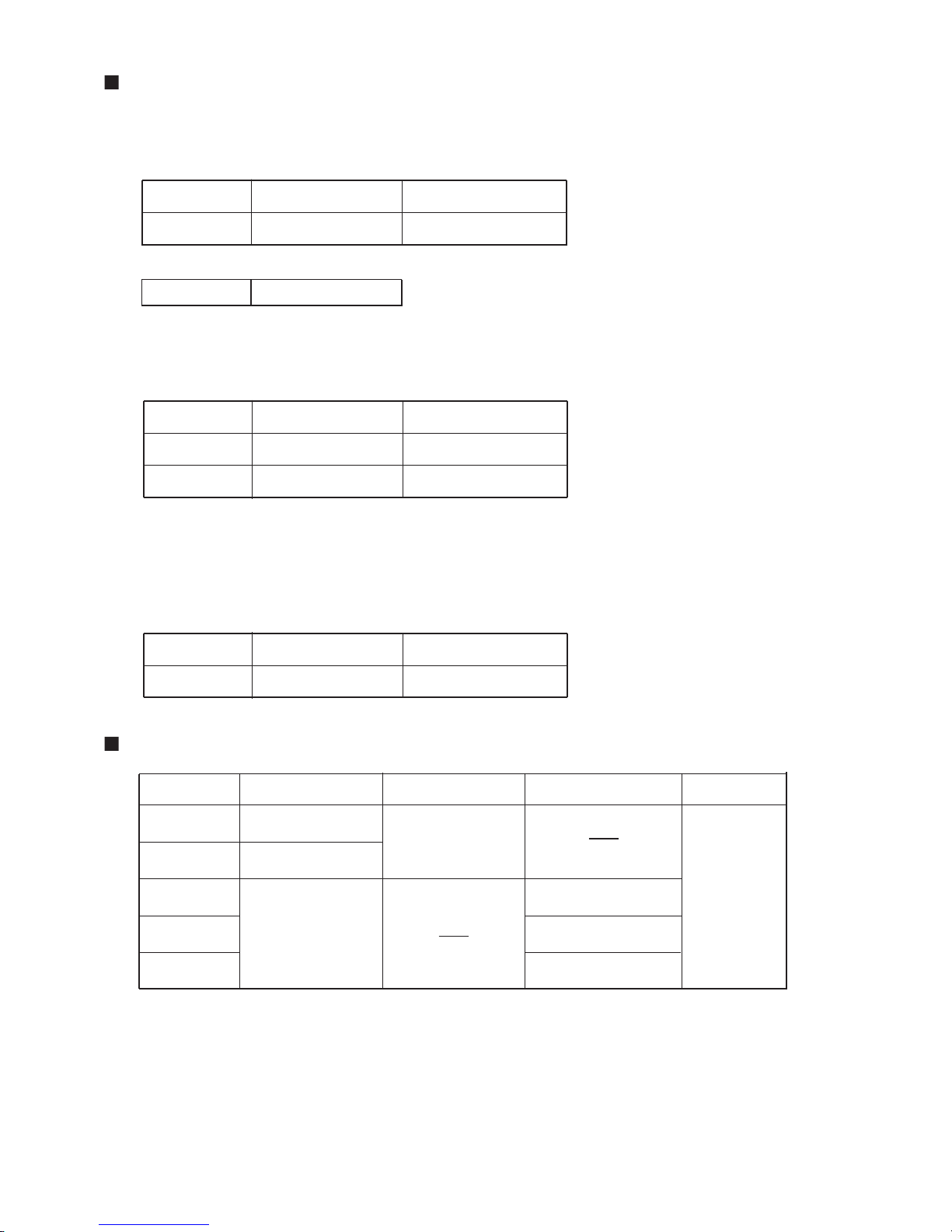
By setting DIP SW1-1 and SW1-2 on control PC board of outdoor unit, cooling test run or heating test run for all the indoor units
in the same refrigerant system can be performed.
1-3-1 TEST RUN FROM OUTDOOR PC BOARD
OFF [OFF,ON] or [ON,OFF]
SW1-2
Operation Mode
Select position of [SW1-2, SW1-1]
ON
ON
OFF
SW1-1
OFF
ON
ON
OFF
Normal Operation
Normal Operation
Heating Test Run
Cooling Test Run
[OFF,OFF]
[OFF,ON] or [ON,OFF]
[ON,ON]
[OFF,OFF]
[ON,OFF]
[OFF,OFF]
[OFF,ON]
01-03
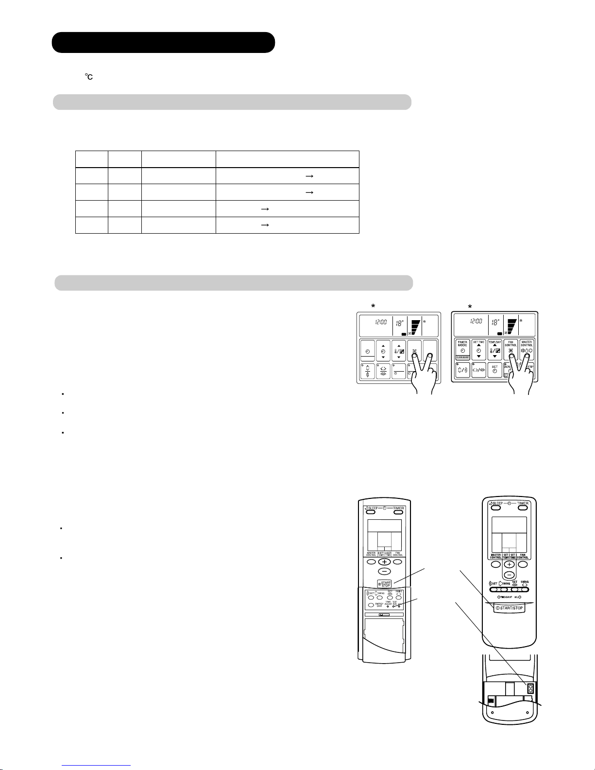
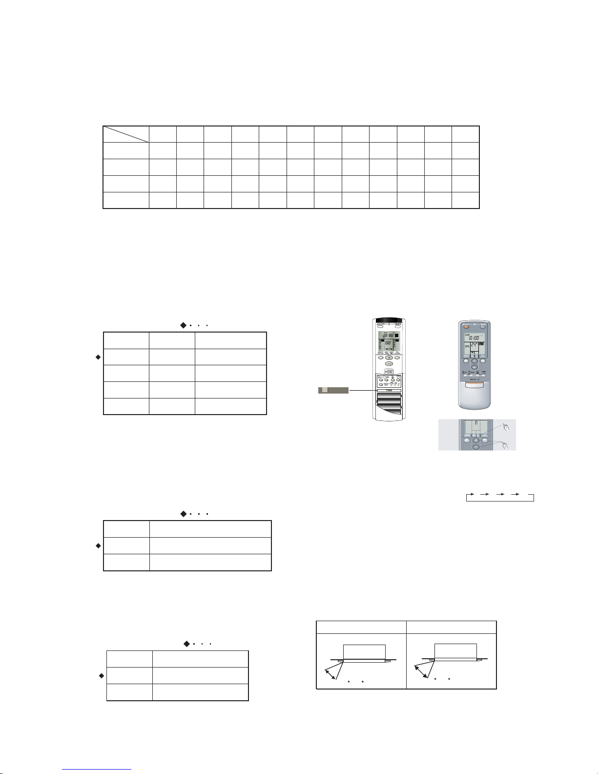
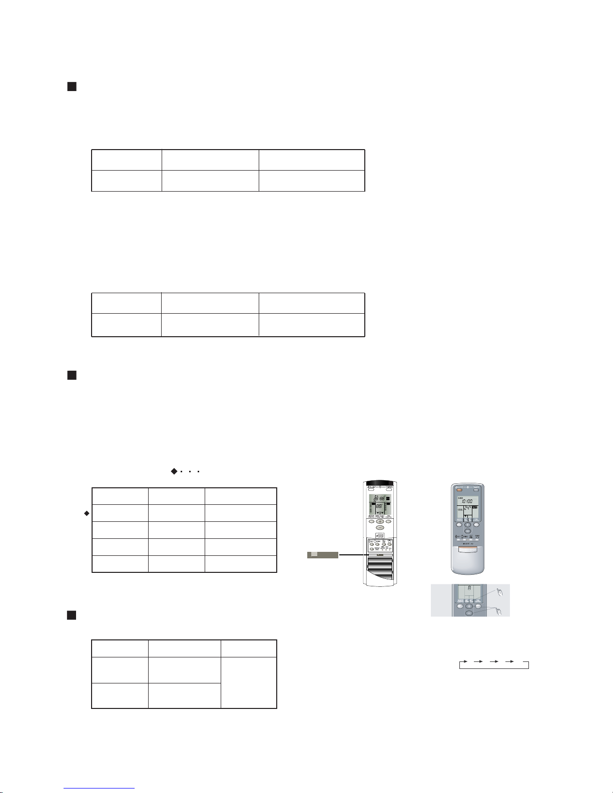
1) Standard wired remote controller
Stop the indoor and outdoor units. Push the FAN CONTROL button and
MASTER CONTROL button simultaneously for more than three seconds.
The air conditioner will start to conduct a test run and TEST will display on
the remote controller display.
However, the SET TEMP./DAY setting button does not have function,
but all other buttons, displays, and protection functions will operate.
1-3-2 TEST RUN FROM REMOTE CONTROLLER
To stop test run, push the START/STOP button of the standard wired remote
controller.
For the operation method, refer to the operating manual and perform operation
check.
Check that there are no abnormal sounds or vibration sounds during test run
operation.
2) Standard wireless remote controller
Press the test button of UTB - SA or short two pieces of metallic bodies
in the test run frame of UTB - VA, while the air conditioner is running.
To stop test run operation, push START/STOP button of the wireless
remote controller.
When the air conditioner is being test run, the OPERATION
and TIMER lamps of indoor unit flash slowly at the same time.
START/STOP button
TEST RUN button
A B C D
TEST
RUN
UTB - SA
UTB - VA
*
*
*
*
SET
MASTER
CONTROL
FAN
CONTROL
TIMER
MODE
TEMP./DAY
SET TIME
CLOCK ADJUST
OP
SET
D
ZONE
ENERG
COOL
CLOCK
C
NON STOP
TEST
COOL
CLOCK
C
NON STOP
TEST
UTB - LA
UTB - LB
Page 10
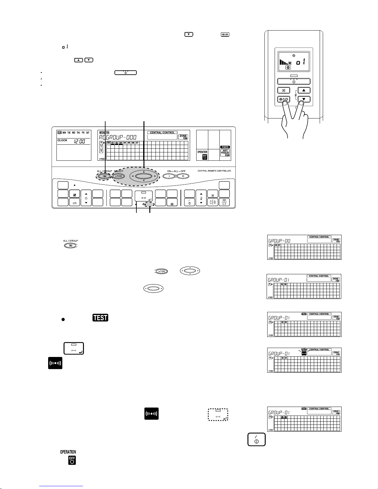
3) Simple remote controller
Stop the indoor and outdoor units. Push the remote controller
SET
button and
button
simultaneously for more than three seconds. The air conditioner will start to conduct a test
run and will display
on the temperature display.
display.
However the
setting button does not have function but all other buttons,
displays and protection functions will operate.
To stop test running press the button of the simple remote controller.
For the operation method refer to the operating manual and perform operation check.
Check that there are no abnormal sounds or vibration sounds during test run operation.
4) Central remote controller
CHECK
ACL
MASTER
ENERGY ANTI
FAN
TIMER
SET
TIMER
DELETE
TIMER
DAY
CLOCK
ADJUST
DAY OFF
TEMP.
MEMORY
OPERATION
MEMORY
TEST
SET
CENTRAL
DELETE
BACK
GROUP
ZONE
ON OFF
TIME
CONTROL
CONTROL
FILTER
RESET
CONTROL
FREEZE
COPY
TIMER
MODE
SAVE
SETTING SETTING
Remote control group operation settings are performed in the control mode. The following procedure for the setting is the same
for any of the control modes: Individual mode / Group control mode / All control grop.
Push to select control mode from among Individual control mode / Group
control mode / All control.
When Group control mode is selected use to select the desired group number,
then go to (3).
SET
60 minutes' test run starts.
To stop the test run, do the same procedure as those for stop a normal operatin.
It is possible to change the settings for the operation mode (heating / cooling) and fan setting.
Once the signal has been transmitted, the segment and LED
will go out. The indoor unit will start test run operation.
SET
If the test run is stopped midway, do the operation shown in (3) above and press ,
ON OFF
will come on, then do the operation shown in (4). Test run will stop.
When Individual control mode is selected, use and to select the desired central control number, then go to (3).
When All control mode is selected, go directly to (3).
Press TEST and will light up. The operation setting is applied to the selected
units.
Press to send the signal and test run setting is sent to the indoor unit.
will flash as the signal is being transmitted.
(1)
(2)
(3)(4)
(1)
(2)
(3)
(4)
(5)
SELECT
NOTE :
01-04
Page 11
1) When the test run signal is transmitted from standard wired, wireless remote controller, simple remote controller
and central remote controller.
(1) The test runn operation starts and the electric expansion valve is controlled to a maximum flow, regardless of
the temperature condition.
(2) De-frosting and frost prevention operation has priority over item(1).
(3) After 60 minutes passes, the test run stops. However, the operation continues in same operating mode.
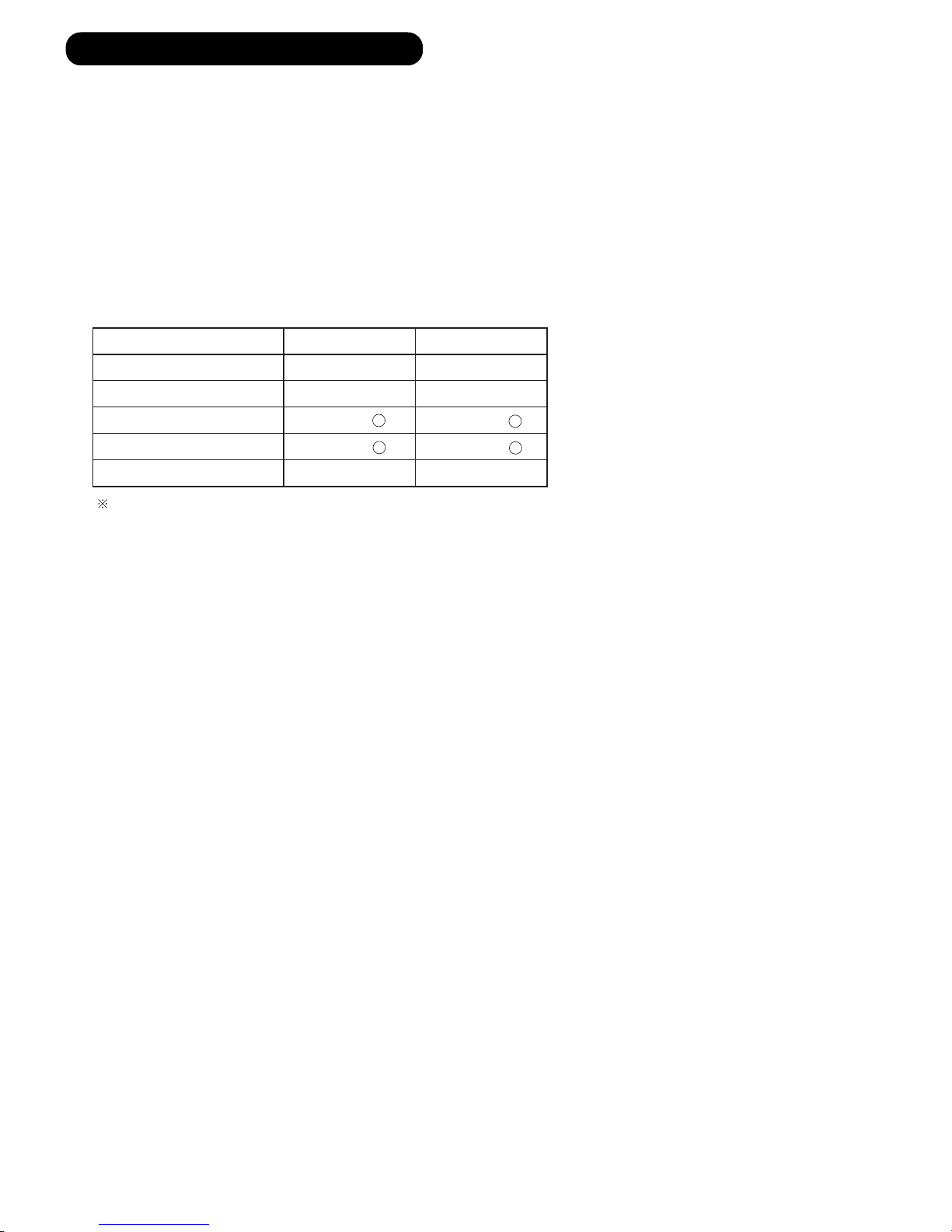
2) When the test run signal is transmitted from the outdoor unit.
(1) Whether state of the indoor unit operates or stops, All units in the same refrigerant system will start to conduct a
test run in accordance with the operation
mode set by DIP SW 1-1 and SW 1-2 of outdoor unit ( see 1 - 3 - 1 ).
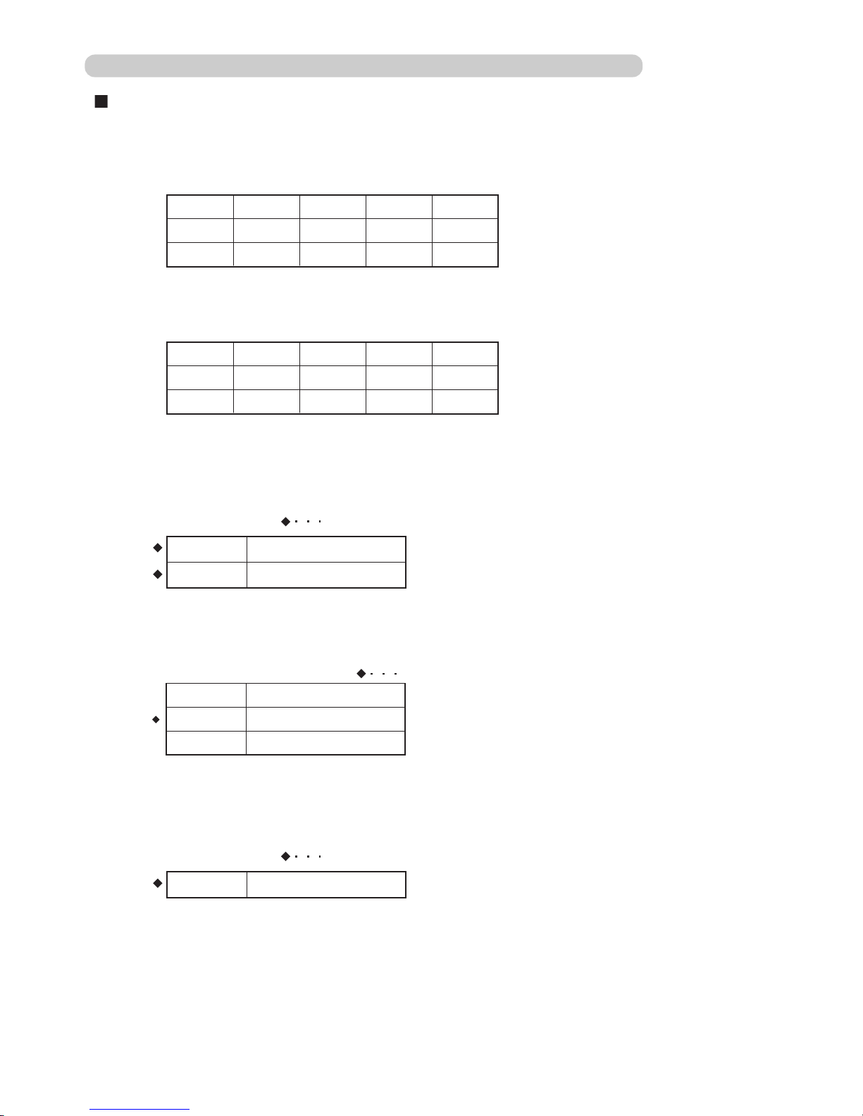
(2) Test running initialization is shown below.
Fan speed Hi Hi
Room Temperature Indication 18 30
Vertical Air Direction Panel
Horizontal Air Direction Panel
Swing
Operating Mode Cooling Heating
OFF OFF
1-4 TEST RUN CONTROL
Position
1
Position
4
Position
3
Position
3
Please refer to '4-4 LOUVER CONTROL' in this manual and find the definition
for air direction panel position.
01-05
Page 12
2 . FUNCTION OF PRINTED CIRCUIT
BOARD
TM
R407C
Page 13
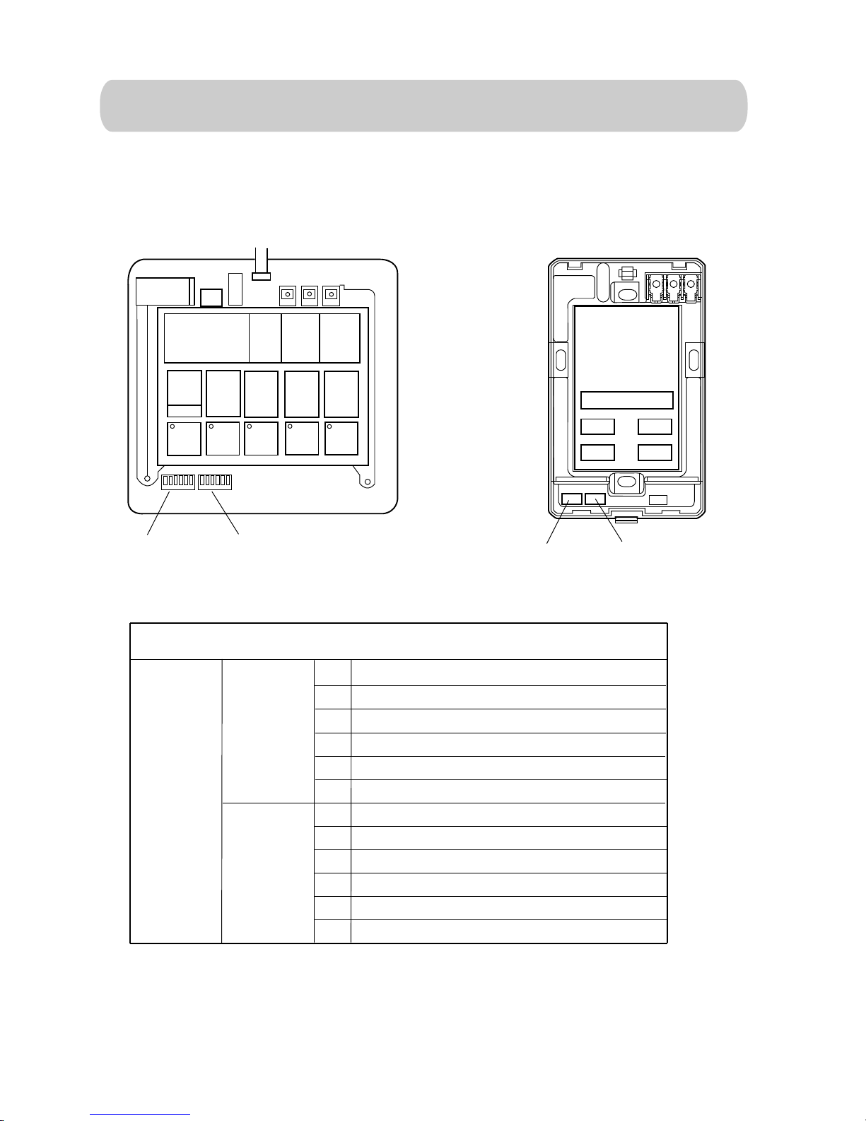
2-1 PCB LAYOUTS
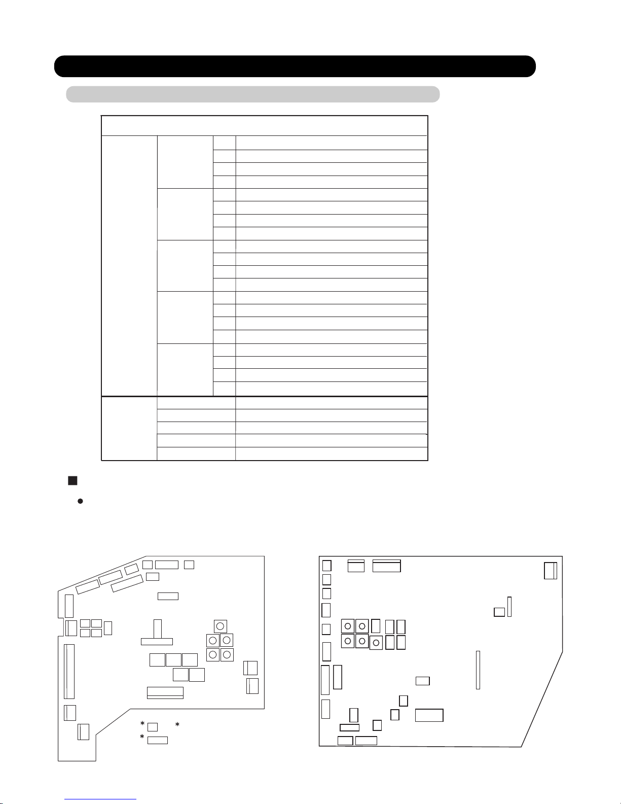
2-1-1 INDOOR UNIT CONTROL CIRCUIT BOARD
2. FUNCTION OF PRINTED CIRCUIT BOARD
02-01
Indoor unit
SW 1
SW 2
DIP SW
SW 3
SW 4
Room temp correct coefficient of heating 1
Room temp correct coefficient of heating 2
Room temp correct coefficient of cooling
Forbidden(Indoor unit fan speed switch 1)
Forbidden(Indoor unit fan speed switch 2)
Forbidden(Indoor unit fan speed switch 3)
Extermal input select edge / pulse
Forbidden(Indoor unit model code)
1
2
3
4
1
2
3
4
1
2
3
4
1
2
3
4
Filter check validity / invalidity
Forbidden(Indoor unit model code)
Forbidden(Indoor unit model code)
Forbidden(Indoor unit model code)
SW 6
SW 7
SW 8
SW 9
SW 10
Indoor unit address switch
Forbidden
Rotary SW
Forbidden
Forbidden
Forbidden
Auto restart validity / invalidity
Refrigeration circuit address 1
Refrigeration circuit address 2
Remote controller address
Indoor unit control circuit board
SWITCH POSITION
Wireless remote controller custom code switch 1
1
2
3
4
Wireless remote controller custom code switch 2
Frost prevention temperature shift switch
Draft prevention setting switch
SW 5
CN27
CN18
CN19 CN20 CN21
CN22 CN23
CN24
CN25
CN26
CN11
CN12
CN13
CN14
CN1
CN2
CN4
CN5
CN10
CN6
CN3
CN17
CN16
CN15
SW1
SW2
SW3 SW4
SW5
SW7
SW9
SW6
SW8
SW10
CN201
CN101
CN23
CN1
CN9
CN16
CN7
CN4
CN13
CN11
CN6
CN5
CN19
CN12
CN8
CN22
CN24
CN21
CN20
CN17
CN18
CN14
CN3
CN25
CN15
CN26
SW1
SW2
SW3
SW4
SW5
SW7
SW9
SW6
SW8
SW10
For AB / AU / AR types indoor unit
For AS / AW types indoor unit
CN101 and CN201 exist
in the PCB of power supply.
Page 14
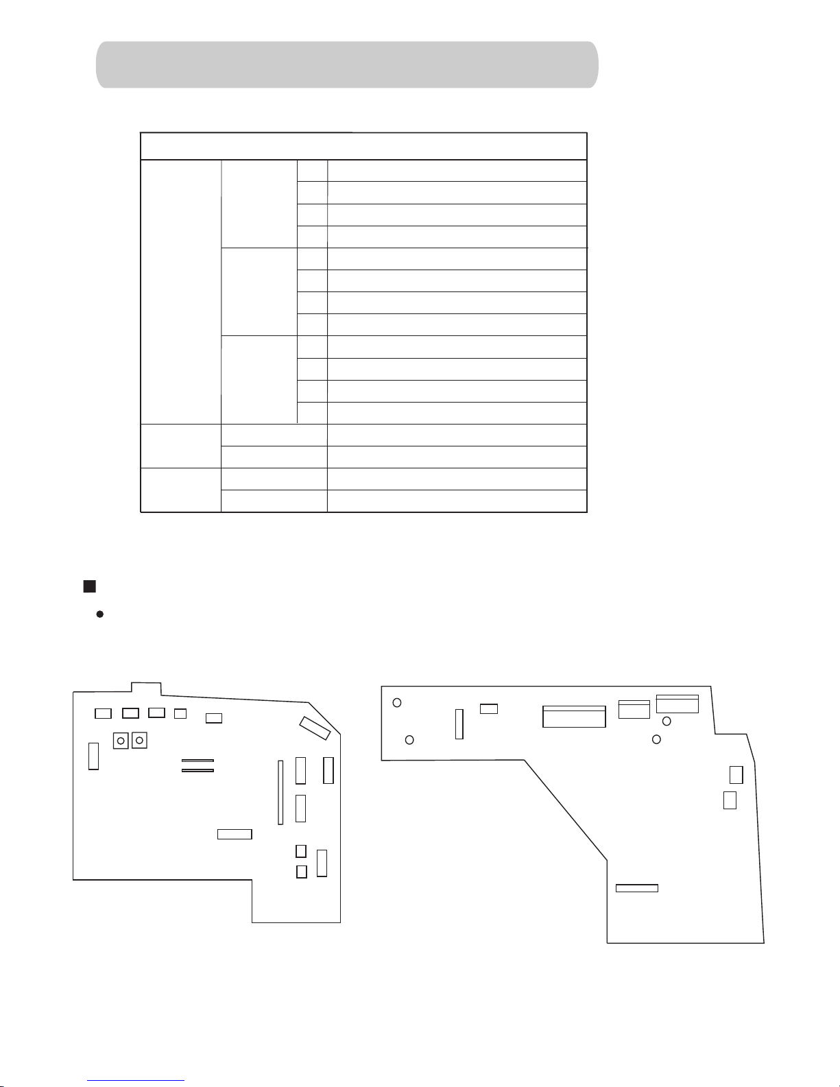
SWITCH POSITION
Compact wall mounted type indoor unit control circuit board
CN7
CN4
CN101
CN6
CN9
CN1
CN108
CN12
CN2
CN107
CN8
CN10
CN3
CN11
SW4
W101
SW5
SW1 SW2
SW3
JM1
JM2
CN104
CN105
CN102
CN103
CN106
W102
W103
W104
Controller PCB
Power supply PCB
2-1-2 INDOOR UNIT CONTROL CIRCUIT BOARD
(COMPACT WALL MOUNTED TYPE)
Indoor unit
SW 1
SW 2
DIP SW
SW 3
SW 4
Forbidden(Indoor unit fan speed switch 1)
Forbidden(Indoor unit fan speed switch 2)
Forbidden(Indoor unit model code)
1
2
3
4
1
2
3
4
1
2
3
4
Forbidden(Indoor unit model code)
Wireless remote controller custom code
Indoor unit address switch
Forbidden
Rotary SW
Forbidden
Auto restart validity / invalidity
Refrigerant circuit address switch
Refrigerant circuit address switch
SW 5
Indoor unit address switch
Refrigerant circuit address switch
Indoor unit address switch
Refrigerant circuit address switch
JM 1
JM 2
Jumper
wire
Wireless remote controller custom code
02-02
Page 15
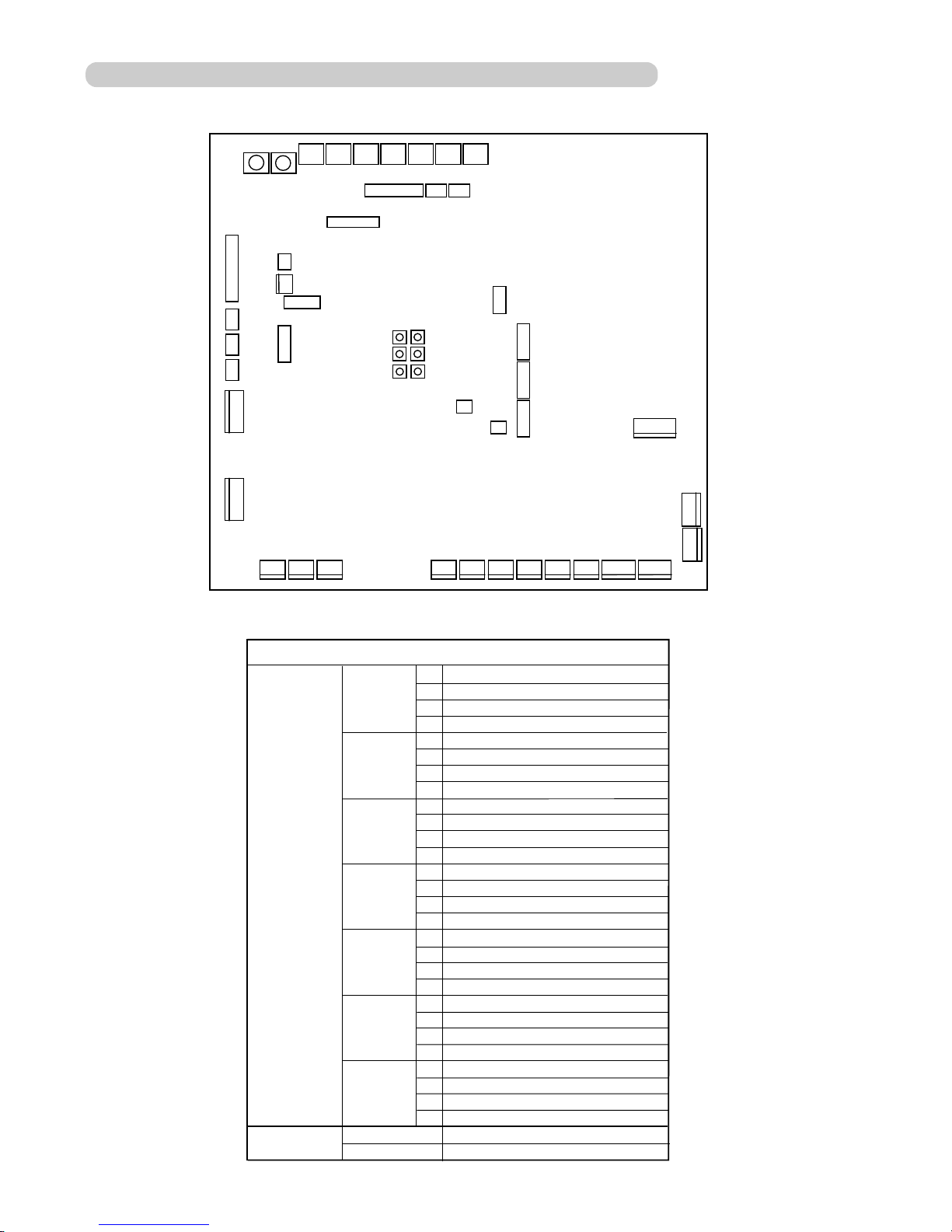
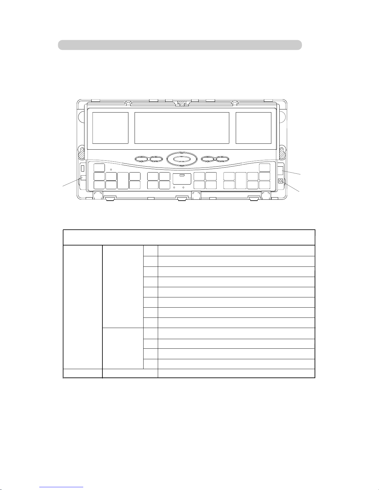
2-1-3 OUTDOOR UNIT CONTROL CIRCUIT BOARD
02-03
SW9 SW8
SW6SW7 SW5 SW4SW3 SW2 SW1
CN27 CN34
CN33
CN45
CN24
CN25
CN26
CN4
CN3
CN28
CN44
CN22
CN2
CN35
CN29
CN30
CN31
CN1
CN42
CN48
CN20
CN19
CN18 CN14
CN13 CN11 CN9 CN7
CN12 CN10 CN8
CN6
CN5
CN51
LED1
LED2
LED3
LED4
LED5
LED6
Outdoor unit
SW 1
SW 2
SW 3
SW 4
SW 5
SW 6
SW 7
1
2
3
4
1
2
3
4
1
2
3
4
1
2
3
4
1
2
3
4
1
2
3
4
1
2
3
4
Forced oil recovery operation
Forbidden
Silent operation mode
Snow falling protection fan mode
EEV initialization
System type switch 1
System type switch 2
Forbidden
SW 8
SW 9
Base heater validity / invalidity
Forbidden
Forbidden
Forbidden
Defrost temperature setting SW1
Defrost temperature setting SW2
Forbidden
Forbidden
Forbidden
Forbidden
Forbidden
Forbidden
Forbidden
Forbidden
Forbidden
DIP SW
ROTARY SW
Test run(Heating)
Test run(Cooling)
Pump down operation
Forced defrost operation
Refrigerant circuit address switch 1
Refrigerant circuit address switch 2
Forbidden
Page 16
1
2
3
4
5
6
1
2
3
4
5
6
DIP SW1
DIP SW2
O
N
O
N
Wired & Simple remote controller
SW 1
SW 2
DIP SW
Remote controller switch 1(Terminator)
Indoor unit connection (One / multiple)
Forbidden
Remote controller switch 2(Master / Slave)
Forbidden
Back ground light validity / invalidity
Maintenance switch
Forbidden
Battery backup switch
1
2
3
4
5
6
1
2
3
4
5
6
Forbidden
Cooling / Heat pump
Auto change over validity / invalidity
2-1-4 WIRED REMOTE CONTROLLER,SIMPLE REMOTE CONTROLLER
CIRCUIT BOARD
*
Simple remote
controller only
*
Wired remote
controller only
Wired remote controller
Simple remote controller
DIP SW1 DIP SW2
02-04
Page 17
DIP SW3
DIP SW2
SWITCH 42
Central remote controller
SW 2
SW 3
1
2
3
4
5
6
7
8
1
2
3
4
Filter sign indication ON / OFF
C / F switch
RC operation prohibit function validity/invalidity
Forbidden
Forbidden
SRAM battery ON / OFF
Forbidden
Forbidden
Forbidden
Forbidden
Initial setting
External input validity / invalidity
External input select edge / pulse
SW 42
DIP-SW
o
o
2-1-5 CENTRAL REMOTE CONTROLLER CIRCUIT BOARD
02-05
Page 18
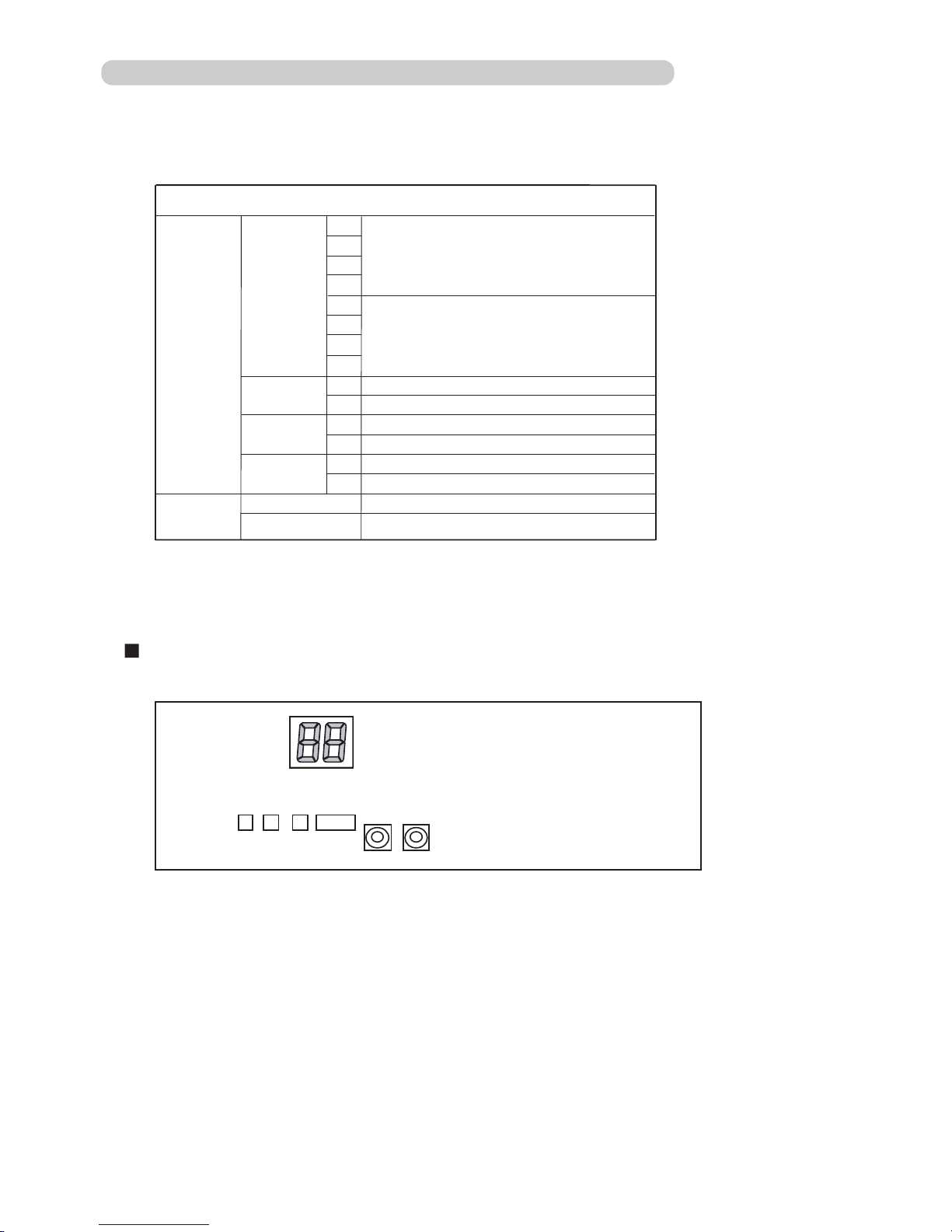
2-1-6 NETWORK CONVERTORS' CIRCUIT BOARD
02-06
Network Convertor (UTR-YSSA)
SW 103
DIP SW
SW 107
SW 109
Forbidden
Wired remote controller validity / invalidity
External input validity / invalidity
External input select edge / pulse
Auto changeover validity / invalidity
1
2
3
4
1
2
5
6
7
8
1
2
1
2
Auto restart validity / invalidity
Refrigerant circuit address 1
SWITCH POSITION
(1) NETWORK CONVERTOR (UTR-YSSA)
Remote controller type
Number of connected indoor units
SW 108
* Set to OFF for duct type indoor unit
SW 110
SW 111
ROTARY
SW
Refrigerant circuit address 2
SW111
SW109
SW103
SW107
SW110
SW108
D129
Page 19

02-07
(Switch)
SWITCH AND LED POSITION
(2) NETWORK CONVERTOR (UTR-YLLA)
Switch No.
SW1
SW2
SW3
SW4
SW5
SW6
SW7
Push switch
Push switch
Push switch
Push switch
Rotaly switch (0-15)
Rotaly switch (0-15)
Push switch
CPU Reset
Selection of setting mode
Contents
(LED)
LED No.
D9
D14
D25-D18
D29-D26
Contents
Type
Service Pin SW (VRF side)
Service Pin SW (Lon works side)
Confirmation of setting
Setting up the value at the each setting mode (D25-D22)
Setting up the value at the each setting mode (D21-D18)
Light up when SW1 is pressed (Neuron ID Transmission)
Light up when SW2 is pressed (Neuron ID Transmission)
Indicates the setting mode selected with SW3
Indicates the setting value specified with SW5 and SW6
SW3
SW4
SW5
SW6
SW7
SW1
SW2
D9
D14
D29,28,27,26(From left)
D25,24,23,22,21,20,19,18(From left)
Page 20
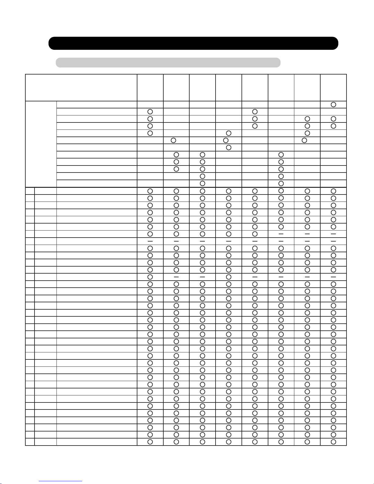
2-2 MICROPROCESSOR FUNCTION LIST
2-2-1 INDOOR UNIT
02-08
Large
Ceiling
Universal
Compact
Cassette
Thin
Cassette
Large
Cassette
Compact
Duct
Low
Static
Pressure
Duct
High
Static
Pressure
Duct
60,000
54,000
45,000
36,000
30,000
24,000 (25,000)
24 25 25
20,000
18,000
14,000
12,000
9,000
7,000
CN1 AC IN
CN2 TH. FUSE
CN3 FAN CAPA
CN4 FAN MOTOR
CN5 D. PUMP
CN6 S. VALVE
CN10 SP-M (U,D)
CN11 SP-M (R,L)
CN12 HEATER
CN13 DISPLAY
CN14 E.E.VALVE
CN15 FLOAT SW
CN16 MOTOR F. BACK
CN17 REMOCON
CN18 TEST
CN19 R. TH
CN20 P. TH
CN21 S. TH
CN22 EX. OUT1
CN23 EX. OUT2
CN24 EX. OUT3
CN25 FLASH
CN26 COMMUNICATION-PWB
CN27 EX. IN
CN101 NETWORK
CN201 COMMUNICATION
SW1 FUNCTION 1
SW2 FUNCTION 2
SW3 FUNCTION 3
SW4 FUNCTION 4
SW5 FUNCTION 5
SW6
INDOOR UNIT ADDRESS 1
SW7 FORBIDDEN
SW8
REFRIGERANT ADDRESS 1
SW9
REFRIGERANT ADDRESS 2
SW10
REMOTE CONTROLLER ADDRESS
INDOOR UNIT TYPE
CAPACITY
(BTU/h)
Page 21

02-09
Wall Mounted Ceiling Wall
30,000
24,000
18,000
14,000
CN1 TH. FUSE
CN2 FAN MOTOR
CN3 FAN MOTOR
CN4 D. PUMP
CN5 S. VALVE
CN6 DIFFUSER/SP-M(U,D)
CN7 SP-M(L/R)
CN8 DISPLAY-1
CN9 DISPLAY-2
CN10 F. BACK
CN11 TEST
CN12 E.E.VALVE
CN13 REMOCON
CN14 FLOAT
CN15 NETWORK
CN16 R.-TH
CN17 P-TH
CN18 S-TH
CN19 FLASH
CN20 HEATER
CN21 EX. IN
CN22 EX. OUT1
CN23 EX. OUT2
CN24 EX. OUT3
CN25 COMMUNICATION-PWB
CN26 COMMUNICATION
SW1 FUNCTION 1
SW2 FUNCTION 2
SW3 FUNCTION 3
SW4 FUNCTION 4
SW5 FUNCTION 5
SW6 INDOOR UNIT ADDRESS 1
SW7 FORBIDDEN
SW8 REFRIGERANT ADDRESS 1
SW9 REFRIGERANT ADDRESS 2
SW10 REMOTE CONTROLLER ADDRESS
INDOOR UNIT TYPE
CAPACITY
(BTU/h)
Page 22
02-10
Compact Wall Mounted
14,000 ○
CAPACITY 12,000 ○
(BTU/h) 9,000 ○
7,000 ○
CN1 POWER-PWB ○
CN2 FAN F. BACK ○
CN3 E. E. VALVE ○
CN4 SP MOTOT(U,D) ○
CN5 DISPLAY ○
CN6 ROOM TH. ○
CN7 PIPE TH. ○
CN8 TEST ○
CN9 FLASH ○
CN10 EX. IN ○
CN11 EX. OUT ○
CN12 COMMUNICATION-PWB ○
CN101 MAIN-PWB ○
CN102 FAN MOTOR ○
CN103 TRANS-P ○
CN104 TRANS-S ○
CN105 TH. FUSE ○
CN106 S. VALVE ○
CN107 NETWORK ○
CN108 COMMUNICATION ○
W101-102 POWER SUPPLY ○
W103-104 FAN CAPACITOR ○
SW1 FUNCTION ○
SW2 FUNCTION & INDOOR UNIT ADDRESS ○
SW3 REFRIGERANT CIRCUIT ADDRESS ○
SW4 INDOOR UNIT ADDRESS ○
SW5 REFRIGERANT CIRCUIT ADDRESS ○
JM1
WIRELESS REMOTE CONTROLLER CUSTOM CODE
○
JM2
WIRELESS REMOTE CONTROLLER CUSTOM CODE
○
INDOOR UNIT TYPE
Page 23

AO*90MPCMFOUTDOOR UNIT TYPE
CN1
AC IN
CN2
NET
CN3
FAN.1
CN4
FAN.2
CN5
BASE HEATER
CN6
CRANK CASE HEATER
CN7
CN8
S.V.1
CN9
S.V.2
CN10
S.V.3
CN11
S.V.4
CN12
S.V.5
S.V.8
S.V.6
S.V.7
CN13
CN14
CN19
CN20
TERMINATOR
CN22
COMP.1
CN24
COMP.2
CN25
COMP.3
CN26
TH.1
CN27
FLASH W/R M
FLASH W/R S
CN28
CN29
E.E.V.3
E.E.V.1
E.E.V.2
CN30
P.SEN-H
P.SEN-M
CN31
P.SW-H
CN33
TEST
CN34
TH.2
CN35
CN42
CN44
EXT.OUTPUT
CN45
CN48
COMMUNICATION PWB
CN51
SW 1
FUNCTION 1
SW 2
FUNCTION 2
SW 3 FUNCTION 3
SW 4 FUNCTION 4
SW 5 FUNCTION 5
SW 6 FUNCTION 6
SW 7
2-2-2 OUTDOOR UNIT
SW 8
SW 9
REFRIGERANT
ADDRESS 2
REFRIGERANT
ADDRESS 1
CN18
4WV.2
4WV.3
4WV.4
FUNCTION 7
02-09
Page 24
2-3 FUNCTION AND SETTING OF EACH SWITCH
2-3-1 INDOOR UNIT
02-12
1-2 Room temperature correct coefficient of heating.
Decide the heating temperature correct coefficient value of heating.
2-1 Room temperature correct coefficient of cooling.
Decide the cooling temperature correct coefficient value of cooling.
HEATING TEMPERATURE CORRECTION
Coefficient value
OFF
ON
+ 4 deg
SW1-3
SW1-4
+ 8 deg
OFF
ON OFF
0 deg
OFF
+ 12 degON ON
COOLING TEMPERATURE CORRECTION
Coefficient value
0 deg
SW2-1
ON + 2 deg
OFF
2-2 Dip SW 2-2 setting forbidden
OFF
SW2-2
2-3 Filter check validity / invalidity.
Filter check is set with Dip SW 2-3
FILTER CLEANING FUNCTION
Filter check
Invalidity
SW2-3
ON Validity
OFF
DIP SWITCH SETTING
1. SW1 setting
2. SW2 setting
( Factory setting)
( Factory setting)
( Factory setting)
( Factory setting)
2-4 Auto restart validity / invalidity.
Control the auto restart function by turning this switch ON/OFF.
AUTO RESTART SETTING
Auto restart
Validity
SW2-4
ON
Invalidity
OFF
( Factory setting)
1-1 DIP SW 1-1 and SW 1-2 setting forbidden
OFF
SW1-1
( Factory setting)
OFF
SW1-2
Page 25
02-13
3-1 Indoor unit fan speed switch
This switch can select fan speed corresponding to each model.
Large ceiling type
OFF
OFF
OFFSW3-1
SW3-2
OFF ON
OFF ON
OFF
OFF ON
OFF
SW3-3
ON
Cassette type
OFF
AB30
AB36 AB45
AB54
SW3-1
SW3-2
SW3-3
AU54
AU45
AU36 AU30
AU25
OFF
OFF
ON
OFF
OFF
OFF
ON
OFF
OFF
OFF
ON
OFF
ON
ON
AU20
ON
ON
ON
3. SW3 setting (Never change at the site)
Wall mounted type
OFF OFFSW3-1
SW3-2
ON
OFF ON
SW3-3
AS18
AS24 AS30
Ceiling wall type
OFF
OFFSW3-1
SW3-2
ON
OFF ONON
OFF
SW3-3
ON
AW14
AW18 AW24
AW30
ON
ON
ONON
ONON
ON
ON
SW3-1
SW3-2
SW3-3
OFF
OFF
OFF
Other model (Default)
3-2 DIP SW 3-4 setting
SW3-4
External input select
OFF
ON
Edge
Pulse
( Factory setting)
This switch is used to select the format of external input command as shown in
the table below.
OFF
OFF
OFF ON
OFF
AW7
AW9 AW12
ON
OFF
OFF
OFF
Page 26
02-14
Indoor unit model code.
This switch for changing the model code information of indoor unit PCB.
INDOOR UNIT MODEL CODE
SW4-1
SW4-2
Type
SW4-3
60
ON
OFF
ON
ON
54
OFF
OFF
ON
ON
45
ON
OFF
OFF
ON
36
OFF
OFF
OFF
ON
30
ON
ON
ON
OFF
25(24)
OFF
ON
ON
OFF
20
ON
ON
OFF
OFF
18
OFF
ON
OFF
OFF
14
ON
OFF
ON
OFF
12
OFF
OFF
ON
OFF
9
ON
OFF
OFF
OFF
7
OFF
OFF
OFF
OFF
SW4-4
Capacity
5-2 Frost prevention temperature shift switch
4. SW4 setting (Never change at the site)
5. SW5 setting
5-1 Wireless remote controller custom code switch
Decid the custom code and restrict the type of infrared control signal, in order to prevent
mixing of multiple indoor unit signals.
Remote controller custom code switch
OFFOFF
SW5-1
OFFON
Type A
Custom code
ON
ON
ON
SW5-2
Type B
Type C
Type D
( Factory setting)
5-3 Draft prevention setting switch (only for cassette type)
Set the frost prevention temperature for indoor
unit.
Frost prevention temperature shift switch
NormalOFF
SW5-3
HighON
Frost prevention temperature
( Factory setting)
OFF
C
O
O
L
FA
N
H
E
A
T
A
U
T
O
A
U
T
O
H
I
G
H
M
E
D
LO
W
T
I
M
E
R
T
I
M
E
R
R
E
S
E
T
C
L
O
C
K
S
L
E
E
P
E
N
E
R
G
Y
S
A
V
E
C
A
M
P
M
O
N
O
F
F
O
F
F
O
N
H
M
A B C D
A B C D
D
R
Y
ABCD
Remote controller
Remote controller
signal selector
switch
Set the flap angle of cassette type unit.
Draft prevention switch
Normal positionOFF
SW5-4
Draft prevention positionON
flap angle
( Factory setting)
Normal position Draft prevention position
35 - 65
25 - 65
Flap angle Flap angle
*If air conditioning cooling operation is performed in
long time and a humid place, there is a possibility
that waterdrop may hang down from a blow-off mouth.
An air flow direction, by moving the flap angle horizontally,
It can prevent that a cold wind directly hits.
1. Press the MASTER CONTROL button for
more than five seconds to start the code
change.
2. Press the (+) or (-) button to select the
desired code.
3. Press the MASTER CONTROL button again
to end the code change.
A B C D
Page 27
02-15
ROTARY SWITCH SETTING
EXTERNAL INPUT AND OUTPUT
Indoor unit address switch
Sets the indoor unit addresses.
INDOOR UNIT ADDRESS SWITCH
Refrigerant circuit address switch
Sets the refrigerant circuit.
REFRIGERANT CIRCUIT ADDRESS SWITCH (Factory setting SW 8: 0 SW 9: 0)
Remote controller address switch
REMOTE CONTROLLER ADDRESS SWITCH (Factory setting : 0)
When the indoor unit is wired by remote controller group, to identity the indoor unit in the remote
controller group, the number (remote controller address) in the remote controller group is set.
Set the remote controller address in the 0.1.2,~,15 order (Blank is not allowed)
1.SW6 setting
2.SW7 setting forbidden
Rotary SW7 0
Rotary SW
6
Description Remarks
Indoor unit
address SW
Indoor unit address
( 0~15 )
Rotary SW
8
9
Description Remarks
Refrigerant circuit
address 1
Refrigerant circuit
address 2
Refrigerant circuit
address (the first digit)
Refrigerant circuit
address (the second digit)
Rotary SW
10
Description Remarks
Remote controller
address SW
Remote controller
address
3.SW8,9 setting
4.SW10 setting
(Factory setting : 0)
Connector
CN21
CN27
Input
Output
OPERATION DISPLAY
(DC12V)
Remarks
Indoor unit type
Wall mounted /
Ceiling wall types
CN22
CN23
CN24
Other types
All types
CONTROL INPUT
(OPERATION / STOP)
ERROR DISPLAY
(DC12V)
INDOOR UNIT FAN
STATUS DISPLY(DC12V)
See 2-4-1
for details
Page 28
1-2 Model code setting switch
The model code infomation corresponding to each model is provided with the switch.
2-1 Dip SW 2-1,2-2 setting forbidden
OFF
SW2-1
2-3 DIP SW 2-4 setting forbidden.
DIP SWITCH SETTING
1. SW1 setting (Never change at the site)
2. SW2 setting
1-1 Fan speed setting switch
( Factory setting)
( Factory setting)
The fan speed corresponding to each model is set with the switch.
OFFSW1-1
SW1-2
OFF
ON ONOFF
ON
OFF ON
AS7
AS9 AS12
AS14
OFFSW1-3
SW1-4
OFF
ON ONOFF
ON
OFF ON
AS7
AS9 AS12
AS14
OFF
SW2-2
2-2 Auto restart validity / invalidity.
The auto restart function be comes validity by changing the switch position from OFF to ON.
AUTO RESTART SETTING
Auto restart
Validity
SW2-3
ON
Invalidity
OFF
( Factory setting)
OFF
SW2-4
2-3-2 INDOOR UNIT ( COMPACT WALL MOUNTED TYPE )
02-16
Page 29
3-1 Refrigrant circuit address switch
By combined with Rotary SW5 , the refrigerant circuit address (0-99) can be set.
Please see "6-2 ADDRESS SETTING" for refrigerant address conversion table.
OFF
OFF
16 - 31
32 - 47
ON
OFF
OFF
ON
OFF
48 - 63
Remarks
3. SW3 setting
( Factory setting)
SW3-1 SW3-2 SW3-3
Refrigerant
circuit address
0 - 15
64 - 79
80 - 95
96 - 99
ON
ON
OFF
ON
ON
ON
OFF
OFF
OFF
OFF
OFF
OFF
ON
ON
About Rotary
SW5,
see next page
3-2 DIP SW 3-4 setting forbidden.
( Factory setting)
OFF
SW3-4
02-17
Page 30
ROTARY SWITCH SETTING
JUMPER WIRE
Indoor unit address switch
Set the indoor unit addresses.
INDOOR UNIT ADDRESS SWITCH
Refrigerant circuit address switch
By combined with DIP switch 3-1,3-2 and 3-3,the refrigerant circuit address(0 - 99)can be set.
Please see "5-3-3 ADDRESS SETTING" for the refrigerant address conversion table.
REFRIGERANT CIRCUIT ADDRESS SWITCH (Factory setting SW 5: 0)
1.SW4 setting
Rotary SW
4
Description Remarks
Indoor unit
address SW
Indoor unit address
( 0~15 )
Rotary SW
5
Description Remarks
Refrigerant circuit
address SW
About DIP switch 3-1,3-2
and 3-3 see previous page
2.SW5 setting
(Factory setting : 0)
Wireless remote controller custom code switch
Limit the type of infrared control signal which the indoor unit is controlled,in order to prevent
misoperation of the unit due to the signal from other wirless remote controller.
Remote controller custom code switch
ConnectConnect
JM 1
ConnectDisconnect
Type A
Custom code
Disconnect
Disconnect
Disconnect
JM 2
Type B
Type C
Type D
( Factory setting)
Connect
C
O
O
L
FA
N
H
E
A
T
A
U
T
O
A
U
T
O
H
I
G
H
M
E
D
L
O
W
T
I
M
E
R
T
I
M
E
R
R
E
S
E
T
C
L
O
C
K
S
L
E
E
P
E
N
E
R
G
Y
S
A
V
E
C
A
M
P
M
O
N
O
F
F
O
F
F
O
N
H
M
A B C D
A B C D
D
R
Y
ABCD
Remote controller
Remote controller
signal selector
switch
1. Press the MASTER CONTROL button for
more than five seconds to start the code
change.
2. Press the (+) or (-) button to select the
desired code.
3. Press the MASTER CONTROL button again
to end the code change.
A B C D
02-18
EXTERNAL INPUT AND OUTPUT
Control Input
CN10
Connector
CN11
See 2-4-2
for details.
Remarks
Operation Display
Input or Output
(Operation / Stop)
(DC12V)
Page 31
2-3-3 OUTDOOR UNIT
02-19
1. SW1 setting
1-1 Test run
By setting DIP SW1-1 and SW1-2 on control PC board of outdoor unit, cooling test run or heating test run for all the indoor
units in the same refrigerant system can be performed.
SELECTOR SWITCH FOR TEST RUN AND NORMAL OPERATION
1-2 Pump down operation
Pump down operation is set with SW1-3
1-3 Forced defrost operation
PUMP DOWN OPERATION
FORCED DEFROST OPERATION
2-1 Silent operation mode (cooling mode only)
Noise level can be reduced using silent operation mode when the outdoor temperature decreases
decreases below 30 C.
2. SW2 setting
SILENT OPERATION MODE
Silent operation mode
Release
SW 2-1
ON Oparate
OFF
2-2 Snow falling protection fan mode
When snowing , to prevent the unit from being covered with snow , the outdoor fan is periodically
operated by this switch even when the compressor is stopped.
SNOW FALLING PROTECTION SW
Snow falling protection fan mode
Release
SW2-2
ON
Operate
OFF
SW1-2 SW1-1 Test Run Remarks
OFF OFF Normal operation
OFF ON Cooling test run
ON OFF Heating test run
ON ON Normal operation
SW1-3 Pump down operation Remarks
OFF Release
ON Operate
OFF ON and be kept at ON position
for more than 30 sec.
SW1-4 Forced defrost Remarks
OFF Release
ON Operate
DIP SWITCH SETTING
( Factory setting)
( Factory setting)
( Factory setting)
( Factory setting)
( Factory setting)
[OFF,OFF] [OFF,ON] and be kept at
[OFF,ON] position for more than 1 min.
[OFF,OFF] [ON,OFF] and be kept at
[OFF,ON] position for more than 1 min.
OFF ON and be kept at ON position
for more than 10 sec.
Page 32

02-20
2-3 Expansion valve initialization
This switch initializes the number of pulses of the expansion valve when the outdoor unit is stopped.
3. SW3 setting
ELECTRONIC EXPANSION VALVE INITIALIZATION
Initialization
Release
SW2-3
ON Operate
OFF
2-4 Forced oil recoverry operation.
Oil recovery is started manually by DIP SW 2-4 on the PCB.
FORCED OIL RECOVERY
Forced oil recovery
Release
SW2-4
ON Operate
OFF
( Factory setting)
( Factory setting)
Dip SW3-1,3-2,3-3 and SW3-4 setting forbidden
4.SW4 setting
4-1 Defrost temperature setting SW
OFF
SW3-1
SW3-4
SW3-2
OFF
OFF
SW3-3 OFF
The thershold temperature for starting a defrosting operation can be selected by setting up the switches.
SW4-1
SW4-2
ON
OFF
OFF
ON
OFF ON
ON OFF
Temperature
Standard
Low
High
Lower
DEFROST TEMPERATURE
( Factory setting)
4-2 Dip SW4-3 and SW4-4 setting forbidden.
OFF
OFF
SW4-3
SW4-4
5. SW5 setting
5-1 Dip SW 5-1,SW5-2 and SW5-4 setting forbidden
5-2 Base heater validity/invalidity
This switch sets the output of the base heater (CN5) on the PCB.
Base heater
Invalidity
SW5-3
ON validity
OFF
BASE HEATER SWITCH
The base heater output turns ON at an outside temperature of 2 C or less
during heating operation.
Base heater : 220-240V AC , 35W , field supplied.
( Factory setting)
Remarks
OFF ON and be kept at ON position
for more than 10 seconds
Page 33

02-21
DIP SW 6-1,SW6-2,SW6-3 and SW6-4 setting forbidden
6. SW6 setting
7. SW7 setting
7-1 System type switches
ON
ON
OFF
OFF
SW7-1 System type SW7-2
ON
OFF
OFF
ON
Forbidden
Heat recovery
Forbidden
SYSTEM TYPE SWITCHES
7-2 Dip SW 7-3 and SW 7-4 setting forbidden
( Factory setting)
Forbidden
OFF
OFF
SW7-3
SW7-4
SW8,9 setting
Rotary SW
8
9
Description Remarks
Refrigerant circuit
address 1
Refrigerant circuit
address 2
Refrigerant circuit
address (the first digit)
Refrigerant circuit
address (the second digit)
ROTARY SWITCH SETTING
CN48
OutputConnector
Error Display
(DC12V)
EXTERNAL OUTPUT
OFF
OFF
SW6-1
SW6-2
OFF
OFF
SW6-3
SW6-4
Page 34

2-3-4 WIRED , SIMPLE REMOTE CONTROLLER
1. SW1 setting
1-1 Remote controller switch 1
1-4 Remote controller switch 2
1-3 DIP SW1-3 setting forbidden
REMOTE CONTROLLER SWITCH 2
Setting for Master/Slave
OFF Master
SW1-4
ON Slave
REMOTE CONTROLLER SWITCH 1
Terminator setting
Not terminated
SW1-1
ON
Terminated
OFF
1-2 Number of indoor unit connection (One/Multiple)
This is switched according to the number of connected indoor units.
NUMBER OF INDOOR UNIT CONNECTION
Number of indoor unit
One unit connection
SW1-2
ON Multiple unit connection
OFF
DIP SWITCH SETTING
SW 1-5 OFF
SW 1-6 OFF
SW 1-3 OFF
This is used to set up the terminated resistance of the wired remote controller.
When 1 remote controller is connected to remote controller group, set this ON all the time.
When 2 remote controllers are connected to remote controller group, set the Master one OFF, and set the Slave one ON.
If it is used to set up Master/Slave setting of wired remote control.
When 1 remote control is connected to 1 remote control group, always set the Master OFF.
When 2 remote controls are connected to remote control group, set one side to Master, and the other side to Slave.
1-5 DIP SW 1-5 and SW 1-6 setting forbidden.
( Factory setting)
( Factory setting)
( Factory setting)
02-22
Page 35

02-23
2-1 Cooling only / heat pump
Switching cooling only / heat pump.
COOLING ONLY / HEAT PUMP SWITCH
Operation system
Heat pump/Heat recovery
SW2-1
ON Cooling only
OFF
2-2 Auto change over validity/invalidity
Selecting auto change over validity/invalidity.
Never turn it on in the case of Heat pump type.
2. SW2 setting
AUTO CHANGE OVER
Auto change over
Invalidity
SW2-2
ON Validity
Invalidity
Validity
OFF
2-4 Maintenance switch
Used to indicate of the refrigerant system, indoor unit address.
MAINTENANCE SWITCH
Mode
Normal mode
SW2-4
ON Maintenance mode
OFF
2-6 Battery backup switch (Wired remote controller only)
When installing, turn the SW2-6 ON.
2-5 DIP SW 2-5 setting forbidden.
SW 2-5 OFF
2-3 Back ground Light validity (simple remote controller only)
Selecting to use internal background light validity/invalidity.
The background light can turn on during indoor unit operation.
BATTERY BACKUP SWITCH
Battery backup
SW2-6
ON
OFF
Never turn it ON in the case of simple remote controller.
SW 2-3
OFF
ON
Background light
Invalidity
Validity
Never turn it ON in the case of wired remote controller.
( Factory setting)
( Factory setting)
( Factory setting)
( Factory setting)
( Factory setting)
Page 36

02-24
1-1 DIP SW2-1 setting .
For validity / invalidity the external input function.
1-4 DIP SW2-4 setting.
SW2-4
ON
OFF
1-3 DIP SW2-3 setting.
Filter check sign indication
Non-Display
SW2-3
ON Display
OFF
1-5 DIP SW2-5 setting
SW 2-1 External input function
OFF Invalidity
C / F
C
F
RC operation prohibit function
Validity
SW2-5
ON Invalidity
OFF
1. DIP-SW2 SETTING
2-3-5 CENTRAL REMOTE CONTROLLER
Filter check sign indication or not when filter check come from indoor unit.
C / F switch
Temperature display is centigrate( ) / Fahrenheit( )
C
F
For validity / invalidity the wired and wireless remote controller operation prohibit function.
( Factory setting)
( Factory setting)
( Factory setting)
ON
Validity
( Factory setting)
1-2 DIP SW2-2 setting .
Select the external input command function.
SW 2-2 External input select
OFF Edge
ON
Pulse
( Factory setting)
(Refer to 2-4-4 about external input & output)
Page 37

02-25
1-6 DIP SW2-6 and 2-7 setting forbidden.
1-7 DIP SW2-8 setting.
SRAM Battery
SW2-8
ON
OFF
SW 2-6 OFF
SW 2-7 OFF
SRAM Battery ON / OFF
When installing the control remote controller, this switch must be set to ON.
(factory setting:OFF)
OFF
ON
At the time of shipment,the battery is turned off to avoid electricity consumption.
Be sure to set this switch to ON.
1-8 SW42 Initial setting button
( Factory setting)
This switch is used when initializing the central remote controller.
Page 38

2-3-6 NETWORK CONVERTOR
02-26
2. DIP- SW103 (5, 6, 7, 8) setting
Number of the connected indoor units
Number of
connected the
Indoor unit
OFF
OFF
OFF OFF
OFF OFF
OFF ON
OFF OFF
ON OFF
1
2
3
4
5
6
OFF
OFF
ON ON
OFF ON
OFF OFF
OFF ON
OFF ON
DIP-SW 103
5
6
7
8
Number of
connected the
Indoor unit
OFF
ON
ON OFF
OFF ON
ON ON
ON OFF
OFF OFF
7
8
9
10
11
12
ON
OFF
OFF ON
ON OFF
ON OFF
ON OFF
ON ON
DIP-SW 103
5
6
7
8
Number of
connected the
Indoor unit
ON
ON
OFF OFF
ON ON
OFF ON
ON ON
ON OFF
13
14
15
16
ON
ON
ON ON
DIP-SW 103
5
6
7
8
3. DIP SW 107 Setting
3-1 DIP SW 107-1 setting forbidden
Select the wired remote controller validity / invalidity
Wired remote controller
SW 107-2
OFF
ON
Wired remote controller
Invalidity
validity
( Factory setting)
( Factory setting)
Set the DIP-SW 103 (5, 6, 7, 8) according to number of the connected indoor units.
3-2 Wired remote controller validity / invalidity
SW 107-1 OFF
( Factory setting)
(1) Network convertor (UTR-YSSA)
1. Dip SW103 ( 1, 2, 3, 4) setting
Indoor unit model type and remote controller type
Indoor unit type
Heat pump of big multi type
Heat pump of single spilt type
Cooling only of single spilt type
Cooling only of big multi type
Cooling only of single spilt type
Wall mounted with wired RC
RC type
With weekly timer
With weekly timer
Without weekly timer
With weekly timer
With weekly timer
Without weekly timer
RC number
EZ-099DHSE-*,EZ-000DHSE-*,EZ-0001HSE-*,
EZ-000GHSE-*,EZ-00004HSE-*,
EZ-00005HSE-*,EZ-0015HSE-*,EZ-0019HSE-*
EZ-0994HSE-*,EZ-000EHSE-*
EZ-09503HSE-*,EZ-0950DHSE-*
EZ-099CWSE-*,EZ-000AWSE-*,EZ-0001WSE-*,
EZ-000FWSE-*,EZ-0012WSE-*
EZ-09906WSE-*,EZ-000FWSE-*
EZ-095YWSE-*
EZ-098VWSE-*
OFF OFF
OFF OFF
Without weekly timer
Heat pump of single spilt type
DIP-SW103
1
2 3
4
OFF OFF
OFF ON
OFF OFF
ON OFF
ON
OFF
OFF OFF
ON OFF
OFF ON
ON OFF
ON OFF
ON ON
OFF OFF
Set Dip SW103 ( 1, 2, 3, 4) according to indoor unit type and remote
controller (packaged together with the unit) type. You can also set
DIP-SW103 (1, 2, 3, 4) using the remote controller number that is
shown on the rear surface of the remote controller.
Rear View
EZ-########-R
RC Number
Instead of using the remote controller that was packaged together
with the unit, a VRF type remote controller must be used to
connected to network.
( Factory setting)
Asterisks (*) are used in place of variable characters.
Page 39
02-27
4. DIP SW 108 setting
4-1 External input validity / invalidity
Select the external input function validity / invalidity
SW 108-1
OFF
ON
External input function
Invalidity
validity
4-2 External input command type
Select the external input command type
SW 108-2
OFF
ON
External input command type
Edge
Pulse
( Factory setting)
( Factory setting)
5. DIP SW109 setting
5-1 Auto changeover validity / invalidity
Select auto changeover function validity / invalidity
SW 109-1
OFF
ON
Auto changeover function
Invalidity
validity
5-2 Auto restart validity / invalidity
Select auto restart function validity / invalidity
SW 109-2
OFF
ON
Auto restart function
Invalidity
validity
( Factory setting)
( Factory setting)
Page 40

2-4 EXTERNAL INPUT & OUTPUT
2-4-1 INDOOR UNIT ( EXCEPT FOR COMPACT WALL MOUNTED TYPE
02-28
(1) Control input (Operation/Stop)
Indoor unit can be operated or stopped by using indoor unit PCB
CN 21 (Wall mounted type / ceiling wall type) or CN27 (other types)
Dip SW3-4 Input select
OFF
ON
Edge
Pulse
1 Input select
2 In the case of "Edge" input
CONNECTOR INPUT SIGNAL COMMAND
Ch1 of
CN21 (RED)
or
CN27 (RED)
OFF ON
ON OFF
Operation
Stop
*1)
*2)
1
2
CN 21(RED) *1)
or
CN 27(RED) *2)
3
Ch 2
Ch 1
*1) For Wall mounted type / Ceiling wall type.
*2) For other types
Ch1 of
CN21 or
CN27
*1)
*2)
3 In the case of "pulse" input
CONNECTOR INPUT SIGNAL COMMAND
OFF ON Operation
Stop
CN21 (RED)
or
CN27 (RED)
*1)
*2)
Ch1
Ch2
OFF ON
On
On
Off
Remote
Controller
Indoor
Unit
NOTE
1. The last command has priority.
2. The indoor units within the same
remote controller group operates
in the same mode.
3.The wire connection shall be
separate from the power cable line.
Operation
Stop
CN21
or
CN27
*1)
*2)
On
Off
Indoor
Unit
Operation
On
Off
Ch1
Ch2
The width of pulse must be longer than 200ms.
Stop
Page 41
02-29
(2) Output
1 Operation display
CONNECTOR OUT VOLTAGE STATUS
Operation12V
0V
12V Error
Stop
CN22
CN23
CN24
0V
12V
0V
Normal
Fan stop
Fan run
1
2
CN 23
(WHITE)
+
-
Error
Indicator
1
2
CN 24
(WHITE)
+
-
Indoor unit
fan status
Indicator
Operation
Stop
CN 22
CN 23
CN 24
Indoor
unit
Indoor
unit
Indoor
unit
1
2
CN 22
(WHITE)
+
-
Operation
Indicator
12V
0V
Error
Normal
12V
0V
Fan run
Fan stop
12V
0V
(3) Parts
Following cord (service parts) is required. Please use the parts number shown below
to order the cord from your sales representative.
Name and shapes Q'ty Parts No.
1
1
EXTERNAL
INPUT WIRE
EXTERNAL
INPUT WIRE
9368778002
9368779009
2 Error display
3 Inter locking output with indoor unit fan
EX) Used for inter lock energize for exhaust fan.
Usage
For output port
For control
input port
Page 42

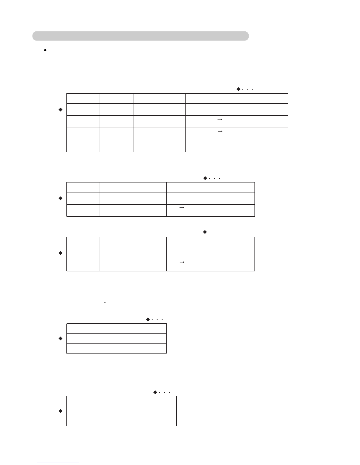
(1) Control input (Operation/Stop)
Indoor unit can be operated or stopped by using the connector CN10(RED) ON indoor unit PCB.
1
CN 10
(RED)
3
Ch 1
Ch1 of
CN10
*1)
On
On
Off
Remote
Controller
Indoor
Unit
NOTE
1. The last command has priority.
2. The wire connection shall be
separate from the power cable line.
Operation
Stop
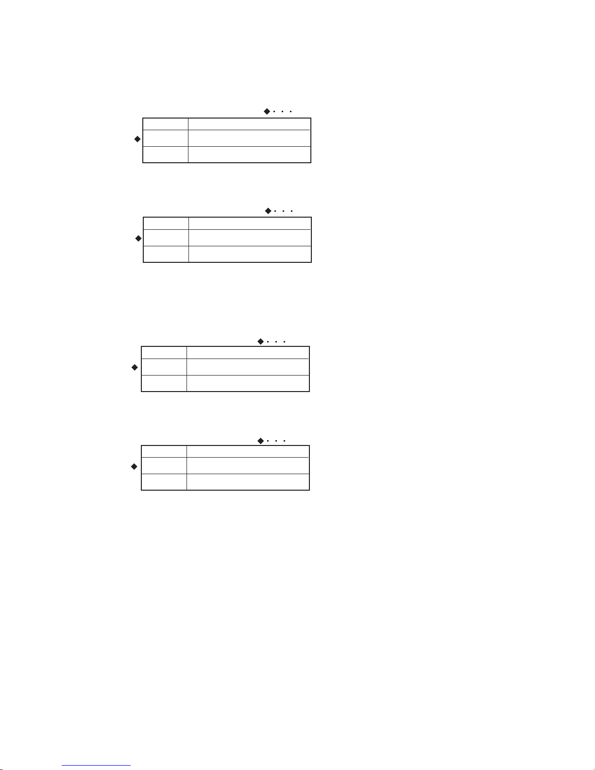
(2) Output
1 Operation display
CONNECTOR OUT VOLTAGE STATUS
Operation12V
0V Stop
CN11
Operation
Stop
CN 11
Indoor
unit
1
2
CN 11
(WHITE)
+
-
Operation
Indicator
12V
0V
(3) Parts
Following cord (service parts) is required. Please use the parts number shown below
to order the cord from your sales representative.
Name and shapes Q'ty Parts No.
1
1
EXTERNAL
INPUT WIRE
EXTERNAL
INPUT WIRE
9368778002
9368779009
Usage
For output port
For control
input port
2
2-4-2 INDOOR UNIT (COMPACT WALL MOUNTED)
02-30
(WHITE)
INPUT SIGNAL COMMAND
OFF ON
CONNECTOR
CN10
(RED)
ON OFF
Operation
Stop
Page 43
02-31
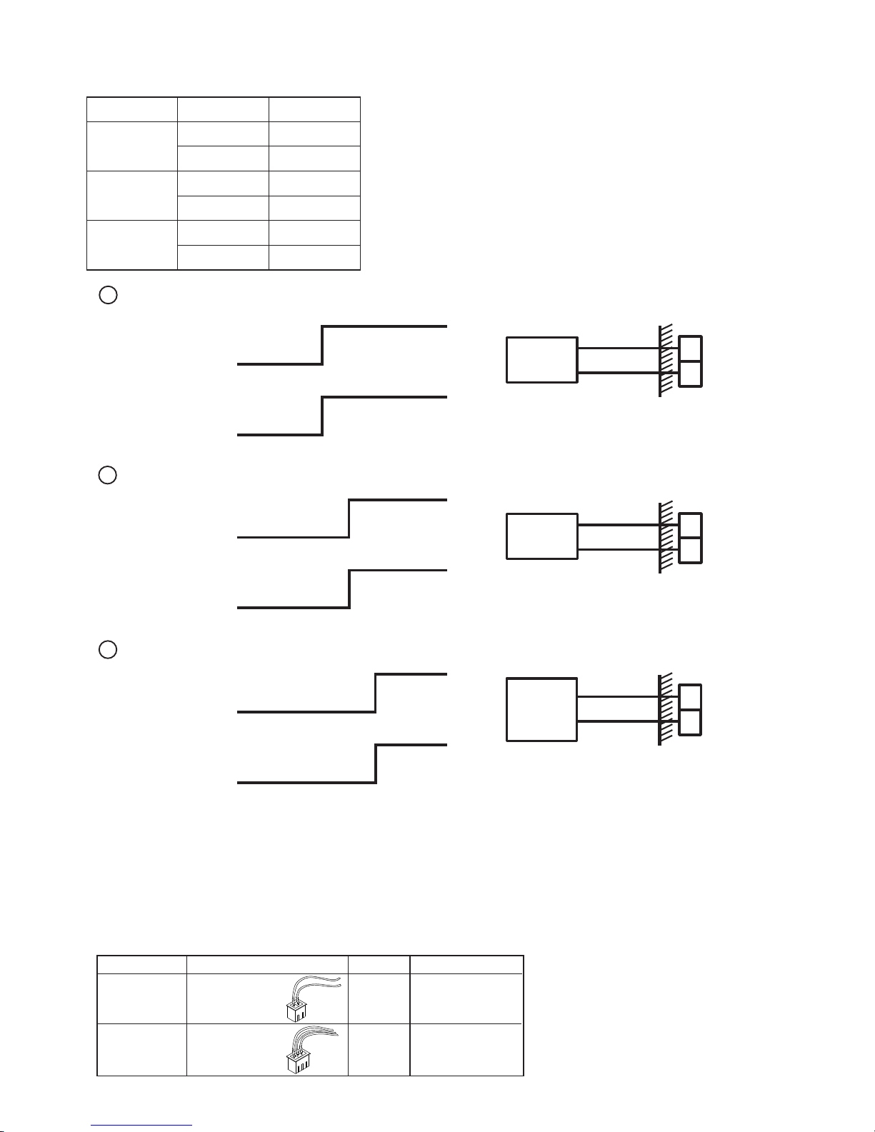
2-4-3 OUTDOOR UNIT
(1) Output
This output indicates the outdoor unit and connected indoor
unit's "Normal" or "Error" status.
1
2
CN 48
(BLACK)
+
-
Error
Indicator
1 Error display
P.C.B
CONNECTOR OUTPUT VOLTAGE STATUS
2 Base heater output
Turn ON when the ambient temperature is low in heating mode.(2 C or less)
1
2
CN 5
(GREEN)
Following cord (service parts) is required. Please use the parts number shown below
to order the cord from your sales representative.
Name and shapes Q'ty Parts No.
1 9368776008
(2) Parts
1 9368777005
EXTERNAL
INPUT
WIRE
BASE
HEATER
WIRE
CN48
(BLACK)
Normal
Error
0V
12V
Normal
12V
0V
CN48
Error
3
4
Usage
For base heater
output port
For error display
output port
Base heater
(Field supply)
AC220-240V,35W
Page 44

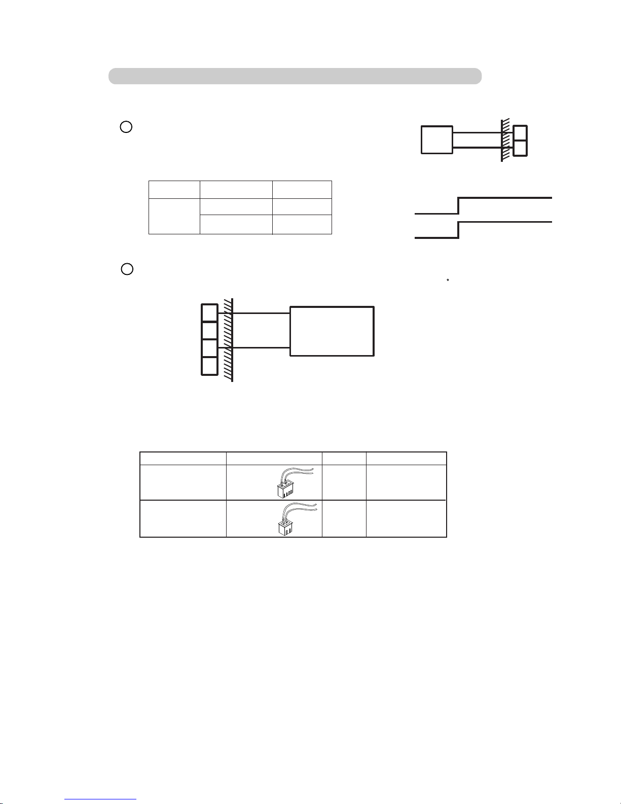
02-32
(1) Input
Indoor units which stored into Central R.C. or PC controller can be operated
or stopped by this input.
CN9
Ch1
Indoor
Unit
Control input (All on / All off)
All ON
CN9
(RED)
DipSW2-1
a) Input select
Central remote controller
PC controller
Input select can be set in environmental set up.
(Please refer to PC Controller's setting manual.)
b) In the case of "Edge" input
CONNECTOR INPUT SIGNAL COMMAND
CN9
(RED)
All ON
All OFF
OFF ON
ON OFF
On
Off
CN9
Ch1
Indoor
Unit
All ON
All OFF
c) In the case of "Pulse" input
DipSW2-2 Input select
"Edge"
"Pulse"
ON
ON
CN9
Ch2
1
OFF
ON
Ch1
CONNECTOR INPUT SIGNAL COMMAND
CN9
(RED)
All ON
All OFF
OFF ON
Ch1
Ch2
OFF ON
All ON
On
Off
On
Off
The width of pulse must be longer than 300ms.
Ch1
1
2
3
P.C.B
Ch2
2-4-4 CENTRAL REMOTE CONTROLLER / PC CONTROLLER
Page 45

02-33
(2) Output
This output indicates the indoor unit's "Operate" or "Stop" status.
Indoor
Unit
ON
OFF
Short
Open
CN1
Ch1
Operation display
Ch1
1
2
3
CN1
(WHITE)
P.C.B
Open
Short
CN1
(WHITE)
All of indoor units "OFF"
At least one more indoor units "ON"
Ch2
CONNECTOR
OUTPUT
SIGNAL
STATUS
Ch1
ON /OFF
Indicator
Error
Indicator
Com
Error display
This output indicates the indoor unit's "Normal" or "Error" status.
CN1
(WHITE)
All of indoor units "Normal"
At least one more indoor units "Error"
CONNECTOR STATUS
Ch2
Indoor
Unit
Error
Normal
CN1
Ch2
1
2
(3) Parts
Following cord (service parts) is required. Please use the parts number shown below
to order the cord from your sales representative.
9368779009
Name and shapes Q'ty Parts No.
1
EXTERNAL
INPUT
WIRE
* 1
* 2
* 1 Always insert a diode on both ends of relay coil.
* 2 Pin 1 - Pin 3 Max 15V
Pin 2 - Pin 3 70mA
OUTPUT
SIGNAL
Open
Short
Short
Open
Usage
For input and
output port
Page 46

02-34
(1) Control input
(Operation / Stop)
Indoor units that connected to network convertor can be controlled (all operation / all stop
by this input.
CN105
Ch1
Indoor
Unit
All operation
CN105
(RED)
DipSW108-1
a) Input select
b) In the case of "Edge" input
CONNECTOR INPUT SIGNAL COMMAND
CN105
(RED)
All operation
All stop
OFF ON
ON OFF
ON
OFF
CN105
Ch1
Indoor
Unit
All operation
All stop
c) In the case of "Pulse" input
DipSW108-2 Input select
"Edge"
"Pulse"
ON
ON
CN105
Ch2
OFF
ON
Ch1
CONNECTOR INPUT SIGNAL COMMAND
CN105
(RED)
All operation
All stop
OFF ON
Ch1
Ch2
OFF ON
All stop
On
Off
On
Off
The width of pulse must be longer than 200ms.
Ch2
3
2
1
P.C.B
Ch1
2-4-5 NETWORK CONVERTOR
SW111
SW109
SW103
SW107
SW110
SW108
D129
. . .
. . .
. . .
CN105(RED)
CN108(BLK) CN109
EXT IN
EXT OUT1
EXT OUT2
3 2 1
1 2 3
1 2 3
The connector positions and pin number of
network convertor (UTR-YSSA) for external
input and output are shown in the right figure.
Page 47

02-35
(2) Output
This output indicates the indoor unit's "Operation" or "Stop" status.
Indoor
Unit
Operation
Stop
Short
Open
CN108
(BLK)
Operation display (EXT OUT1)
CN108
(BLK)
P.C.B
Open
Short
CN108
(BLACK)
Indoor units "Stop"
Indoor units "Operation"
CONNECTOR
OUTPUT
SIGNAL
STATUS
ON /OFF
Indicator
Com
Error display (EXT OUT2)
This output indicates the indoor unit's "Normal" or "Error" status.
CN109
(WHITE)
All of the indoor units "Normal"
At least one more indoor units "Error"
CONNECTOR STATUS
Indoor
Unit
Error
Normal
CN109
(WHITE)
1
2
(3) Parts
Following cord (service parts) is required. Please use the parts number shown below
to order the cord from your sales representative.
9368779009
Name and shapes Q'ty Parts No.
1
EXTERNAL
INPUT
WIRE
* 1
* 2
* 1 Always insert a diode on both ends of relay coil.
* 2 Pin 2 - Pin 3 Max 15V, 50mA
OUTPUT
SIGNAL
Open
Short
Short
Open
2
1
3
CN109
(WHITE)
P.C.B
Error
Indicator
Com
* 1
* 2
* 1 Always insert a diode on both ends of relay coil.
* 2 Pin 2 - Pin 3 Max 15V, 50mA
2
1
3
Usage
For control
input and output port
Page 48

3 . OUTDOOR UNIT OPERATION
CONTROL
TM
R407C
Page 49

3-1 COMPRESSOR OPERATION CONTROL
3. OUTDOOR UNIT OPERATION CONTROL
3-1-1 OPERATION / STOP CONDITION
Compressor operation condition
When cooling requirement capacity or heating requirement capacity from either of the indoor units in the same
refrigerant system is input, the compressor operates.
But in the following case, the compressor operates in accordance with operation of each mode.
During 3 minute restart prevention operation
During compressor recovery operation
During deicing operation
Failure (except for a part)
Defrosting
Oil recovery
Under expansion valve initialization
At protective operation
Central discharge temperature protection
High pressure protection
Compressor stop condition
When all the indoor units in no "cooling requirement capacity" or "heating requirement capacity ",
all the compressors
are stopped.
But, in the following case, the compressor operates in accordance with operation of each mode.
Defrosting
Oil recovery
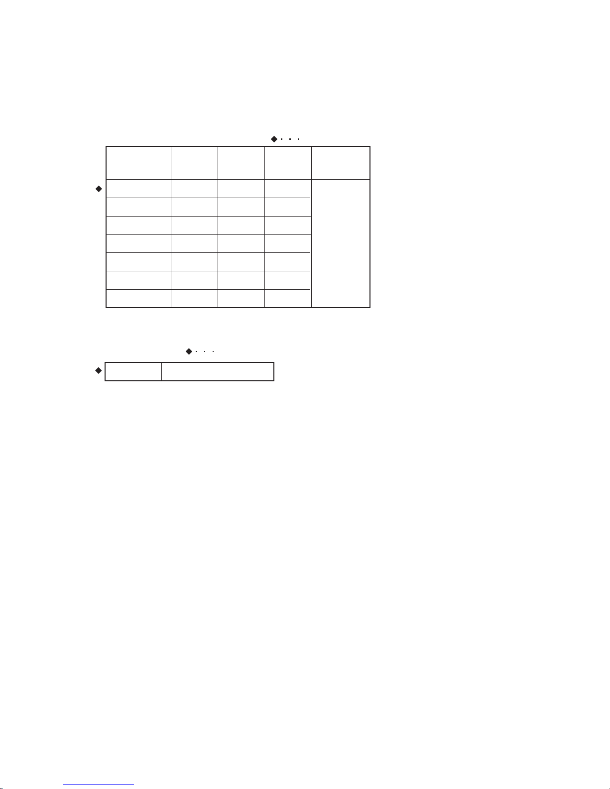
3-1-2 COMPRESSOR OUTPUT PATTERN
The output pattern of a compressor is defined as below.
OUTPUT PATTERN
COMPRESSOR 1
(2HP)
COMPRESSOR 2
(4HP)
COMPRESSOR 3
(6HP)
Step 0
Step 1
Step 2
Step 3
Step 4
Step 5
Step 6
Step 7
OFF
ON
OFF
ON
OFF
ON
OFF
ON
OFF
OFF
ON
ON
OFF
OFF
ON
ON
OFF
OFF
OFF
OFF
ON
ON
ON
ON
Compressor output pattern
3-1-3 3 MINUTES RESTART PREVENTION (3 MIN ST)
When the compressor is stopped, the compressor does not start on any condition for 3 minutes afterwards.
But, this function is excluded when defrosting, oil recovery is performed and the power is turned on.
03-01
Page 50

If compressor 1, 2, or 3 fails, or if two compressors fail at the same time, the remaining compressor(s)
perform recovery operation to prevent interruption of air conditioning system operation by a failure.
When compressor 1, 2, or 3 is judged to be faulty, the system is operated by switching the compressor output
pattern (compressors 0 to 6) as shown in the following table.
Compressor failure is displayed by LEDs on the PCB of the outdoor unit and by output ERROR to the
communication bus line (standard wired remote controller, central remote controller, PC controller).
(a) When compressor 1 (2 HP) fails (compressor 2 is substituted for compressor 1)
(b) When compressor 2 (4 HP) fails (compressor 3 is substituted for compressor 2)
(c) When compressor 3 (6 HP) fails (compressor 1 and 2 are substituted for compressor 3)
Compressor recovery operation
ORDINARY OPERATION
RECOVERY OPERATION
(a)X-4-6 (b)2-X-6 (c)2-4-X
Step 0
Step 1
Step 2
Step 4
Step 5
Step 6
Step 7
Step 0
Step 2
Step 2
Step 4
Step 6
Step 6
Step 6
Step 0
Step 1
Step 4
Step 4
Step 5
Step 5
Step 5
Step 0
Step 1
Step 2
Step 3
Step 3
Step 3
Step 3
(d)X-X-6
Step 0
Step 4
Step 4
Step 4
Step 4
Step 4
Step 4
(e)X-4-X
Step 0
Step 2
Step 2
Step 2
Step 2
Step 2
Step 2
3-1-4
COMPRESSOR RECOVERY OPERATION
03-02
*
The character X represents the compressor(s) which was(were) stopped by a protection
function or compressor error while the number(s) represent(s) capacity (in horse power)
of the compressor(s) by which the recovery operation can be performed.
*
*
* * *
Page 51

The heat exchanger capacity and four-way valve, solenoid valve, and electronic expansion valve operation states
are shown below.
1. Cooling, Cooling main
Pattern
1
2
3
4
5
6
OFF
ON
ON
OFF
ON
OFF
ON
OFF
ON
ON
OFF
OFF
ON
ON
OFF
OFF
OFF
OFF
ON
OFF
OFF
ON
OFF
ON
OFF
ON
OFF
OFF
ON
ON
4-way valve (4WV)
Solenoid valve
(SV)
Electronic expansion
valve (EEV)
Used heat
exchanger(HP)
4-way valve (4WV)
Solenoid valve
(SV)
Electronic expansion
valve (EEV)
Used heat
exchanger(HP)
4-way valve (4WV)
Solenoid valve
(SV)
Electronic expansion
valve (EEV)
Used heat
exchanger(HP)
Remarks
4WV2 4WV3 4WV4
SV7 SV8
Control pulse
Control pulse
0 pulse
Control pulse
Control pulse
Control pulse
EEV1
0 pulse
0 pulse
Control pulse
Control pulse
Control pulse
Control pulse
Cooling 2HP
Cooling 4HP
Cooling 6HP
Cooling 8HP
Cooling 10HP
Cooling 12HP
EEV2 2
4 6
2. Heating, Heating main
Pattern
1
2
3
4
5
6
ON
ON
ON
ON
ON
ON
ON
ON
ON
ON
ON
ON
ON
ON
ON
ON
ON
ON
ON
OFF
OFF
ON
OFF
ON
OFF
ON
OFF
OFF
ON
ON
Remarks
4WV2 4WV3 4WV4
SV7 SV8
Control pulse
Control pulse
0 pulse
Control pulse
Control pulse
Control pulse
EEV1
0 pulse
0 pulse
Control pulse
Control pulse
Control pulse
Control pulse
Heating 2HP
Heating 4HP
Heating 6HP
Heating 8HP
Heating 10HP
Heating 12HP
EEV2 2
4 6
3. Stop and same capacity operation
Pattern
1
2
OFFONOFFONOFFONOFF
OFF
OFF
OFF
Remarks
4WV2 4WV3 4WV4 SV7 SV8
280 pulse
0 pulse
EEV1
280 pulse
0 pulse
Stop
Same capacity
EEV2 2 4 6
3-2 HEAT EXCHANGE CAPACITY CONTROL
03-03
Page 52

1 ON /OFF
The outdoor fan motor is turned on with the compressor start and turned off with the compressor stop except for
the following cases. Also when
the operating mode of the outdoor unit is
changed, fan speed will be controlled under
new operating mode condition.
When the defrosting operation is performed
When the deicing operation is performed
When the same capacity mode is performed
When the overload protection operation during heating operation is performed
2 Fan Speed
The outdoor fan motor has the following five steps of speed in addition to Stop.
* Intermittent operation: Fan 1 rotates 20 secounds
at intervals of 50 seconds. Fan 2 stops all the time.
FAN SPEED
FAN 1
FAN 2
1
2
3
4
5
6
Hi
Hi
Lo
Lo
Intermittent *
Hi
Stop
Lo
Stop
Stop Stop
3-3
OUTDOOR FAN MOTOR CONTROL
03-04
Page 53
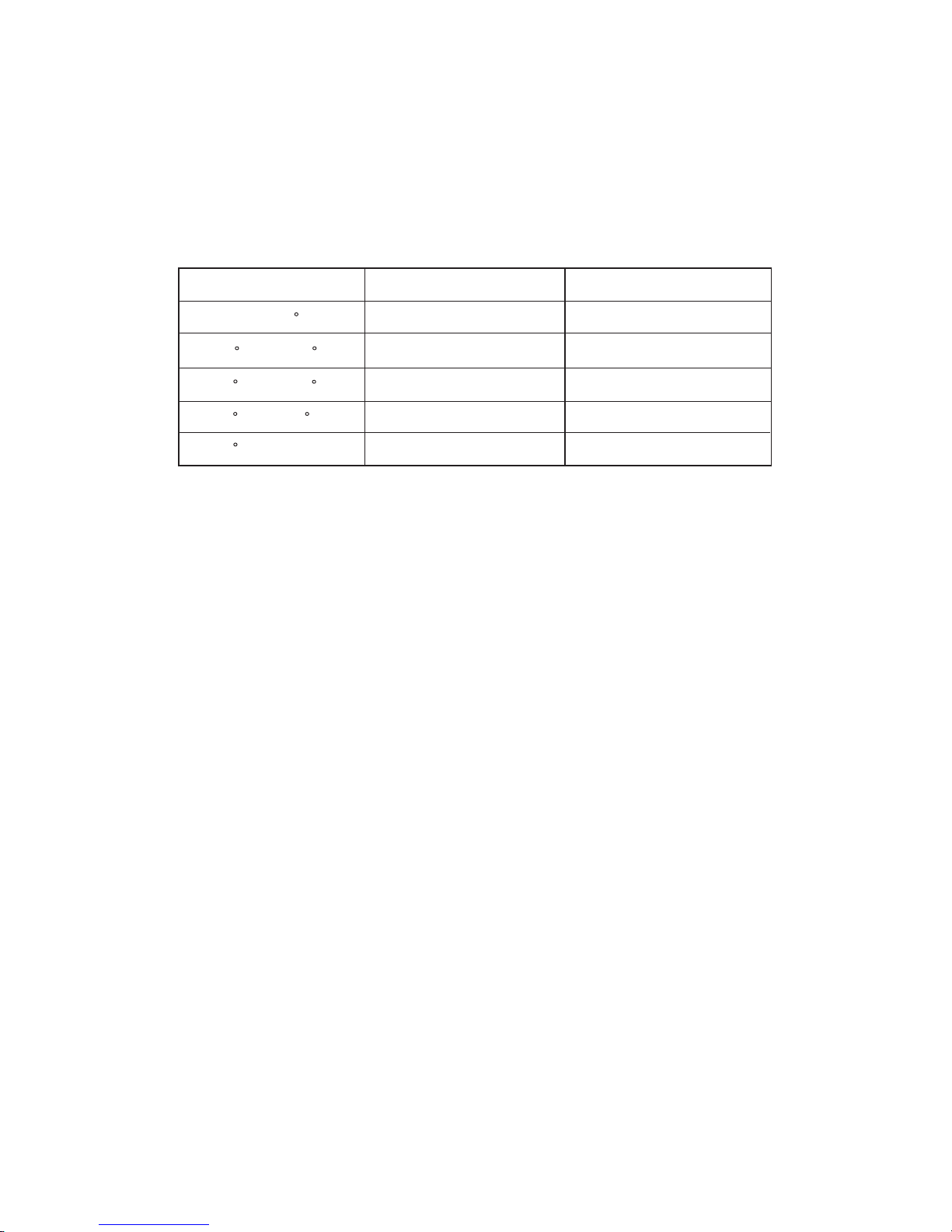
(b) Fan speed of heating mode and heating main mode
The fan 1 and fan 2 rotate in High-High speed.
(c)
Same capacity fan control
When the operating mode of the outdoor unit is the same capacity mode, the fan fan1 and fan2 are turned off.
When the operating mode of the outdoor
unit
is changed from the same capacity operating mode to another
operating mode, the fan operates in accordance with the new operating mode.
3 Fan Speed Switching
(a) Fan speed of cooling mode, cooling main mode and oil recovery operation
The fowllowing table shows the fan speed associated with outdoor temperature.
OUTDOOR TEMPERATURE
NORMAL OPERATING MODE
SILENT OPERATING MODE
Fan speed switched according to outdoor temperature
THO>
1
3
1
>
=
THO>
>
=
THO>
>
=
THo
(THO)
3
1
4
5
3
4
5
30
C
30
C
27
C
27
C
18
C
>
=
THO>
18
C
6
C
6
C
03-05
Page 54

Power source turned ON
Stand by
1) Purpose of the control
3-4 EXPANSION VALVES 1 AND 2 CONTROL
03-06
In order to balance the refrigerant flow rate of each heat exchanger and to adjust the refrigerant gas to an
optimum state, a feedback control of expansion valves 1 and 2 is performed by using operation date which
is obtained with thermistors and pressure sensors.
2) Operation flow chart of expansion valves
Initialization of
expansion valves
Does any of
the compressors
start to operate?
Automatic control
of expansion valves
Is any of the
compressors
operating?
Watching
Does any of
the compressors
start to operate?
Do expansion
valves need to be
initialized?
(Oil recovery or Defrosting
operation)
No
Yes
Yes
No
No
No
Yes
Yes
The expansion valves are initialized at intervals of 4 hours (about).
*
Expansion valves automatic
controlled
Page 55

03-07
(1) Compressor(s) is(are) operating, except for the case that only compressor 1 (2HP) is operating
.
(2) Operatring mode is "Cooling" or "Heating".
1) Expansion Valve 3 Control
As there is a difference between compressor’s actual capacity (operating capacity) and required
capacty (from indoor units), the difference in capacity is bypassed as a circulating save amonunt.
( Operating capacity – required capacity )
2) Start condition
3) End condition
(1) Only commpressor 1 (2HP) is operating.
(2) When the operating mode is switched to other than " Cooling" or "Heating".
3-5
CIRCULATING SAVE AMOUNT CONTROL
The solenoid valve 2 is controlled according to the difference between operatiog capacity and required
capacity during the same capacity operatration mode.
3-6 SOLENOID VALVE 2 CONTROL
When all the following conditions are satisfied.
When any of the following condition is satisfied.
Page 56

3-7 DEFROSTING CONTROL
03-08
1) Purpose of operation
By removing the frost that was formed on the surface of the outdoor unit heat eachanger, the defrosting operation
prevents a decline in heat transfer efficiency and realizes an efficient heating operation.
2) About the defrosting operation
(1) Starting condition of the defrosting operation
The defrosting operation starts when all the following conditions are satisfied.
Outdoor unit operation mode is "heating".
Integrated time which any of the compressors is operating has reached 40 minutes or longer.
(3) End condition of the defrosting operation
When any of the following conditions is satisfied, defrosting operation ends.
When compressor(s) starts to operation from "all compressors stopped" state, and has operated continuously for
more than 6 10 min.
Outdoor unit operation mode was switched to other than "Heating"
20 minutes or longer have elapsed since defrosting operation started.
The temperature of outlet of heat exchangers has become lower than the set temperature for starting a defrosting
operation. (See 2-3-2 for the information on defrost temperature setting.)
3) Others
During the defrosting operation the fans of indoor units stop,
appears on the display of wired and central
DEFROST
remote controller, and appears on the simple remote controller.
The operation indicators (LED) of the indoor units flash slowly.
The defrosting operation can also be performed by setting the forced defrost operation DIP SW 1- 4 from OFF to ON,
and keeping it at ON position for more than10 seconds. To stop the defrosting operation, set the DIP SW1- 4 to OFF.
(2) Defrosting start restrictions
When oil recovery operation is in progress or errors or protections (except for some) were generated, Defrosting
operation will not be performed even if the conditions mentioned above are satisfied.
Integration of compressor operation time after start of defrosting has exceeded 15 minutes.
The error was generated, except for some error conditions.
Each heat exchanger outlet temperature has reached defrosting end heat exchanger temperature 10 or higher.
Page 57

2. Oil return solenoid valves
Individual oil return
Central oil return control
Solenoid valve Application
Solenoid valve SV3
SV4
SV5
SV6
Compressor 1
Compressor 2
Compressor 3
Compressor 1/2/3
3. Individual oil return control
When a compressor operates continuously for 1 minute or longer and any of the following conditions is satisfied,
the solenoid valve corresponding to the compressor opens for 10 seconds to return the oil accumulated in the
oil separator to the compressor.
(1) The integrated operating time of the compressor has reached 15 minutes or longer.
(2) The compressor is stopped.
4. Central oil return control
When any of the following conditions is satisfied, the solenoid valve SV6 opens on and central oil return control
begins.
(1) One or more compressors are operating and the integrated time of "1 or more compressors operating" state
exceeds 15 minutes
(2) All the compressors are stopped.
3-8 OIL RETURN CONTROL
OIL
SEPARATOR
OIL
SEPARA
OIL
SEPARA
COMP.1
COMP.2
COMP.3
SV3
SV4
SV5
SV6
There are two oil return controls, one is the individual oil return control
and the other one is centralized oil return control. When any of the
solenoid valves opens, the oil return is performed.
TOR
TOR
control
03-09
1. Two kinds of oil return control
Page 58
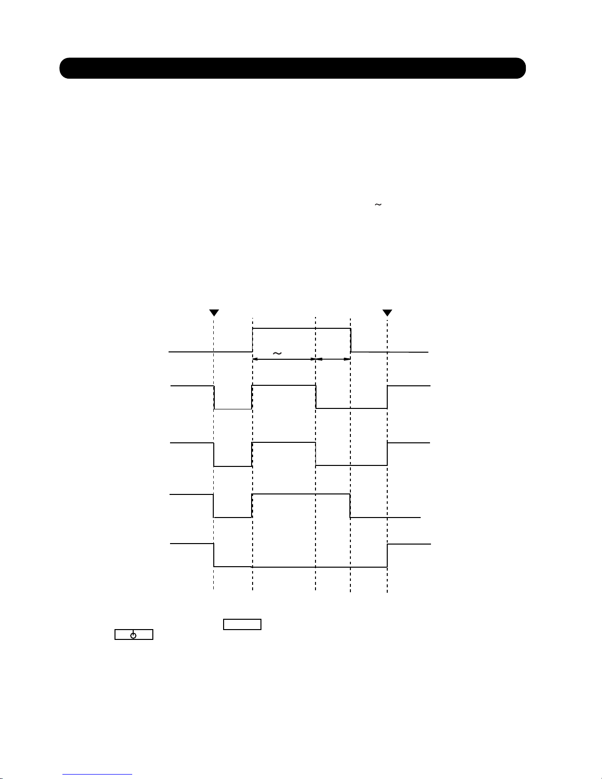
Compressor 1
ON
OFF
Indoor Fan
3-9 OIL RECOVERY CONTROL
OFF
OFF
OFF
ON
ON
ON
Compressor 2
Compressor 3
4 9mins
1 min
Oil recovery start
Oil recovery end
03-10
Outdoor Fan
OFF
ON
1) Purpose of the operation
The amount of refrigerant machinery oil which has been transported to the indoor units and the connection pipe with the
refrigerant will become large as the operation time of compressor increase. It is necessary to recover the oil back into
the outdoor unit for a certain time interval in order to prevent compressors from damaging due to lack of lubrication oil.
2) About the oil recovery operation
When "oil recovery integrated time", which is the integrated operating time of any compressor in operation,
reaches to the certain time, the oil recovery operation starts.
The "oil recovery integrated time" to start the oil recovery is as follows.
- The first time of oil recovery after the power is turned on : 1 hour
- The second time and afterwards : At intervals of 4 6 hours
Please note that "oil recovery integrated time" is reset to zero at the end of defrosting operation.
The oil recovery operation can be performed by setting the forced oil recovery DIP SW2-4 from OFF to ON and keeping
it at ON position for more than 10 seconds.
3) The operation of compressors and fans
The following time chart shows the behavior of compressors, outdoor fan and indoor fan during oil recovery operation.
DEFROST
4) Others
During the oil recovery operation, appears on the display of wired and central remote controller,
and appears on the simple remote controller.
The operation indicators (LED) of the indoor units flash slowly.
Page 59

1. Central discharge temperature protection
1) When the discharge temperature of any compressor reaches 110 C or higher, solenoid valve 1 (SV1)
is turned on and bypass is performed. SV1 is turned off and central discharge temperature protection
operation is ended by any of the following conditions:
(1) Discharge temperature of all compressors reaches 95 C or lower.
(2) Oil recovery operation starts.
2) When solenoid valve 1 (SV1) is on and the outdoor fan speed is "5"(about fan speed, please refer to 3-3),
solenoid valve 2 (SV2) is simultaneously turned on and bypass is performed. SV2 is turned off by any of
the following conditions:
(1) Outdoor fan speed is set to other than "5".
(2) Oil recovery operation starts.
(3) Discharge temperature of all compressors reaches 95 C or lower.
2. Discharge temperature protection
3. High-pressure protection
1) When the high-pressure SW (HP) is turned off except during oil recovery operation or defrosting,
solenoid 1 (SV1) and solenoid 2 (SV2) are turned on and bypass is performed. SV1 and SV2 are turned
off by any of the following conditions:
(1) High-pressure pressure SW turned on.
(2) Oil recovery control starts.
(3) Defrosting control starts.
2) When 1 minute has elapsed after SV1 and SV2 were turned on and the discharge pressure sensor
detected value is 3.34MPa or higher, compressors 1, 2, and 3 are stopped. SV1 and SV2 ON and
compressors 1, 2, and 3 stop are reset and high-pressure protection operation is ended by any of the
following conditions:
(1) High-pressure SW turned on.
(2) Oil recovery control starts.
(3) Defrosting control starts.
4. Heating overload protection
When the operating mode is " Heating " and the high-pressure SW was turned off except during oil recovery or
defrosting in the "Heat mode", the outdoor fan is stopped. Outdoor fan stop is reset and heat overload protection
operation is ended by any of the following conditions:
(1) High-pressure SW turned on.
(2) Oil recovery control starts.
(3) Defrosting control starts.
(4) Mode is switched to other than "Heat".
When the discharge temperature of any compressor reaches 130 C or higher, the corresponding compressor
stops. Compressor stop is reset and discharge temperature protection operation is ended by any of the following
conditions:
(1) Discharge temperature of all compressors reaches 95 C or lower.
(2) Oil recovery operation starts.
However, during oil recovery operation, discharge temperature protection is not performed.
3-10 PROTECTION FUNCTIONS
03-11
Page 60

4 . INDOOR UNIT OPERATION
TM
R407C
Page 61

4-1 TIMER CONTROL
There are three timer modes: "OFF TIMER", "ON TIMER" and
"WEEKLY TIMER" .
(1) Set the clock time when the unit is in the stop mode (only the
current time will be shown on the remote control unit display).
(2) While adjusting the current clock time, do not use other
remote control functions.
(3) Each time the TIMER button is pressed, the remote control
unit display will change in the order shown below:
Remote control button selected
OFF timer setting
1) OFF timer
When the timer mode is set to "OFF timer", operation automatically
stops when the set time has elapsed.
NON STOP
OFF
WEEKLY
ON
2) ON timer
When the timer mode is set to "ON TIMER" , operation automati-
cally starts when the set time has elapsed.
ON timer setting
3) WEEKLY timer
Use the weekly timer to set operating times for each day of the
week.
Weekly Timer Features
Set different operating times for each day of the week.
Set one or two operating spans (one or two ON times and one
or two OFF times) per day.
Set time to a resolution of 5 minutes.
OFF time can be carried over to the subsequent day.
Use the "DAY OFF" setting to cancel operation for any day of
the coming week (one-time cancellation).
ON
SET
MASTER
CONTROL
FAN
CONTROL
TIMER
MODE
TEMP./DAY
SET TIME
CLOCK ADJUST
START/STOP
SET
DAY OFF
ZONE
ENERGY SAVE
COOL
CLOCK
OFF
C
TIMER
OFF
TIMER
4. INDOOR UNIT OPERATION
OFF
SET
04-01
1
2
Page 62
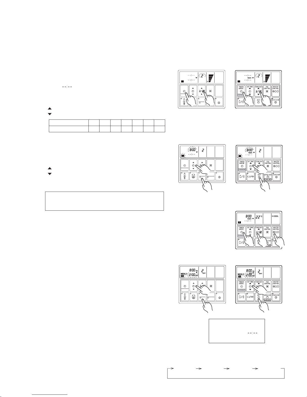
Setting Up the Weekly Timer Operation
Press the START/STOP button to stop the air conditioner, and
then proceed as follows.
1. Press the TIMER MODE button so that "WEEKLY"
appears on the display.
The display now shows the current day (by DAY CODE), the
first ON and OFF times for the day (the "WEEKLY 1" times),
the fan speed, and the operating mode.
The top time value gives the ON time, and the bottom value
gives the OFF time.
If either time is not set, the corresponding time display is
blank " ".
2. Press the TEMP./DAY button to select the day that
you want to set up.
: Use to advance the day forward.
: Use to turn the day back.
3. Hold the SET button down for 3 seconds.
The "WEEKLY 1" ON time starts flashing, and the fan speed
and operating mode displays go off.
4. Press the SET TIME button to set the day's first ON time.
: Use to advance the day forward.
: Use to turn the day back.
(Press once to move the time 5 minutes; hold down and the
time will move 10 minutes at a time.)
8. Press the SET button.
This registers the first ON time setting for the selected day.
The ON time display stops flashing, and the "WEEKLY 1"
OFF time starts flashing.
9. Press the SET TIME button to set the day's first OFF time.
The earliest OFF time you can set is 5 minutes after the ON
time. The latest OFF time is 23:55 on the subsequent day.
10. Press the SET button.
This registers the first OFF time for the day, completing the
"WEEKLY 1" settings for that day.
The display switches to "WEEKLY 2", and the day's second
ON time begins flashing.
11. Repeat the operations described in Steps 4 to 10 to set
the second ON and OFF times for the day (the "WEEKLY 2" times).
When you press the SET button after setting the "WEEKLY 2"
OFF time, the system registers the "WEEKLY 2" settings for
the day and returns you to the "WEEKLY 1" ON time setup
process. (The first ON setting reappears and begins flashing.)
You can review your settings by pressing the SET button.
Each press moves you to the next setting, as follows.
DAY CODE
DAY OF THE WEEK
1
MON2TUE3WED4THU5FRI6SAT7SUN
If the timer is not set, press
the SET button with the
time display blank " ",
and perform next operation.
WEEKLY 1ONWEEKLY 1
OFF
WEEKLY 2ONWEEKLY 2
OFF
04-02
MASTER
CONTROL
FAN
CONTROL
TIMER
MODE
TEMP./DAY
SET TIME
CLOCK ADJUST
START/STOP
SET
DAY OFF
ZONE
ENERGY SAVE
COOL
OFF
ON
DAY
TIMER
WEEKLY
1 2
MASTER
CONTROL
FAN
CONTROL
TIMER
MODE
TEMP./DAY
SET TIME
CLOCK ADJUST
START/STOP
SET
DAY OFF
ZONE
ENERGY SAVE
1
2
9
8,
10
UTB - LB
*
COOL
OFF
ON
DAY
WEEKLY
1 2
1
2
MASTER
CONTROL
FAN
CONTROL
TIMER
MODE
TEMP./DAY
SET TIME
CLOCK ADJUST
START/STOP
SET
DAY OFF
ZONE
ENERGY SAVE
OFF
ON
DAY
TIMER
WEEKLY
1
4
3
3
OFF
ON
DAY
WEEKLY
1
4
5, 7
6
6
OFF
ON
WEEKLY
8,
10
9
UTB - LA
*
5. Press the TIMER MODE button.
The day display changes to the set temperature display.
6. Press the MASTER CONTROL and the TEMP./DAY button.
Select the desired operation mode and temperature.
7. Press the TIMER MODE button.
End operation mode and temperature setting.
The following procedures of 5, 6, 7 is for UTB- LB type
wired remote controller. Goto 8 directly when UTB- LA
is used.
*
*
TIMER
Page 63
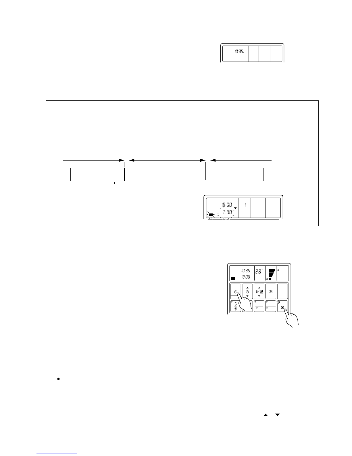
NOTES:
(1) If no time values are flashing, the clock display will automatically reappear after 15 seconds if no buttons are pressed.
(2) A flashing time value indicates that the system is in time-setting mode. To return to the clock display you
must hold down the SET button for 3 seconds.
(3) You do not need to set values for both WEEKLY 1 and WEEKLY 2. If you wish, you can set values only for
WEEKLY 1 or only for WEEKLY 2.
(4) The allowable range for the day as time settings is shown below.
(5) If you set the OFF time to occur on the day following the ON
time, the NEXT DAY caption appears on the display.
Next day’s WEEKLY
settings
Cannot set
5 min.
Available range Cannot set
5 min.
ON OFF ON OFF
Previous day’s WEEKLY
settings
0:00 0:00
TIMER
NEXT DAY
DAY
WEEKLY
ON
OFF
21
Starting Weekly Timer Operation
1. Press the TIMER MODE button so that "WEEKLY"
appears on the display.
2. Press the START/STOP button to start operation.
(This step is not necessary if the air conditioner is already
running.)
Weekly timer operation starts, and the operation lamp comes on.
(If the current time is between the first or second ON and OFF
time settings for the current day, the air conditioner will start.
Otherwise the air conditioner will remain off.)
The day display is replaced by the temperature display.
The upper time display now shows the current time, and the
lower time display shows the next scheduled ON or OFF time.
To Stop Weekly Timer Operation
To stop weekly timer while leaving the air conditioner
running:
Press the TIMER MODE button to select NONSTOP,
OFF TIMER, or ON TIMER.
To stop weekly timer operation and the air conditioner
also:
Press the START/STOP button.
Reviewing the Time Settings
Press the START/STOP button to stop the air conditioner, and then proceed as follows.
1 Press the TIMER MODE button so that "WEEKLY"
appears on the display.
2 Press the TEMP./DAY button to select the day
that you want check.
3 Press the SET TIME button ( or ) to switch
between the "WEEKLY 1" or "WEEKLY 2" time displays.
12. Press the SET TEMP./DAY button to select another day
for setup. The repeat steps 4 to 10 above to set the ON and
OFF times for that day.
13. When you have finished setting all of the times, hold
down the SET button for 3 seconds.
The WEEKLY display flashes for 3 seconds while the new
WEEKLY TIMER settings are registered, and then the clock
display reappears.
CLOCK
MASTER
CONTROL
FAN
CONTROL
TIMER
MODE
TEMP./DAY
SET TIME
CLOCK ADJUST
START/STOP
SET
DAY OFF
ZONE
ENERGY SAVE
COOL
CLOCK
OFF
C
DAY
TIMER
WEEKLY
1
04-03
1
2
Page 64

NOTES:
(1) The DAY OFF setting is only available for days for which weekly time settings already exist.
(2) You can make this setting for any of the next seven days (counting from the current day).
(3) The DAY OFF setting is effective over the range illustrated below. The weekly setting for which an ON time
has been set is eligible for the day in which the DAY OFF has been set.
(4) The display on the clock's lower line will usually be " " for the DAY OFF set day during weekly operations
Next day
ON OFF
0:00 0:00
Effective range of DAY OFF setting
WEEKLY setting for preceding
day
WEEKLY setting
Preceding day DAY OFF day
ON
OFF
About the DAY OFF setting
Use the DAY OFF setting to switch off timed operation for a selected day in the coming week.
This is a temporary, one-time setting. The DAY OFF setting is automatically cleared as soon as the specified day passes.
Precautions during setup
Setup is not possible in the following cases, so amend the time.
If you set an ON time while leaving the OFF time setting blank:
Nothing will happen when you press the SET button.
To proceed, press the SET TIME button and enter an appropriate setting.
When an attempt is made to set only the OFF time.
Nothing will happen when you press the SET TIME button.
Press the SET button and amend the entry for the ON time.
ON and OFF times cannot be set to the same value.
The OFF time cannot be set earlier than the ON time.
The WEEKLY 2 settings cannot be set earlier than the WEEKLY 1 settings.
The WEEKLY 1 and WEEKLY 2 time spans cannot overlap.
Using the DAY OFF Setting
Press the START/STOP button to stop the air conditioner, and
then proceed as follows.
1. Carry out steps 1 to 2 of the "Setting Up the Weekly
Timer Operation" procedure to select the day that you
want to set as the DAY OFF.
2. Press the DAY OFF button.
The DAY OFF setting is registered, and the DAY OFF caption
appears on the display.
To cancel the DAY OFF setting:
You can cancel the setting by pressing the DAY OFF button
again.
Example : To switch off timed operation for day 2
(Tuesday).
MASTER
CONTROL
FAN
CONTROL
TIMER
MODE
TEMP./DAY
SET TIME
CLOCK ADJUST
START/STOP
SET
DAY OFF
ZONE
ENERGY SAVE
CLOCK
OFF
ON
DAY
TIMER
WEEKLY
DAY OFF
1
COOL
CLOCK
C
TIMER
WEEKLY
DAY OFF
COOL
04-04
2
Page 65

Cancelling Selected Time Settings
Press the START/STOP button to stop the air conditioner, and
then proceed as follows.
1. Carry out steps 1 to 3 of the "Setting Up the Weekly TImer
Operation" procedure to select the day you want to edit.
2.
Press the SET button to select the ON time that you want to cancel.
To Change Selected Time Settings
Press the START/STOP button to stop the air conditioner, and
then proceed as follows.
1. Carry out steps 1 to 3 of the "Setting Up the Weekly Timer
Operation" procedure to select the day you want to edit.
2.
Press the SET button to select the time that you want to change.
The selected setting flashes on the display. Each press
moves you to the next setting for the selected day, as follows.
3. Hold down the side of the SET TIME button until the
time display becomes blank " ".
4. Press the SET button.
The first OFF time setting ("WEEKLY 1" OFF time) is deleted
and replaced by a flashing blank pattern " ".
5. Press the SET button again.
This completes deletion of the "WEEKLY 1" ON/OFF settings.
The second ON time setting ("WEEKLY 2" ON time) appears
and flashes.
If you wish to delete other time settings, repeat steps 2
through 5.
6. Once the setting has been canceled, hold down the SET
button for 3 seconds.
The WEEKLY display flashes briefly, and then the clock display appears.
TIMER
DAY
WEEKLY
AUTO
ON
OFF
TIMER
MODE
START/STOP
CLOCK ADJUST
SET TIME TEMP./DAY FAN
CONTROL
MASTER
CONTROL
21
AUTO
DEFROST TEST
SET
DAY OFF
2
3
TIMER
DAY
WEEKLY
AUTO
ON
OFF
21
AUTO
DEFROST TEST
TIMER
DAY
WEEKLY
AUTO
ON
OFF
21
AUTO
DEFROST TEST
Be sure to select an ON time (the upper time display).
Example : Clearing the "WEEKLY 1" ON/OFF
times for day 4 (Thursday).
Example : Changing the "WEEKLY 2" ON setting
for day 5 (Friday) from 14:00 to 15:30.
WEEKLY 1ONWEEKLY 1
OFF
WEEKLY 2ONWEEKLY 2
OFF
NOTES:
In the following cases, cancel the set time prior to making the required amendments.
(1) If you want to change the ON time to a time that is later than the currently set OFF time.
(2)
If the change would cause a temporary overlap between the first and second ON/OFF time spans.
ON OFF
WEEKLY 1
ON OFF
WEEKLY 1
Change
Time
Time
Temporary overlap
Change
Time
Time
ON OFF
WEEKLY 1
ON OFF
WEEKLY 2
OFF ONON OFF
WEEKLY 1 WEEKLY 2
3. Press the SET TIME button to change the time setting.
4. Press the SET button.
The new setting overwrites the previous setting.
5. Once the setting has been canceled, hold down the SET
button for 3 seconds.
The WEEKLY display flashes briefly, and then the clock display appears.
MASTER
CONTROL
FAN
CONTROL
TIMER
MODE
TEMP./DAY
SET TIME
CLOCK ADJUST
START/STOP
SET
DAY OFF
ZONE
ENERGY SAVE
OFF
ON
DAY
TIMER
WEEKLY
1
MASTER
CONTROL
FAN
CONTROL
TIMER
MODE
TEMP./DAY
SET TIME
CLOCK ADJUST
START/STOP
SET
DAY OFF
ZONE
ENERGY SAVE
OFF
ON
DAY
TIMER
WEEKLY
2
MASTER
CONTROL
FAN
CONTROL
TIMER
MODE
TEMP./DAY
SET TIME
CLOCK ADJUST
START/STOP
SET
DAY OFF
ZONE
ENERGY SAVE
OFF
ON
DAY
TIMER
WEEKLY
2
04-05
2
3
2
4
3
Page 66

Fan speed zone
Hi zone
Med zone
Low zone
When the room
temperature decreases
When the room
temperature increases
2) HEATING OPERATION
3) DRY OPERATION
An example for heat operation
Indoor heat
exchanger
temperature (THE )
Indoor fan speed
mode
47
41
HI
MED
LOW
OFF
(2)
(1)
(3)
TIME -->
2min.
2min.
2min.
2min.
THE
The indoor fan operates at the fan speed set with the FAN CONTROL mode button.
4) FAN OPERATION
The indoor fan rotates continuously at "Lo" speed.
1) COOLING OPERATION
• Expansion
• valve
• Indoor fan
motor
ON
OFF
OPEN
CLOSE
ON
ON
ON
ON ON ON
ON
ON
30s
30s
5s
3min
5s
3min
The indoor fan always rotates at "Lo" speed.
TIME -->
MASTER
CONTROL
FAN
CONTROL
TIMER
MODE
TEMP./DAY
SET TIME
CLOCK ADJUST
START/STOP
SET
DAY OFF
ZONE
ENERGY SAVE
AUTO
CLOCK
C
NON STOP
•
•
04-06
2
TR-TS
1
2
TR-TS
1
TR-TS
2
TR-TS
2
3
TR-TS
3
TR-TS
(1) When the TS is changed.
(2) When the operation mode is changed from other mode to "COOL".
(3) When the fan control is changed from other position to "AUTO".
The fan speed is determined automatically in accordance
with the condition "(TR(corrected room temperature) - TS
(corrected set temperature)" as shown on the right.
However, the fan speed zone is determined in the manner
as the room temperature increases for the following cases.
2min.
(1) The indoor fan starts operation 5 seconds after the electric expansion valve opens. However, when the indoor unit just starts
its operation or the operation mode is changed from other to "DRY" and the refrigerant circulation is not stopped, the fan will
rotate immediately without a delay time of 5 seconds.
(2) The indoor fan will stop in 30 seconds when the refrigerant circulation stops.
(3) The indoor fan will stop immediately when the indoor unit is stopped by pushing the stop button or by a setting of ON timer.
(4) When the refrigerant circulation is stopped due to a lower room temperature for more then 3 minutes, the fan will rotate
2 minutes at intervals of 3 minutes.
(5) When the indoor unit just starts its operation or the operation mode is changed from other to "DRY" and the refrigerant
circulation is stopped, the fan will rotate for 1 minute and then it will operate according to the statement (4).
2min
(1) When the indoor heat exchanger temperature reaches 47 or more, the fan speed switches to the next higher position.
("LOW" --> "MED", "MED" --> "HIGH").
(2) When the indoor heat exchanger temperature drops below 41 while the refrigerant circulation of the indoor unit is ON,
the fan speed switches to the next lower position ("HIGH" --> "MED", "MED" --> "LOW").
(3) After switching the fan speed, it does not switch again within 2 minutes.
(4) When "FAN CONTROL" is switched from a set fan speed to "AUTO" after the cold air prevention is released , the fan of
indoor unit will start at "MED" speed for THE or at "LOW" speed for THE .
41
41
4-2 FAN CONTROL
4-2-1 "AUTO" POSITION
4-2-2 "LOW", "MED" AND "HIGH" POSITION
Page 67

Indoor fan motor
Operates according to
the AIR FLOW-MODE
setting, and besides
Operates according
to the AIR FLOW-
MODE setting.
Operates according to the
AIR FLOW-MODE setting,
and besides
Cold air prevention
Defrost operation
See the fan control
page.
Cool Fan Heat Dry
Drain pump
Turns ON-OFF by the drain pump control function
Electrical
expansion valve
Pulse controlled by
the temperature differ-
ence calculation and
frost prevent fuction
Stop pulse
Pulse controlled by the
temperature difference
caculation and the
defrosting function
Each operating mode is controlled as below.
4-3-1 OPERATING MODE CONTROL
4-3 MASTER CONTROL
frost prevention
operation
Pulse controlled by
the temperature difference calculation
and frost prevent
function
RB
Unit
Discharge valve
(SVD)
Suction valve
(SVS)
By-pass
valve
SVB1
SVB2
Open
Open
Open
Close
Close
Open
Open
Close
Close
Open
Close
Stop pulse
Stop
Off
Schematics of the RB units
UTF-Y90A4A
Indoor
unit 1
Indoor
unit 2
Indoor
unit 3
Indoor
unit4
Gas
pipe
Liquid
pipe
Suction pipe
Discharge pipe
Liquid pipe
SV
S
SV
B2
SV
S
SV
S
SV
S
SV
D
SV
D
SV
D
SV
D
SV
B1
SV
B1
SV
B1
SV
B1
SV
B2
SV
B2
SV
B2
Gas
pipe
Gas
pipe
Gas
pipe
Liquid
pipe
Liquid
pipe
Liquid
pipe
To indoor unit
Gas
pipe
Suction
pipe
Discharge
pipe
SV
S
SV
B2
SV
D
SV
B1
UTF-Y54A1A
: Strainer
: Solenoid valve
: Capillary tube
04-07
Close
Open
Open
Close
Close
Close
Close
Close
Close
Page 68

(1) When AUTO CHANGEOVER is selected, the air conditioner selects the appropriate operating mode (Cooling or Heating)
according to your room's present temperature.
(2) When AUTO CHANGEOVER is first selected, the fan will operate at very low speed for about one minute while the unit
determines the current conditions of the room and accordingly selects the proper operating mode.
(3) When the air conditioner has adjusted your room
's temperature to near the set temperature, it will begin monitor operation. In the monitor operating mode, the fan will operate at low speed. If the room temperature subsequently changes, the
air conditioner will once again select the appropriat
e operation (Heating, Cooling) to adjust the temperature to the set temperature.
(4) If the mode automatically selected by the unit is not satisfactor, you can change the operating mode by press the MASTER
CONTROL button to select the desired mode.
AUTO COOL
DRY
FAN HEAT
4-3-2 "AUTO" (Auto changeover) POSITION
During operation
or
Start of operation
Operating mode : AUTO
is selected
Detecting the room
temperature (TR)
TR
<
=
TS-2DEG.
TR
>
=
TS+2DEG.
Heating operation
Refrigerant
Circulating stopped?
(due to temp.)
Refrigerant
Circulating stopped?
for more than
Is
6min.
Cooling operation
Refrigerant
Circulating stopped?
(due to temp.)
Refrigerant
Circulating stopped?
for more than
Is
6min.
NO
NO
YES
YES
YES
YES
YES
YES
NO
NONO
NO
TS: Corrected setting temperatured
TR: Corrected room temperatured
04-08
Page 69

4-3-5 "FAN" POSITION
(1) In this position, the fan merely rotates to circulate air, so the room temperature will not change.
(2) The fan will rotate at a fan speed set with the FAN CONTROL button.
(3) When only the “FAN” mode is being used, setting the fan speed at “AUTO” is equivalent to setting it at “Low”.
04-09
An example for COOLING TEMPERATURE CONTROL time chart (Manual setting)
When using the cooling mode, set the temperature to a value lower than the current room temperature, otherwise
the indoor unit will not start the cooling operation and only the fan will rotate.
4-3-3 "COOL" POSITION
4-3-4 "HEAT" POSITION
(1) When using the heating mode, set the temperature to a value higher than the current room temperature, otherwise
the indoor unit will not start the heating operation.
(3)
An example for HEATING TEMPERATURE CONTROL time chart (Manual setting)
During defrosting, the OPERATION indicator lamp flashes 3 sec. ON and 1 sec. OFF, and repeat. The heating operation
will be temporarily interrupted.
• Indoor fan
Ts
• Opening of
EEV
100%
0%
• Refrigerant
flow
ON
OFF
ON
OFF
• Temperature
Ts + T1
Ts - T2
TR
3Min.
Ts : Corrected setting temperature
TR : Corrected room temperature
• Indoor fan
Ts
• Opening of
EEV
100%
0%
• Refrigerant
flow
ON
OFF
ON
OFF
• Temperature
Ts + T3
Ts - T4
TR
4Min.
1Min.
4Min.
1Min.
4Min.
1Min.
Ts +T1 : The thrshold temperature of start of refrigrant flow
TR - T2 : The thrshold temperature of stop of refrigrant flow
Ts : Corrected setting temperature
TR : Corrected room temperature
Ts +T3 : The thrshold temperature of start of refrigrant flow
TR - T4 : The thrshold temperature of stop of refrigrant flow
: Duration of cold air prevention
(2) After the start of heating operation, the fan of indoor unit will not rotate until the heater exchange is warmed up to
blow out warm air.
Page 70

Instructions relating to heating ( ) are applicable only to heat pump type
outdoor unit.
Begin air conditioner operation before performing this procedure.
Vertical Air Direction Adjustment
This instructions are applicable to "LARGE CEILING TYPE",
"UNIVERSAL FLOOR/CEILING TYPE", "CASSETTE TYPE",
"WALL MOUNTED TYPE","COMPACT WALL MOUNTED TYPE"
and "CEILING WALL TYPE".
Press the VERTICAL AIR FLOW DIRECTION SET button.
Each time the button is pressed, the air direction will change as
follows, expept for compact wall mounted type indoor units operating
under cooling mode.
LARGE CEILING TYPE
The remote controller's display does not change.
UNIVERSAL FLOOR/CEILING TYPE
CASSETTE TYPE
Example : When set to vertical air direction.
DANGER!
(1) ADJUSTING THE DIRECTION OF AIR CIRCULATION
MASTER
CONTROL
FAN
CONTROL
TIMER
MODE
TEMP./DAY
SET TIME
CLOCK ADJUST
START/STOP
SET
DAY OFF
ZONE
ENERGY SAVE
WALL MOUNTED TYPE
1 2 3 4
1
2
3
4
1
2
3
4
1
2
3
4
3
4
04-10
2
1
Never place fingers or foreign objects inside the
outlet ports, since the internal fan opertes at
high speed and could cause personal injury.
Always use the remote control umit's
AIR FLOW DIRECTION button to adjust
the UP/DOWN air direction flaps or
RIGHT/LEFT air direction louvers. Attempting to move them manually
could result in improper operation; in
this case, stop operation and restart.
The louvers should begin to operate
properly again.
During use of the Cooling and Dry
modes, do not set the UP/DOWN air
direction flaps in the position of
(Compact wall mounted type &
long periods of time, since water vapor
may condense near the outlet port and
drops of water may drip from the air
conditioner.
When used in a room with infants, children, elderly or sick persons, the air
direction and room temperature
should be considered carefully when
making settings.
4
CEILING WALL TYPE
For compact wall mounted type indoor units operating under
cooling mode.
1 2
4
3
for
COMPACT WALL MOUNTED TYPE
Cooling &
Heating
Heating
4-4 LOUVER CONTROL
1
2
3
4
1
2
3
4
Page 71

Horizontal Air Direction Adjustment
This instructions are applicable to "LARGE CEILING TYPE",
"UNIVERSAL FLOOR/CEILING TYPE", "WALL MOUNTED TYPE"
and "CEILING WALL TYPE".
Press the HORIZONTAL AIR FLOW DIRECTION SET button.
Each time the button is pressed, the air direction range will
change as follows:
The remote controller's display does not change.
LARGE CEILING TYPE
UNIVERSAL FLOOR/CEILING TYPE
WALL MOUNTED TYPE
Example : When set to horizontal air direction.
Use the air direction adjustments within the ranges shown above.
The vertical airflow direction is set automatically as shown, in accordance with the type of operation selected.
During Cooling mode : Horizontal flow
During Heating mode : Downward flow
During AUTO mode operation, for the first minute after beginning operation, airflow will be horizontal ,
the air direction cannot be adjusted during this period.
MASTER
CONTROL
FAN
CONTROL
TIMER
MODE
TEMP./DAY
SET TIME
CLOCK ADJUST
START/STOP
SET
DAY OFF
ZONE
ENERGY SAVE
(2) SWING OPERATION
Instructions relating to "the indoor unit's indicator lamp" ( ) are applicable to "LARGE CEILING TYPE", "UNIVERSAL
FLOOR / CEILING TYPE", "CASSETTE TYPE", "WALL MOUNTED TYPE","COMPACT WALL MOUNTED TYPE" and
"CEILING WALL TYPE".
Begin air conditioner operation before performing this procedure.
To select Vertical airflow SWING Operation
This instructions are applicable to "LARGE CEILING TYPE", "UNIVERSAL FLOOR/CEILING TYPE",
"CASSETTE TYPE", "WALL MOUNTED TYPE", "COMPACT WALL MOUNTED TYPE" and "CEILING WALL TYPE".
1
4
1
1 2 3 4 5
1
3
4
5
2
04-11
1
2
3
4
5
1
2
3
4
5
CEILING WALL TYPE
Press the VERTICAL SWING button for more than two seconds.
The remote controller's VERTICAL SWING lamp (orange) **and
indoor unit's SWING indicator lamp (VERTICAL SWING)
(orange) will light up.
In this mode, the UP/DOWN air direction flaps will swing automatically to direct the air flow both up and down.
Example : When set to vertical swing.
MASTER
CONTROL
FAN
CONTROL
TIMER
MODE
TEMP./DAY
SET TIME
CLOCK ADJUST
START/STOP
SET
DAY OFF
ZONE
ENERGY SAVE
Page 72

Instructions relating to "the indoor unit's indicator lamp" (**) are
applicable to "LARGE CEILING TYPE", "UNIVERSAL FLOOR /
CEILING TYPE", "CASSETTE TYPE", "WALL MOUNTED TYPE",
"COMPACT WALL MOUNTED TYPE" and "CEILING WALL TYPE".
About Vertical Airflow SWING Operation
The range of swing is relative to the currently set airflow direction.
If the swing range is not as desired, use the remote controller's
VERTICAL AIR FLOW DIRECTION SET button to change the
range of swing.
The SWING operation may stop temporarily when the air conditioner's fan is not operating, or when operating at very low
speeds.
About Horizontal Airflow Swing Operation
The range of swing is relative to the currently set airflow direc
tion.
If the swing range is not as desired, use the remote controller's
HORIZONTAL AIR FLOW DIRECTION SET button to change
the range of swing.
The SWING operation may stop temporarily when the air conditioner's fan is not operating, or when operating at very low speed.
Air flow direction set
Range of swing
to
to
to
to (All range)
Air swing range (Expect for compact wall mounted type indoor unit)
Air direction range
To select Horizontal Airflow SWING Operation
This instructions are applicable to "LARGE CEILING TYPE",
"UNIVERSAL FLOOR / CEILING TYPE", "WALL MOUNTED TYPE"
and "CEILING WALL TYPE".
Press the HORIZONTAL SWING button for more than two seconds.
The remote controller's HORIZONTAL SWING lamp (orange)
**and indoor unit's SWING indicator lamp (HORIZONTAL
SWING) (orange) will light up.
In this mode, the RIGHT/LEFT air direction louvers will swing
automatically to direct the airflow both right and left.
To stop Horizontal airflow SWING Operation
Press the HORIZONTAL SWING button for more than two seconds
once and again.
The remote controller's HORIZONTAL SWING lamp **and indoor
unit's SWING indicator lamp (HORIZONTAL SWING) will go out.
Airflow direction will return to the setting before swing was begun.
Example : When set to horizontal swing.
To Stop Vertical airflow SWING Operation
Press the VERTICAL SWING button for more than two seconds
once and again.
The remote controller's VERTICAL SWING lamp **and indoor
unit's SWING indicator lamp (VERTICAL SWING) will go out.
Airflow direction will return to the setting before swing was begun.
MASTER
CONTROL
FAN
CONTROL
TIMER
MODE
TEMP./DAY
SET TIME
CLOCK ADJUST
START/STOP
SET
DAY OFF
ZONE
ENERGY SAVE
Air flow direction set
Range of swing
to (All range)
to
to
to
to (All range)
1
2
3
4
1
2
2
3
4
4
1 4
1
1
2
3
1 5
3
4
5
5
5
4
3
2
1
04-12
Air flow direction set
Range of swing
to
to
1
2
3
4
1
2
3
4
Air swing range (Compact wall mounted type indoor unit)
or
or
Air swing range
Page 73

04-13
4-5 ENERGY SAVE OPERATION
MASTER
CONTROL
FAN
CONTROL
TIMER
MODE
TEMP./DAY
SET TIME
CLOCK ADJUST
START/STOP
SET
DAY OFF
ZONE
ENERGY SAVE
COOL
FAN
DRY
HEAT
AUTOAUTO
CLOCK
OFF
OFF
ON
ON
C
F
NEXT DAY
DAY
TIMER
NON STOP
OFFON
TIMER
WEEKLY
ANTI FREEZE
CENTRAL
DAY OFF
DEFROST
TEST
12
(3) To Stop the ENERGY SAVE
Press the ENERGY SAVE button one more time.
The ENERGY SAVE mode will be turned off.
The ENERGY SAVE light goes off, and the unit will return to the former operating conditions.
(2) To Use the ENERGY SAVE
Press the ENERGY SAVE button.
The unit will run in the ENERGY SAVE mode.
(1) About the ENERGY SAVE
The energy conservation mode (ENERGY SAVE) raises the set temperature slightly in the cooling mode and lowers the set
temperature in the heating mode, using a computer program to economically control the operation of the unit.
If you press the ENERGY SAVE button while the air conditioner is on , it will change to the conservation mode. if you press
the ENERGY SAVE button while the unit is in the timer mode (ON timer or WEEKLY timer), the unit will go into
the conservation mode when the unit starts with the timer.
If you turn off the air conditioner while in the conservation mode, the mode will be shut off.
When Heating
After the ENERGY SAVE button is pressed, the set temperature will be lowered about 1 C every 30 minutes. When it
has lowered a total of 4 C, than it will hold that temperature.
When Cooling
After the ENERGY SAVE button is pressed, the set temperature will be raised about 0.5 C every 30 minutes. When it
has gone up a total of 1 C, then it will hold that temperature.
30 min.
0.5 C
1 C
Set to the ENERGY SAVE mode.
1 C
2 C
30 min.
Set to the ENERGY SAVE mode.
60 min.
90 min.
3 C
4 C
Page 74
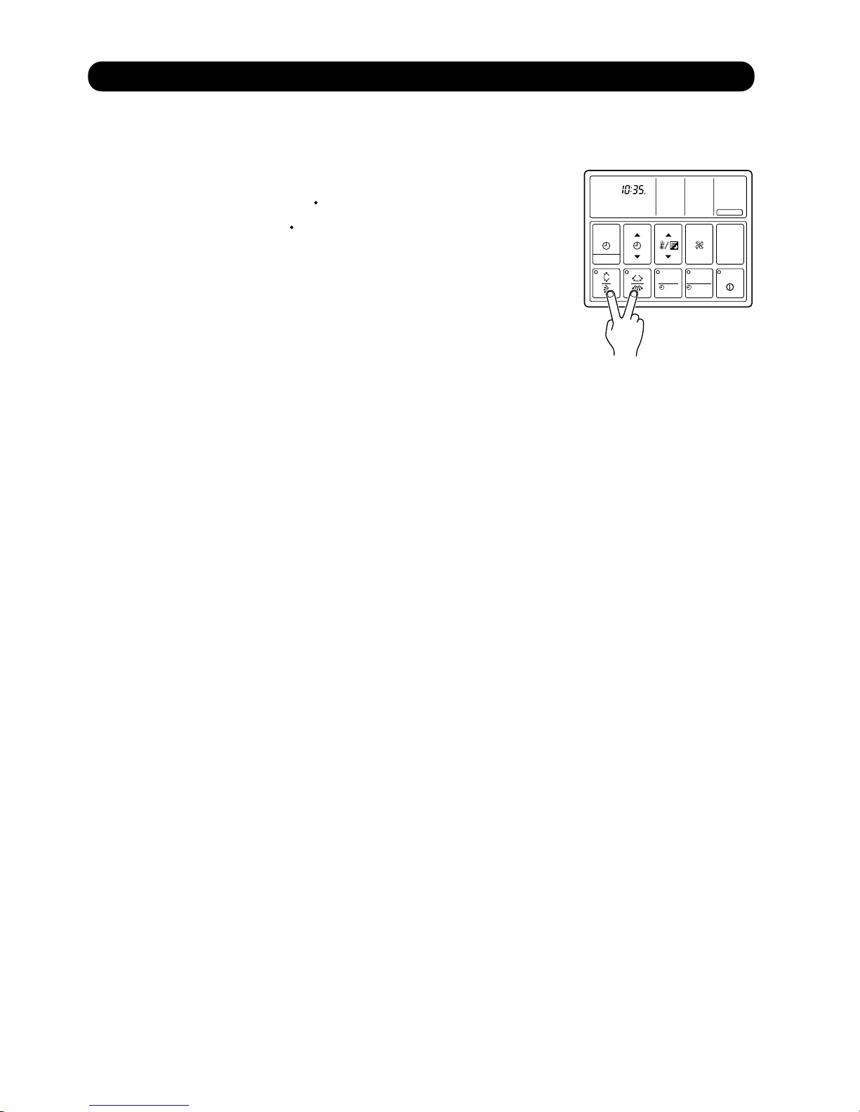
(2) To Use the ANTI FREEZE
Press the VERTICAL AIR FLOW DIRECTION and the HORIZONTAL AIR FLOW
DIRECTION SET Button at the same time for more than three seconds.
This operation is only enabled with the remote controller set to stop mode.
(3) To Stop the ANTI FREEZE
Press the VERTICAL AIR FLOW DIRECTION and the HORIZONTAL AIR FLOW
DIRECTION SET Button at the same time for more than three seconds once again.
This operation is only enabled with the remote controller set to stop mode.
(1) About the ANTI FREEZE
The freeze prevention fuction operates when the START/STOP button is pressed
and the remote controller is in stop mode (indoor unit is in stop mode). Whenever the room temperature falls to 5 C, it automatically sets the fan to low
speed and starts the heating operation. This operation stops when the temperature in the room rises reaches 8 C.
MASTER
CONTROL
FAN
CONTROL
TIMER
MODE
TEMP./DAY
SET TIME
CLOCK ADJUST
START/STOP
SET
DAY OFF
ZONE
ENERGY SAVE
COOL
FAN
DRY
HEAT
AUTOAUTO
CLOCK
OFF
OFF
ON
ON
C
F
NEXT DAY
DAY
TIMER
NON STOP
OFFON
TIMER
WEEKLY
ANTI FREEZE
CENTRAL
DAY OFF
DEFROST
TEST
12
4-6 ANTI FREEZE CONTROL
04-14
Page 75

After the power is turned on, the following operation is controlled automatically to control the most suitable refrigerant
charge according to the operation mode and operation conditions of each unit.
Electronic expansion valve control process.
The electronic expansion valve adjusts the opening by selecting the number of pulses from the rated capacity,operation
mode ( cool / heat ) and set temperature of each indoor unit.
(1) The air conditioner restarts with the previous setting operation.
(2) When the air conditioner restarts, the "THREE MINUTE DELAY FUNCTION" operates.
When the air conditioner restarts, the " THREE MINUTE DELAY FUNCTION " operates.
(3) When the air conditioner restarts for heating operation, the "COLD AIR DISCHARGE PREVENTION FUNCTION"
operates.
(1) When cooling and refrigerant circulation starts, the drain pump starts simultaneously.
(2) The drain pump operates continuously for 3 minutes after the refrigerant circulation stopped.
(3) When the refrigent circulation is stopped by a start of indoor heat exchanger frost provention
operation, the drain pump will turn off in 1 hour after the end of indoor heat exchanger frost
provention operation.
(4) When the water level in the drain pan rises up and then the float switch functions:
Microcomputer stops the refrigerant circulation and indoor fan motor operation.
Drain pump operates continuously for 3 minutes after the float switch is turned off.
(Almost condensing water may be drained)
(5) When the float switch turns ON continuously for 3 minutes, 'FAILURE INDICATION' operates.
(6) When the float switch turns OFF within 3 minutes, the unit starts cooling operation.
1
2
4-9 DRAIN PUMP OPERATION
4-8 AUTO RESTART
4-7 ELECTRONIC EXPANSION VALVE CONTROL
04-15
Page 76

5 . TROUBLE SHOOTING
TM
R407C
Page 77
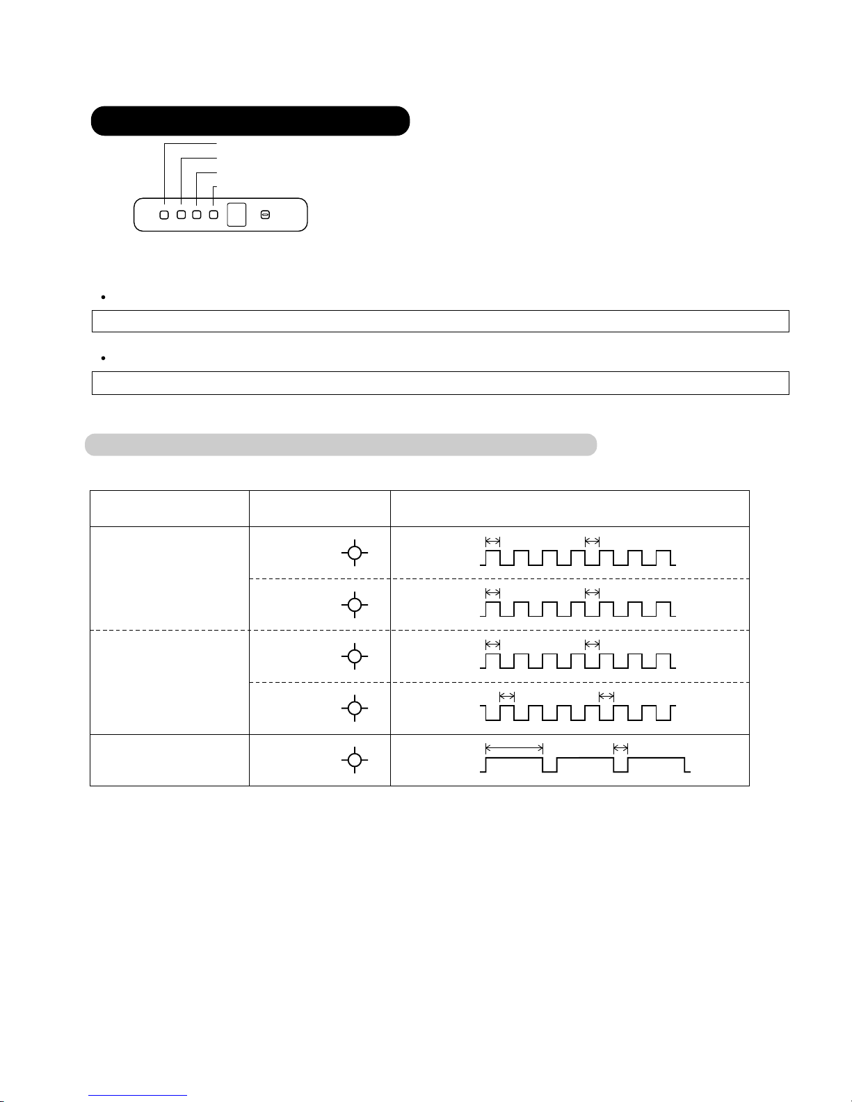
Operation can be checked by lighting and flashing of the LED (OPERATION, TIMER, SWING) of the grille display section.
Perform judgment in accordance with the following.
Test run
When the air conditioner is operating in test run mode, the OPERATION and TIMER lamps flash slowly at the same time.
Error
The OPERATION, TIMER and SWING lamps operate as follows (refer to 5-1-2) according to the error contents.
SWING
TIMER
OPERATION
MANUAL
AUTO
OPERATION LAMP (Red)
TIMER LAMP (Green)
SWING LAMP (Orange)
5-1 INDOOR UNIT
5. TROUBLESHOOTING
5-1-1 NORMAL OPERATION DISPLAY
OPERATING CONDITION INDICATOR LAMP FLASHING PATTERN
Operation
lamp (red)
Timer lamp
(green)
Operation
lamp (red)
Timer lamp
(green)
Operation
lamp (red)
Test run
*1 Stop
Defrosting operation
(Heating operation)
or
Oil recovery operation
*2
Note: Indicator lamps are on the front panel of the indoor unit.
*1: If a power failure occurred, the lamps of operation and timer flash on and off alternately when the power returns.
*2: While the indoor fan motor stops, the operation lamp flashes on and off.
1.0 sec 1.0 sec
ON
OFF
1.0 sec 1.0 sec
ON
OFF
1.0 sec 1.0 sec
ON
OFF
1.0 sec 1.0 sec
ON
OFF
3.0 sec 1.0 sec
ON
OFF
05-01
SWING
SWING LAMP (Orange)
(
Auto-restart disable
DIP SW 2-4 : OFF
( )
Page 78
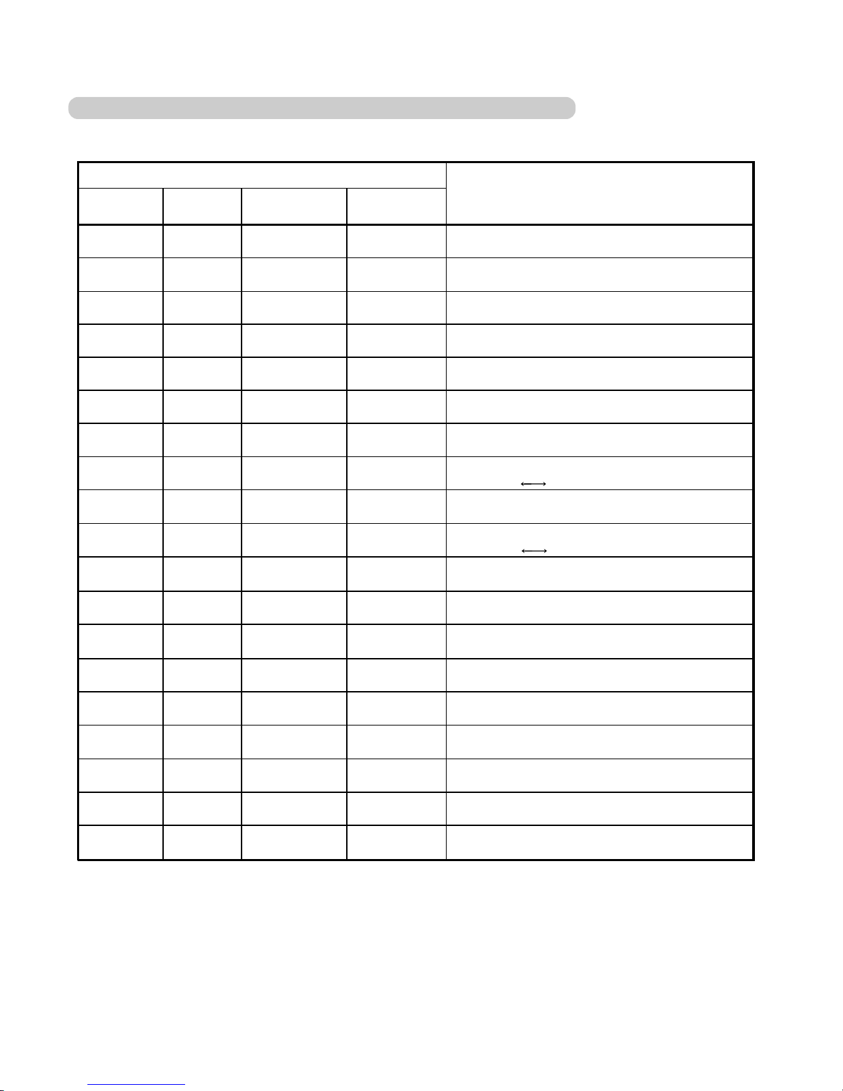
5-1-2 ABNORMAL OPERATION DISPLAY
05-02
Error display
OPERATION
lamp
0.1sec
0.1sec
TIMER
lamp
0.1 sec
0.1 sec
0.1 sec
VERTICAL
SWING lamp
0.1 sec
2 times
3 times
3 times
3 times
4 times
5 times
0.1 sec
0.1 sec
0.1 sec
0.1 sec
0.1 sec
1 times
5 times
6 times
0.1 sec
0.1 sec
2 times
3 times
1 times
2 times
7 times
0.1 sec
3 times
4 times
4 times
5 times
5 times
6 times
7 times
3 times
1 times
2 times
1 times
2 times
Error contents
Model information abnormal
Power supply frequency abnormal
Room temperature thermistor error
Indoor unit heat exchanger thermistor (inlet) error
Indoor unit heat exchanger thermistor (middle) error
Indoor unit heat exchanger thermistor (outlet) error
Drain abnormal
Communication error 1
(indoor unit
Microcomputer error
Indoor unit fan error
Blower temperature thermistor error
Outdoor unit error
EEPROM access error
EEPROM deletion error
Transmission error
Node setting error
Parallel communication error
Room temperature abnormal
0.1 sec
0.1 sec
0.1 sec
0.1 sec
0.1 sec
0.1 sec
0.1 sec
ON/OFF
ON/OFF
flashing
flashing
flashing
flashing
flashing
flashing
flashing
flashing
flashing
ON/OFF
ON/OFF
ON/OFF
ON/OFF
ON/OFF
ON/OFF
ON/OFF
ON/OFF
ON/OFF
ON/OFF
ON/OFF
ON/OFF
ON/OFF
ON/OFF
ON/OFF
ON/OFF
ON/OFF
ON/OFF
flashing
flashing
flashing
flashing
flashing
flashing
flashing
ON/OFF
flashing
flashing
flashing
flashing
flashing
flashing
flashing
flashing
flashing
flashing
HORIZONTAL
SWING lamp
Goes off
0.1 sec
ON/OFF
Goes off
Goes off
Goes off
Goes off
Goes off
Goes off
Goes off
Goes off
Goes off
Goes off
Goes off
Goes off
Goes off
Goes off
Goes off
Goes off
Wired/Simple remote controller)
Goes off
Goes off
Goes off
Goes off
Goes off
Goes off
Goes off
5 times
0.1 sec
4 times
Communication error 2
flashing
ON/OFF
flashing
Goes off
(indoor unit
Wired/Simple remote controller)
Page 79
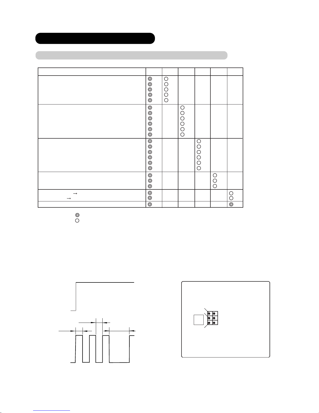
Display Type
LED 1
LED 2
LED 3
LED 4
LED 5
LED 6
Cooling operation
He
ating operation
Cooling main operation
Heating main operation
Same performance operation
Compressor output STEP1
Compressor output STEP2
Compressor output STEP4
Compressor output STEP5
Compressor output STEP6
Compressor output STEP7
Heat exchanger usage ca
pacity STEP1
Heat exchanger
usage
capacit
y STEP2
Heat
exchanger
usage
capacity STEP3
Heat
exchanger usage capacity STEP4
Heat exchanger usage capacity STEP5
Heat exchanger usage capacity STEP6
Oil recovery operation
Defrosting operation
Test run
Medium pressure
High pressure
Low pressure by-pass
Display Method
( )
: Lighted continuously
: 0.5sec ON/0.5sec OFF fl
ashing
: Flashing times
(1)
(2)
(3)
(4)
(5)
(1)
(2)
(3)
(4)
(5)
(6)
(1)
(2)
(3)
(4)
(5)
(6)
(1)
(2)
(3)
(1)
(2)
5-2 OUTDOOR UNIT
5-2-1 NORMAL OPERATING DISPLAY
OUTDOOR PRINTED CIRCUIT BOARD LAYOUTS
LED 6
LED 5
LED 4
LED 3
LED 2
LED 1
IC
0.5SEC
0.5SEC
2SEC
ON
OFF
ON
OFF
display
LED 1
LED 2-6
Under initialization of expansion valve
Low pressure by-pass
Operation
05-03
Page 80
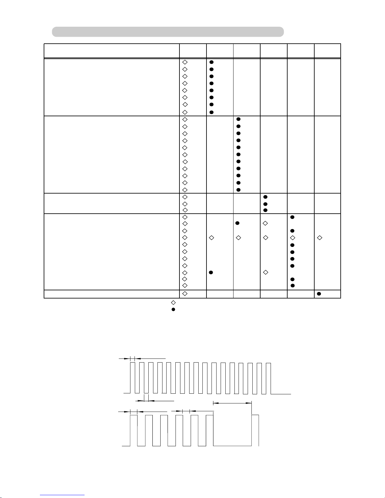
Display method
: 0.1 sec ON / 0.1 sec OFF flashing
: 0.3 sec ON / 0.3 sec OFF flashing
: Flashing times
( )
{
5-2-2 ABNORMAL OPERATION DISPLAY
Error display
0.1sec
0.1sec
0.1 sec
ON/OFF
repeated
0.3sec
0.3sec
2sec
ON
ON
OFF
OFF
LED 1
LED 2-6
Display type
Liquid pressure sensor error
Heat exchange outlet thermistor 3 error
Heat exchange inlet thermistor 1 error
Heat exchange inlet thermistor 2 error
Heat exchange inlet thermistor 3 error
Suction thermistor error
Outdoor thermistor error
Model information error
LED 1
LED 2
LED 3 LED 4
LED 5
LED 6
(1)
(2)
(3)
(4)
(5)
(6)
(7)
(9)
(1)
(2)
(3)
(4)
(5)
(6)
(7)
(8)
(9)
(10)
(11)
(1)
(2)
(7)
(1)
(3)
(4)
(6)
(7)
(1)
Power supply frequency abnormal
Transmission error
Node setting error
(2)
(8)
(9)
Compressor 1 error
Compressor 2 error
Compressor 3 error
Discharge temperature 1 error
Discharge temperature 2 error
Discharge temperature 3 error
High-pressure error
Pump down error
Discharge temperature thermistor 1 error
Discharge temperature thermistor 2 error
Discharge temperature thermistor 3 error
Heat exchange outlet thermistor 1 error
Heat exchange outlet thermistor 2 error
Discharge pressure sensor error
Oil recovery error
Reverse phase blocker error
EEPROM access error
EEPROM deletion error
Outdoor unit circuit bord error 1
Outdoor unit circuit bord error 2
Indoor unit error
Reverse phase blocker error
Outdoor unit circuit bord error 2
05-04
Page 81

Error Code
Error Code
Error contents
Model information abnormal
No error
Power supply frequency abnormal
EEPROM access error
EEPROM deletion error
Room temperature themistor error
Indoor unit heat exchanger themistor
Indoor unit heat exchanger themistor
Indoor unit heat exchanger themistor
Blower temperature themistor error
Drain abnormal
Room temperature abnormal
Indoor unit fan error
Transmission error
Node setting error
Parallel communication error
5-3 REMOTE CONTROLLER
MASTER
CONTROL
FAN
CONTROL
TIMER
MODE
TEMP./DAY
SET TIME
CLOCK ADJUST
START/STOP
SET
DAY OFF
ZONE
ENERGY SAVE
MASTER
CONTROL
FAN
CONTROL
TIMER
MODE
TEMP./DAY
SET TIME
CLOCK ADJUST
START/STOP
SET
DAY OFF
ZONE
ENERGY SAVE
COOL
CLOCK
C
NON STOP
Outdoor unit error
(middle) error
(inlet) error
(outlet) error
05-05
Remote controller
address
SET
SET
Error Code
Remote controller
address
If there is a problem with the air conditioner it will stop
running and " EE:EE " will be displayed.
(1) If the operation lamp is on then press
button to turn it off.
(2) Press the
and the
buttons at the same time
for more than three seconds to start the self diagnosis
check.
An error code will be displayed display area.
(3) Press the
and the
buttons again for more than
three seconds to end the self diagnosis check.
Error code history can be displayed. Please refer to
"Installation Instruction Sheet" of the remote controller.
If there is a problem with the air conditioner, it will
stop running and " EE:EE " will be displayed instead
of the clock.
Error code displayed on wired or simple remote controller
(1) If the operation lamp is on then press START/
STOP button to turn it off.
(2) Press the SET TIMER button ( ) and SET
TEMP./DAY button ( ) at the same time for more
than three seconds to start the self diagnosis check.
An error code will be displayed in the clock display area.
(3) Press the SET TIMER button ( ) and SET
TEMP./DAY button ( ) again for more than three
seconds to end the self diagnosis check.
5-3-1 WIRED REMOTE CONTROLLER
5-3-2 SIMPLE REMOTE CONTROLLER
Error code history can be displayed when UTB- LB type
wired remote controllers is used.Please refer to
"Installation Instruction Sheet" of the controller.
Page 82

If the and the number for the central control number flash during operation, there is an
error at the relevant remote control group. Start the error monitor, identify the error and remove the
cause.
When the error monitor is started, the following can be performed.
The error code for each remote control group (indoor units) is displayed.
Up to two of the past error codes are displayed for each of the indoor units, the outdoor units and
the central remote controller group.
(1) Press
CHECK
to start the error monitor.
The LCD changes to the error monitor screen.
(2) Press to select the central control
number for which its details of the error contents
are to be confirmed. (The number of the caus-
ing the error is flashing.)
(3) Press to select the display mode for the error
code.
Each press of will switch the display as shown
below.
Current error code First previous error code
Second previous error code
CHECK
ACL
MASTER
ENERGY ANTI
FAN
TIMER
SET
TIMER
DELETE
TIMER
DAY
CLOCK
ADJUST
DAY OFF
TEMP.
MEMORY
OPERATION
MEMORY
TEST
SET
CENTRAL
DELETE
BACK
GROUP
ZONE
ON OFF
TIME
CONTROL
CONTROL
FILTER
RESET
CONTROL
FREEZE
COPY
TIMER
MODE
SAVE
SETTING SETTING
5-3-3 CENTRAL REMOTE CONTROLLER
(3) (2)
(4) (1), (5)
05-06
Page 83

(4) Press to select the indoor units in the remote control group selected in 3.
TIME
Continue pressing , the error codes for the outdoor unit and the central re-
TIME
mote controller are displayed. Each of the displays is shown below.
(5) Press
CHECK
again to end the error monitor.
If there have been multiple
errors for one unit, continually
pressing will display the
TIME
error codes in sequence.
When all the error codes have
been displayed, the display
will switch to the next unit.
If there is no error in the
central control number selected
in 3, the display will not change
when is pressed. "00"
TIME
displayed means "no errors".
"The refrigerant system address and indoor unit
address are displayed."
"Refrigerant system address" and "-0" are displayed.
The "C" code and the central remote controller
address are displayed.
TIME
TIME
TIME
Indoor unit
error display
Outdoor unit
error display
Central remote
control error
display
05-07
Page 84

Error
Code
Indoor unit error Outdoor unit error Central remote controller
00
01 – – –
02 Model information abnormal
No error No error No error
Model information error
Printed circuit board error (Control panel)
03
Microcomputer communication error Microcomputer communication error
Printed circuit board error (Transmission adaptor)
04
Power supply frequency abnormal Power supply frequency abnormal Memory error
05
– Reverse phase blocker error Node setting error
06
EEPROM access error Parallel communication error
07
EEPROM deletion error – –
08
– – –
09
Room temperature thermistor error Compressor 1 error –
0A
Heat exchanger thermistor (middle) error
Compressor 2 error –
0B
Heat exchanger thermistor (inlet) error
Compressor 3 error –
0C
Heat exchanger thermistor (outlet) error
– –
0D
Blower temperature thermistor error
Discharge temperature thermistor 1 error
–
0E
–
Discharge temperature thermistor 2 error
–
0F
–
Discharge temperature thermistor 3 error
–
10
–
Outdoor temperature thermistor error
–
11
Drain abnormal
Heat exchanger inlet thermistor 1 error
–
12
Room temperature abnormal
Heat exchanger inlet thermistor 2 error
–
13
Indoor unit fan error
Heat exchanger inlet thermistor 3 error
–
14
–
Heat exchanger outlet thermistor 1 error
–
15
–
Heat exchanger outlet thermistor 2 error
–
16
–
Heat exchanger outlet thermistor 3 error
–
17
– Suction thermistor error –
18
Standard wired remote controller communication error 1,2
– –
19
– Discharge pressure sensor error –
1A
– Liquid pressure sensor error –
1B
– Suction pressure sensor error –
1C
– Connection error
1D
– Initial setting error
1E
–
–
–
– Manual storing 2 error
1F
Transmission error Transmission error Transmission error
20
– – –
21
– Discharge temperature 1 error Software error (Output)
22
– Discharge temperature 2 error Software error (Input)
23
– Discharge temperature 3 error –
24
– High-pressure error –
25
– Low-pressure error –
26
–
27
–
28
–
–
–
Pump down error
–
–
–
Error code displayed on central remote controller
EEPROM access error
05-08
Page 85

If there is a problem with the network convertor(UTR-YSSA), an error code will appear on D129 of print circuit board.
No error (operation mode)
Initial setting
Circuit board error 1
Circuit board error 2
Transmission error with wired RC
Transmission error with indoor unit
Transmission error with VRF system
Software error
Indoor or outdoor unit error
Error code displayed on network convertor
5-4 NETWORK CONVERTOR
Error code
Error contents
05-09
Page 86

ERROR
ERROR CONTENTS
CAUSE
COUNTERMEASURE
00 No errors
02
1. Error occurrence condition
When power is turned on.
Error for the model informa tion, which is memorized
in EEPROM, occurs.
2. Relevant operation
1) Relevant indoor unit is
stopped (Not started).
2) Error is displayed on LED of
indoor unit or output to
communication bus line.
3. Clearance
Model information, which is
memorized in EEPROM is
recovered normally.
1. Error occurrence condition
Communication between two
microcomputers on indoor
unit control printed circuit
board is not performed
correctly.
2. Relevant operation
1) Relevant indoor unit is
stopped (not started).
2) Error is displayed on LED of
indoor unit or output to
communication bus line.
3. Clearance
The communication between
microcomputers is
performed correctly.
Replace control printed circuit board of
indoor unit.
1. When power is turned off, and then
turned on again:
1) If error doesn't occur, printed circuit
board is normal. Then, remove
noise sources near indoor unit.
2) If error occurs again, remove noise
sources and take measure with the
following countermeasure No.2.
2. Replace indoor unit control printed
circuit board.
Model information is not
memorized or erased because
of some reason.
1. Effect of extraneous noise
2. Control printed circuit board
of Indoor unit is faulty.
Model
information
error
03
Microcomputer
communication
error
1. Error occurrence condition
When control printed circuit
board of Indoor unit detects
frequency, which is not
specified.
2. Relevant operation
1) Relevant indoor unit is
stopped (not started).
2) Error is displayed on LED of
indoor unit or output to
communication bus line.
3. Clearance
Control printed circuit board
of Indoor unit detects the
specified frequency.
Check power supply frequency and
apply the power whose frequency is
within the specified frequency.
Power supply frequency is in
the following range. Lower than
45Hz or Higher than 65Hz.
04
Power supply
frequency
abnormal
1. Error occurrence condition
After indoor unit operation is
started, EEPROM cannot
be accessed because of
disturbance or device error.
2. Relevant operation
Error is displayed on LED
of indoor unit.
3. Clearance
Access to EEPROM is
performed correctly.
1. Remove noise sources near indoor
unit.
2. Replace control printed circuit board
of indoor unit.
EEPROM cannot be accessed
because of disturbance, device
error, etc.
06
EEPROM
access error
INDOOR UNIT TROUBLESHOOTING
ERROR
CODE
5-5 ERROR CODE & TROUBLESHOOTING
5-5-1 TROUBLE SHOOTING WITH ERROR CODE
05-10
Page 87

ERROR
ERROR CONTENTS
CAUSE
COUNTERMEASURE
07
1. Error occurrence condition
After indoor unit operation is
started, error for model infor mation, which is memorized
on EEPROM, occurs.
2. Relevant operation
1) Relevant indoor unit is
stopped.
2) Error is displayed on LED of
indoor unit.
3. Clearance
Model information, which is
memorized on EEPROM
is recovered.
1. Error occurrence condition
The condition of thermistor,
which is short or open, is
detected.
2. Relevant operation
Indoor unit stopped. Error is
displayed on LED of indoor
unit and output to
communication bus line.
3. Clearance
Thermistor detection is
other than short or open.
Replace control printed circuit board
of indoor unit.
1. Check if the connector of Room
temperature thermistor loosens or
comes off.
2. Check the resistance of Room
temperature thermistor. If it's not
normal, replace the thermistor.
Model information is not
memorized, or erased because
of some reasons.
1. Connector connection is
faulty.
2. Room Temperature
thermistor is faulty.
EEPROM
deletion error
09 Room
temperature
thermistor error
1. Error occurrence condition
The condition of thermistor,
which is short or open, is
detected.
2. Relevant operation
Indoor unit is stopped. Error
is displayed on LED of
indoor unit and output to
communication bus line.
3. Clearance
Thermistor detection is
other than short or open.
0A
Heat exchanger
thermistor
(middle) error
1. Check if the connector of Heat
exchanger thermistor (middle)
loosens or comes off.
2. Check the resistance of heat
exchanger thermistor (middle). If it's
not normal, replace thermistor.
1. Connector connection is
faulty.
2. Heat exchanger thermistor
(middle) is faulty.
2. Heat exchanger thermistor
(inlet) is faulty.
1. Error occurrence condition
The condition of thermistor,
which is short or open, is
detected.
2. Relevant operation
Error is displayed on LED
of indoor unit.
3. Clearance
Thermistor detection is
other than short or open.
0B
Heat exchanger
thermistor
(inlet) error
1. Check if the connector of heat
exchanger thermistor (inlet) loosens
or comes off.
1. Connector connection is
faulty.
2. Heat exchanger thermistor
(outlet) is faulty.
0C
Heat exchanger
thermistor
(outlet) error
1. Connector connection is
faulty.
2. Check the resistance of heat
exchanger thermistor (inlet). If it's
not normal, replace thermistor.
1. Error occurrence condition
The condition of thermistor,
which is short or open, is
detected.
2. Relevant operation
Error is displayed on LED
of indoor unit.
3. Clearance
Thermistor detection is
other than short or open.
1. Check if the connector of heat
exchanger thermistor (outlet) loosens
or comes off.
2. Check the resistance of heat
exchanger thermistor (outlet). If it's
not normal, replace thermistor.
ERROR
CODE
05-11
Page 88

ERROR
CONTENTS
CAUSE
COUNTERMEASURE
0D
1. Error occurrence condition
The condition of thermistor,
which is short or open, is
detected.
2. Relevant operation
Indoor unit is stopped. Error is
displayed on LED of indoor unit
and output to communication
bus line.
3. Clearance
Thermistor detection is other
than short or open.
1. Error occurence condition
Float SW is ON
continuously for 3 minutes.
2. Relevant operation
Indoor unit is stopped. Error
is displayed on LED of
indoor unit and output to
communication bus line.
3. Clearance
Float SW is OFF.
1. Clean drain hose.
2. Clean drain outlet.
3. Check drain pump operation. If it's
faulty, replace pump.
4. If float SW is shorted, replace SW.
1. Drain hose is clogged.
2. Drain outlet is clogged.
3. Drain pump is faulty.
4. Float SW operation is faulty
(short)
Blower
temperature
thermistor
error
11 Drain abnormal
1. Error occurence condition
Room temperature
thermistor detects higher
than 60 C continuously for
30 minutes or longer during
indoor unit operation.
2. Relevant operation
Indoor unit is stopped. Error
is displayed on LED of
indoor unit and output to
communication bus line.
3. Clearance
It's cleared by turning off the
power .
12
Room
temperature
abnormal
1. Error occurr condition
Fan speed feedback of large
ceiling type, slim body cassette
type and ceiling wall type is
lower than 1/3 of target speed.
2. Relevant operation
Indoor fan is stopped, error
is displayed on LED of indoor
unit and out put to communica tion bus line.
3. Clearance
It's cleared by turning off the
power.
13
Indoor unit fan
error
1. Check if the connector of blower
temperature thermistor loosens or
comes off.
2. Check resistance of blower
temperature thermistor. If it's not
normal, replace thermistor.
1.Connector connection is
faulty.
2. Blower temperature
thermistor is faulty.
1. Check if the connector of room tempe rature thermistor loosens or comes off.
2. Check resistance of room temperature
thermistor. If it's normal, replace
thermistor.
1. Connector connection is
faulty.
2. Room temperature
thermistor is faulty.
1. Check the wiring of indoor fan motor
lead wire .
2. Check if rated power supply voltage
is applied.
1. Indoor fan motor lead wire
connection is faulty.
2. Power supply voltage
abnormal.
1. Error occurrence condition
Communication can not be
performed between standard
wired remote controller and
indoor unit or between indoor
units in same remote controller
group for a certain time.
2. Relevant operation
Error is displayed on LED of
indoor unit.
3. Clearrance
Standard wired remote
controller communication
is recovered.
18
Standard wired
R.C. communication error 1,2
1. Check if communication line is
connected to each indoor unit. Check
if communication line is disconnected
or loosen.
2. Replace control printed circuit board of
indoor unit.
3. Replace standard wired remote
controller printed circuit board.
1. Communication line is not
connected, connection fault,
or disconnection.
2. Indoor unit control printed
circuit board is faulty.
3. Standard wired remote
controller printed circuit
board is faulty.
ERROR
CODE
05-12
Page 89

ERROR
ERROR CONTENTS
CAUSE
COUNTERMEASURE
1F
1. Error occurrence condition
Communication between
indoor unit and outdoor unit
cannot be performed for a
certain time.
2. Relevant operation
Current operation is
continued.
Error is displayed on
standard wired remote
controller, and displayed on
indoor unit LED.
3. Clearance
Communication between
indoor unit and outdoor unit
is recovered.
1. Error occurrence condition
Indoor unit communication
printed circuit board is not
initialized normally.
2. Relevant operation
Error is displayed on
standard wired remote
controller and displayed on
LED of indoor unit.
3. Clearance
Indoor unit communication
printed circuit board is
initialized correctly.
1. When power turned OFF and turned
ON again:
1) If error doesn't occur, printed circuit
board is normal. Then, remove
noise sources near indoor unit.
2) If error occurs again, remove noise
sources and take measure with the
following countermeasure No.2-3.
2. Replace printed circuit boards with
following procedures,
and check the operation.
1 Replace Indoor unit communication
printed circuit board.
2 Replace Indoor unit control printed
circuit board.
1. Effect of extraneous noise.
2. Printed circuit board is faulty.
Transmission
error
20
Node setting
error
1. When power is turned OFF and
turned ON again:
1) If error doesn't occur, printed circuit
board is normal. Then, remove noise
sources near outdoor unit.
2) If error occurs again, remove noise
sources and take measure with the
following countermeasure No.2-4.
2. Check if communication line is
connected to all indoor unit. Check if
communication line is disconnected.
3. Check the insertion of indoor unit
communication printed circuit board
and outdoor unit communication
printed circuit board.
4. 1) If communication of some indoor
units in same refrigerant system is
abnormal and the compressor
operates, replace printed circuit
boards with following procedures
and check the operation:
1 Replace Indoor unit communication
printed circuit board.
2 Replace Indoor unit control
printed circuit board.
2) If communication of all indoor units
in same refrigerant system is
abnormal and the compressor does
not operate, replace printed circuit
boards with following procedures and
check the operation:
1 Replace Outdoor unit communication
printed circuit board.
2 Replace Outdoor unit control printed
circuit board.
3 Replace Indoor unit communication
printed circuit board.
4 Replace Indoor unit control printed
circuit board.
2. Communication line is not
connected, connection fault,
or disconnection.
3. Insertion for communication
printed circuit board of
indoor unit or outdoor unit
is faulty.
4. Printed circuit board is faulty.
1. Effect of extraneous noise.
ERROR
COCE
05-13
Page 90

ERROR
ERROR CONTENTS
CAUSE
COUNTERMEASURE
1. Error occurrence condition
Communication between
indoor unit control printed
circuit board and indoor unit
communication printed
circuit board is not
performed normally.
2. Relevant operation
1) Current operation is
continued. Error is displayed
on standard wired remote
controller, and displayed on
LED of indoor unit.
2) If error continues for 90
seconds after it's
occurrence, a new
transmission error
(1F) is output.
3. Clearance
Communication is
performed correctly between
indoorunit control printed
circuit board and indoor unit
communication printed
circuit board.
Error occurs on outdoor unit
in same refrigerant system.
21 Parallel
communication
error
1. When power is turned OFF and turned
ON again:
1) If error doesn't occur, printed circuit
board is normal. Then, remove noise
sources near indoor unit.
2) If error occurs again, remove noise
sources and take measure with the
following countermeasure No.2-3.
2. Check the insertion of indoor unit
communication printed circuit board.
3. Replace printed circuit boards with
following procedure, and check
the operation.
(1) Replace Indoor unit communication
printed circuit board.
(2) Replace Indoor unit control printed
circuit board.
1. Effect of extraneous noise.
32 Outdoor unit
error
See "Outdoor unit troubleshooting".
Outdoor unit is faulty.
2. Indoor unit communication
board insertion is faulty.
3. Printed circuit board is faulty.
ERROR
CODE
05-14
Page 91

ERROR
ERROR CONTENTS
CAUSE
COUNTERMEASURE
00 No errors
02
1. Error occurrence condition
When power is turned on,
error occurs in model
information, which is
memorized in EEPROM.
2. Relevant operation
1) All compressors are
stopped (not started).
2) Error is displayed on LED of
outdoor unit and output to
communication bus line.
3. Clearance
Model information, which is
memorized in EEPROM
is recovered.
1. Error occurrence condition
Communication between
two microcomputers on
outdoor unit control printed
circuit board is not
performed normally.
2. Relevant operation
1) All compressors is stopped
(not started).
2) Error is displayed on LED of
outdoor unit and output to
communication bus line.
3. Clearance
Communication between
microcomputers is
recovered.
Replace outdoor unit control printed
circuit board.
1. When power is turned OFF and turned
ON again:
1) If error doesn't occur, printed circuit
board is normal. Then, remove noise
sources near outdoor unit.
2) If error occurs again, remove noise
sources and take measure with the
following countermeasure No.2.
2. Replace outdoor unit control printed
circuit board.
Model information is not
memorized, or erased because
of some reason.
1. Effect of extraneous noise
2. Outdoor unit control printed
circuit board is faulty.
Model
information
error
03
Circuit board
error
1. Error occurrence condition
Outdoor unit control printed
circuit board detects
frequency outside of rating.
2. Relevant operation
1) All compressors are
stopped (not started).
2) Error is displayed on LED of
outdoor unit and output to
communication bus line.
3. Clearance
Outdoor unit control printed
circuit board detects the
specified frequency.
Check power supply frequency and
apply the power whose frequency is
within the specified frequency.
04
Power supply
frequency
abnormal
1. Check power supply wiring.
2. Check power supply wiring. If there
are no mistakes, replace outdoor unit
control printed circuit board.
1. Reverse phase wiring.
2. Reverse phase prevention
circuit is faulty.
05
Reverse phase
blocker error
Power supply frequency is in
the following range. Lower than
45Hz or higher than 65Hz.
1. Error occurrence condition
Reverse phase prevention
circuit detects the wrong
phase of power supply or
the correct power supply
input is not detected.
2. Relevant operation
1) All compressors are
stopped.
2) Error is displayed on LED of
outdoor unit and output to
communication bus line.
3. Clearance
Reverse phase prevention
circuit doesn't detect
reverse phase input.
OUTDOOR UNIT TROUBLESHOOTING
ERROR
CODE
05-15
Page 92

ERROR
ERROR CONTENTS
CAUSE
COUNTERMEASURE
06
1. Error occurrence condition
After outdoor unit operation
is started, EEPROM cannot
be accessed because of
disturbance or device error.
2. Relevant operation
Error is displayed on LED of
outdoor unit. *Outdoor unit
operation is not controlled.
3. Clearance
EEPROM can be accessed
correctly.
1. Remove noise sources near outdoor
unit.
2. Replace outdoor unit control printed
circuit board.
EEPROM cannot be accessed
because of disturbance, device
error, etc.
Replace outdoor unit control printed
circuit board.
Model information is not
memorized, or erased for some
reason.
EEPROM
access error
07 EEPROM
deletion error
09 Compressor 1
error
1. Check if the wiring of discharge
temperature sensor THD1 loosens or
comes off. And check the resistance
of sensor. If it's abnormal,
replace sensor.
2. Check compressor power relay 1. If
it's abnormal, replace power relay.
3. Check CN24 (compressor 1) 12V
voltage output on outdoor unit control
printed circuit board. If it's abnormal,
replace printed circuit board.
4. Check magnetic contactor 1. If it's
abnormal, replace contactor.
5. Check additional refrigerant amount
and recharge suitable refrigerant.
6. Temporary data transmission trouble
due to Effect of extraneous noise, etc.
Operation is not affected.
7. Compressor overload operation
Check "High-pressure error". Motor
protector is reset at 61 C +/-9 C.
8. Check compressor. If it's faulty,
replace compressor.
1. Discharge temperature
sensor THD1 is faulty.
3. Outdoor unit control printed
circuit board is faulty.
4. Magnetic contactor 1
is faulty.
5. Lack of refrigerant.
6. After 2 and half an hours
have elapsed since error is
displayed, error detection
is performed again and error
is not displayed.
7. Compressor motor protector
is operated.
8. Compressor is faulty.
1. Error occurrence condition
After outdoor unit operation
is started, error occurs in
model information, which is
memorized in EEPROM.
2. Relevant operation
1) All compressors are stopped.
2) Error is displayed on LED of
outdoor unit.
3. Clearance
Model information, which is
memorized in EEPROM is
recovered.
1. Error occurrence condition
After thirty minutes has
elapsed since compressor 1
starts to work, discharge
temperature 1 does not
reach to outdoor
temperature plus 10 C.
2. Relevant operation
1) After compressor error
occurs, compressor
recovery operation is
performed. However, if
defrosting control or oil
recovery operation is
performed, compressor
recovery is not operated.
2) Error is displayed on LED of
outdoor unit and output to
communication bus line.
3. Clearance
When 2 hours have elapsed
after error occurrence.
*Counting of 2-hour counter
starts if error occurs on any
compressors.
Error is cleared by turning
power off.
2. Compressor power relay 1
is faulty.
ERROR
CODE
05-16
Page 93
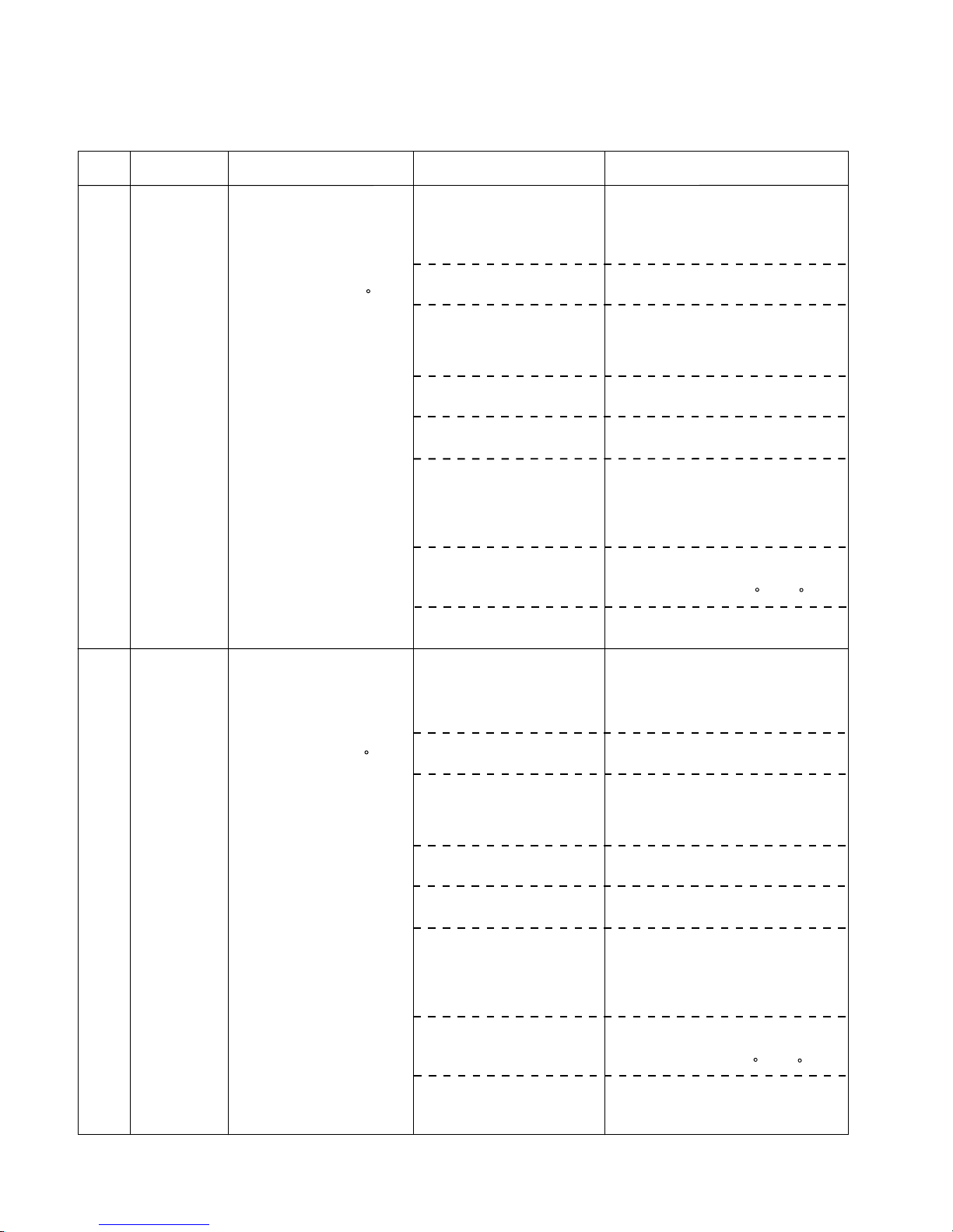
ERROR
CONTENTS
CAUSE
COUNTERMEASURE
Compressor 2
error
1. Check if the wiring of discharge
temperature sensor THD2 loosens or
comes off. And check the resistance of
sensor. If it's abnormal, replace sensor.
2. Check compressor power relay 2. If
it's abnormal, replace power relay.
3. Check CN25 (compressor 2) 12V
voltage output on outdoor unit control
printed circuit board. If it's abnormal,
replace printed circuit board.
4. Check magnetic contactor 2. If it's
abnormal, replace contactor.
5. Check additional refrigerant amount
and recharge suitable refrigerant.
6. Temporary data transmission trouble
due to affect of noise, etc. Operation is
not affected.
7. Compressor overload operation
Check "High-pressure error". Motor
protector is reset at 61 C +/-9 C.
8. Check compressor. If it's faulty,
replace compressor.
1. Discharge temperature
sensor THD2 is faulty.
3. Outdoor unit control printed
circuit board is faulty.
4. Magnetic contactor 2 is
faulty.
5. Lack of refrigerant.
6. After 2 and half an hours
have elapsed since error is
displayed, error detection
is performed again and error
is not displayed.
7. Compressor motor protector
is operated.
8. Compressor is faulty.
1. Error occurrence condition
After thirty minutes have
elapsed since compressor 2
starts to work, discharge
temperature 2 does not
reach to outdoor
temperature plus 10 C.
2. Relevant operation
1) After compressor error
occurs, compressor
recovery operation is
performed. However, if
defrosting control or oil
recovery operation is
performed, compressor
recovery is not operated.
2) Error is displayed on LED of
outdoor unit and output to
communication bus line.
3. Clearance
When 2 hours have elapsed
after error occurrence.
*Counting of 2-hour counter
starts if error occurs on any
compressors. Error is
cleared by turning power off.
2. Compressor power relay 2
is faulty.
0A
Compressor 3
error
1. Check if the wiring of discharge
temperature sensor THD3 loosens or
comes off. And check the resistance
of sensor. If it's abnormal, replace
sensor.
2. Check compressor power relay 3. If
it's abnormal, replace power relay.
3. Check CN26 (compressor 3) 12V
voltage output on outdoor unit control
printed circuit board. If it's abnormal,
replace printed circuit board.
4. Check magnetic contactor 3. If it's
abnormal, replace contactor.
5. Check additional refrigerant amount
and recharge suitable refrigerant.
6. Temporary data transmission trouble
due to affect of noise, etc. Operation
is not affected.
7. Compressor overload operation
Check "High-pressure error". Motor
protector is reset at 61 C +/-9 C.
8. Check compressor. If it's faulty,
replace compressor.
1. Discharge temperature
sensor THD3 is faulty.
3. Outdoor unit control printed
circuit board is faulty.
4. Magnetic contactor 3 is
faulty.
5. Lack of refrigerant.
6. After 2 and half an hours
have elapsed since error is
displayed, error detection
is performed again and error
is not displayed.
7. Compressor motor protector
is operated.
8. Compressor is faulty.
1. Error occurrence condition
After thirty minutes have
elapsed since compressor 3
starts to work, discharge
temperature 3 does not
reach to outdoor
temperature plus 10 C.
2. Relevant operation
1) After compressor error
occurs, compressor
recovery operation is
performed. However, if
defrosting control or oil
recovery operation is
performed, compressor
recovery is not operated.
2) Error is displayed on LED of
outdoor unit and output to
communication bus line.
3. Clearance
When 2 hours has elapsed
after error occurrence.
*Counting of 2-hour counter
starts if error occurs on any
compressors.
Error is cleared by turning
power off.
2. Compressor power relay 3 is
faulty.
0B
ERROR
CODE
05-17
Page 94
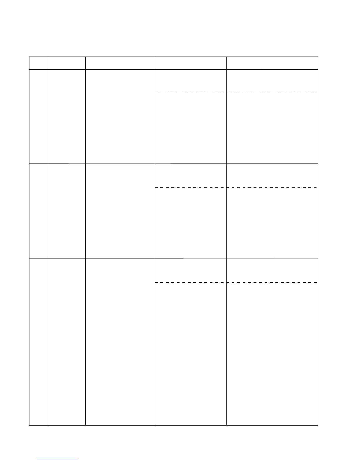
ERROR
CONTENTS
CAUSE
COUNTERMEASURE
Discharge
temperature
thermistor 1
error
1. Check if the connector of discharge
temperature thermistor THD1 loosens
or comes off.
2. Check the resistance of discharge
temperature thermistor THD1. If it's
abnormal, replace thermistor.
1. Connector contact is faulty.
1. Error occurrence condition
Thermistor condition, which
is short or open, is detected.
2. Relevant operation
1) Compressor 1 is stopped.
2) Error is displayed on LED of
outdoor unit and output to
communication bus line.
3. Clearance
Thermistor detection is
other than short or open.
*Detection is performed when
Compressor continues to
operate for 5 minutes or
longer.
2. Discharge temperature
thermistor THD1 is faulty.
0D
Discharge
temperature
thermistor 2
error
1. Check if the connector of discharge
temperature thermistor THD2 loosens
or comes off.
2. Check the resistance of discharge
temperature thermistor THD2. If it's
abnormal, replace thermistor.
1. Connector contact is faulty.
1. Error occurrence condition
Thermistor condition, which
is short or open, is detected.
2. Relevant operation
1) Compressor 2 is stopped.
2) Error is displayed on LED of
outdoor unit and output to
communication bus line.
3. Clearance
Thermistor detection is
other than short or open.
*Detection is performed when
Compressor continues to
operate for 5 minutes or
longer.
2. Discharge temperature
thermistor THD2 is faulty.
0E
Discharge
temperature
thermistor 3
error
1. Check if the connector of discharge
temperature thermistor THD3 loosens
or comes off.
2. Check the resistance of discharge
temperature thermistor THD1. If it's
abnormal, replace thermistor.
1. Connector contact is faulty.
1. Error occurrence condition
Thermistor condition, which
is short or open, is detected.
2. Relevant operation
1) Compressor 3 is stopped.
2) Error is displayed on LED of
outdoor unit and output to
communication bus line.
3. Clearance
Thermistor detection is
other than short or open.
*Detection is performed when
Compressor continues to
operate for 5 minutes or
longer.
2. Discharge temperature
thermistor THD3 is faulty.
0F
ERROR
CODE
05-18
Page 95
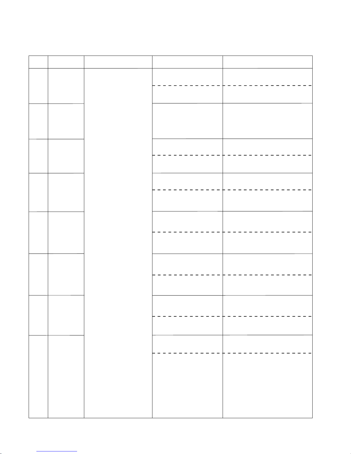
ERROR
CONTENTS
CAUSE
COUNTERMEASURE
Outdoor
thermistor error
1. Check if the connector of outdoor
temperature thermistor THH0 loosens
or comes off.
2. Check the resistance of outdoor
temperature thermistor THH0. If it's
abnormal, replace thermistor.
1. Connector contact is faulty.
2. Outdoor temperature
thermistor THH0 is faulty.
10
Suction
thermistor error
11 Heat exchanger
inlet
thermistor 1
error
1. Check if the connector of heat
exchanger inlet thermistor THHI1
loosens or comes off.
2. Check the resistance of heat
exchanger inlet thermistor THHI1. If it's
abnormal, replace thermistor.
1. Connector contact is faulty.
2. Heat exchanger inlet
thermistor THHI1 is faulty.
Heat exchanger
inlet
thermistor 2
error
1. Connector contact is faulty.
2. Heat exchanger inlet
thermistor THHI2 is faulty.
Heat exchanger
inlet
thermistor 3
error
1. Connector contact is faulty.
2. Heat exchanger inlet
thermistor THHI3 is faulty.
Heat exchanger
outlet
thermistor 1
error
1. Error occurrence condition
Each thermistor condition,
which is short or open,
is detected.
2. Relevant operation
1) All Compressors are
stopped.
*For suction temperature
thermistor error,
compressors are not stopped.
2) Error is displayed on LED of
outdoor unit and output to
communication bus line.
*For suction temperature
thermistor error, error is only
displayed on LED of outdoor
unit.
3. Clearance
Thermistor detection is
other than short or open.
1. Connector contact is faulty.
2. Heat exchanger outlet
thermistor THHO1 is faulty.
1. Connector contact is faulty.
2. Heat exchanger outlet
thermistor THHO2 is faulty.
1. Connector contact is faulty.
2. Heat exchanger outlet
thermistor THHO3 is faulty.
1. Connector contact is faulty.
2. Suction temperature
thermistor THS is faulty.
12
13
14
15
16
17
Heat exchanger
outlet
thermistor 2
error
Heat exchanger
outlet
thermistor 3
error
1. Check if the connector of heat
exchanger inlet thermistor THHI2
loosens or comes off.
2. Check the resistance of heat
exchanger inlet thermistor THHI2. If it's
abnormal, replace thermistor.
2. Check the resistance of heat
exchanger inlet thermistor THHI3. If it's
abnormal, replace thermistor.
1. Check if the connector of heat
exchanger thermistor THHI3
loosens or comes off.
1. Check if the connector of heat
exchanger outlet thermistor THHO1
loosens or comes off.
2. Check the resistance of heat
exchanger thermistor THHO1. If it's
abnormal, replace thermistor.
1. Check if the connector of heat
exchanger outlet thermistor THHO2
loosens or comes off.
2. Check the resistance of heat
exchanger outlet thermistor THHO2.
If it's abnormal, replace thermistor.
1. Check if the connector of heat
exchanger outlet thermistor THHO3
loosens or comes off.
2. Check the resistance of heat
exchanger outlet thermistor THHO3.
If it's abnormal, replace thermistor.
1. Check if the connector of suction
temperature thermistor THS
loosens or comes off.
2. Check the resistance of suction
temperature thermistor THS.
If it's abnormal, replace thermistor.
ERROR
CODE
05-19
Page 96

ERROR
CONTENTS
ERROR CAUSE
COUNTERMEASURE
Discharge
pressure sensor
error
Replace discharge pressure sensor PH.
Discharge pressure sensor PH
is faulty.
1. Error occurrence condition
1) Voltage output from output
remains under 0.8V for 3
minutes or longer. However,
detection isn't performed for
3 minutes after power is
applied to outdoor unit.
2) Output sensor detection
value is 3.46MPa or higher.
2. Relevant operation
1) All compressors are stopped.
2) Error is displayed on LED of
outdoor unit and output to
communication bus line.
3. Clearance
Output voltage from pressure
sensor returns within 1- 5V.
19
Liquid pressure
sensor error
Replace liquid line pressure sensor PM.
Liquid line pressure sensor PM
is faulty.
1A
ERROR
CODE
05-20
Page 97

ERROR
CONTENTS
ERROR CAUSE
COUNTERMEASURE
Transmission
error
1F
2. Check if communication line is
connected to all indoor units.
Check if communication line is
disconnected.
3. Check indoor units power supply.
4. Check the insertion of indoor unit
communication PC board and outdoor
unit communication PC board.
5. 1) If transmission error occurs after
Parallel communication error
replace PC boards with following
procedures and check the operation.
(1) Replace outdoor unit communication
printed circuit board.
(2) Replace outdoor unit control printed
circuit board.
2) when some indoor units in same
refrigerant system are operated,
replace printed circuit boards with
following procedures and make sure
the operation.
(1) Replace communication printed
circuit board of indoor unit that occurs
transmission error
(2) Replace control printed circuit board
of indoor unit that occurs transmission
error.
3) When an error occurs on all indoor
units of the same refrigerant system
and compressor does not operate,
replace PC boards with following
procedures and make sure the
operation.
(1) Replace outdoor unit communication
PC board.
(2) Replace outdoor unit control PC
board.
(3) Replace indoor unit communication
PC board.
(4) Replace indoor unit control PC board.
5. PC board is faulty.
1. Error occurrence condition
Communication from each
indoor units are cut off for a
certain time.
2. Relevant operation
1) If transmission error occurs
after 90 seconds since
Outdoor unit circuit board
error 1 occurs, all
compressors are stopped
and error is displayed on
LED of outdoor unit.
2) If communication from all
indoor units are cuts of for a
certain time, all
compressors are stopped
and error is displayed on
LED of outdoor unit.
3) Except a forementioned
operations, only indoor units
that completes the
commnunications are
operated. Error is displayed
on LED of outdoor unit.
3. Clearance
1) Communication with indoor
units is recovered.
2) Main power is reset.
1. Effect of extraneous noise
2. Communication line is not
connected, contact is faulty,
or disconnection.
3. Indoor unit power is OFF
4. Insertion fault for
communication printed circuit
board of indoor unit or
outdoor unit.
1. When power is turned off, and turned
on again:
(1) If error doesn't occur, printed circuit
board is normal. Then, remove noise
sources near outdoor unit.
(2) If error occurs again, remove noise
sources and take measures with the
following countermeasure No.2 to 5.
ERROR
CODE
05-21
Page 98

ERROR
CONTENTS
ERROR CAUSE
COUNTERMEASURE
Discharge
temperature 1
error
1. Check the gas leak and additional
refrigerant amount, and recharge
suitable refrigerant.
1. Gas leak or lack of refrigerant.
1. Error occurrence condition
Discharge temperature 1
rises to 130 C or higher for
40 minutes and compressor
1 is stopped twice or more.
2. Relevant operation
Error is displayed on LED of
outdoor unit and output to
communication bus line.
3. Clearance
When all the following
conditions are satisfied:
1) Discharge temperature
protector 1 reset.
2) Discharge temperature
protector is not operated for
40 minutes or longer.
21
2. Check outdoor fan motor operation.
Remove the obstruction in wind path.
If fan motor is faulty, replace motor.
3. Check if the wiring of discharge
temperature sensor THD1 loosens or
comes off and check the resistance
THD1. If it's abnormal, replace sensor.
4. Check operation and coil resistance
of following electronic expansion
valve. If it's abnormal, replace
electronic expansion valve.
Coil resistance measurement points.
Red-white, red-orange, brown-yellow,
brown-blue.
(1) Outdoor unit electronic expansion
valve EEV1 and EEV2 Coil
resistance: 192 +/-19 ohms.
(2) Indoor units electronic expansion
valve EEV Coil resistance:
150 +/-50 ohms.
5. Check operation of following solenoid
valves. If operation is faulty, replace
solenoid valve.
Cooling operation.
(1) Outdoor unit solenoid valve SV1.
(2) RB unit solenoid valves SVB and
SVS.
Heating operation.
(3) Outdoor units solenoid valves SV1,
SV7, and SV8.
(4) RB unit solenoid valve SVD.
Heat recovery operation (1), (2),
(3), (4).
2. Outdoor fan motor is faulty.
3. Discharge temperature
sensor THD1 is faulty.
4. Electronic expansion valve
operation is faulty.
5. Solenoid valve operation is
faulty.
ERROR
CODE
05-22
Page 99

ERROR
CONTENTS
ERROR CAUSE
COUNTERMEASURE
Discharge
temperature 2
error
1. Check the gas leak and check
additional refrigerant amount and
recharge suitable refrigerant.
1. Gas leak or lack of refrigerant.
1. Error occurrence condition
Discharge temperature 2
rises to 130 C or higher for
40 minutes and compressor
2 is stopped twice or more.
2. Relevant operation
Error is displayed on LED of
outdoor unit and output to
communication bus line.
3. Clearance
When all the following
conditions are satisfied:
1) Discharge temperature
protector 2 is reset.
2) Discharge temperature
protector is not operated for
40 minutes or longer.
22
2. Check outdoor fan motor operation.
Remove the obstruction in wind path.
If fan motor is faulty, replace motor.
3. Check if the wiring of discharge
temperature sensor THD2 loosens or
comes off and check the resistance of
THD2. If it's abnormal, replace sensor.
4. Check operation and coil resistance of
following electronic expansion valve. If
it's abnormal, replace electronic
expansion valve.
Coil resistance measurement points.
Red-white, red-orange, brown-yellow,
brown-blue.
(1) Outdoor unit electronic expansion
valve EEV1 and EEV2 Coil
resistance: 192 +/-19 ohms.
(2) Indoor units electronic expansion
valve EEV Coil resistance:
150 +/-50 ohms.
5. Check operation of following solenoid
valves. If operation is faulty, replace
solenoid valve.
Cooling operation
(1) Outdoor unit solenoid valve SV1.
(2) RB unit solenoid valves SVS
Heating operation
(3) Outdoor units solenoid valves SV1,
SV7, and SV8.
(4) RB unit solenoid valve SVD
Heat recovery operation (1), (2),
(3), (4)
2. Outdoor fan motor is faulty.
3. Discharge temperature
sensor THD2 is faulty.
4. Electronic expansion valve
operation is faulty.
5. Solenoid valve operation
is faulty.
ERROR
CODE
05-23
Page 100

ERROR
CONTENTS
ERROR CAUSE
COUNTERMEASURE
Discharge
temperature 3
error
1. Check the gas leak and check
additional refrigerant amount and
recharge suitable refrigerant.
1. Gas leak or lack of refrigerant.
1. Error occurrence condition
Discharge temperature 3
rises 130 C or greater for
40 minutes and compressor
3 is stopped twice or more.
2. Relevant operation
Error is displayed on LED of
outdoor unit and output to
communication bus line.
3. Clearance
When all the following
conditions are satisfied:
1) Discharge temperature
protector 3 is reset.
2) Discharge temperature
protector is not operated for
40 minutes or longer.
23
2. Check outdoor fan motor operation.
Remove the obstruction in wind path.
If fan motor is faulty, replace motor.
3. Check if the wiring of discharge
temperature sensor THD3 loosens or
comes off and check the resistance of
THD3. If it's abnormal, replace sensor.
4. Check operation and coil resistance of
following electronic expansion valve.
If it's abnormal, replace electronic
expansion valve.
Coil resistance measurement points.
Red-white, red-orange, brown-yellow,
brown-blue.
(1) Outdoor unit electronic expansion
valve EEV1 and EEV2 Coil
resistance: 192 +/-19 ohms.
(2) Indoor units electronic expansion
valve EEV Coil resistance:
150 +/-50 ohms.
5. Check operation of following solenoid
valves. If operation faulty, replace
solenoid valve.
Cooling operation
(1) Outdoor unit solenoid valve SV1
(2) RB unit solenoid valves SVS
Heating operation
(3) Outdoor units solenoid valves SV1,
SV7, and SV8
(4) RB unit solenoid valve SVD
Heat recovery operation (1), (2),
(3), (4)
2. Outdoor fan motor is faulty.
3. Discharge temperature
sensor THD3 is faulty.
4. Electronic expansion valve
operation is faulty.
5. Solenoid valve operation is
faulty.
ERROR
CODE
05-24
 Loading...