

Page 1
INVERTER
TWO ROOM MULTI
AIR CONDITIONER
Indoor unitOutdoor unit
CONTENTS
SPECIFICATIONS . . . . . . . . . . . . . . . . . . .
AOU18RLXFZH
ASU7RLF1
ASU9RLF1
ASU12RLF1
AGU9RLF
AGU12RLF
AUU7RLF
AUU9RLF
AUU12RLF
UTG-CCGF
ARU7RLF
ARU9RLF
ARU12RLF
1
DIMENSIONS. . . . . . . . . . . . . . . . . . . . . . .
REFRIGERANT SYSTEM DIAGRAM. . . .
CIRCUIT DIAGRAM . . . . . . . . . . . . . . . . .
OUTDOOR PCB CIRCUIT DIAGRAM . . .
INDOOR PCB CIRCUIT DIAGRAM . . . . .
ERROR DETECTION. . . . . . . . . . . . . . . .
PARTS (OUTDOOR UNIT) . . . . . . . . . . .
PARTS (INDOOR UNIT) . . . . . . . . . . . . .
ACCESSORIES. . . . . . . . . . . . . . . . . . . .
4
9
11
14
15
19
21
25
41
Page 2
SPECIFICATIONS
OUTDOOR UNIT
ELECTRICAL SPECIFICATIONS
TYPE Two room multi inverter
MODEL NAME
POWER SUPPLY
COOLING CAPACITY
HEATING CAPACITY
AOU18RLXFZH
208 / 230 Volts 60 Hz
18,000 Btu
22,000 Btu
COMBINATION WITH 2 UNITS OF ASU9RLF1
1,330 Watts
1,700 Watts
13.50 Btu/W
3.79 W/W
21.5
10.3
5.8 Amperes
7.5 Amperes
INPUT WATTS
EER
COP
SEER
HSPF
RUNNING CURRENT
Cooling
Heating
Cooling
Heating
Cooling
Heating
Cooling
Heating
FAN MOTOR
DISCRIMINATION
HEATING
MFE-45VVT
660 r.p.m.COOLING
660 r.p.m.
NOISE LEVEL
48 dBCOOLING
HEATING 50 dB
COMPRESSOR AND REFRIGERANT
Hermetic type, Inverter, 4 poles,
COMPRESSOR TYPE
DISCRIMINATION
WEIGHT (with oil)
PRECHARGED REFRIGERANT
REFRIGERANT TYPE
Sum of pipe length
98 ft (30 m)
3-phase, Brushless DC motor,
Two cylinder rotary
N-SF17ND1A
23 lbs 6 oz 10.6 kg
4 lbs 3 oz 1,900 g
R410A
4 lbs 3 oz 1,900 g
COMBINATION WITH 2 UNITS OF ARU9RLF
INPUT WATTS
EER
COP
SEER
HSPF
RUNNING CURRENT
Cooling
Heating
Cooling
Heating
Cooling
Heating
Cooling
Heating
1,450 Watts
1,790 Watts
12.40 Btu/W
3.60 W/W
6.4 Amperes
7.9 Amperes
19.0
9.0
FULL CHARGE
ADDITIONAL CHARGE
MEASUREMENT
DIMENSIONS
WEIGHT
12015.01.22
131 ft (40 m)
164 ft (50 m)
H x W x D
Net / Shipping
4 lbs 10 oz 2,100 g
5 lbs 1 oz 2,300 g
9/32 oz/ft 20 g/m
32-11/16 x 35-7/16 x 13 inch
830 x 900 x 330 mm
134 lbs 8 oz / 149 lbs 15 oz
61 kg / 68 kg
Page 3
INDOOR UNIT
COMPACT WALL MOUNTED
ELECTRICAL DATA
CAPACITY
ASU12RLF1ASU9RLF1ASU7RLF1MODEL NAME
7,000 Btu/h class 9,000 Btu/h class 12,000 Btu/h class
INDOOR UNIT
FLOOR
ELECTRICAL DATA
MODEL NAME
CAPACITY
AGU12RLFAGU9RLF
9,000 Btu/h class 12,000 Btu/h class
FAN MOTOR
DISCRIMINATION
FAN
REVOLUTION
AIR FLOW
NOISE LEVEL
Cooling
Heating
Cooling
Heating
Cooling
Heating
High
Medium
Low
Quiet
High
Medium
Low
Quiet
High
Medium
Low
Quiet
High
Medium
Low
Quiet
High
Medium
Low
Quiet
High
Medium
Low
Quiet
MFD-12CYAN
1,050 r.p.m. 1,090 r.p.m. 1,190 r.p.m.
950 r.p.m. 980 r.p.m. 1,050 r.p.m.
850 r.p.m. 850 r.p.m. 880 r.p.m.
680 r.p.m. 680 r.p.m. 680 r.p.m.
1,050 r.p.m. 1,090 r.p.m. 1,190 r.p.m.
950 r.p.m. 980 r.p.m. 1,050 r.p.m.
850 r.p.m. 850 r.p.m. 910 r.p.m.
710 r.p.m. 710 r.p.m. 710 r.p.m.
353 cfm 600 m3/h330 cfm 560 m3/h 388 cfm 660 m3/h
306 cfm 520 m
253 cfm 430 m
182 cfm 310 m
353 cfm 600 m
306 cfm 520 m
253 cfm 430 m
194 cfm 330 m
36 dB(A)
32 dB(A) 33 dB(A) 36 dB(A)
29 dB(A)
21 dB(A) 21 dB(A) 21 dB(A)
36 dB(A)
32 dB(A) 33 dB(A) 36 dB(A)
29 dB(A)
22 dB(A) 22 dB(A) 22 dB(A)
37 dB(A)
29 dB(A)
37 dB(A)
29 dB(A)
3
/h294 cfm 500 m3/h 330 cfm 560 m3/h
3
/h253 cfm 430 m3/h 265 cfm 450 m3/h
3
/h182 cfm 310 m3/h 182 cfm 310 m3/h
3
/h330 cfm 560 m3/h 388 cfm 660 m3/h
3
/h294 cfm 500 m3/h 330 cfm 560 m3/h
3
/h253 cfm 430 m3/h 277 cfm 470 m3/h
3
/h194 cfm 330 m3/h 194 cfm 330 m3/h
40 dB(A)
30 dB(A)
40 dB(A)
31 dB(A)
FAN MOTOR
DISCRIMINATION MFD-14TXAN (upper) / MFD-14SXAN (lower)
1,240 / 1,050 r.p.m.
1,050 / 890 r.p.m.
860 / 730 r.p.m.
660 / 560 r.p.m.
1,240 / 1,050 r.p.m.
1,080 / 920 r.p.m.
910 / 770 r.p.m.
660 / 560 r.p.m.
353 cfm 600 m3/h
353 cfm 600 m3/h
42 dB(A)
36 dB(A)
30 dB(A)
22 dB(A)
42 dB(A)
38 dB(A)
32 dB(A)
22 dB(A)
FAN
REVOLUTION
(upper fan
/ lower fan)
AIR
CIRCULATION
HIGH
(2 fan running)
NOISE LEVEL
High
Medium
Low
Quiet
High
Medium
Low
Quiet
High
Medium
Low
Quiet
High
Medium
Low
Quiet
High
Medium
Low
CoolingHeating CoolingHeating CoolingHeating
Quiet
High
Medium
Low
Quiet
1,120 / 950 r.p.m.
960 / 820 r.p.m.
820 / 700 r.p.m.
660 / 560 r.p.m.
1,120 / 950 r.p.m.
1,000 / 850 r.p.m.
860 / 730 r.p.m.
660 / 560 r.p.m.
312 cfm 530 m3/h
259 cfm 440 m3/h 288 cfm 490 m3/h
212 cfm 360 m3/h 223 cfm 380 m3/h
159 cfm 270 m3/h 159 cfm 270 m3/h
312 cfm 530 m3/h
270 cfm 460 m3/h 300 cfm 510 m3/h
223 cfm 380 m3/h 241 cfm 410 m3/h
159 cfm 270 m3/h 159 cfm 270 m3/h
39 dB(A)
34 dB(A)
28 dB(A)
22 dB(A)
39 dB(A)
35 dB(A)
30 dB(A)
22 dB(A)
MEASUREMENTS
DIMENSIONS
WEIGHT
H x W x D 10-9/16 x 33-1/16 x 8 inch 268 x 840 x 203 mm
Net / Shipping 19 lbs / 23 lbs 8.5 kg / 10.5 kg
MEASUREMENT
DIMENSIONS
H x W x D
Net / Shipping 31 lbs / 37 lbs 14 kg / 17 kgWEIGHT
23-5/8 x 29-1/8 x 7-7/8 inch
600 x 740 x 200 mm
22015.02.06
Page 4
INDOOR UNIT
COMPACT CASSETTE
ELECTRICAL DATA
CAPACITY
9,000 Btu/h class
AUU12RLFAUU9RLFAUU7RLFMODEL NAME
9,000 Btu/h class 12,000 Btu/h class
INDOOR UNIT
SLIM DUCT
ELECTRICAL DATA
CAPACITY
9,000 Btu/h class
ARU12RLFARU9RLFARU7RLFMODEL NAME
9,000 Btu/h class 12,000 Btu/h class
FAN MOTOR
DISCRIMINATION
High
Cooling
Medium
Low
Quiet
High
Heating
FAN REVOLUTION
Medium
Low
Quiet
318 cfm 540 m
288 cfm 490 m
259 cfm 440 m
230 cfm 390 m
318 cfm 540 m
288 cfm 490 m
259 cfm 440 m
230 cfm 390 m
Cooling
AIR FLOW
Heating
High
Medium
Low
Quiet
High
Medium
Low
Quiet
High
Cooling
Medium
Low
Quiet
High
NOISE LEVEL
Heating
Medium
Low
Quiet
MEASUREMENTS
DIMENSIONS
WEIGHT
H x W x D 9-21/32 x 22-7/16 x 22-7/16 inch 245 x 570 x 570 mm
Net / Shipping 33 lbs / 40 lbs 15 kg / 18 kg
PANEL MEASUREMENTS
DIMENSIONS
WEIGHT
H x W x D 1-15/16 x 27-9/16 x 27-9/16 inch 49 x 700 x 700 mm
Net / Shipping 5.7 lbs / 10 lbs 2.6 kg / 4.5 kg
MFF-24VVL
590 r.p.m.
540 r.p.m.
490 r.p.m.
440 r.p.m.
590 r.p.m.
540 r.p.m.
490 r.p.m.
440 r.p.m.
3
/h
3
/h
3
/h
3
/h
3
/h
3
/h
3
/h
3
/h
33 dB(A)
31 dB(A)
29 dB(A)
27 dB(A)
34 dB(A)
32 dB(A) 33 dB(A)
29 dB(A)
27 dB(A)
590 r.p.m. 660 r.p.m.
540 r.p.m. 580 r.p.m.
490 r.p.m. 520 r.p.m.
440 r.p.m. 460 r.p.m.
590 r.p.m. 650 r.p.m.
540 r.p.m. 580 r.p.m.
490 r.p.m. 520 r.p.m.
440 r.p.m. 460 r.p.m.
359 cfm 610 m3/h318 cfm 540 m3/h
312 cfm 530 m
277 cfm 470 m
241 cfm 410 m
359 cfm 610 m
312 cfm 530 m
277 cfm 470 m
241 cfm 410 m
33 dB(A)
37 dB(A)
31 dB(A) 33 dB(A)
29 dB(A)
31 dB(A)
27 dB(A) 28 dB(A)
34 dB(A)
37 dB(A)
32 dB(A)
29 dB(A)
31 dB(A)
27 dB(A) 28 dB(A)
UTG-CCGFMODEL NAME
FAN MOTOR
DISCRIMINATION
High
Cooling
Medium
Low
FAN
REVOLUTION
Heating
Quiet
High
Medium
Low
Quiet
3
/h288 cfm 490 m3/h
3
/h259 cfm 440 m3/h
3
/h230 cfm 390 m3/h
3
/h318 cfm 540 m3/h
3
/h288 cfm 490 m3/h
3
/h259 cfm 440 m3/h
3
/h230 cfm 390 m3/h
AIR FLOW
Cooling
Heating
High
Medium
Low
Quiet
High
Medium
Low
Quiet
High
Cooling
Medium
Low
NOISE LEVEL
Quiet
High
Heating
Medium
Low
Quiet
1,260 r.p.m.
1,160 r.p.m.
1,060 r.p.m.
960 r.p.m.
1,260 r.p.m.
1,160 r.p.m.
1,060 r.p.m.
960 r.p.m.
324 cfm 550 m
288 cfm 490 m
277 cfm 470 m
3
/h
3
/h
3
/h
259 cfm 440 m3/h
3
324 cfm 550 m
288 cfm 490 m
277 cfm 470 m
259 cfm 440 m
/h
3
/h
3
/h
3
/h
28 dB(A)
26 dB(A)
25 dB(A)
24 dB(A)
28 dB(A)
26 dB(A) 28 dB(A)
25 dB(A)
24 dB(A)
MFG-09WVL
1,260 r.p.m. 1,340 r.p.m.
1,160 r.p.m. 1,240 r.p.m.
1,060 r.p.m. 1,140 r.p.m.
960 r.p.m. 1,030 r.p.m.
1,260 r.p.m. 1,340 r.p.m.
1,160 r.p.m. 1,240 r.p.m.
1,060 r.p.m. 1,140 r.p.m.
960 r.p.m. 1,030 r.p.m.
383 cfm 650 m
3
324 cfm 550 m
294 cfm 500 m
353 cfm 600 m
/h
3
324 cfm 550 m3/h
/h
283 cfm 480 m3/h265 cfm 450 m3/h
3
353 cfm 600 m
324 cfm 550 m
294 cfm 500 m
383 cfm 650 m
/h
3
353 cfm 600 m3/h
/h
3
324 cfm 550 m3/h
/h
283 cfm 480 m
28 dB(A)
27 dB(A) 28 dB(A)
26 dB(A)
25 dB(A) 26 dB(A)
28 dB(A)
26 dB(A)
25 dB(A)
24 dB(A) 24 dB(A)
29 dB(A)
27 dB(A)
29 dB(A)
27 dB(A)
3
/h353 cfm 600 m3/h
3
/h
3
/h
3
/h265 cfm 450 m3/h
MEASUREMENTS
DIMENSIONS
WEIGHT
H x W x D
Net / Shipping
37 lbs / 49 lbs
17 kg / 22 kg
7-25/32 x 27-9/16 x 24-13/32 inch
198 x 700 x 620 mm
40 lbs / 51 lbs
18 kg / 23 kg
32015.02.06
Page 5
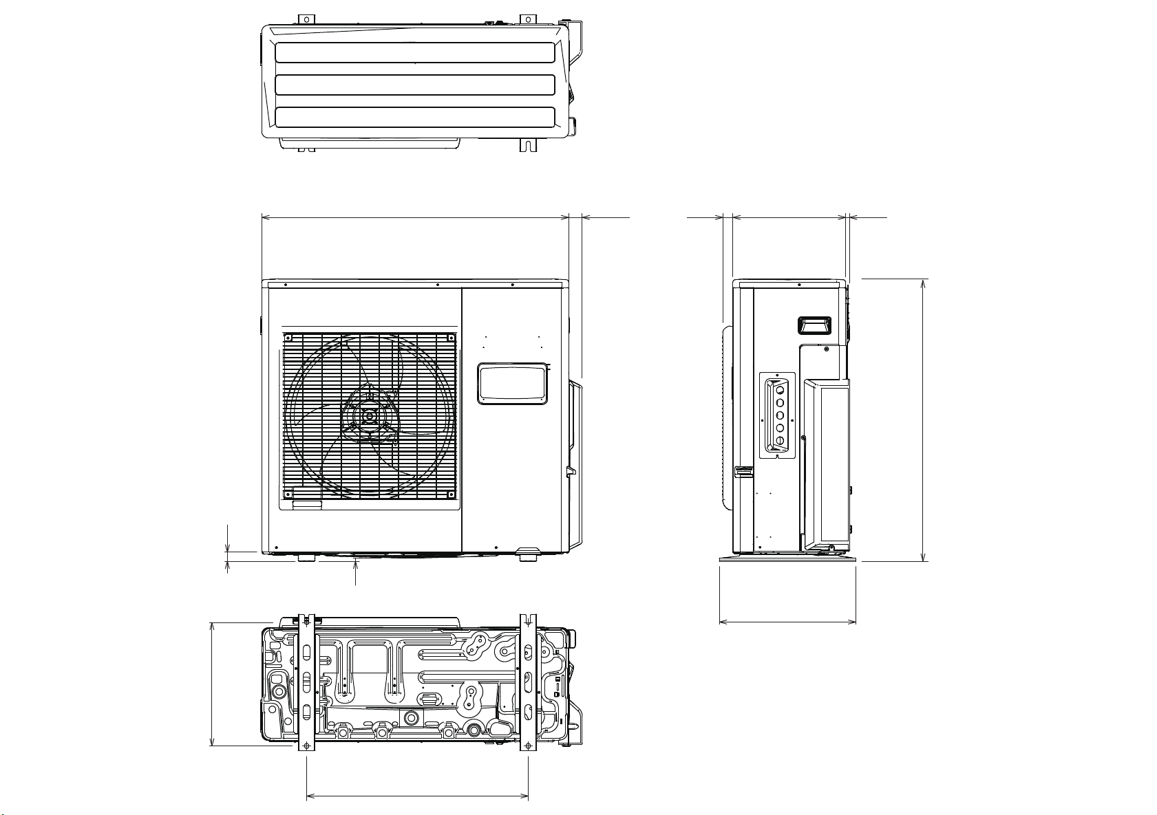
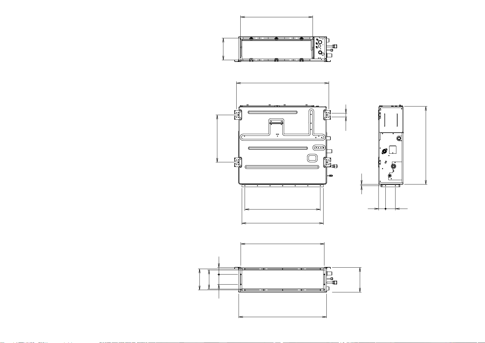
DIMENSIONS
OUTDOOR UNIT
AOU18RLXFZH
13/16 inch
21 mm
35-7/16 inch 900 mm
11/32 inch 9 mm
1-9/16 inch
40 mm
1-7/32 inch
31 mm
13 inch
330 mm
15-3/4 inch
(400 mm)
15/32 inch 12 mm
32-11/16 inch
830 mm
2015.03.02
14-9/16 inch
370 mm
25-19/32 inch 650 mm
4
Page 6
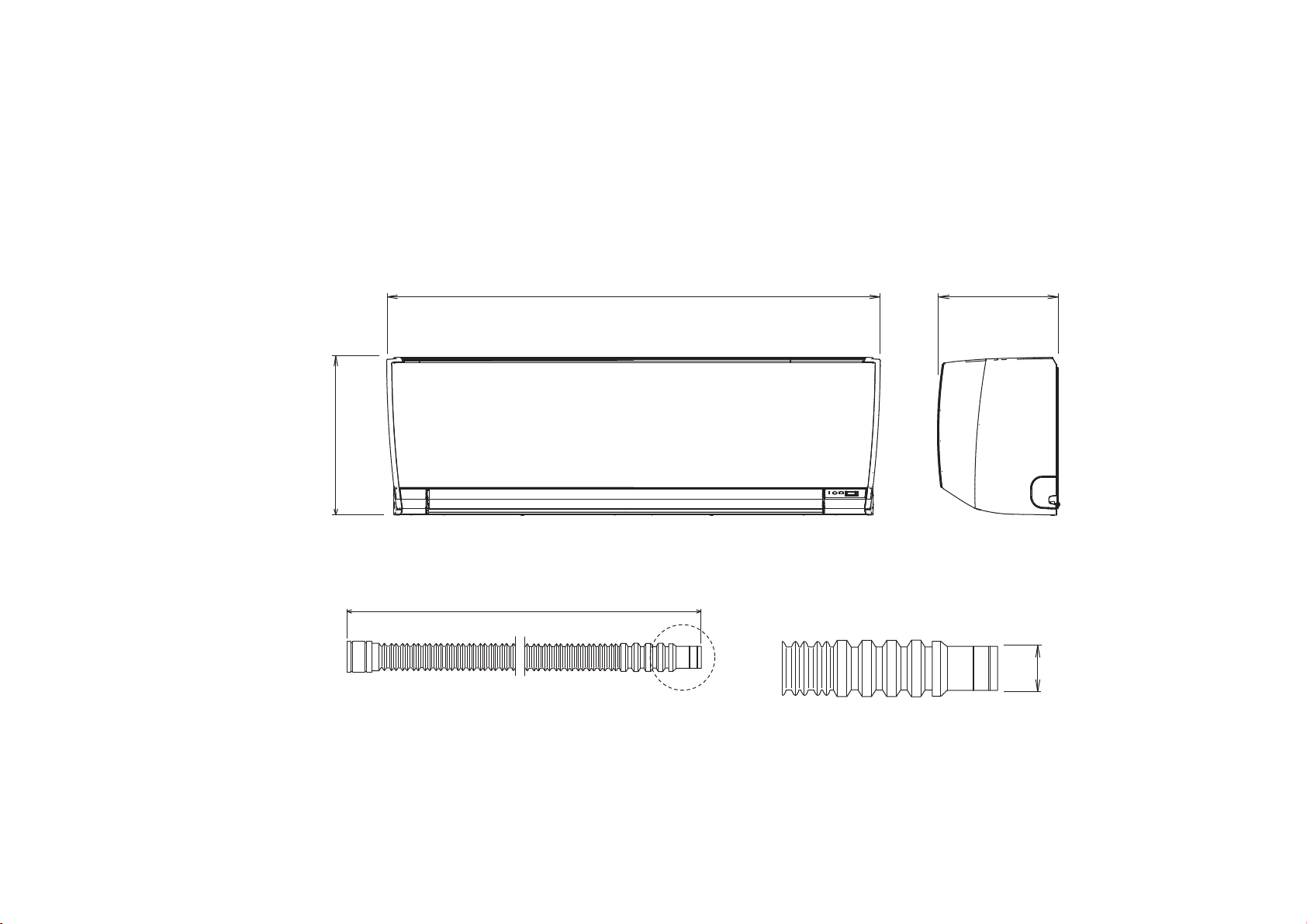
INDOOR UNIT
COMPACT WALL MOUNTED
ASU7RLF1
ASU9RLF1
ASU12RLF1
268 mm
10-9/16inch
Drain hose
33-1/16 inch 840 mm
23-5/8 inch 600 mm
8 inch
203 mm
Diameter
Outside
2015.01.19 5
15.8 to 16.7
Inside : 13.8 mm
Page 7
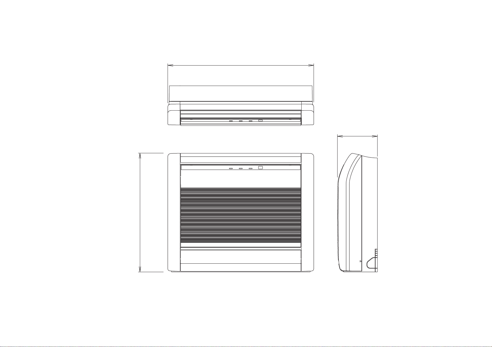
INDOOR UNIT
FLOOR
AGU9RLF
AGU12RLF
AGU15RLF
29-1/8 inch 740 mm
7-7/8 inch
200 mm
23-5/8 inch 600 mm
2014.11.30 6
Page 8
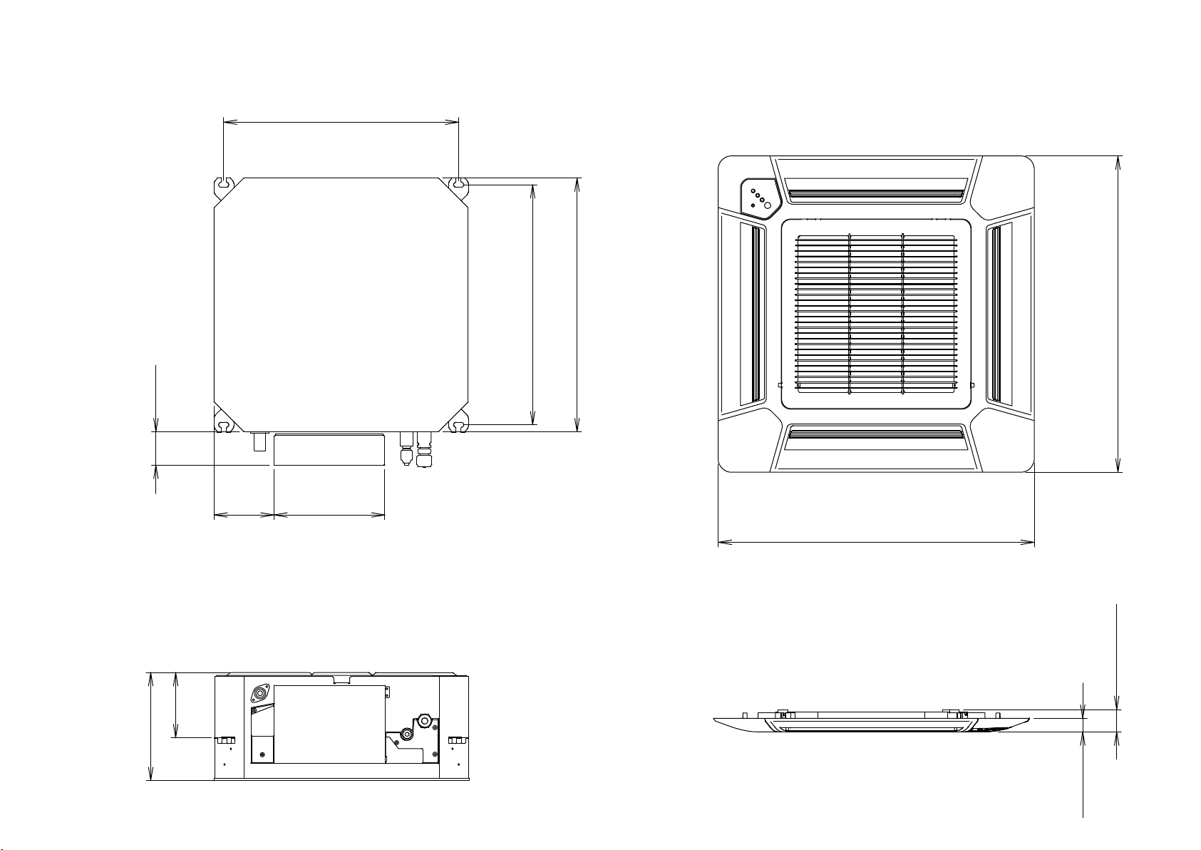
INDOOR UNIT
COMPACT CASSETTE
AUU7RLF
AUU9RLF
AUU12RLF
DECORATION PANEL
UTG-CCGF
20-7/8 inch 530 mm
2-15/16 inch
75 mm
5-3/4 inch
146 mm
245 mm
9-21/32 inch
5-5/16 inch
135 mm
9-27/32 inch
250 mm
21-1/4 inch 540 mm
Top view
Side view
22-7/16 inch 570 mm
Bottom view
Side view
27-9/16 inch 700 mm
27-9/16 inch 700 mm
1-15/16 inch
49 mm
30 mm
2015.01.19 7
1-3/16 inch
Page 9
INDOOR UNIT
SLIM DUCT (Shanghai model)
ARU7RLF
ARU9RLF
ARU12RLF
(Serial number : R)
174 mm
6-27/32 inch
377 mm
14-27/32 inch
22-19/32 inch 574 mm
28-29/32 inch 734 mm
1-3/16 inch
30 mm
2012.02.28
168 mm
6-5/8 inch
3-15/16 x 6 = 23-5/8 inch
100 mm 600 mm
25-19/32 inch 650 mm
26-5/32 inch 664 mm
2-5/32 inch 55 mm
5-15/16 inch 151 mm
78 mm
3-1/16 inch
27-9/16 inch 700 mm
8
13/32 inch 10 mm
2-5/32 inch
55 mm
198 mm
7-25/32 inch
24-13/32 inch 620 mm
3-1/16 inch
78 mm
Page 10
REFRIGERANT SYSTEM DIAGRAM
Heating Cooling
Distributor
Heat
exchanger
Heat exchanger
Strainer
Expansion
valve
OUTDOOR UNIT
Strainer
1/4”
6.35 mm
3/8”
9.52 mm
1/4”
6.35 mm
INDOOR
UNIT B
Heat
exchanger
INDOOR
UNIT A
Muffler
Compressor
4-way valve
Pressure
switch
Accumulator
Expansion
valve
92015.02.09
Strainer
Heat
exchanger
3/8”
9.52 mm
Thermistor
: Discharge pipe
: Outdoor
: Pipe
: Compressor
: Room
: Pipe
Page 11
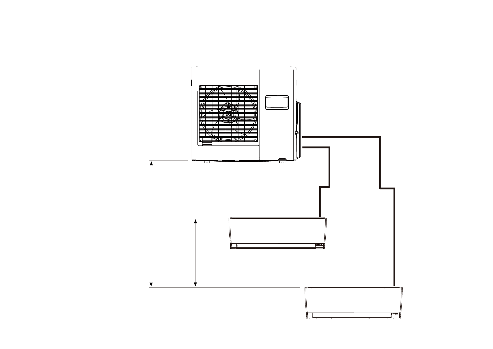
LIMITATION OF PIPING LENGTH
AND PIPING HEIGHT DIFFERENCE
Height difference between
outdoor unit and indoor unit
H1 < 49 feet
Height difference
between indoor units
H2 < 32 feet 10 inches
Sum of pipe length
49 feet < a + b < 164 feet
Pipe length between
outdoor unit an indoor unit
16 feet 5 inches < a < 82 feet
16 feet 5 inches < b < 82 feet
b
a
H1
H2
2015.02.09 10
Page 12
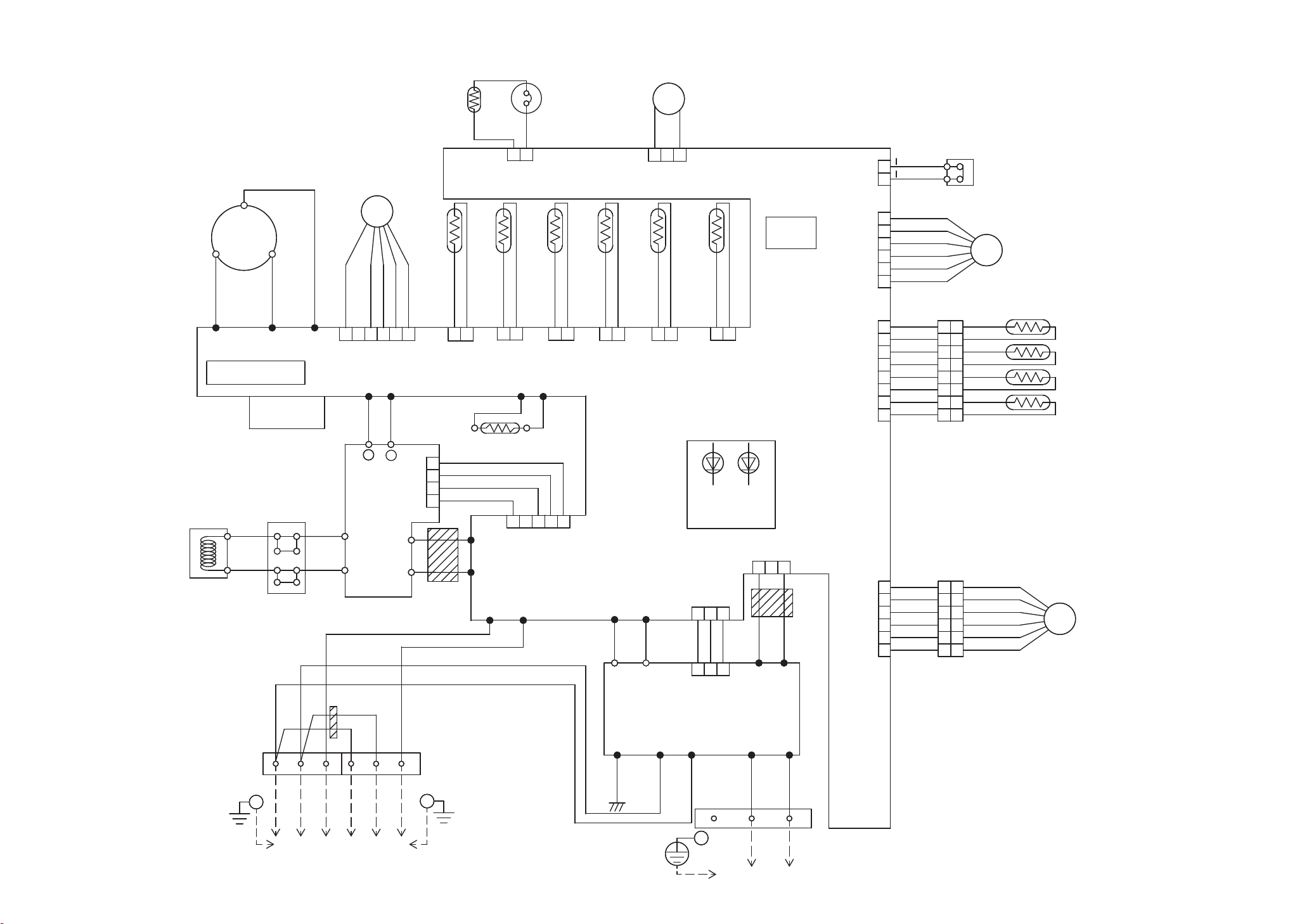
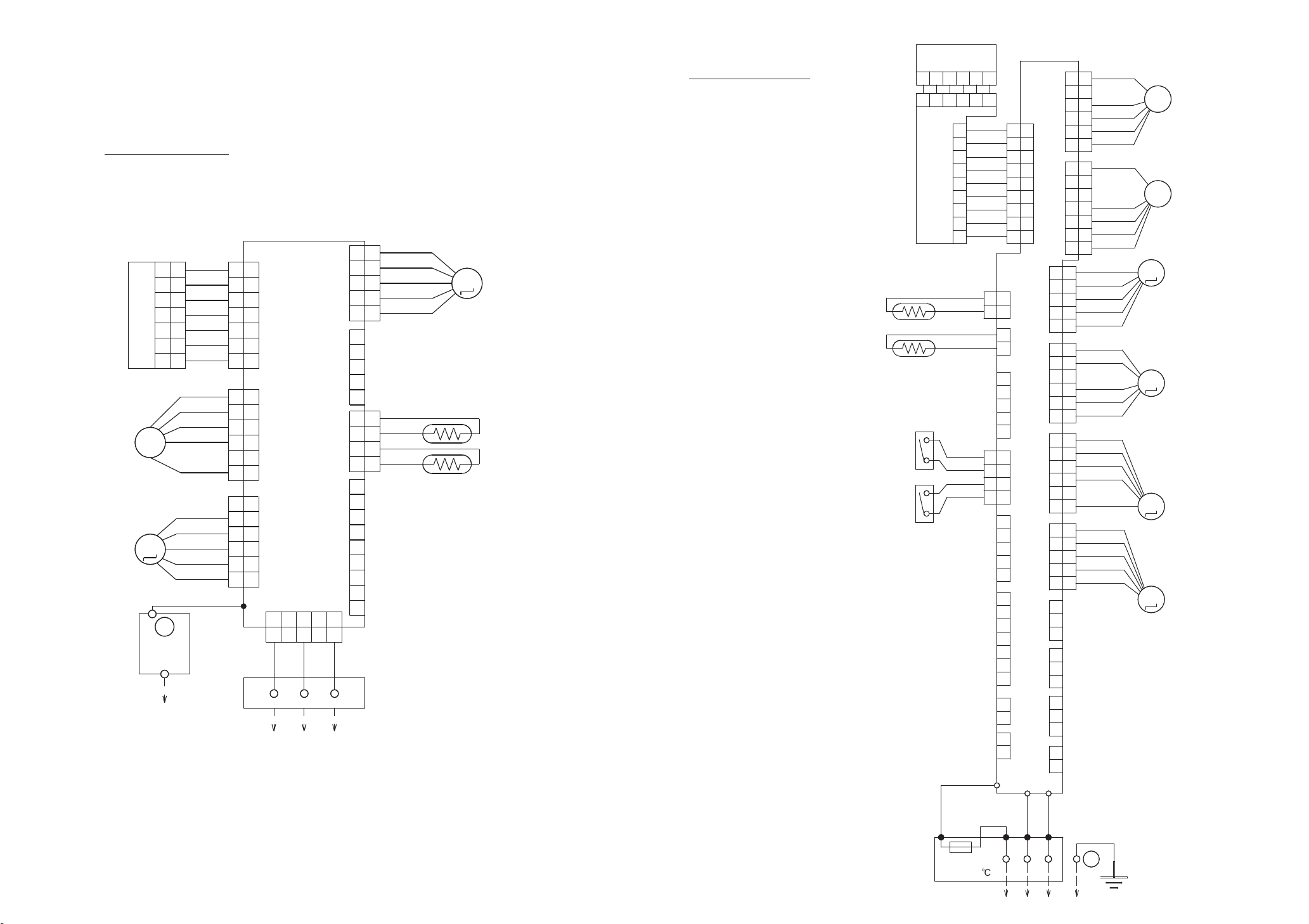
CIRCUIT DIAGRAM
OUTDOOR UNIT
AOU18RLXFZH
Heater
Thermostat
55
℃ ( °F131 )
4-Way valve coil
4WV
R
Red
U
W305
Choke
coil
T
CM
Black
Black
W304
I P M
Terminal
S
White
V
Diode
bridge
Black
W
W303
White
Brown
White
DC Fan motorCompressor
FM
Red
1 2 3 4 5 6
White
Yellow
Black
Brown
Black
Thermistor
Black
( Pipe-mid. temp. )
Thermistor
1 2
CN800
White
CN24
White
W17W16 W21W22
Orange
Black
Red
-
ACTPM
L1
L2
+
6
3
2
1
P
N1
Posistor
Yellow
Orange
Red
Brown
W12
Yellow
W13
Blue
EMI
Filter
2T
W200 W201
Red
EMI Filter
White
Black
Black
1 3
CN53
Black
Brown
Black
Black
( Heatsink temp. )
1 2
CN25
Black
Brown
Thermistor
( Comp. temp. )
Thermistor
1 2
CN26
Green
Orange
1 2 3 4 5
CN407
White
Yellow
Black
Black
3 2 1
CN30
White
Blue
Blue
( Outdoor temp. )
Black
Thermistor
Black
( Pipe temp. )
1 2 1 2
CN23
Blue
CN22
Red
Main PCB
W11 W10
Black
White
TM102
TM101
Power supply PCB
CURRENT
CHANGE
3 2 1
Brown
Thermistor
Brown
( Discharge temp. )
1 2
CN21
Yellow
LED1
LED2
D150
D151
CN34
Yellow
3 2 1
CN1
White
1 3 4
Black
Red
Brown
Black
1 2 3
CN1
White
W8
SW1
White
W9
AC IN
EMI
Filter
2T
CN37
Red
CN27
Red
CN39
White
CN50
White
1
2
1
2
3
4
5
6
1
3
4
5
6
7
8
9
1
2
4
5
6
7
Red
Red
Red
Brown
Blue
Orange
Yellow
White
Black
White
White
White
White
White
White
White
Black
White
White
White
White
White
1
2
3
4
5
6
7
8
White
1
2
3
4
5
6
White
Pressure switch SW1
Expansion valve coil A
EV
Thermistor
Red
1
Red
2
Yellow
3
Yellow
4
Blue
5
Blue
6
Black
7
Black
8
Red
1
Brown
2
Blue
3
Orange
4
Yellow
5
White
6
2-Way valve A
3-Way valve A
2-Way valve B
3-Way valve B
Expansion valve coil B
EV
W3 W7 W6 W4 W5
Terminal
132
G
132
Green
G
Unit A Unit B
2015.02.09 11
White
Black
Terminal
G
Power supply
Black
L1 L2
White
Page 13
Models : ASU7RLF1
Indicator PCB
Fan motor
Diffuser
Earth
Terminal
ASU9RLF1
ASU12RLF1
CN201
1
1
2
2
3
3
4
4
5
5
6
6
7
7
FM
M
G
White
White
White
White
White
White
White
Blue
Yellow
White
Black
RED
Red
Orange
Yellow
Pink
Blue
Green
1
1
2
2
3
3
CN3
4
4
5
5
6
6
7
7
1
1
2
2
3
3
CN7
4
4
5
5
6
6
1
1
2
2
3
3
CN5
4
4
5
5
6
6
W4
1 2 3
CN10
CN6
Main PCB
CN4
CN2
CN1
1 2 3 4 5
1 2 3 4 5
Black
White
Red
Red
1
1
Orange
2
2
Yellow
3
3
Pink
4
4
Blue
5
5
1
2
Test
3
4
5
Black
1
1
Black
2
2
Black
3
3
Black
4
4
1
2
3
4
To communication kit
5
( option )
6
7
8
9
Terminal
Louver ( up / down )M
Thermistor ( pipe temp. )
Thermistor ( room temp. )
Models : AGU9RLF
AGU12RLF
Thermistor
( pipe temp. )
Thermistor
( room temp. )
Indicator PCB
6
1 2 3 4 5 6
Switch PCB
Switch
Switch
Wired remote control
( option )
CN203
5 4 3 2 1
CN202
9
8
7
6
5
4
CN201
3
2
1
Gray
Gray
Black
Black
Test
Blue
Black
Blue
Black
Flash
Black
White
White
White
White
White
White
White
White
Red
212
4
3
2
1
Main PCB
1
1
2
2
3
3
4
4
5
5
6
6
7
7
8
8
9
9
1
CN3
2
1
5
4
3
2
1
4
3
2
CN18 CN13 CN1
1
5
4
3
2
1
7
6
5
4
3
2
1
2
1
CN22 CN9 CN6
2
1
CN21
TM5
TM1TM2
CN11
5
4
3
CN12CN8CN5
2
1
6
5
4
3
2
1
6
5
4
3
2
1
5
4
3
CN2
2
1
3
2
CN14CN15CN16CN20
1
3
2
1
3
2
1
2
1
6
6
5
5
4
4
3
3
CN10CN17
2
2
1
1
7
7
6
6
5
5
4
4
3
3
2
2
1
1
Blue
5
Pink
4
Yellow
3
Orange
2
Red
1
Blue
6
Pink
5
4
Yellow
3
Orange
2
Red
1
Blue
6
Pink
5
Yellow
4
Orange
3
2
Red
1
Blue
5
Pink
4
Yellow
3
Orange
2
Red
1
Ex. in 1
( option )
Ex. out 1
( option )
Red
Black
White
Yellow
Blue
Red
Black
White
Yellow
Blue
Fan motor
FM
( upper )
Fan motor
FM
( lower )
Damper lock
M
( left )
Damper lock
M
( right )
Louver
M
( up / down )
M
Damper
2015.01.21 12
Thermal
fuse 102
Terminal
White
1 2 3
Red
G
Page 14
Models : AUU7RLF
Louver
( Right / Left )
M
M
Louver
( Up / Down )
Fan motor
1
2
FM
3
4
5
6
7
8 8
AUU9RLF
AUU12RLF
Float switch
1
2
3
4
5
1
2
3
4
5
1
2
3
4
5
6
7
1
2
3
4
5
1
2
3
4
5
Black
Black
Orange
Yellow
Orange
Yellow
Brown
Yellow
White
Black
Red
Red
Pink
Blue
Red
Pink
Blue
1
1
CN9
2
2
3
3
1
1
2
2
CN12
3
3
4
4
5
5
1
1
2
2
3
3
CN11
4
4
5
5
1 2 3 4 5 6 7 8
1 2 3 4 5 6 7 8
Gray
Gray
1 2 3 4 5 6 7 8
1 2 3 4 5 6 7 8
1
1
2
2
3
3
CN105
4
4
5
5
6
6
E101
Green
E102
Green
Gray
Gray
Black
Black
1 2
1 2
1 2
1 2
CN5 CN8
CN13
Main PCB
CN14
CN4
CN1
1 2 3
1 2 3
Gray
Gray
Gray
Gray
Gray
Gray
Gray
1 2 3
1 2 3
CN104 CN101
Power supply PCB
CN102 CN103
1 2 3 1 2
Yellow
M
Yellow
CN6
Gray
Gray
W105
W102
W101
CN106
1 2
1 2
1
2
3
4
5
6
7
1
2
3
1
2
Brown
1
Red
2
Orange
3
Yellow
4
White
5
Blue
6
Purple
7
Red
1
White
2
Black
3
Terminal
Red
White
Black
Thermistor
( Pipe temp. )
Thermistor
( Room temp. )
1
2
3
4
5
6
7
2 3
1
Models : ARU7RLF
ARU9RLF
ARU12RLF
Black
2
2
White
1
2
3
4
5
6
1
2
3
4
5
6
7
1
1
2
2
3
3
1
2
W102
W105
W101
3
3
White
Reactor
Thermistor
( room temp. )
Red
White
Black
1
To wired remote control
Red
White
Black
1
2
1
2 3
Terminal
2 3
Terminal
G
Ground
Thermistor
( pipe temp. )
Gray Black
Gray
2
1
1
Yellow
CN1
1
1
Gray
1
1
CN101
2
2
Yellow
1
1
CN3
CN13
CN14
CN6
2
2
Gray
2
2
2
3
3
Gray
3
3
CN103
1
1
2
1
1
2
2
3
3
4
4
5
5
6
6
7
7
Indicator PCB
3
Float switch
2
1
Wired
remote
control
Terminal
G
Fan motor
FM
Black
Black
Brown
Yellow
White
Black
Red
1
2
1
CN5 CN7 CN8
1
2
3
CN12
4
5
1
2
3
CN11
4
5
1
1
CN9
2
2
3
3
1
CN10
2
1
1
2
2
3
3
CN105
4
4
5
5
6
6
E101 E102
Green
1
1
Gray
1
1
234
234
Gray
234
234
Main PCB
CN4
5 6 7
5 6 7
Gray
Gray
Gray
Gray
5 6 7
5 6 7
CN104
Power supply PCB
Green
1
8
8
Gray
Gray
8
8
CN102
2
1
2
3
CN106 CN108
M
Drain pump motor
2015.01.22 13
Drain pump motor
Page 15

O U T D O OR P C B C I R C UI T D I A G R A M
AOU18RLXFZH
3P TERMINAL
HP-T3061-3-3P
UL1015
AWG14
BLACK
L1
L2
1
2
3
1
2
3
6P TERMINAL
HP-T3036-2
UL1015
AWG14
WHITE
UL1015
AWG20
BLACK
UL1015
AWG20
WHITE
UL1015
AWG20
YELLOW
UL1015
AWG20
BLACK
UL1015
AWG20
WHITE
EMI FILTER
ZCAT1518
-0730
1T
UL1015
AWG20
RED
UL1015
AWG16
GREEN
EARTH
W4
W6
W5
W7
W3
B
B
B
B
POWER SUPPLY PCB
K04BA-1003HUE-P0
B
POWER SOURCE
AC208-230V
60Hz
INDOOR UNIT A
INDOOR UNIT B
TM100
86028
B3B-XASK-1-A
03 VH/SIN
1015 L250
CN1
WHITE
CHOKE COIL
I C404
L=0.32mH 30A
UL1015
AWG12
BLACK
TERMINAL
HP-T4005-31
UL1015
AWG14
BROWN
N1
N2
I O
1
2
3
4
5
6
EMI FILTER
GTFC-25-15-12
2T
UL1007 AWG24
UL1007 AWG24 RED
UL1007 AWG24 ORANGE
UL1007 AWG24 YELLOW
BROWN
UL1015
AWG14
YELLOW
UL1015
AWG14
BLUE
W12
B
W13
B
1
DC18V-2
3
4
5
CN407
06 PH/172520
1007 L480
WHITE
ACTPM CONTROL
W305
B
W304
B
W303
B
UL3271
AWG14
RED
U
UL3271
AWG14
WHITE
V
UL3271
AWG14
BLACK
W
COMPRESSOR
CM
Compressor
Winding Resistance
U-V
V-W
U-W
0.642
(20 68 )
F
°
UL1015
AWG12
BLACK
UL1015
AWG14
WHITE
L1 L2
+ P
PM-601BSG
TM101
UL1015
AWG14
BLACK
INVERTER ASSEMBLY
EZ-01403HUE
W10
B
W16
UL1015
AWG14
RED
B
( ACTPM )
UL1015
AWG14
WHITE
TM102
EMI FILTER
UL1015
AWG20
W9
WHITE
B
UL1015
AWG20
BLACK
W8
B
1
2
3
CT
GTFC-25-15-12
UL1007 AWG24
UL1007 AWG24
UL1007 AWG24 RED
BLACK
BROWN
2T
W11
1
3
1
3
4
B
DC5V-2DC5V
CN34
B2P3-VH-B-Y
YELLOW
AC VOLY IN
CN1
03 XA/172520
1007 L180
WHITE
CT
W17
W21
W22
UL1015
AWG14
BLACK
B
UL1015
AWG20
ORANGE
B
UL1015
AWG20
ORANGE
B
R200
ZPR0YCE400A300
-
DC FAN MOTOR
EXPANSION VALVE COIL A
FM
M
EXPANSION VALVE COIL B
M
4-WAY VALVE COIL
*DC Resistance
10%
1355
PRESSURE SWITCH
THERMISTOR ( COMPRESSOR TEMP. )
THERMISTOR ( HEATSINK TEMP. )
THERMISTOR ( DISCHARGE TEMP. )
THERMISTOR ( PIPE-OUT TEMP. )
THERMISTOR ( OUTDOOR TEMP. )
THERMISTOR
( 2-WAY VALVE A )
( 3-WAY VALVE A )
( 2-WAY VALVE B )
( 3-WAY VALVE B )
(20 68 )
°
F
UL1430 AWG22
UL1430 AWG22 BLACK
UL1430 AWG22
UL1430 AWG22 YELLOW
UL1430 AWG22 BLUE
RED
BROWN
BLUE
ORANGE
YELLOW
WHITE
UL3478 AWG20
UL3478 AWG20 BLACK
UL1430 AWG22 RED
UL1430 AWG22 RED
BLACK
BLACK
BLACK
BLACK
BLACK
BLACK
BLACK
BLACK
RED
WHITE
RED
BROWN
BLUE
ORANGE
YELLOW
WHITE
UL1430 AWG24 x 6
BLACK
WHITE
WHITE
WHITE
WHITE
WHITE
WHITE/WHITE
BLACK
BROWN
BROWN
BLACK
BLACK
BROWN
BROWN
BLACK
BLACK
BLUE
BLUE
BLACK
WHITE
WHITE
WHITE
WHITE
WHITE
WHITE
WHITE
WHITE/WHITE
UL1430 AWG24 x 8
W200 B
W201 B
DC380V-2
1
2
DC15V-4
3
4
5
6
DC12V
1
2
3
4
5
6
DC12V
1
2
4
5
6
7
CN30
179844-1
WHITE
1
AC208 - 230V
3
( ON )
1
CN37
2
B2B-XARK-1-A
RED
CN26
B2B-XAMK-1-A
1
GREEN
2
CN25
B2B-XAKK-1-A
1
BLACK
2
CN21
1
2
B2B-XH-AM
YELLOW
1
CN22
2
B2B-XH-AM
RED
1
2
CN23
B2B-XAEK-1-A
1
BLUE
CN39
4
5
08 XA/172520
6
7
1430
8
WHITE
9
SERIAL A
SERIAL B
CN800
B6P-VH-B
WHITE
CN27
B6B-XARK-1-A
RED
CN50
06 XA/172520
1430
WHITE
CN26
Thermistor Characteristics.
Thermistor
Temperature
Thermistor ( Compressor temp. )
CN25
Thermistor Characteristics.
Thermistor
Temperature
Thermistor ( Heatsink temp. )
CN21
Thermistor Characteristics.
Thermistor
Temperature
Thermistor ( Discharge temp. )
CN23
Thermistor Characteristics.
Thermistor
Temperature
Thermistor ( Outdoor temp. )
CN800 DC Fan motor
Pin No.
1
Terminal
code
Vm
Function of terminal
Motor power voltage input
2
3
GND
4
Vcc
Vsp
5
6
FG
CN27,50 Expansion valve coil
Recommended drive condition
unipolar draive, 1-2 phase excitation.
GND
Control power voltage input
Speed control voltage input
Revolution pulse output
1(Red) - 3(Blue)
1(Red) - 4(Orange)
Coil resistance
1(Red) - 5(Yellow)
1(Red) - 6(White)
2(Brown) - 3(Blue)
(20 68 )
2(Brown) - 4(Orange)
2(Brown) - 5(Yellow)
2(Brown) - 6(White)
F
( 0 32 )
168.6 k
0.4 V
( 0 32 )
16.1 k
0.9 V
( 0 32 )
167.1 k
0.4 V
( 0 32 )
54.0 k
2.1 V
°
F
°
F
°
F
°
F
(20 68 )
°
62.6 k
0.9 V 1.2 V
F
(20 68 )
°
6.1 k
1.9 V 2.5 V
F
(20 68 )
°
62.1 k 39.8 k
0.9 V 1.2 V
F
(20 68 )
°
20.1 k
3.3 V 3.7 V
46.0
F
°
(30 86 )
40.0 k
(30 86 )
3.9 k
(30 86 )
(30 86 )
12.9 k
Lead wire
color
Red
Black
White
Yellow
Brown
CN39
Thermistor Characteristics.
F
°
Thermistor
Thermistor ( Valve A,B temp. )
F
°
F
°
F
°
CN53
B4P-VH-B-C
BLACK
CN24
CN24
B2B-XH-AM
B2B-XH-AM
WHITE
WHITE
MAIN PCB
K14WH-1400HUE-C1
1
2
3
4
1
1
2
2
Temperature
( 0 32 )
176.0 k
1.1 V
WHITE
BLACK
UL1015 AWG22 x 2
BLACK
BLACK
BLACK
BLACK
F
(20 68 )
°
62.9 k
2.2 V 2.8 V
F
°
(30 86 )
F
°
39.6 k
BASE HEATER
THERMISTOR ( PIPE - MID. TEMP. )
THERMISTOR ( PIPE - MID. TEMP. )
CN22, 24
Thermistor Characteristics.
Thermistor
Thermistor ( Pipe-out temp. )
Thermistor ( Pipe-mid temp. )
Temperature
( 0 32 )
°
16.1 k
1.1 V
F
(20 68 )
6.0 k
2.2 V 2.8 V
F
°
(30 86 )
°
3.8 k
DC5V
1
DC5V
2
3
4
5
6
1
2
3
4
5
6
CN55
B06B-PASK-1
WHITE
INV-FLASH
CN54
B06B-PASK-1
WHITE
MAIN-FLASH
F
2015.07.08 14
Page 16

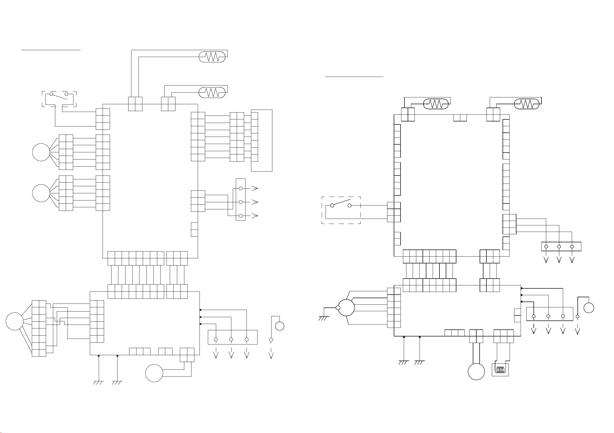
EARTH TERMINAL
I N D O O R PC B
C I RCU IT D IA GR A M
CN7 DC Fan motor
Pin No.
6
5
4
3
2
1
Terminal
code
Vm
Motor power voltage input
GND
Vcc
Control power voltage input
Vsp
Speed control voltage input
Revolution pulse output
PG
Function of terminal
GND
Lead wire
color
Red
Black
White
Yellow
Blue
DC FAN MOTOR
DIFFUSER
OUTDOOR UNIT
F M
M
BLACK
WHITE
YELLOW
BLUE
BLUE
PINK
YELLOW
ORANGE
CONTROL UNIT
ASU7RLF1 : EZ-0131DHSE
ASU9RLF1 : EZ-0130WHSE
ASU12RLF1 : EZ-0130YHSE
3
2
1
WHITE
TERMINAL
BLACK
1 2 3 4
SC25-05WSA
RED
6
DC340V
5
4
DC15V
3
2
1
CN7
B5 ( 6-5 ) B-XARK-1-A
RED
RED
5
CN1
WHITE
CN4
B4B-PH-K-S
WHITE
DC15V
CN10
B5B-PH-K-S
WHITE
GREEN
W4
1
2
3
4
1
2
3
4
5
BLACK
BLACK
BLACK
BLACK
RED
ORANGE
YELLOW
PINK
BLUE
MAIN PCB
ASU7RLF1 : K12JY-1402HSE-C1
ASU9RLF1
ASU12RLF1
CN5
6
B6B-PH-K-S
WHITE
5
4
DC15V
RED
3
2
1
: K12JY-1400HSE-C1
: K12JY-1401HSE-C1
DC5V
CN3
B7B-PH-K-FN
NATURAL
1
2
3
4
5
6
7
WHITE
WHITE
WHITE
WHITE
WHITE
WHITE
WHITE
CN4 Thermistor Characteristics.
Thermistor
Temperature
Thermistor ( Pipe temp. )
Thermistor ( room temp. )
THERMISTOR ( PIPE TEMP. )
THERMISTOR ( ROOM TEMP. )
M
1
2
3
4
5
6
7
LOUVER ( UP / DOWN )
I NDICATOR PCB
K12JZ-1200HSE-D0
CN201
S7B-PH-K-S
( 0 32 )
°
176.0 k
1.1 V
33.6 k
1.1 V
F
(20 68 )
62.9 k
2.2 V 2.8 V
12.5 k
2.2 V 2.8 V
F
(30 86 )
°
39.6 k
8.0 k
F
°
COMMUNICATION KIT
( OPTION )
2015.08.21 15
CN2
B7 ( 9-7.8 ) B-PL I SK
9pin
DC340V
9
6
5
4
3
2
1
CN6
B5B-PH-K-S
DC5V
1
RED
2
3
4
5
TEST
Page 17

CONTROL UNIT
AGU9RLF : EZ-01302HSE
AGU12RLF : EZ-01303HSE
I NDICATOR PCB ( SWITCH + DISPLAY )
K06DD-0801HSE-F0
CN17 DC Fan motor ( Lower )
Pin No.
7
Terminal
code
Function of terminal
Vm
Motor power voltage input
6
5
4
GND
3
Vcc
Vsp
2
1
PG
GND
Control power voltage input
Speed control voltage input
Revolution pulse output
CN10 DC Fan motor ( Upper )
Pin No.
6
Terminal
code
Function of terminal
Vm
Motor power voltage input
5
4
GND
3
Vcc
Vsp
2
1
PG
GND
Control power voltage input
Speed control voltage input
Revolution pulse output
DC FAN MOTOR
( LOWER )
DC FAN MOTOR
( UPPER )
POWER SOURCE
AC208-230V
60Hz
Lead wire
color
Red
Black
White
Yellow
Blue
Lead wire
color
Red
Black
White
Yellow
Blue
SERIAL
F M
F M
L
N
HP-T3064A-A28-L1
THERMAL
FUSE 102
3A 250V
1
2
3
TERMINAL
WIRED REMOTE CONTROL
( OPTION )
DAMPER
LOUVER
( UP / DOWN )
DAMPER LOCK
( RIGHT )
DAMPER LOCK
( LEFT )
L I N
TM5
22007
BLACK
WHITE
RED
BLACK
N I N
TM1
22007
WHITE
SERIAL I N
TM2
22007
RED
CN6
B05B-XASK-1-A
WHITE
B09B-PAEK-1
B05B-PH-K-S
DC12V
CN8-1
RED
CN8-2 WHITE
CN8-3
BLACK
CN2-1
RED
CN2-2
ORANGE
M
M
M
CN2-3 YELLOW
CN2-4
PINK
CN2-5 BLUE
CN5-1
RED
CN5-2 ORANGE
CN5-3 YELLOW
CN5-4
PINK
CN5-5
BLUE
CN8-1
RED
CN8-2 ORANGE
CN8-3 YELLOW
CN8-4 PINK
CN8-5 BLUE
1
2
3
4
5
DC12V
1
2
CN2
3
SJH20-05WS
WHITE
4
5
DC12V
1
2
CN5
3
SJH20-06WS
4
WHITE
5
6
DC12V
1
2
CN8
3
B06B-PASK-1
4
WHITE
5
6
B04B-PASK-1
MAIN PCB
AGU9RLF : K09DD-1400HSE-C1
AGU12RLF : K09DD-1401HSE-C1
B3B-XH-AM
B3B-XH-AM-BK
B3B-XH-AM-R
B2B-XH-AM
CN11
BLUE
DC5V
CN13
WHITE
DC5V
CN18
WHITE
CN14
WHITE
CN15
BLACK
CN16
CN20
WHITE
9
8
7
6
5
4
3
2
1
1
2
3
4
5
1
2
3
4
1
2
3
1
2
3
1
2
RED
3
1
2
DC12V
CN12-1
RED
CN12-2
ORANGE
M
CN12-3 YELLOW
CN12-4 PINK
CN12-5 BLUE
CN17-7 RED
CN17-4 BLACK
CN17-3 WHITE
CN17-2 YELLOW
CN17-1 BLUE
CN10-6 RED
CN10-4 BLACK
CN10-3 WHITE
CN10-2 YELLOW
CN10-1 BLUE
1
2
CN12
3
B05B-PASK-1
WHITE
4
5
CN17
B5 ( 7-5.6 ) B-XASK-1-A
WHITE
DC340V
7
6
5
DC15V
4
3
2
1
CN10
B5 ( 6-5 ) B-XARK-1-A
RED
DC340V
6
5
DC15V
4
3
2
1
CN21
B2B-XH-AM-BK
BLACK
CN22
B2B-XH-AM-R
DC5V
CN9
B07B-PASK-1
WHITE
CN3
B02B-PASK-1
WHITE
CN1
2P-SAN
WHITE
1
2
1
2
RED
1
2
3
4
5
6
7
1
2
1
2
CN11-9
RED
CN11-8
WHITE
CN11-7
WHITE
CN11-6
WHITE
CN11-5
WHITE
CN11-4
WHITE
CN11-3
WHITE
CN11-2
WHITE
CN11-1 WHITE
TEST
DAMPER LIMIT SWITCH
( CLOSE )
CN18-1 BLACK
CN18-2 BLUE
CN18-3 BLACK
CN18-4
BLUE
DAMPER LIMIT SWITCH
( OPEN )
EX I N - 1
EX I N - 2
EX I N - 3
EX OUT - 1
EX OUT - 2
EX OUT - 3
CN13-1
CN13-2
CN13-3
CN13-4
FLASH
CN13-5
CN13-6
CN13-7
THERMISTOR ( PIPE TEMP. )
CN3-1
GRAY
CN3-2
GRAY
THERMISTOR ( ROOM TEMP. )
CN2-1 BLACK
CN2-2
BLACK
1
2
3
4
CN201
5
JB20-09HG
6
7
DC5V
8
9
DC5V
WHITE
CN201-1 WHITE
CN201-2
DISPLAY PCB
CN3
Thermistor Characteristics.
Thermistor
Thermistor ( Pipe temp. )
CN1
Thermistor Characteristics.
Thermistor
Thermistor ( Room temp. )
CN202
JB20-06HG
4321
5
WHITE
WHITE
CN201-3
CN201-5
CN201-4 WHITE
3456
2
DC5V
Temperature
Temperature
6
WHITE
CN201-6
1
CN203
JB20-06HG
( 0 32 )
°
176.0 k
1.1 V
( 0 32 )
°
33.6 k
1.1 V
F
(20 68 )
62.9 k
2.2 V 2.8 V
F
(20 68 )
12.5 k
2.2 V 2.8 V
F
°
F
°
(30 86 )
°
39.6 k
(30 86 )
°
8.0 k
F
F
SWITCH PCB
2015.08.21 16
Page 18

POWER SOURCE
AC208 - 230V
60Hz
SERIAL
HP-T3031-3-L1
L
N
E
TERMINAL
1
2
3
CONTROL UNIT
AUU7RLF : EZ-0131CHSE
AUU9RLF
AUU12RLF
: EZ-0100HSE
: EZ-0105HSE
UL1015
AWG20
WHITE
W102 W101
W105
UL1015
AWG20
RED
UL1015
AWG20
BLACK
B02B-XASK-1-A
B02B-XAYK-1-A
CN2-1
CN2-2
CN2-3
CN2-4
CN2-5
CN2
B5P-SHF-1AA
WHITE
B02B-XAKK-1-A
DC5V
CN15-1
CN15-2
CN15
CN15-3
CN15-4
B06B-XASK-1-A
CN15-5
WHITE
CN15-6
MAIN PCB
AUU7RLF : K06AK-1400HSE-C1
AUU9RLF : K06AK-1401HSE-C1
AUU12RLF : K06AK-1402HSE-C1
CN8
WHITE
CN7
YELLOW
CN5
BLACK
CN13
B07B-PASK-1
WHITE
DC5V
CN8-1
CN8-2
CN7-1
CN7-2
CN5-1
CN5-2
CN13-1
CN13-2
CN13-3
CN13-4
CN13-5
CN13-6
CN13-7
BLACK
BLACK
GRAY
GRAY
JUNCTION
CONNECTOR
XMR-07V
WHITE
BROWN
RED
ORANGE
YELLOW
GREEN
BLUE
PURPLE
UL1430 AWG28
x 7
CN8
Thermistor Characteristics.
Thermistor
Temperature
Thermistor ( Room temp. )
CN5
Thermistor Characteristics.
Thermistor
Temperature
Thermistor ( Pipe temp. )
( 0 32 )
33.6 k
1.1 V
( 0 32 )
168.6 k
1.1 V
THERMISTOR ( ROOM TEMP. )
THERMISTOR ( PIPE - MID. TEMP. )
DECORATION PANEL ASSEMBLY ( OPTION )
I NDICATOR PCB
K06AG-1000HSE-D0
1
2
3
4
5
6
7
UL1430 AWG28
1
2
3
4
5
6
7
BROWN
RED
ORANGE
YELLOW
GREEN
BLUE
PURPLE
x 7
CN201-1
CN201-2
CN201-3
CN201-4
CN201-5
CN201-6
CN201-7
CN201
S07B-PASK-2
WHITE
F
(20 68 )
°
12.5 k
2.2 V 2.8 V
F
(20 68 )
°
62.5 k
2.2 V 2.8 V
F
°
F
°
(30 86 )
°
8.0 k
(30 86 )
°
40.0 k
F
F
CN105 DC Fan motor
Terminal
Pin No.
code
6
Vm
5
4
GND
3
Vcc
Vsp
2
1
PG
Function of terminal
Motor power voltage input
GND
Control power voltage input
Speed control voltage input
Revolution pulse output
DC FAN MOTOR
Lead wire
color
Red
Black
White
Yellow
Blue
DRAIN PUMP
F M
M
EMI FILTER
ZCAT2132-1130
1 TURN
1
2
3
4
5
6
7
8
UL1015 AWG18
UL1015 AWG18 BLACK
EX OUT
UL1015
AWG16
GREEN
UL1015
AWG16
GREEN
EX I N
RED
BLACK
WHITE
YELLOW
BROWN
BLACK
E101
E102
CN105-6
CN105-5
CN105-4
CN105-3
CN105-2
CN105-1
CN106-1
CN106-2
CN103-1
CN103-2
CN102-1
CN102-2
CN102-3
DC340V
POWER SUPPLY PCB
K06AL-1005HSE-P0
DC15V
CN105
B5P6-VH-B
WHITE
CN106
B2P3-VH-B-E
BLUE
CN103
B2B-XH-AM
WHITE
CN103
B3B-XH-AM
WHITE
CN104
B08B-PASK-1
WHITE
CN101
B03B-PASK-1
WHITE
DC13.5V
DC5V
CN104-1
CN104-2
CN104-3
CN104-4
CN104-5
CN104-6
CN104-7
CN104-8
CN101-1
CN101-2
CN101-3
POWER DRIVE
UL1430 AWG26 x 8
DC SUPPLY
UL1430 AWG26 x 3
GRAY
GRAY
GRAY
GRAY
GRAY
GRAY
GRAY
GRAY
GRAY
GRAY
GRAY
CN3-1
CN3-2
CN3-3
CN3-4
CN3-5
CN3-6
CN4-1
CN4-2
CN4-3
CN4-4
CN4-5
CN4-6
CN4-7
CN4-8
CN1-1
CN1-2
CN1-3
DC13.5V
CN3
B06B-PASK-1
WHITE
CN4
B08B-PASK-1
WHITE
CN1
B03B-PASK-1
WHITE
DC13.5V
DC5V
DC12V
CN14
B03B-XAKK-1-A
BLACK
DC13.5V
B02B-PAMK-1-A
CN6
GREEN
DC13.5V
CN10
B02B-PAOK-1
ORANGE
DC13.5V
CN11
B05B-XASK-1-A
WHITE
DC13.5V
CN12
B05B-XARK-1-A
CN9
B03B-XARK-1-A
CN14-1
CN14-2
CN14-3
EMI FILTER
ZCAT1518-0730
1 TURN
CN6-1
CN6-2
CN10-1
CN10-2
CN11-1
CN11-2
CN11-3
CN11-4
CN11-5
CN12-1
CN12-2
CN12-3
CN12-4
CN12-5
RED
RED
ORANGE
YELLOW
PINK
BLUE
UL1430 AWG26 x 5
UL1430 AWG22
UL1430 AWG22 WHITE
UL1430 AWG22 BLACK
FRESH AIR
( OPTION )
HEATER
( OPTION )
RED
ORANGE
YELLOW
PINK
BLUE
RED
TERMINAL BOARD
HP-T3031-21
LOUVER ( UP / DOWN )
M
( OPTION )
BLK WHT
RED
WIRED REMOTE CONTROL
FLOAT SWITCH
CN9-1
CN9-2
CN9-3
RED
UL1007 AWG24 BLACK
UL1007 AWG24
BLACK
2015.08.21 17
Page 19

CN105 DC Fan motor
Terminal
Pin No.
code
6
Vm
Motor power voltage input
5
4
GND
3
Vcc
Control power voltage input
Vsp
2
1
Speed control voltage input
Revolution pulse output
PG
Function of terminal
GND
POWER SOURCE
AC208 - 230V
60Hz
Lead wire
color
Red
Black
White
Yellow
Blue
DC FAN MOTOR
DRAIN PUMP
F M
M
REACTOR ASSY
RLEY41-22
22mH, 2.2A
L
N
SERIAL
E
EMI FILTER
ZCAT2132-1130
1 TURN
1
2
3
4
5
6
7
8
UL1015 AWG18
UL1015 AWG18
EX OUT
TERMINAL
HP-T3031-3-L1
1
2
3
UL1015
AWG16
GREEN
UL1015
AWG16
GREEN
RED
BLACK
WHITE
YELLOW
BROWN
BLACK
BLACK
EX I N
WHITE
WHITE
CONTROL UNIT
ARU7RLF : EZ-0131BHSE
ARU9RLF
ARU12RLF
E101
E102
DC340V
CN105-6
CN105-5
CN105-4
CN105-3
CN105-2
CN105-1
CN106-1
CN106-2
CN103-1
CN103-2
CN102-1
CN102-2
CN102-3
CN108-1
CN108-2
CN108-3
DC15V
CN105
B5P6-VH-B
WHITE
CN106
B2P3-VH-B-E
BLUE
CN103
B2B-XH-AM
WHITE
CN103
B3B-XH-AM
WHITE
CN108
B2P3-VH-B
WHITE
: EZ-01123HSE
: EZ-01124HSE
UL1015
AWG20
RED
W105
POWER SUPPLY PCB
K06AL-1006HSE-P0
UL1015
AWG20
WHITE
W102 W101
UL1015
AWG20
BLACK
CN104
B08B-PASK-1
WHITE
CN101
B03B-PASK-1
WHITE
DC5V
DC13.5V
CN104-1
CN104-2
CN104-3
CN104-4
CN104-5
CN104-6
CN104-7
CN104-8
CN101-1
CN101-2
CN101-3
POWER DRIVE
UL1430 AWG26 x 8
DC SUPPLY
UL1430 AWG26 x 3
GRAY
GRAY
GRAY
GRAY
GRAY
GRAY
GRAY
GRAY
GRAY
GRAY
GRAY
CN2-1
CN2-2
CN2
CN2-3
B5P-SHF-1AA
CN2-4
WHITE
CN2-5
DC5V
CN15-1
CN15-2
CN15
CN15-3
CN15-4
B06B-XASK-1-A
CN15-5
WHITE
CN15-6
MAIN PCB
ARU7RLF : K06AK-1404HSE-C1
ARU9RLF : K06AK-1405HSE-C1
ARU12RLF : K06AK-1406HSE-C1
DC13.5V
CN3-1
CN3-2
CN3
CN3-3
CN3-4
B06B-PASK-1
CN3-5
WHITE
CN3-6
CN4-1
CN4-2
CN4-3
CN4
CN4-4
B08B-PASK-1
CN4-5
WHITE
CN4-6
CN4-7
CN4-8
CN1
B03B-PASK-1
WHITE
DC13.5V
CN1-1
CN1-2
CN1-3
DC5V
CN8
B02B-XASK-1-A
WHITE
CN7
B02B-XAYK-1-A
YELLOW
CN5
B02B-XAKK-1-A
BLACK
CN13
B07B-PASK-1
WHITE
DC12V
CN14
B03B-XAKK-1-A
BLACK
DC13.5V
CN6
B02B-PAMK-1-A
GREEN
DC13.5V
CN10
B02B-PAOK-1
ORANGE
DC13.5V
CN11
B05B-XASK-1-A
WHITE
DC13.5V
CN12
B05B-XARK-1-A
B03B-XARK-1-A
RED
CN9
RED
DC5V
CN8-1
CN8-2
CN7-1
CN7-2
CN5-1
CN5-2
CN13-1
CN13-2
CN13-3
CN13-4
CN13-5
CN13-6
CN13-7
CN14-1
CN14-2
CN14-3
CN6-1
CN6-2
CN10-1
CN10-2
CN11-1
CN11-2
CN11-3
CN11-4
CN11-5
CN12-1
CN12-2
CN12-3
CN12-4
CN12-5
CN9-1
CN9-2
CN9-3
BLACK
BLACK
GRAY
GRAY
BROWN
1
RED
2
ORANGE
3
WHITE
4
5
BLUE
6
PURPLE
7
GRAY
UL1430 AWG28 x 7
8
JUNCTION
CONNECTOR
XMR-08V
WHITE
EMI FILTER
ZCAT1518-0730
1 TURN
RED
ORANGE
YELLOW
PINK
BLUE
UL1430 AWG26 x 5
UL1007 AWG24 BLACK
UL1007 AWG24 BLACK
CN8
Thermistor Characteristics.
Thermistor
Thermistor ( Room temp. )
CN5
Thermistor Characteristics.
Thermistor
Thermistor ( Pipe temp. )
THERMISTOR ( ROOM TEMP. )
THERMISTOR ( PIPE - MID. TEMP. )
RECEIVER UNIT ( OPTION )
JUNCTION
CONNECTOR
XMR-08V
WHITE
1
1
2
2
3
3
4
4
5
5
6
6
7
7
8
8
UL1430 AWG28 x 7
1
2
3
4
5
6
7
8
RED
ORANGE
YELLOW
PINK
BLUE
BROWN
RED
ORANGE
WHITE
BLUE
PURPLE
GRAY
UL1430 AWG22 RED
UL1430 AWG22 WHITE
UL1430 AWG22 BLACK
FRESH AIR
( OPTION )
HEATER
( OPTION )
FLOAT SWITCH
INDICATOR PCB
K04EI-1000HSE-D0
CN201-1
CN201-2
CN201-3
CN201-4
CN201-5
CN201-6
CN201-7
CN201
S07B-PASK-2
WHITE
TERMINAL BOARD
HP-T3031-21
LOUVER ( UP / DOWN )
M
( OPTION )
Temperature
( 0 32 )
°
F
33.6 k
1.1 V
Temperature
( 0 32 )
°
F
168.6 k
1.1 V
BLK WHT
RED
WIRED REMOTE CONTROL
F
(20 68 )
°
12.5 k
2.2 V 2.8 V
F
(20 68 )
°
62.5 k
2.2 V 2.8 V
(30 86 )
°
8.0 k
(30 86 )
°
40.0 k
F
F
2015.08.21 18
Page 20

ERROR DETECTION
OUTDOOR UNIT
AOU18RLXFZH
Error contents
: Flashing
: Off
LED 1 LED 2
Discharge temp. sensor error
Outdoor unit heat ex. middle temp. sensor error
Outdoor temp. sensor error
2-way valve temp. sensor error (for IU A)
2-way valve temp. sensor error (for IU B)
3-way valve temp. sensor error (for IU A)
3-way valve temp. sensor error (for IU B)
Compressor temp. sensor error
Heat sink temp. sensor error
High pressure switch 1 error
High pressure switch 2 error
Indoor unit capacity error
Trip detection
Compressor rotor position detection error
2 times
3 times
4 times
5 times
5 times
6 times
6 times
7 times
8 times
9 times
10 times
11 times
12 times
13 times
LED4
LED3
LED2
LED1
LED is on a reverse
side of the board.
Hole
Trip terminal L error
Outdoor unit fan motor error
Outdoor unit PCB microcomputer communication error
Discharge temperature error
Compressor temperature error
4-way valve error
Outdoor unit PCB model information error
Active filter error, PFC circuit error
192015.01.22
14 times
15 times
17 times
18 times
19 times
20 times
21 times
22 times
Page 21

INDOOR UNIT
and WIRED REMOTE CONTROL
If you use a wireless remote control, the lamp
on the photo detector unit will output error codes
by way of blinking patterns.
If you use a wired type remote control, error
codes will appear on the remote control display.
See the lamp blinking patterns and error codes
in the table. An error display is displayed only
during running.
This is possible only on a wired remote control.
If an error occurs, the following display will be shown.
(“Er” will appear in the set room temperature display.)
Error code
EX. Self-diagnosis
: 0.5s on / 0.5s off
: 0.1s on / 0.1s off
( ) : Number of flashing
OPERATION
lamp
(green)
(1) (1)
(1) (2)
(1)
(2)
(2) (2)
(2) (3)
(2)
(2)
(3)
(3) (5)
(4) (1)
(4) (2)
(5)
(5)
(5) (7)
(5) (15)
(6)
(6) (3)
(6)
(6) (5)
Indoor unit
TIMER
lamp
(orange)
(5)
(1)
(4)
(7)
(2)
(1)
(3)
(2)
(4)
ECONOMY
lamp
(green)
Wired
remote
control
Description
Serial communication error
Wired remote control
communication error
Check run unfinished
Unit number or Refrigerant circuit
address setting error
[Simultaneous Multi]
Indoor unit capacity error
Combination error
Connection unit number•
error (indoor slave unit)
[Simultaneous Multi]
Connection unit number error
•
(indoor unit or branch unit)
[Flexible Multi]
Primary unit, secondary unit setup
error [Simultaneous Multi]
Indoor unit PCB model
information error
Manual auto switch error
Inlet air temp. sensor error
Indoor unit Heat Ex. Middle
temp. sensor error
Indoor unit fan motor error
Drain pump error
Damper error
Indoor unit error
Outdoor unit main PCB model
information error or
communication error
Inverter error
Active filter error, PFC circuit error
Trip terminal L error
OPERATION
lamp
(green)
(6)
(7)
(7) (2)
(7) (3)
(7) (4)
(7)
(7) (6)
(7) (7)
(8) (2)
(8) (3)
(8) (4)
(8) (6)
(9) (4)
(9) (5)
(9) (7)
(9) (9)
(10) (1)
(10) (3)
(10) (4)
(10) (5)
(13) (2)
Indoor unit
TIMER
lamp
(orange)
(10)
(1)
(5)
ECONOMY
lamp
(green)
Wired
remote
control
Description
Display PCB microcomputers
communication error
Discharge temp. sensor error
Compressor temp. sensor error
Outdoor unit Heat Ex. liquid
temp. sensor error
Outdoor temp. sensor error
Suction Gas temp. sensor error
2-way valve temp. sensor error
•
3-way valve temp. sensor error
•
Heat sink temp. sensor error
Sub-cool Heat Ex. gas inlet•
temp. sensor error
Sub-cool Heat Ex. gas outlet
•
temp. sensor error
Liquid pipe temp. sensor error
Current sensor error
Discharge pressure sensor error•
Suction pressure sensor error•
High pressure switch error•
Trip detection
Compressor rotor position
detection error (permanent stop)
Outdoor unit fan motor error
4-way valve error
Discharge temp. error
Compressor temp. error
High pressure error
Low pressure error
Branch boxes error
[Flexible Multi]
2011.02.10 20
Page 22

PARTS
OUTDOOR UNIT
AOU18RLXFZH
6
3
4
2
Ref. Description Part number
5
1
8
7
212015.01.16
1 Protective Net
2 Thermo Holder
3 Top Panel Sub Assy
4 Front Panel Sub Assy
5 Rear Emblem
6 Service Panel Sub Assy
7 Right Panel Sub Assy
8 Valve Cover Sub Assy
9375381011
9375211011
9374417025
9374414079
9351355005
9374415038
9374416097
9374827015
Page 23

Ref. Description Part number
11 Propeller fan
12 Fan Motor
13 Heater Unit Assy
14 Outdoor Thermistor
15 Compressor Thermistor
Heat Ex. Thermistor (Middle)
16
Heat Ex. Thermistor (Outlet)
17
18 Discharge Thermistor
19 Pipe Thermistor
20 ACTPM
21 Main PCB (Service unit)
22 Power Supply PCB
9366378020
9602843039
9900888008
9900477035
9900156084
9900878009
9900492014
9900621018
9900543020
9707592016
9709680797
9709893098
OUTDOOR UNIT
AOU18RLXFZH
20
11
21
22
12
19
18
Yellow
17
Red
Connector :
White
16
Green
15
Blue
14
13
222015.12.04
Page 24

34
OUTDOOR UNIT
AOU18RLXFZH
33
Ref. Description Part number
31 Terminal 3P
32 Terminal 6P
33 Terminal
34 Thermistor
35 Heat Sink B
36
Heat Sink Thermistor
37 Choke Coil
9900203016
9900016036
9900433017
9704265012
9374607020
9900311018
9900366018
35
Connector :
Black
37
31
32
36
232015.01.20
Page 25

41
Ref. Description Part number
OUTDOOR UNIT
AOU18RLXFZH
42
41 Condenser A Sub Assy
42 Solenoid 9900165055
43 4-way Valve Assy
44
Accumulator Sub Assy 9374426218
45 Compressor
46 Condensing Pipe C Assy
47 Expansion Valve Coil (A=Red)
Expansion Valve Coil (B=White)
48
49 Expansion Valve Assy
50
3-way Valve Assy 9377958013
51 2-way Valve Assy
9374420452
9374425457
9810244000
9375241049
9970101069
9970101038
9370947151
9375614027
44
45
48
242015.01.20
47
43
51
50
46
49
Page 26

PARTS
INDOOR UNIT
COMPACT WALL MOUNTED
ASU7RLF1
ASU9RLF1
ASU12RLF1
5
7
Wire
shield
4
3
8
Ref. Description Part number
1 Remote Control 9320476007
2 Remote Control Holder 9318912005
3
Electric Filter Holder 9332911008
4 Air Clean Filter Assy 9317250009
5
Air Filter 9332875010
Front Panel Sub Assy (FUJITSU)
6
7
Intake Grille printed (FUJITSU)
8
Wire Cover 9332894011
9
Louver 9333353005
10 Diffuser Assy 9332998009
9332994063
9333052052
2015.01.23
2
6
9
Bracket panel
1
10
25
Page 27

Ref. Description Part number
15
13
Box shield assy
12
11
Control Box11
Main PCB (ASU7RLF1) 970942735412
Main PCB (ASU9RLF1) 9709427330
12
Main PCB (ASU12RLF1)
Terminal 9900720001
13
14
Display Assy 9709430019
Room Thermistor Holder
15
-- Thermistor Assy 9900714024
9332892024
970942734712
9332868005
2015.01.23
Earth terminal
Cover shield
INDOOR UNIT
COMPACT WALL MOUNTED
ASU7RLF1
ASU9RLF1
ASU12RLF1
Control box
14
26
Page 28

INDOOR UNIT
COMPACT WALL MOUNTED
ASU7RLF1
ASU9RLF1
ASU12RLF1
Evaporator
Fan
25
24
21
23
Ref. Description Part number
Evaporator Total Assy 933298909021
22
Fan Motor 9603269012
Crossflow Fan Assy 9316830004
23
Bearing C Assy 9306628017
24
22
272015.01.23
25
Casing Assy 9333009056
Page 29

INDOOR UNIT
COMPACT WALL MOUNTED
ASU7RLF1
ASU9RLF1
ASU12RLF1
Casing assy
34
32 32
33
37
41
31
40
35
38
Ref. Description Part number
31
32
33
34
35
36
Conduit
holder
Casing
Motor Holder L/R 9332859003
Cable Guide 9332903010
Casing Cover F 9332909005
Casing Cover B 9332908008
R and L Louver A 9332891003
9332890006
2013.12.04
36
39
28
Step Motor 9900790004
37
Step Motor 990079001138
39
Fan Guard 9332905007
Drain Cap 9316177017
40
41
Drain Hose Assy 9316904002
Page 30

INDOOR UNIT
FLOOR
AGU9RLF
AGU12RLF
8
Bracket panel
1
6
3
2
3
7
1 Remote control 9320476007
Remote Control Holder
2 9318912005
6
4
9
5
3 Air Clean Filter Assy
4 Air Filter 9316189027
5 Intake Grille Assy
6 Rope Assy
Parts numberDescriptionRef
9316474017
9316418097
9316458017
7 Front Panel 9316185012
8 Front Panel L
9 Front Panel R
292013.10.15
9316187016
9316186019
Page 31

INDOOR UNIT
FLOOR TYPE
AGU9RLF
AGU12RLF
25
28
Parts numberDescriptionRef
11
Control Cover 9316201026
12 Control Inner Cover 9316487017
13 Main PCB (AGU9RLF)
9708532165
13
11
12
14
27
22
22
Shield panel
18
17
21
19
20
16
24
23
15
Terminal
cover
13 Main PCB (AGU12RLF) 9708532172
Control Box 9316200029
14
15
Terminal
Pipe Thermistor16
Display Case
Slide Switch Cover 931626701518
Display PCB 970757104219
Display Cover 931619101320
Thermistor Holder 931619201021
22
Motor Holder 9316195011
Bearing C Assy23
Crossflow Fan Assy24
Fan Motor, MFD-14TXAN
25
9900385026
9900425012
931619401417
9306628017
9312004034
9602850013
26
26
Crossflow Fan B Assy 9316309012
23
302015.01.23
27
Fan Motor, MFD-14SXAN
Casing Assy28 9316411012
9602851010
Page 32

Parts numberDescriptionRef
31 Base 9316193017
31
33
32 Base Cover A
Base Cover B
Evaporator Total Assy34
35 Evaporator Holder
Water Seal
36
35
9316197015
931637301333
9316091030
9316199019
9316271012
34
32
INDOOR UNIT
FLOOR
AGU9RLF
AGU12RLF
36
312013.10.09
Page 33

INDOOR UNIT
FLOOR
AGU9RLF
AGU12RLF
Casing assy
50
48
49
51
47
DescriptionRef
41
Casing
Casing Cover F 931630801542
43 Casing Cover B 9316273016
44 Casing Cover LR 9316310018
45
Louver U (upper)
46 Louver Z (lower)
Parts number
9316204010
9316205017
9316206014
56
55
54
52
53
43
41
47 Top Cover
48
Spacer C 9315281012
49 Spacer D
R and L Louver U50
Joint U 931620901551
52 Guard Holder 9316210011
53
Fan Guard 9316211018
54
Gear Case 9316213012
55
Gear A
Step Motor (up / down)
56
9316207011
9315282019
9316208018
9309994003
9900384043
Reinforcement
46
45
42
322013.10.10
44
Page 34

61
64
63
74
62
65
66
69
71
Parts numberDescriptionRef
61 Motor Step (Damper)
Micro Switch (Limit Switch)62
Motor Step (Damper Lock Left)
63
Limit Switch Cover 931621701064
65
Key Top 9316218017
9900384050
9900424015
9900384067
79
73
75
76
77
70
78
68
72
INDOOR UNIT
FLOOR
AGU9RLF
AGU12RLF
Drain pan assy
67
Drain Cap
66
Drain Hose Assy
67
Drain Holder 931638401968
69
Drain Pan U 9316214019
Drain Cover F 931627401370
Drain Cover B 931638601371
Step Motor (Damper Lock Right)
72
Damper 9316216013
73
74 Fan Guard Z
75 R and L Louver Z
Joint Z 931633501176
Spacer D 931528201977
78
Drain Pan Z 9316215016
9316177017
9314147029
9900384074
9316918009
9316334014
80
79
Stopper 9316219014
Under Cover
80 9316374010
332013.10.09
Page 35

11
Flap total assy
Motor holder assy
DECORATION PANEL
UTG-CCGF
1
6
15
12
(connector : white)
(connector : red)
11
8
2
Ref. Description
1 Decoration Panel
without Insulations
2 Connector Cover 9375549015
3 Display Panel 9375529123
4 Receiver Window 9375547011
5 Indicator PCB 9707371031
6 Intake Grille Assy 9375726027
14
13
16
Part number
9375525033
7 Intake Grille 9375531027
11
5
8 Long Life Filter 9375533014
9 Hook Bracket 9375546014
10 Grille Hook
11 Panel Cover
without Insulations
12 Flap Total Assy 9377760029
9375532024
9375530013
4
3
7
10
9
342015.02.06
13 Gear A 9375536015
14 Motor Holder 9375535018
15 Step Motor
(white connector)
16 Step Motor
(red connector)
9900139070
9900139087
Page 36

Ref. Description
1 Cabinet A Assy 9375492014
2 Cabinet B 9375494018
3 Wire Cover 9375516017
4 Pipe Cover 9375515027
5 Hook R 9375504014
6 Hook L 9375505011
7 Bell Mouse 9375503017
Part number
2
Drain Pan Sub Assy
8
9 Drain Cap 9375502010
9377765024
7
8
4
5
1
6
3
INDOOR UNIT
COMPACT CASSETTE
AUU7RLF
AUU9RLF
AUU12RLF
9
352010.06.30
Page 37

INDOOR UNIT
COMPACT CASSETTE
AUU7RLF
AUU9RLF
AUU12RLF
Control unit
12
11
15
17
14
13
Ref. Description
11 Remote Control 9318593006
12 Control Box Cover 9375512019
13 Control Box A Assy 9379250016
14 Main PCB (AUU7) 9709928011
1414Main PCB (AUU9) 9709928028
Main PCB (AUU12) 9709928035
15 Power Supply PCB 9707398236
16 Terminal 9306489045
17 Terminal 9703345012
-- Pipe Thermistor 9900814007
Part number
16
-- Room Thermistor 9900826000
362015.02.09
Page 38

Evaporator holder
21
24
23
Separate wall
22
INDOOR UNIT
COMPACT CASSETTE
AUU7RLF
AUU9RLF
AUU12RLF
Ref. Description Part number
21 Evaporator Total Assy (7) 9377914040
Evaporator Total Assy (9, 12)
21
22 2 Stage Turbo Fan Assy 9375480011
23 Fan Motor 9602870004
24 Fan Motor Holder 9375552015
9377914033
29
28
26
25
27
25 Pump Assy 9900472030
26 Drain Pump Holder B 9375518011
27 Float Switch 9900361037
28 Drain Port Sub Assy 9375718015
29 Rubber (Pump) 9378426016
372015.01.23
Page 39

11
10
INDOOR UNIT
SLIM DUCT
ARU7RLF
ARU9RLF
ARU12RLF
(Serial number : R)
Refer to the service
bulletin RAC-0059
Parts numberDescriptionRef
1 Side Panel R Sub Assy
2 Side Panel L Sub Assy
12
1
5
13
6
3 Pipe Panel Sub Assy
4
Panel (Window) Sub Assy
5 Outlet Frame Assy
6 Front Panel (2 Fan) 9380594000
9379906012
9379907019
9379900003
9379915007
9380042006
7
7 Valve Cover Sub Assy 9379576017
8 Fan Guard (2 Fan) 9380589006
9
9 Air Filter 9379574006
3
10 Main Panel (2 Fan)
11 Cabinet Panel (2 Fan)
9380602019
9380597001
2
12 Drain Pan Sub Assy
9379901161
4
8
382015.02.06
13 Evaporater Total Assy (7) 9380682080
Evaporater Total Assy (9, 12)
13
9380682042
Page 40

26
23
22
24
INDOOR UNIT
SLIM DUCT
ARU7RLF
ARU9RLF
ARU12RLF
(Serial number : R)
28
21
25
27
29
30
Parts numberDescriptionRef
Top Panel Sub Assy21
Sirroco Fan Assy22
Rubber (Vibration Proof)
23
Casing B24
25 Casing U 9379571012
26 Fan Motor Assy (ARU7) 9603139018
26 Fan Motor Assy (9, 12) 9603283018
27 Drain Pump Sub Assy
2829Float Switch Sub Assy
Drain Hose Assy 9379913003
9379908030
9379570015
9379644006
9379572019
9379914055
9378593022
30 Hose Sub Assy 9378450141
392015.02.06
Page 41

INDOOR UNIT
SLIM DUCT
ARU7RLF
ARU9RLF
ARU12RLF
(Serial number : R)
45
46
42
41
43
44
Parts numberDescriptionRef
41
Power Supply PCB
42 Main PCB (ARU7RLF) 9709928059
42
Main PCB (ARU9RLF)
42 Main PCB (ARU12RLF)
43 Reactor Assy 9707457018
44
Terminal 3P
Terminal 3P (Wired Remote)
45
46 Wired Remote Control 9318593006
-- Room Thermistor 9900653019
--
Pipe Thermistor
9707398243
9709928066
9709928073
9306489045
9703345012
9900498016
402015.02.06
Page 42

INDOOR UNIT
COMPACT WALL MOUNTED
ASU7RLF1, ASU9RLF1, ASU12RLF1
INDOOR UNIT
FLOOR
AGU9RLF, AGU12RLF
ACCESSORIES
Parts
Bracket Panel
Remote
control
Battery
Q’ty
1
1
2
Parts
Tapping screw
(M4 x 25 mm)
Tapping screw
(M3 x 12 mm)
Air cleaning filter
Q’ty
5
2
2
Parts
Remote
control
Battery
Q’ty
1
1
2
Parts
Cable tieWall hook bracket
Tapping screw
(M4 x 25 mm)
Tapping screw
(M3 x 12 mm)
Q’ty
1
9
2
2015.01.23
Remote
control
holder
Cloth tape
Filter holder
1
2
1
41
Remote
control
holder
Cloth tape
Air cleaning filter
1
2
1
Page 43

INDOOR UNIT
COMPACT CASSETTE
AUU7RLF, AUU9RLF, AUU12RLF
DECORATION PANEL
UTG-CCGF
Parts Q’ty
Coupler heat
insulation
(Large)
For indoor side pipe joint (Gas pipe)
Coupler heat
insulation
(Small)
For indoor side pipe joint (Liquid pipe)
Special nut A
(Large flange)
1
1
4
For installing indoor unit
Special nut B
(Small flange)
4
For installing indoor unit
Parts Q’ty
Drain hose
insulation
1
For installing drain pipe
Remote control
1
Remote control cable
1
For connecting a remote control
Tapping screw
(M4 x 16 mm)
2
For installing a wired remote control
Parts Q’ty
Connector cover
1
For covering
connector
Tapping screw
(M5 x 12 mm)
4
For mounting decoration panel
Tapping Screw
(M4 x 12 mm)
1
For mounting connector cover
L angle
For mounting
a hook wire
to a decoration panel
2
Template (carton top)
For cealing
openings cutting
Also used as packing
Drain hose
Hose band
Hook wire
1
For suspending a decoration panel
Screw [pitch small]
(M4 x 10 mm)
1
For mounting a hook wire
(for metals)
Screw [pitch large]
(M4 x 10 mm)
1
For mounting an L angle
and hook wire (for resins)
422013.10.31
2
2
4
Page 44

INDOOR UNIT
SLIM DUCT
ARU7RLF, ARU9RLF, ARU12RLF
Parts Q’ty Parts Q’ty Parts Q’ty
Installation
template
For positioning an indoor unit
Washer
For installing indoor unit
Coupler heat
insulation (large)
For indoor side
pipe joint
(large pipe)
Coupler heat
insulation (small)
Binder (large)
1
For fixing the coupler
heat insulation.
Filter
(Small)
8
Drain hose
1
For installing drain pipe
VP25 (O.D.32, I.D.26)
Hose band
Remote control
4
Remote control cable
2
Screw
(M4 x 16 mm)
1
For installing a remote
control
1
1
2
For indoor side
pipe joint
(small pipe)
Binder (small)
For power supply and
transmission and remote
control cable binding.
1
For installing drain hose
Drain hose insulation B
3
Insulates the drain hose
432011.06.29
1
1
Page 45

1501G4402
 Loading...