

Page 1
AIR CONDITIONER
Floor type
INDOOR
OUTDOOR
AG
G09LVCA
AGG12LVCA
AGG14LVCA
AO
G09LVCA
AOG12LVCA
AOG14LVLA
DESIGN & TECHNICAL MANUAL
Page 2

1.INDOOR UNIT
FLOOR TYPE :
AG
G09LVCA
AGG12LVCA
AGG14LVCA
DTR_AG005E_02
2013.07.19
Page 3

FLOOR TYPE
AG
G0 9-14LV CA
FLOOR TYPE
AG
G0 9-14LV CA
CONTENTS
1. INDOOR UNIT
1. FEATURES
.............................................................................................................. 01 - 01
2. WIRELESS REMOTE CONTROLLER
............................................... 01 - 03
3. SPECIFICATIONS
.............................................................................................. 01 - 05
4. DIMENSIONS
........................................................................................................ 01 - 07
5. WIRING DIAGRAMS
........................................................................................ 01 - 08
6. CAPACITY TABLE
............................................................................................ 01 - 09
6-1. COOLING CAPACITY
...................................................................................... 01 - 09
6-2. HEATING CAPACITY
....................................................................................... 01 - 10
7. FAN PERFORMANCE AND CAPACITY
...........................................01 - 11
7-1. AIR VELOCITY DISTRIBUTION
......................................................................01 - 11
7-2. AIRFLOW
........................................................................................................... 01 - 12
8. OPERATION NOISE (SOUND PRESSURE)
................................. 01 - 14
8-1. NOISE LEVEL CURVE
.................................................................................... 01 - 14
8-2. SOUND LEVEL CHECK POINT
..................................................................... 01 - 16
9. ELECTRIC CHARACTERISTICS
........................................................... 01 - 17
10. SAFETY DEVICES
............................................................................................ 01 - 18
11. EXTERNAL INPUT & OUTPUT
............................................................... 01 - 19
11-1. EXTERNAL INPUT
........................................................................................... 01 - 19
11-2. EXTERNAL OUTPUT
....................................................................................... 01 - 21
12. FUNCTION SETTINGS
.................................................................................. 01 - 22
12-1. INDOOR UNIT (Setting by remote controller)
........................................... 01 - 22
13. OPTIONAL PARTS
........................................................................................... 01 - 27
13-1. CONTROLLERS
............................................................................................... 01 - 27
13-2. OTHERS
............................................................................................................. 01 - 27
Page 4
- (01 - 01) -
FLOOR TYPE
AG
G0 9-14LV CA
FLOOR TYPE
AG
G0 9-14LV CA
FEATURES1.
MODEL
AGG09LVCA / AOG09LVCA
AGG12LVCA / AOG12LVCA
AGG14LVCA / AOG14LVLA
FEATUR ES
Energy efciency class
z
MODEL
AGG09LVCA AGG12LVCA AGG14LVCA
Cooling A++ A++ A++
Heating A+ A+ A+
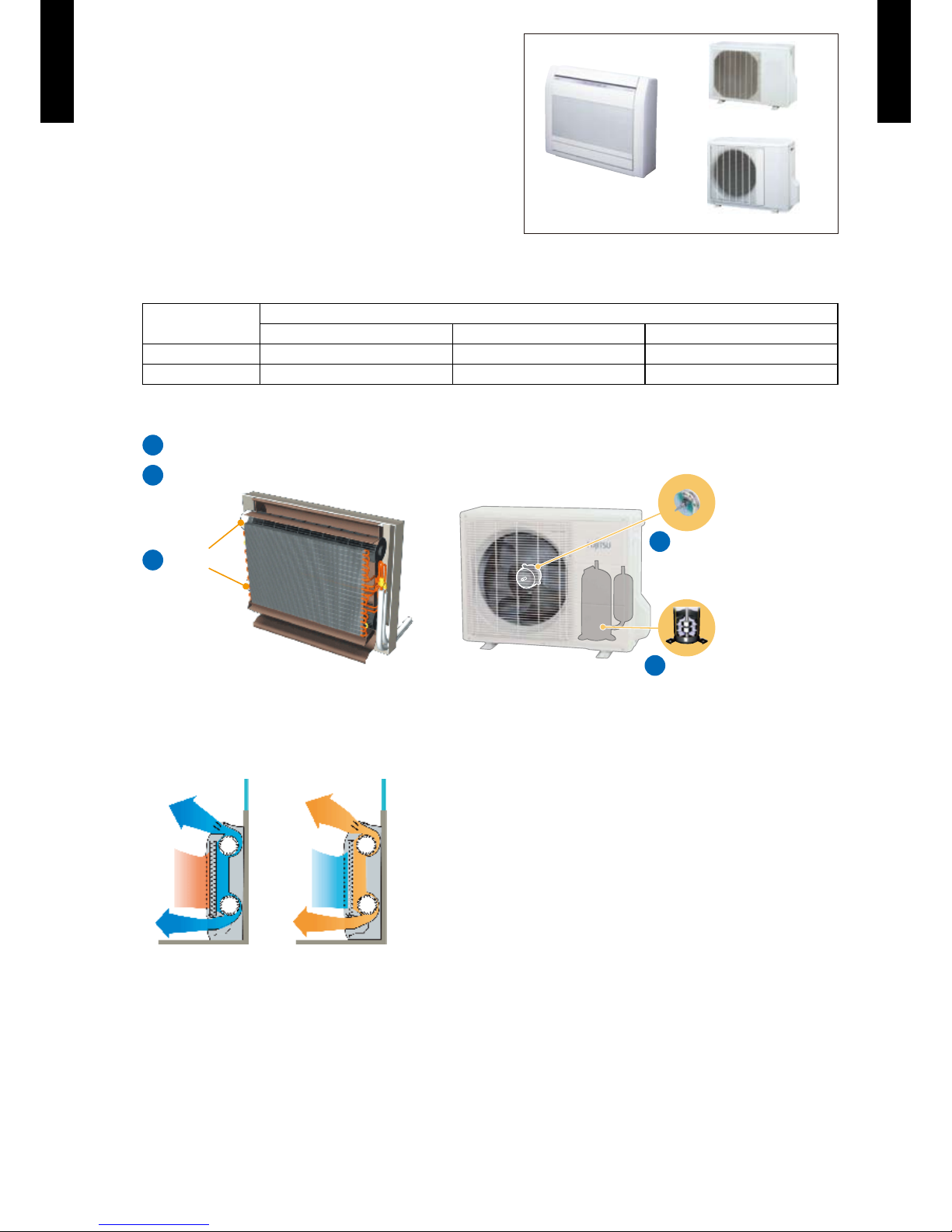
All DC
z
Up and down twin fan operation
z
Up to every corner of the room especially around the feet is heated evenly
by two-direction up and down discharge.
Cooling Heating
DC Fan motor
a
DC
compressor
b
a
DC
fan motor
DC compressor
b
DC fan motora
AOG09/12LVCA
AOG14LVL A
Page 5
- (01 - 02) -
FLOOR TYPE
AG
G0 9-14LV CA
FLOOR TYPE
AG
G0 9-14LV CA
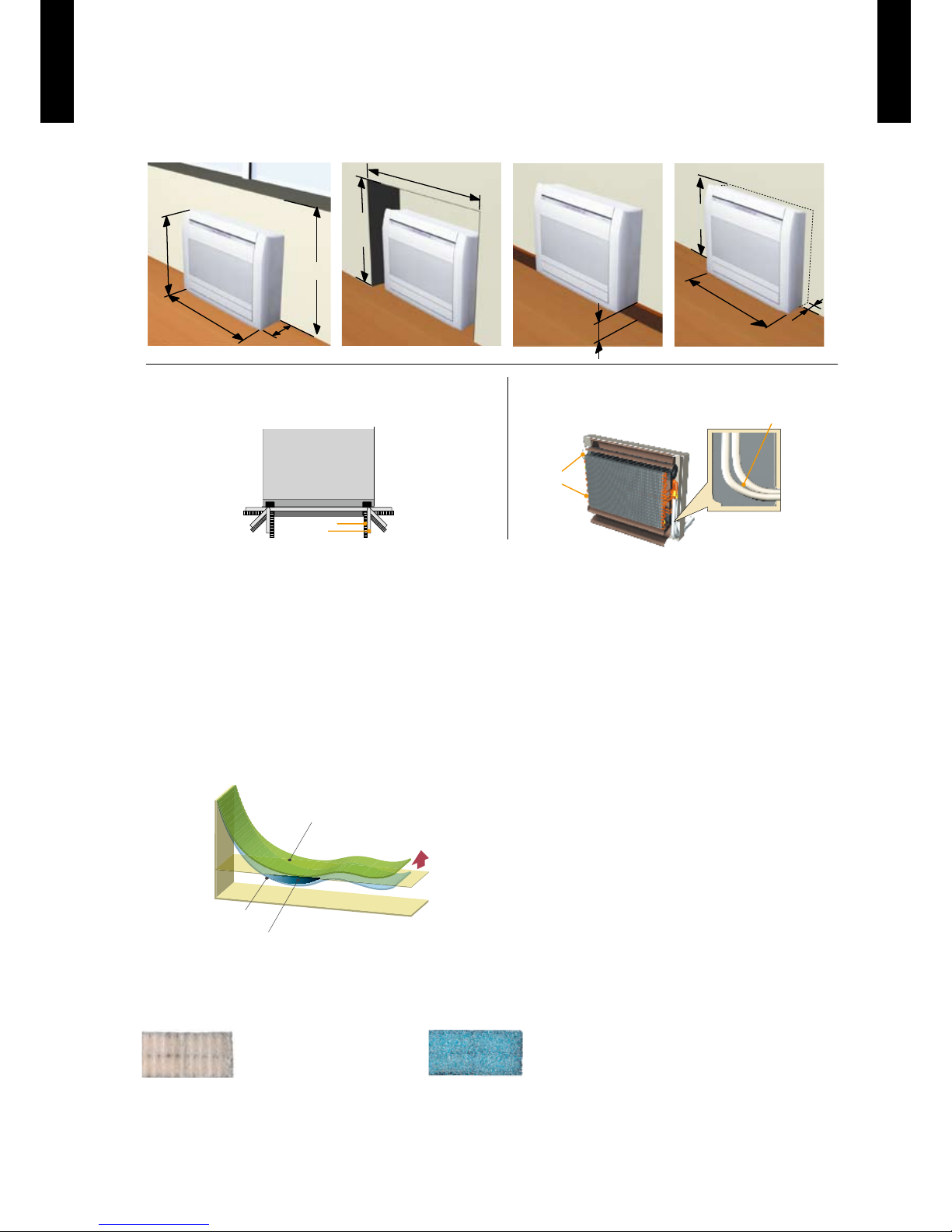
Flexible & easy installation
z
Piping space is wide and connection work is easy.
Beneath standard window Standard concave portion
Wall
Half concealed (Optional parts necessary)
(unit:mm)
600
740
200
700
(unit:mm)
Min.
700
Min.
590
Min.940
)mm:tinu()mm:tinu(
Max. 150
Min. 730
Max.
80
Space is wide and
piping work is easy
Fan motor
Front view
Large piping
bend R
Choice of 6-direction drain &
piping connection
Back view
Drain hose
Piping
1
6
52
3
4
Super quiet operation
z
Airow mode can be set in 4 steps and more detailed airow setting is possible.
10 °C heating operation
z
Operates in the 10 °C heating mode so that the room does not become too cold even
when you are absent during the winter, etc.
Economy operation
z
Example : Cooling operation
Temp.
Economy operation
Shift
setting
temp
Control maximum current
Normal operation
Time
Set temperature
Air conditioner lter feature
z
Apple-catechin lter Ion deodorization lter
Economy operation is energy saving, as the set •
temperature of indoor unit is shifted by 1 °C and
the maximum electric value of the outdoor unit is
suppressed.
Page 6
- (01 - 03) -
FLOOR TYPE
AG
G0 9-14LV CA
FLOOR TYPE
AG
G0 9-14LV CA
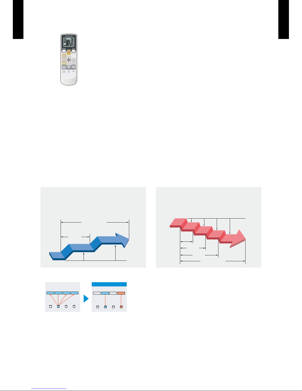
WIRELESS REMOTE CONTROLLER2.
FEATUR ES
4 mode timer setup available (ON / OFF / PROGRAM / SLEEP).
Easy operation.
Easy to change signal code (max. 4 units) by button operation.
Simple function setting
z
Setting of the air conditioner selection function is performed by remote controller.
Built-in timers
z
Select from four different timer programs (ON / OFF / PROGRAM / SLEEP).
Program timer
z
The program timer operates the on and off timer once within a 24 hour period.
Sleep timer
z
The sleep timer function automatically corrects the temperature thermostat setting according to
the timer setting to prevent excessive cooling and heating while sleeping.
60min.
1 °C
2 °C
Timer setting
Set
temp.
1 °C
30min.
60min.
90min.
2 °C
3 °C
4 °C
Set
temp.
Timer setting
Cooling operation/dry operation
When the sleep timer is set, the set temperature
automatically rises 1 °C every hour. The set
temperature can rise up to a maximum of 2 °C.
Heating operation
When the sleep timer is set, the set temperature
automatically drops 1 °C every 30 minutes. The set
temperature can drop to a maximum of 4 °C.
Switching remote controller signal code
z
A B C D
A B
C
D
Mixed-up
I.U. I.U. I.U. I.U.
I.U. I.U. I.U. I.U.
After code change
Code selector switch eliminates unit
•
being wrongly switched.
(Up to 4 codes can be set.)
*I.U.=Indoor unit
Page 7
- (01 - 04) -
FLOOR TYPE
AG
G0 9-14LV CA
FLOOR TYPE
AG
G0 9-14LV CA
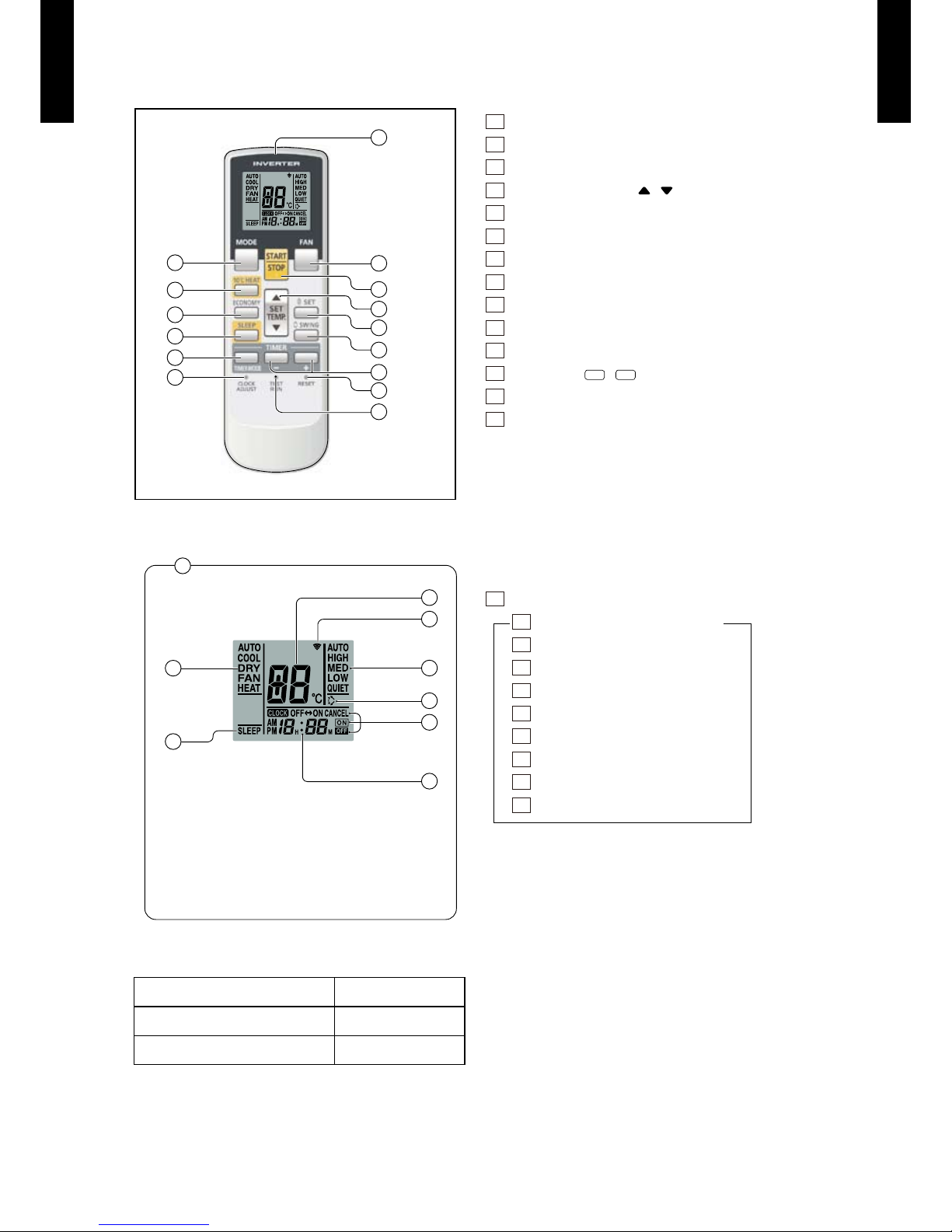
FUNCTIONS
Display panel
16
23
24
19
17
22
18
20
21
To facilitate explanation, the accompanying
illustration has been drawn to show all possible
indicators; in actual operation, however,
the display will only show those indicators
appropriate to the current operation.
SPECIFICATION
2
7
13
5
6
4
10
11
15
12
14
1
8
9
3
SIZE (H × W × D mm) 170 × 56 × 19
WEIGHT ( g ) 85 (w/o batteries)
ACCESSORY Holder
1
Signal transmitter
2
MODE button
3
10°C HEAT button
4
SET TEMP. button ( / )
5
ECONOMY button
6
SLEEP button
7
TIMER MODE button
8
FAN button
9
START/STOP button
10
SET button
11
SWING button
12
TIMER set (+ / -) button
13
CLOCK ADJUST button
14
TEST RUN button
•This button is used when installing the air conditioner, and should
not be used under normal conditions, as it will cause the indoor
unit’s thermostat function to operate incorrectly.
•If this button is pressed dur ing normal operation, the indoor
unit will switch to test operation mode, and the Indoor Unit’s
OPERATION Indicator Lamp and TIMER Indicator Lamp will
begin to ash simultaneously.
•To stop the test operation mode, press the SR ART/STOP button
to stop the air conditioner.
15
RESET button
16
Remote controller display
17
Transmit indicator
18
Fan speed indicator
19
Swing indicator
20
Timer mode indicator
21
Clock indicator
22
Temperature set indicator
23
Operation mode indicator
24
Sleep indicator
Functions will be dif ferent due to type of indoor unit.
For details, refer to the operation manual.
Page 8
- (01 - 05) -
FLOOR TYPE
AG
G0 9-14LV CA
FLOOR TYPE
AG
G0 9-14LV CA
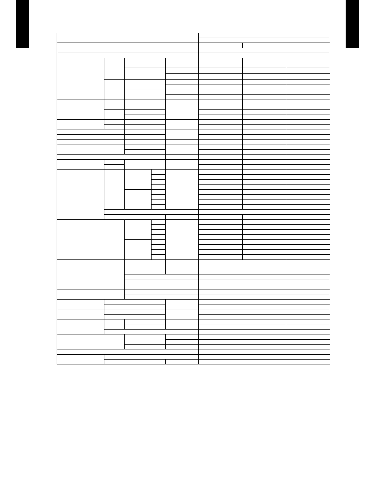
SPECIFICATIONS3.
NOTES:
l
Speci cations are base d on the foll owing conditio ns:
Cooli ng : Indoo r tempera ture of 27 °C DB/19 °CWB a nd outdoo r tempera ture of 35 °C DB/24 °CWB
Heati ng : Indoo r tempera ture of 20 °C DB/15° CWB an d outdoor t emperat ure of 7 °CD B/6 °CWB
Pipe len gth : 5 m, Hei ght dif ference : 0 m (O utdoor u nit–I ndoor un it)
l
The prote ctive fu nction m ight work w hen usin g it in enviro nment out o f the tempe rature ra nge ment ioned ab ove.
* : The maxi mum curr ent is the ma ximum value when op erated wi thin the o perati on range.
Typ e
FLOOR TYPE
INVERTER HEAT PUMP
Model name AGG09LVCA AGG12 LVCA AGG14 LVCA
Power sourc e 230 V~ 50 Hz
Available voltage range 198 –26 4V
Capacity
Cooling
Rated
kW 2.60 3.50 4.20
Btu/h 8,900 11, 90 0 14,30 0
Min.–Ma x.
kW 0.9–3.5 0.9– 4.0 0.9–5.0
Btu/h 3,100–11,900 3,100–13,600 3 ,100 –1 7,100
Heating
Rated
kW 3.50 4.50 5.20
Btu/h 11, 90 0 15,40 0 1 7,70 0
Min.–Ma x.
kW 0.9–5.5 0.9– 6.6 0.9– 8.0
Btu/h 3,100–18,800 3,100–22,500 3,100–27,300
Input power
Cooling
Rated
kW
0.53 0.94 1.14
Min.–Ma x. 0.2 5 –1.3 5 0.2 5 –1.4 0 0.2 5 –1.9 0
Heating
Rated 0.79 1 .19 1.4 4
Min.–Ma x. 0 .25 – 2.10 0. 25 –2 .15 0.25 –2.95
Current
Cooling Rated
A
2.6 4.4 5.2
Heating Rated 3.8 5.5 6.4
EER Cooling
kW/kW
4.91 3 .72 3.68
COP Heating 4.43 3.78 3. 61
Sensible capacity Cooling kW 2.33 2.66 3 .15
Power factor
Cooling
%
90 93 96
Heating 90 94 98
Moisture removal l/h (pint s/h) 1.3 (2.3) 1.8 (3.2) 2.1 (3.7)
Maximum operating
current *
Cooling
Max. A
7.0 7. 0 9.0
Heating 10.0 10.0 13 .5
Fan
Airow
rate
Cooling
(UPPER :
LOWER)
High
m3/h
570 570 650
Med 460 460 520
Low 360 360 400
Quiet 270 270 270
Heating
(UPPER :
LOWER)
High 600 600 650
Med 480 480 520
Low
370 370 390
Quiet 270 270 270
Type × Q'ty Cross ow fan × 2
Motor output W 16 × 2 16 × 2 16 × 2
Sound pressure level
Cooling
High
dB (A)
40 40 44
Med 35 35 38
Low 29 29 31
Quiet 2 2 22 22
Heating
High 40 40 43
Med 35 35 37
Low 29 29 29
Quiet 2 2 22 22
Heat exchanger type
Dimensions
(H × W × D)
mm
378 × 550 × 26.6
Fin pitch 1.2
Rows × stages 2 × 18
Pipe type Copper
Fin type Aluminium
Enclosure
Material Polystyrene
Colour White
Dimensions
(H × W × D)
Net
mm
600 × 740 × 200
Gross 700 × 820 × 310
Weight
Net
kg
14
Gross 17
Connection pipe
Size
Liquid
mm
Ø 6.35 (Ø 1/4 in.)
Gas Ø 9.52 (Ø 3/8 in.) Ø 12.70 (Ø 1/2 in.)
Method Flare
Operation range
Cooling
°C 18 to 32
%RH 80 or less
Heating °C 30 or less
Remote controller type Wireless
Drain hose
Material PP + LLDPE
Size mm Ø 13.8 (I.D.), Ø 15.8 to Ø 16.7 (O.D.)
Page 9
- (01 - 06) -
FLOOR TYPE
AG
G0 9-14LV CA
FLOOR TYPE
AG
G0 9-14LV CA
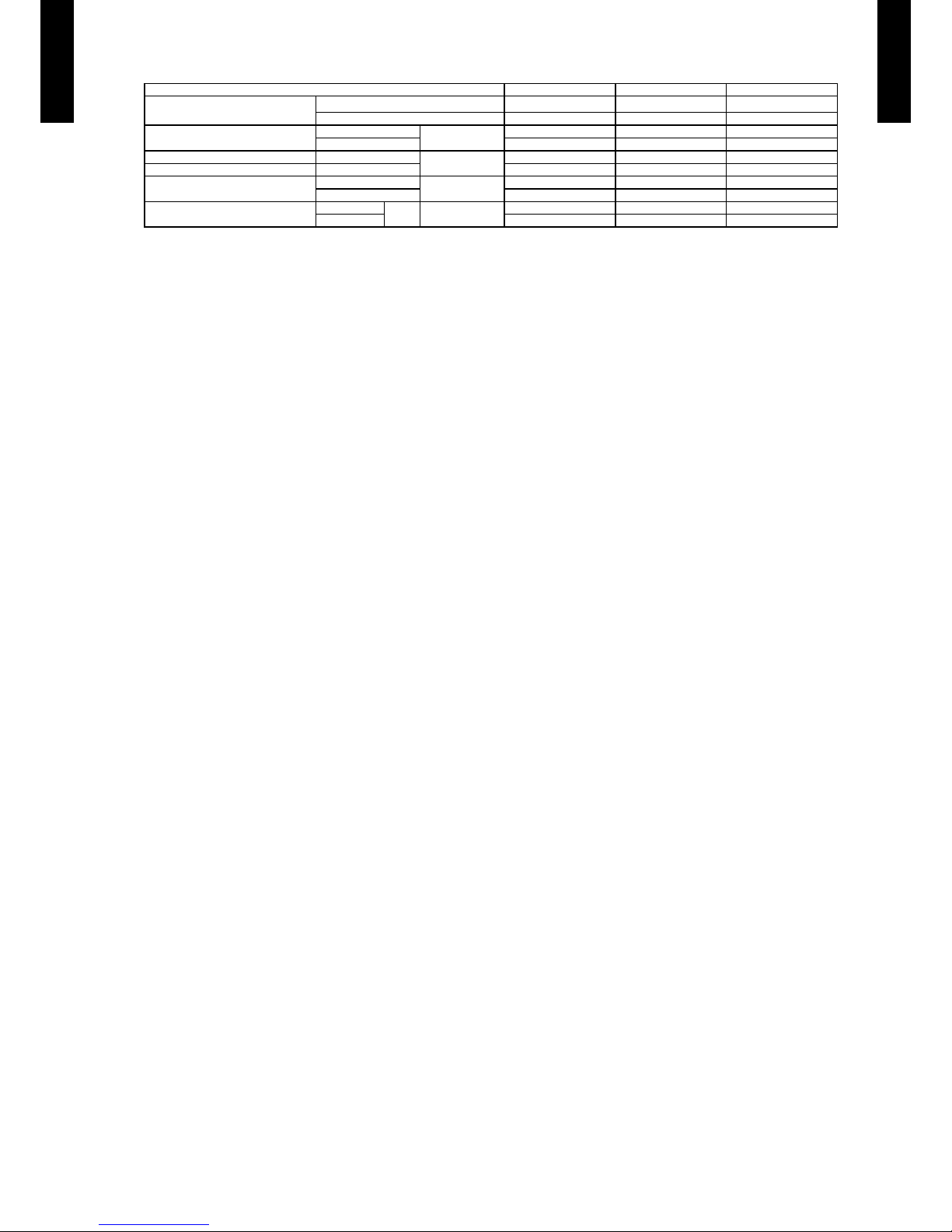
Model name AGG09LVCA AGG12 LVCA AGG14 LVCA
Energy ef ciency class
Cooling A++ A++ A++
Heating (Average) A+ A+ A+
Pdesign
Cooling
kW
2.6 (35 °C) 3.5 (35 °C) 4.2 (35 °C)
Heating (Average) 2.9 (-10 °C) 3.8 (-10 °C) 4.7 (-10 °C)
SEER Cooling
kWh/kWh
7.00 6.50 6.40
SCOP Heating (Average) 4.20 4.00 4.00
Annual energy consumption
QCE
kWh/a
130 18 8 230
QHE (Average) 967 1330 1645
Sound power level
Cooling
High dB (A)
55 55 58
Heating 56 56 58
Page 10
- (01 - 07) -
FLOOR TYPE
AG
G0 9-14LV CA
FLOOR TYPE
AG
G0 9-14LV CA
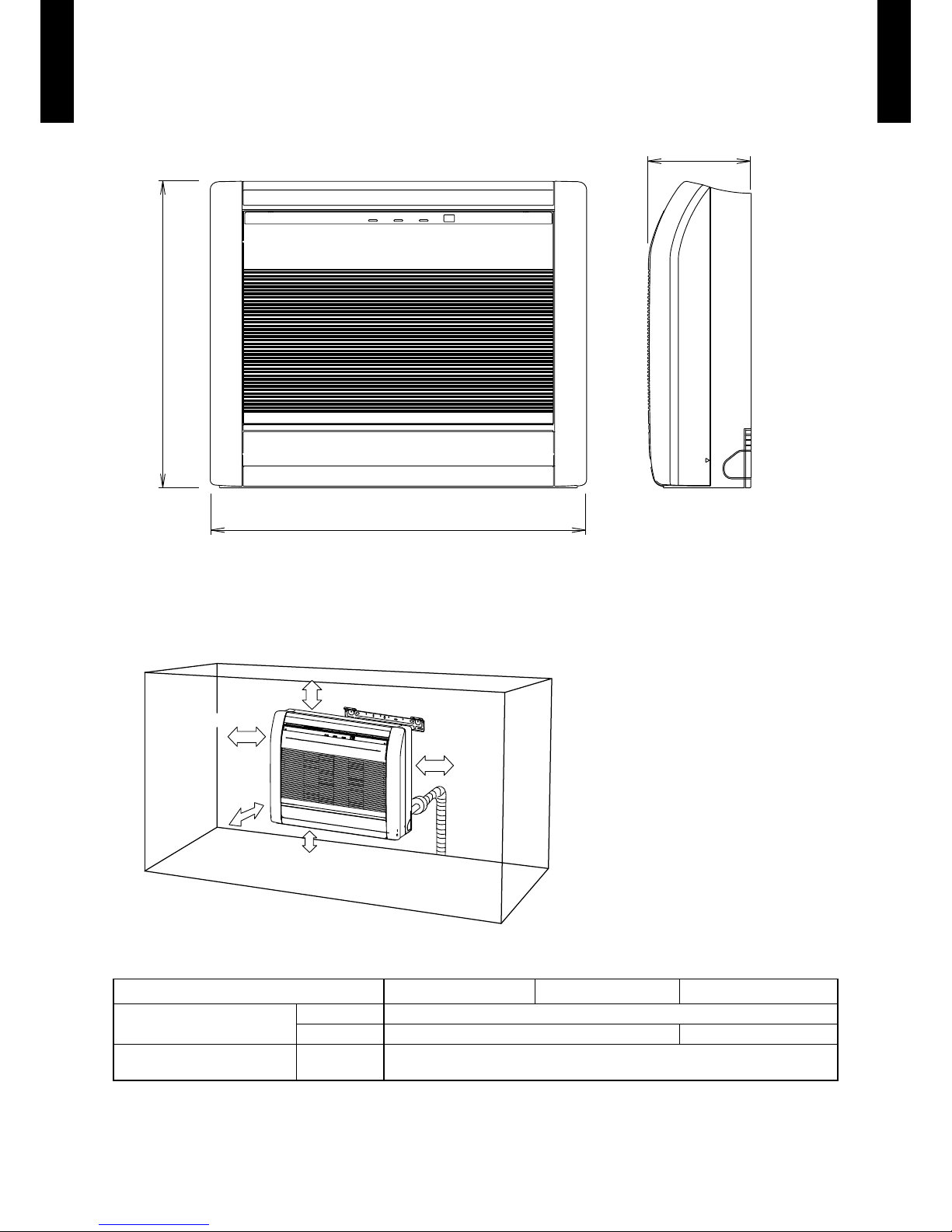
DIMENSIONS4.
MODEL : AGG09LVCA, AGG12LVCA, AGG14LVCA
(Unit : mm)
200
600
740
Front view
Side view
INSTALLATION PLACE
10 cm or more
8 cm or more
8 cm or more
5 cm or
more
15 cm or below
from the floor
AGG09LVCA AGG12LVCA AGG14LVCA
Refrigerant pipe are
connection
Liquid Ø 6.35 mm (Ø 1/4 in.)
Gas Ø 9.52 mm (Ø 3/8 in.) Ø 12.7 mm (Ø 1/2 in.)
Drain hose connection Drain hose
Ø 13.8 (I.D.), Ø 15.8 to Ø 16.7 (O.D.)
Drain hose : L=600 mm
Page 11

- (01 - 08) -
FLOOR TYPE
AG
G0 9-14LV CA
FLOOR TYPE
AG
G0 9-14LV CA
WIRING DIAGRAMS5.
MODEL : AGG09LVCA, AGG12LVCA, AGG14LVCA
TO OUTDOOR UNIT
Page 12
- (01 - 09) -
FLOOR TYPE
AG
G0 9-14LV CA
FLOOR TYPE
AG
G0 9-14LV CA
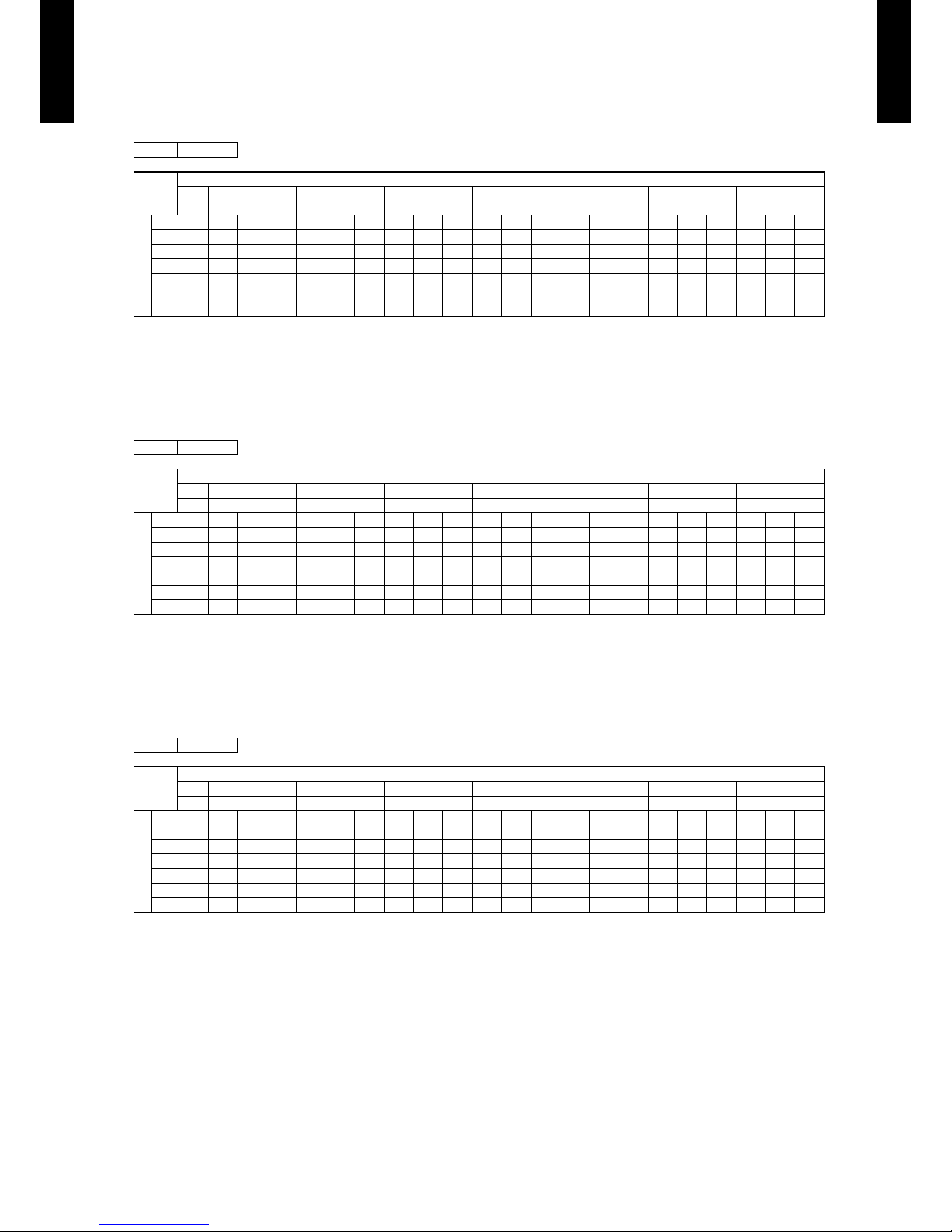
CAPACITY TABLE6.
COOLING CAPACITY6-1.
MODEL : AGG09LVCA
MODEL : AGG12LVCA
MODEL : AGG14LVCA
AFR: Air ow Rate (m³/min.)
TC: Total Capaci ty (kW)
SHC: Sens ible Hea t Capacit y (kW)
IP: Input Po wer (kW)
AFR 9.5
Indoor temperature
°CDB 18 21 23 25 27 29 32
°CWB 12 15 16 18 19 21 23
Outdoor temperature
°CDB TC SHC IP TC SHC IP TC SHC IP TC SHC IP TC SHC IP TC SHC IP TC SHC IP
20 1.99 1.88 0.25 2.21 1.89 0.25 2.29 2.05 0.26 2.44 2.06 0.26 2.51 2.23 0.26 2.67 2.22 0.26 2.82 2.36 0.27
25 2.27 2.15 0.41 2.53 2.16 0.42 2.61 2.35 0.42 2.79 2.35 0.43 2.87 2.54 0.43 3.04 2.53 0.43 3.22 2.70 0.44
30 2.16 2.05 0.46 2.41 2.06 0.47 2.49 2.24 0.47 2.66 2.24 0.48 2.74 2.42 0.48 2.90 2.41 0.48 3.07 2.57 0.49
35 2.05 1.94 0.51 2.29 1.95 0.52 2.37 2.12 0.52 2.52 2.13 0.53 2.60 2.30 0.53 2.76 2.29 0.54 2.91 2.44 0.54
40 1.90 1.80 0.53 2.12 1.81 0.54 2.19 1.97 0.55 2.34 1.98 0.55 2.41 2.13 0.55 2.56 2.13 0.56 2.70 2.26 0.57
43 1.87 1.77 0.54 2.08 1.78 0.55 2.15 1.93 0.55 2.30 1.94 0.56 2.37 2.10 0.56 2.51 2.09 0.57 2.65 2.22 0.57
AFR 9.5
Indoor temperature
°CDB 18 21 23 25 27 29 32
°CWB 12 15 16 18 19 21 23
Outdoor temperature
°CDB TC SHC IP TC SHC IP TC SHC IP TC SHC IP TC SHC IP TC SHC IP TC SHC IP
20 2.67 2.17 0.45 2.98 2.19 0.45 3.08 2.38 0.45 3.28 2.39 0.46 3.38 2.58 0.46 3.59 2.57 0.47 3.79 2.73 0.47
25 3.05 2.48 0.74 3.40 2.50 0.75 3.52 2.72 0.75 3.75 2.73 0.76 3.87 2.94 0.76 4.10 2.93 0.77 4.33 3.12 0.78
30 2.91 2.37 0.82 3.24 2.38 0.83 3.36 2.59 0.84 3.58 2.60 0.85 3.69 2.81 0.85 3.91 2.79 0.86 4.13 2.98 0.87
35 2.76 2.25 0.91 3.08 2.26 0.92 3.18 2.46 0.93 3.39 2.47 0.94 3.50 2.66 0.94 3.71 2.65 0.95 3.92 2.83 0.96
40 2.56 2.08 0.95 2.86 2.10 0.96 2.95 2.28 0.97 3.15 2.29 0.98 3.25 2.47 0.98 3.44 2.46 0.99 3.63 2.62 1.00
43 2.52 2.05 0.96 2.80 2.06 0.97 2.90 2.24 0.98 3.09 2.25 0.99 3.19 2.43 0.99 3.38 2.42 1.00 3.57 2.57 1.01
AFR 10.8
Indoor temperature
°CDB 18 21 23 25 27 29 32
°CWB 12 15 16 18 19 21 23
Outdoor temperature
°CDB TC SHC IP TC SHC IP TC SHC IP TC SHC IP TC SHC IP TC SHC IP TC SHC IP
20 3.42 2.61 0.62 3.81 2.63 0.63 3.94 2.86 0.63 4.20 2.87 0.64 4.33 3.10 0.64 4.59 3.08 0.65 4.85 3.28 0.66
25 3.66 2.80 0.91 4.08 2.81 0.92 4.22 3.06 0.93 4.50 3.07 0.93 4.64 3.31 0.94 4.91 3.30 0.95 5.19 3.51 0.96
30 3.50 2.67 1.00 3.90 2.69 1.02 4.03 2.92 1.02 4.30 2.93 1.03 4.43 3.16 1.04 4.69 3.15 1.05 4.96 3.36 1.06
35 3.32 2.53 1.10 3.70 2.55 1.12 3.82 2.77 1.12 4.07 2.78 1.13 4.20 3.00 1.14 4.45 2.99 1.15 4.70 3.18 1.16
40 2.94 2.25 1.14 3.28 2.26 1.16 3.39 2.46 1.17 3.61 2.47 1.18 3.73 2.66 1.19 3.95 2.65 1.20 4.17 2.82 1.21
43 2.78 2.12 1.16 3.10 2.13 1.17 3.20 2.32 1.18 3.41 2.33 1.19 3.52 2.51 1.20 3.73 2.50 1.21 3.94 2.67 1.22
Page 13
- (01 - 10) -
FLOOR TYPE
AG
G0 9-14LV CA
FLOOR TYPE
AG
G0 9-14LV CA
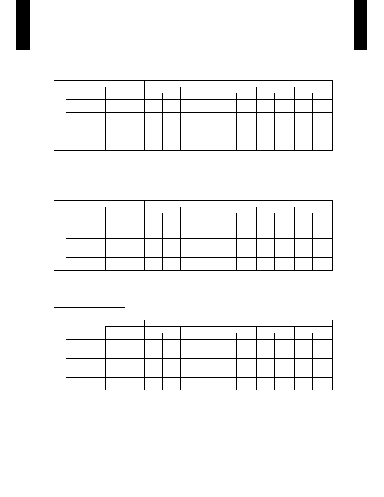
HEATING CAPACITY6-2.
This table is created using the maximum capacity.
MODEL :
AGG09LVCA
MODEL :
AGG12LVCA
MODEL :
AGG14LVCA
AFR: Air ow Rate (m³/min.)
TC: Total Capaci ty (kW)
IP: Input Po wer (kW)
AFR 10.0
Indoor temperature
°CDB 16 18 20 22 24
Outdoor temperature
°CDB °CWB TC IP TC IP TC IP TC IP TC IP
-15 -16 2.61 0.99 2.54 1.01 2.48 1.03 2.42 1.05 2.36 1.07
-10 -11 3.27 1.13 3.19 1.16 3.11 1.18 3.04 1.20 2.96 1.23
-5 -7 3.91 1.29 3.82 1.32 3.72 1.34 3.63 1.37 3.54 1.40
0 -2 4.51 1.47 4.41 1.50 4.30 1.53 4.19 1.56 4.08 1.59
5 3 5.38 1.85 5.25 1.88 5.13 1.92 5.00 1.96 4.87 2.00
7 6 5.20 1.74 5.08 1.78 4.95 1.81 4.83 1.85 4.71 1.89
10 8 5.97 1.76 5.83 1.80 5.69 1.83 5.55 1.87 5.41 1.91
15 10 5.98 1.66 5.83 1.70 5.69 1.73 5.55 1.77 5.41 1.80
AFR 10.0
Indoor temperature
°CDB 16 18 20 22 24
Outdoor temperature
°CDB °CWB TC IP TC IP TC IP TC IP TC IP
-15 -16 3.34 1.40 3.26 1.43 3.18 1.46 3.10 1.49 3.02 1.52
-10 -11 3.91 1.52 3.82 1.55 3.73 1.58 3.63 1.62 3.54 1.65
-5 -7 4.47 1.65 4.36 1.69 4.26 1.72 4.15 1.75 4.04 1.79
0 -2 4.99 1.80 4.87 1.84 4.76 1.87 4.64 1.91 4.52 1.95
5 3 5.76 2.01 5.62 2.05 5.48 2.10 5.35 2.14 5.21 2.18
7 6 5.57 1.90 5.43 1.94 5.30 1.98 5.17 2.02 5.04 2.06
10 8 6.39 1.92 6.24 1.96 6.09 2.00 5.94 2.04 5.78 2.08
15 10 6.39 1.81 6.24 1.85 6.09 1.89 5.94 1.93 5.79 1.96
AFR 10.8
Indoor temperature
°CDB 16 18 20 22 24
Outdoor temperature
°CDB °CWB TC IP TC IP TC IP TC IP TC IP
-15 -16 4.21 1.98 4.11 2.02 4.01 2.06 3.91 2.10 3.81 2.14
-10 -11 5.01 2.20 4.89 2.25 4.77 2.30 4.65 2.34 4.53 2.39
-5 -7 5.72 2.46 5.59 2.51 5.45 2.56 5.31 2.61 5.18 2.67
0 -2 6.44 2.72 6.28 2.78 6.13 2.83 5.98 2.89 5.82 2.95
5 3 6.59 2.44 6.43 2.49 6.27 2.54 6.12 2.59 5.96 2.64
7 6 6.62 2.20 6.46 2.25 6.30 2.29 6.14 2.34 5.99 2.39
10 8 6.23 2.22 6.08 2.27 5.93 2.31 5.78 2.36 5.63 2.40
15 10 6.57 1.85 6.41 1.89 6.25 1.93 6.10 1.97 5.94 2.01
Page 14
- (01 - 11) -
FLOOR TYPE
AG
G0 9-14LV CA
FLOOR TYPE
AG
G0 9-14LV CA
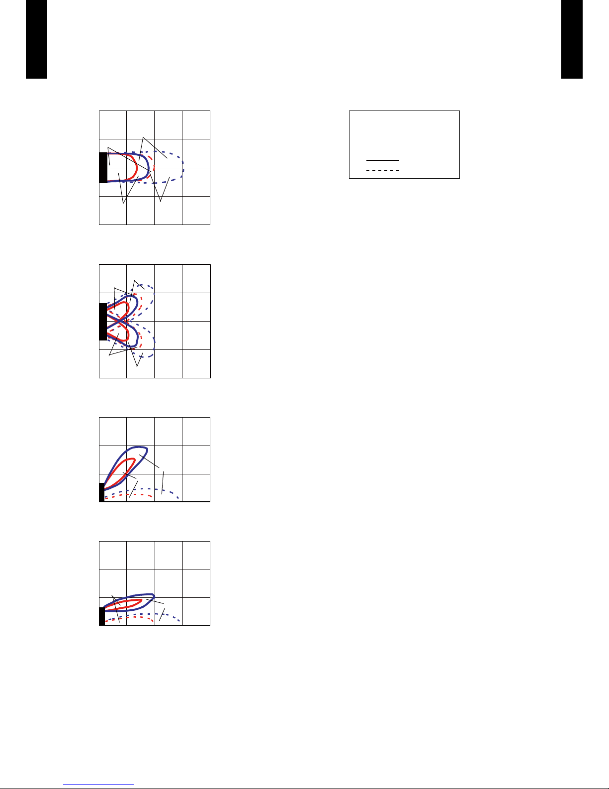
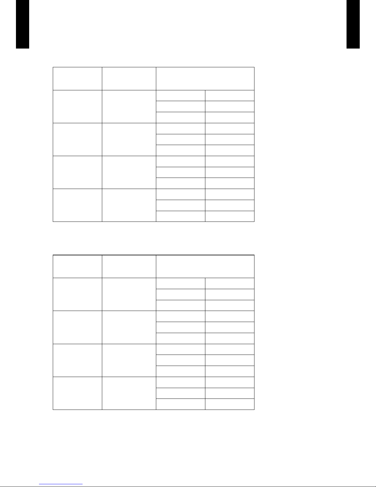
FAN PERFORMANCE AND CAPACITY7.
AIR VELOCITY DISTRIBUTION7-1.
MODEL : AGG09LVCA, AGG12LVCA, AGG14LVCA
Conditions:
Fan speed : HI
Operation mode : FAN
Fan select : U PPER&LOWER
: UPPER FAN
: LOWER FAN
0.5
UPPER
LOWER
1.0
2
1
0
1
2
Unit : m/s(m)
(m)
TOP VIEW
FLOW CONTR OL PANEL : H oriz.
LOUVER : Ce nter
0 1 2 3 4
0.5
1.0
0.5
1.0
2
1
0
1
2
Unit : m/s(m)
(m)
TOP VIEW
FLOW CONTR OL PANEL : H oriz.
LOUVER : Ri ght & Left
0 1 2 3 4
1.0
0.5
3
2
1
0
Unit : m/s(m)
SIDE VIE W
FLOW CONTR OL PANEL : Ver t
LOUVER : Ce nter
(m)
0 1 2 3 4
1.0
0.5
3
2
1
0
Unit : m/s(m)
SIDE VIE W
FLOW CONTR OL PANEL : H oriz.
LOUVER :C enter
(m)
0 1 2 3 4
Page 15
- (01 - 12) -
FLOOR TYPE
AG
G0 9-14LV CA
FLOOR TYPE
AG
G0 9-14LV CA
AIRFLOW7-2.
MODEL : AGG09LVCA, AGG12LVCA
Cooling
z
z
Heating
Fan speed
Number of rotations
[r.p.m]
(UPPER/LOWER)
Airow
HIGH
1190/1000
m³/h
570
l/s
158
CFM
335
MED
1000/850
m³/h
460
l/s
128
CFM
271
LOW
820/690
m³/h
360
l/s
100
CFM
212
QUIET
660/560
m³/h
270
l/s
75
CFM
159
Fan speed
Number of rotations
[r.p.m]
(UPPER/LOWER)
Airow
HIGH
1240/1040
m³/h
600
l/s
167
CFM
353
MED
1040/880
m³/h
480
l/s
133
CFM
282
LOW
840/700
m³/h
370
l/s
103
CFM
218
QUIET
660/560
m³/h
270
l/s
75
CFM
159
Page 16

- (01 - 13) -
FLOOR TYPE
AG
G0 9-14LV CA
FLOOR TYPE
AG
G0 9-14LV CA
MODEL : AGG14LVCA
Cooling
z
z
Heating
Fan speed
Number of rotations
[r.p.m]
(UPPER/LOWER)
Airow
HIGH
13 30 /112 0
m³/h
650
l/s
181
CFM
383
MED
110 0/ 93 0
m³/h
520
l/s
144
CFM
306
LOW
890/750
m³/h
400
l/s
111
CFM
235
QUIET
660/560
m³/h
270
l/s
75
CFM
159
Fan speed
Number of rotations
[r.p.m]
(UPPER/LOWER)
Airow
HIGH
13 30 /112 0
m³/h
650
l/s
181
CFM
383
MED
110 0/ 93 0
m³/h
520
l/s
144
CFM
306
LOW
860/730
m³/h
390
l/s
108
CFM
230
QUIET
660/560
m³/h
270
l/s
75
CFM
159
Page 17

- (01 - 14) -
FLOOR TYPE
AG
G0 9-14LV CA
FLOOR TYPE
AG
G0 9-14LV CA
OPERATION NOISE (SOUND PRESSURE)8.
NOISE LEVEL CURVE8-1.
MODEL : AGG09LVCA
Cooling
z
Octave ba nd sound p ressur e level, dB : (0 d B=0. 0002 µ bar)
Octave ba nd cente r freque ncy, Hz
80
70
60
50
40
30
20
10
0
63 125 250 5 00 1,000 2,00 0 4,000 8 ,000
NC-65
NC-60
NC-55
NC-50
NC-45
NC-40
NC-35
NC-30
NC-25
NC-20
NC -15
High
Quiet
Heating
z
Octave ba nd sound p ressur e level, dB : (0 d B=0. 0002 µ bar)
Octave ba nd cente r freque ncy, Hz
80
70
60
50
40
30
20
10
0
63 125 250 5 00 1,000 2,00 0 4,000 8 ,000
NC-65
NC-60
NC-55
NC-50
NC-45
NC-40
NC-35
NC-30
NC-25
NC-20
NC -15
High
Quiet
NC-65
NC-60
NC-55
NC-50
NC-45
NC-40
NC-35
NC-30
NC-25
NC-20
NC -15
Octave ba nd sound p ressur e level, dB : (0 d B=0. 0002 µ bar)
Octave ba nd cente r freque ncy, Hz
80
70
60
50
40
30
20
10
0
63 125 250 5 00 1,000 2,00 0 4,000 8 ,000
MODEL : AGG12LVCA
Cooling
z
High
Quiet
Heating
z
Octave ba nd sound p ressur e level, dB : (0 d B=0. 0002 µ bar)
Octave ba nd cente r freque ncy, Hz
80
70
60
50
40
30
20
10
0
63 125 250 5 00 1,000 2,00 0 4,000 8 ,000
NC-65
NC-60
NC-55
NC-50
NC-45
NC-40
NC-35
NC-30
NC-25
NC-20
NC -15
High
Quiet
Page 18

- (01 - 15) -
FLOOR TYPE
AG
G0 9-14LV CA
FLOOR TYPE
AG
G0 9-14LV CA
MODEL : AGG14LVCA
Cooling
z
Octave ba nd sound p ressur e level, dB : (0 d B=0. 0002 µ bar)
Octave ba nd cente r freque ncy, Hz
80
70
60
50
40
30
20
10
0
63 125 250 5 00 1,000 2,00 0 4,000 8 ,000
NC-65
NC-60
NC-55
NC-50
NC-45
NC-40
NC-35
NC-30
NC-25
NC-20
NC -15
High
Quiet
Heating
z
Octave ba nd sound p ressur e level, dB : (0 d B=0. 0002 µ bar)
Octave ba nd cente r freque ncy, Hz
80
70
60
50
40
30
20
10
0
63 125 250 5 00 1,000 2,00 0 4,000 8 ,000
NC-65
NC-60
NC-55
NC-50
NC-45
NC-40
NC-35
NC-30
NC-25
NC-20
NC -15
High
Quiet
Page 19

- (01 - 16) -
FLOOR TYPE
AG
G0 9-14LV CA
FLOOR TYPE
AG
G0 9-14LV CA
SOUND LEVEL CHECK POINT8-2.
Microphone Microphone
●●Airflow
1 m
Airflow
1 m
Page 20

- (01 - 17) -
FLOOR TYPE
AG
G0 9-14LV CA
FLOOR TYPE
AG
G0 9-14LV CA
ELECTRIC CHARACTERISTICS9.
Model Name AGG09 LVCA AGG12LVC A AGG14LVC A
Power Supply
Voltage V 230 ~
Frequency Hz 50
Max Operating Current A 0.7
Wiring Spec. *
Connection Cable mm
2
1.5
Limited wiring length m 21
*: Selected sample based on Japan Electrotechnical Standards and Codes Committee E0005.
Page 21

- (01 - 18) -
FLOOR TYPE
AG
G0 9-14LV CA
FLOOR TYPE
AG
G0 9-14LV CA
SAFETY DEVICES10.
Protection form
Model
AGG0 9LVCA
AGG12LVCA
AGG14LVCA
Circuit protection Current fuse (PC board)
250 V 3.15 A
Terminal protection Current (thermal) fuse
250 V 3 A
Fan motor protection Terminal protection program
OFF : 150 ± 15 °C
ON : 120 ± 15 °C
Page 22

- (01 - 19) -
FLOOR TYPE
AG
G0 9-14LV CA
FLOOR TYPE
AG
G0 9-14LV CA
EXTERNAL INPUT & OUTPUT11.
Connector
INPUT
OUTPUT REMARKS
CN14 Control input -
See external input/output
settings for details.
CN20 - Operation status output
EXTERNAL INPUT11-1.
CONTROL INPUT (Operation/Stop or Forced stop)
The air conditioner can be remotely operated by means of the following on-site work.
"Operation/Stop" mode or "Forced stop" mode can be selected with function setting of indoor unit.
Unit operation is started at the following contents by adding the contact input of a commercial ON/OFF switch to a
connector on the external control PC board and turning it ON.
Unit operation Initial setting after power is ON Starting mode other than initial setting
Operation mode Auto changeover Mode at previous operation
Set temperature 24 °C Temperature at previous operation
Airow mode AUTO Mode at previous operation
Up-down air direction (swing) Standard air direction (swing OFF) Air direction at previous operation
Left-right air direction (swing) Standard air direction (swing OFF) Air direction at previous operation
Circuit diagram example
z
Indoor unit
control PC board
Connector
1
3
Signal
Field supply
10 m*
Connected unit
Ex.) Switch
Contact capacity : DC 24 V or more, 10 mA or more.
*: Make the distance from the PC board to the connected unit within 10 m.
When function setting is "Operation/Stop" mode ●
Operation
Stop
ON
OFF
Input signal
Indoor unit
When function setting is in "Forced stop" mode ●
Remote controller
ON ON ON
Input signal
ON
OFF
Indoor unit
Operation
Stop
Command
Forced stop
Normal
Remote control
operation invalidity
Page 23

- (01 - 20) -
FLOOR TYPE
AG
G0 9-14LV CA
FLOOR TYPE
AG
G0 9-14LV CA
Parts (Optional)
z
Parts name Model name
External connect kit U T Y-XW ZX
Page 24

- (01 - 21) -
FLOOR TYPE
AG
G0 9-14LV CA
FLOOR TYPE
AG
G0 9-14LV CA
EXTERNAL OUTPUT11-2.
OPERATION STATUS OUTPUT
An air conditioner operation status signal can be output.
Circuit diagram example
z
Relay spec.:
Max .DC 24 V, 10 mA to less
than 500 mA.
Field supply
Ex.) Display
Indoor unit
control PC board
Connected unit
Ex.) Relay unit
1
2
Signal
Relay
power
supply
V
Connector
10 m*
DC 24 V
* Make the distance from the PC board to the connected unit within 10 m.
ON
OFF
Operation
Stop
Indoor unit
Output signal
Parts (Optional)
z
Parts name Model name
External connect kit U T Y-XW ZX
Page 25

- (01 - 22) -
FLOOR TYPE
AG
G0 9-14LV CA
FLOOR TYPE
AG
G0 9-14LV CA
FUNCTION SETTINGS12.
INDOOR UNIT (Setting by remote controller)12-1.
• The function settings of the control of the indoor unit can be changed by this procedure according
to the installation conditions. Incorrect settings may cause an indoor unit malfunction.
After turning on the power, perform the Function Setting according to the installation conditions •
by using the remote controller.
The settings may be selected between the following two: Function Number or Setting Value. •
Settings will not be changed if invalid numbers or setting values are selected. •
PREPARATION
Before turning on the power of the indoor units: •
- Conrm that whether the piping air-tight test and vacuuming have been conducted.
- Reconrm that whether there is no miswiring.
Turn on the power of the indoor units. •
FUNCTION SETTING METHOD (for Wireless remote controller)
Entering the Function Setting Mode
While pressing the FAN button and SET TEMP. (
•
) simultaneously, press the RESET button to enter the function
setting mode.
STEP 1
Setting the Remote controller Signal Code
Use the following steps to select the signal code of the remote controller. (Note that
the air conditioner cannot receive a signal code if the air conditioner has not been set
for the signal code.) The signal codes that are set through this process are applicable
only to the signals in the Function Setting. For details on how to set the signal codes
through the normal process, refer to REMOTE CONTROLLER SIGNAL CODE
SETTING.
Press the SET TEMP. (1. ) ( ) button to change the signal code between →
→ → Match the code on the display to the air conditioner signal code. (initially
set to )
(If the signal code does not need to be selected, press the MODE button and
proceed to STEP 2.)
Press the TIMER MODE button and check that the indoor unit can receive signals 2.
at the displayed signal code.
Press the MODE button to accept the signal code, and proceed to STEP 2.3.
The air conditioner signal code is set to A prior to shipment.
The remote controller resets to signal code A when the batteries in the remote controller are replaced. If you use a
signal code other than signal code A, reset the signal code after replacing the batteries.
If you do not know the air conditioner signal code setting, try each of the signal codes ( → → → ) until you
nd the code which operates the air conditioner.
STEP 2
Selecting the Function Number and Setting Value
Press the SET TEMP. (1. ) ( ) buttons to select the function
numbe r.
(Press the MODE button to switch between the left and right
digits.)
Press the FAN button to proceed to setting the value. 2.
Press the FAN button again to return to the function number
selection.)
Press the SET TEMP. (3. ) ( ) buttons to select the setting
value.
(Press the MODE button to switch between the left and right
digits.)
Press the TIMER MODE button, and START/STOP button, 4.
in the order listed to conrm the settings.
Press the RESET button to cancel the function setting 5.
mode.
After completing the Function Setting, be sure to turn off the 6.
power and turn it on again.
Function number
Setting value
CAUTION
After turning off the power, wait 30 seconds or more before turning on it again.
The Function Setting will not become active unless the power is turned off on again.
Page 26

- (01 - 23) -
FLOOR TYPE
AG
G0 9-14LV CA
FLOOR TYPE
AG
G0 9-14LV CA
CONTENTS OF FUNCTION SETTING
Follow the instructions in the Local Setup Procedure, which is supplied with the remote controller, in •
accordance with the installed condition.
After turning on the power, perform the Function Setting by using the remote controller.
The settings may be selected between the following two: Function Number or Setting Value. •
Settings will not be changed if invalid numbers or setting values are selected. •
1) Filter sign
2) Vertical airow direction range control
3) Room temperature control for cooling
4) Room temperature control for heating
5) Auto restart
6) Room temperature sensor switching
7) Remote controller signal code
8) External input control
9) Indoor unit fan control for energy saving for cooling
1) Filter sign
Select appropriate intervals for displaying the lter sign on the indoor unit according to the
estimated amount of dust in the air of the room.
If the indication is not required, select "No indication" (03).
(. . .Factory setting)
Setting Description Function Number Setting Value
Standard (400 hours)
11
00
Long interval (1,000 hours) 01
Short interval (200 hours) 02
No indication 03
2) Vertical airow direction range control
In a concealed installation, change the setting to "Fixed" (02) to restrict the movement of the upper
air outlet so that the airow is only towards the horizontal direction.
(. . .Factory setting)
Setting Description Function Number Setting Value
Standard
23
00
(Setting prohibited) 01
Fixed (Concealed) 02
3) Room temperature control for cooling
Depending on the installed environment, correction of the room temperature sensor may be
required.
Select the appropriate control setting according to the installed environment.
(. . .Factory setting)
Setting Description Function Number Setting Value
Standard
30
00
Slightly lower control 01
Lower control 02
Higher control 03
Page 27

- (01 - 24) -
FLOOR TYPE
AG
G0 9-14LV CA
FLOOR TYPE
AG
G0 9-14LV CA
4) Room temperature control for heating
Depending on the installed environment, correction of the room temperature sensor may be
required.
Select the appropriate control setting according to the installed environment.
(. . .Factory setting)
Setting Description Function Number Setting Value
Standard
31
00
Lower control 01
Slightly higher control 02
Higher control 03
5) Auto restart
Enable or disable automatic restart after a power interruption.
(. . .Factory setting)
Setting Description Function Number Setting Value
Enable
40
00
Disable 01
* Auto restart is an emergency function such as for power outage etc. Do not attempt to use this
function in normal operation.
Be sure to operate the unit by remote controller or other external input device.
6) Room temperature sensor switching
(Only for wired remote controller)
When using the Wired remote controller temperture sensor, change the setting to "Both" (01).
(. . .Factory setting)
Setting Description Function Number Setting Value
Indoor unit
42
00
Both 01
00: Sensor on the indoor unit is active.
01: Sensors on both indoor unit and wired remote controller is active.
7) Remote controller signal code
(Only for wireless remote controller)
The indoor unit signal code can be changed. Select the appropriate signal code.
(. . .Factory setting)
Setting Description Function Number Setting Value
A
44
00
B 01
C 02
D 03
Page 28

- (01 - 25) -
FLOOR TYPE
AG
G0 9-14LV CA
FLOOR TYPE
AG
G0 9-14LV CA
8) External input control
"Operation/Stop" mode or "Forced stop" mode can be selected.
(. . .Factory setting)
Setting Description Function Number Setting Value
Operation/Stop mode
46
00
(Setting prohibited) 01
Forced stop mode 02
9) Indoor unit fan control for energy saving for cooling
Enables or disables the power-saving function by controlling the indoor unit fan rotation when the
outdoor unit is stopped during cooling operation.
(. . .Factory setting)
Setting Description Function Number Setting Value
Disable
49
00
Enable 01
00: When the outdoor unit is stopped, the indoor unit fan operates continuously following the
setting on the remote controller.
01: When the outdoor unit is stopped, the indoor unit fan operates intermittently at a very low
speed
Page 29

- (01 - 26) -
FLOOR TYPE
AG
G0 9-14LV CA
FLOOR TYPE
AG
G0 9-14LV CA
REMOTE CONTROLLER SIGNAL CODE SETTING
Use the following steps to select the signal code of the remote controller.
(Note that the air conditioner cannot receive a signal code if the air conditioner has
not been set for the signal code.)
Press the START/STOP button until only the clock is displayed on the remote 1.
controller display.
Press the MODE button for at least ve seconds to display the current signal code 2.
(initially set to ).
Press the SET TEMP. (3. ) ( ) button to change the signal code between →
→ → .
Match the code on the display to the air conditioner signal code.
Press the MODE button again to return to the clock display. The signal code will 4.
be changed.
If no buttons are pressed within 30 seconds after the signal code is displayed, the system returns to the original
clock display. In this case, start again from step 1.
The air conditioner signal code is set to A prior to shipment.
Contact your retailer to change the signal code.
The remote controller resets to signal code A when the batteries in the remote controller are replaced. If you use
a signal code other than signal code A, reset the signal code after replacing the batteries. If you do not know the
air conditioner signal code setting, try each of the signal codes ( → → → ) until you nd the code which
operates the air conditioner.
Page 30

- (01 - 27) -
FLOOR TYPE
AG
G0 9-14LV CA
FLOOR TYPE
AG
G0 9-14LV CA
OPTIONAL PARTS13.
CONTROLLERS13-1.
OTHERS13-2.
Exterior Parts name Model No. Summary
Wired remote
controller
UTY- RVNM
Large and full-dot liquid crystal
screen, wide and large keys
easy to press, user-intuitive
arrow key.
Wired remote
controller
UTY- RNNM
The room temperature can be
controlled by detecting the
temperature accurately with
built-in thermo sensor.
Simple remote
controller
UTY- RSNM
Compact remote controller
concentrates on the basic
functions such as Start/Stop,
Fan Control, Temperature
Setting and Operation mode.
Exterior Parts name Model No. Summary
External
connect kit
UTY-X W ZX
Use to connect with various
peripheral devices and air
conditioner PC board.
Half concealed
kit
UTR- STA
Using the Unit installing of half
concealed.
Page 31

2. OUTDOOR UNIT
SINGLE TYPE :
AOG09LVCA
AOG12LVCA
AOG14LVLA
DTR_AO129E_01
2012.12.04
Page 32

OUTDOOR UNIT
AO
G0 9-14LV
OUTDOOR UNIT
AO
G0 9-14LV
CONTENTS
2. OUTDOOR UNIT
1. SPECIFICATIONS
.............................................................................................. 02 - 01
2. DIMENSIONS
........................................................................................................ 02 - 02
3. REFRIGERANT CIRCUIT
............................................................................ 02 - 03
4. WIRING DIAGRAMS
........................................................................................ 02 - 04
5. CAPACITY COMPENSATION RATE FOR PIPE LENGTH AND
HEIGHT DIFFERENCE
.................................................................................. 02 - 06
6. ADDITIONAL CHARGE CALCULATION
......................................... 02 - 08
7. AIRFLOW
................................................................................................................. 02 - 09
8. OPERATION NOISE (SOUND PRESSURE)
..................................02 - 11
8-1. NOISE LEVEL CURVE
.....................................................................................02 - 11
8-2. SOUND LEVEL CHECK POINT
..................................................................... 02 - 13
9. ELECTRIC CHARACTERISTICS
........................................................... 02 - 14
10. SAFETY DEVICES
............................................................................................ 02 - 15
Page 33

- (02 - 01) -
OUTDOOR UNIT
AO
G0 9-14LV
OUTDOOR UNIT
AO
G0 9-14LV
SPECIFICATIONS1.
Typ e INVERTER HEAT PUMP
Model name AOG09LVC A AOG12 LVCA AOG14 LVL A
Power source 230V~ 50Hz
Available voltage range 198 - 264V~ 50Hz
Starting current A 3.8 5.5 6.4
Fan
Airow rate
Cooling
m
3
/h
1,680 1,910
Heating 1,490 1,680 1,750
Type × Q'ty Propeller fan × 1 Propeller fan × 1 Propeller fan × 1
Motor output W 33 40
Sound pressure level
Cooling
dB (A)
47 48 50
Heating 48 49 50
Sound power level
Cooling
dB (A)
64 64 65
Heating 65 65 66
Heat exchanger type
Dimensions
(H × W × D)
mm
504 × 850 × 36.4 546 × 876 × 36.4
Fin pitch 1.40 1.30
Rows × Stages 2 × 24 2 × 26
Pipe type Copper
Fin Type Aluminium
Compressor
Type × Q'ty Rotary × 1
Motor output W 750 1,10 0
Refrigerant
Type (Global Warming Potential) R410A (1975)
Charge g 1,050 1,150
Refrigerant oil Type ESTER OIL
Enclosure
Material Steel
Colour Beige
Dimensions
(H × W × D)
Net
mm
540 × 790 × 290 578 × 790 × 300
Gross 648 × 910 × 380 660 × 935× 40 0
Weight
Net
kg
36 40
Gross 40 44
Connenction
pipe
Size
Liquid
mm
Ø6.35 (Ø1/4 in.)
Gas Ø9.52 (Ø3/8 in.) Ø12.70 (Ø1/2 in.)
Method Flare
Pre-charge length
m
15
Max. length 20
Max. height difference 15
Operation range
Cooling
°C
-10 to 43
Heating -15 to 24
Note :
Specications are based on the following conditions.
Cooling : Indoor temperature of 27°CD B/19 °CWB. and outdoor temperature of 35°CD B/24°CWB.
Heating : Indoor temperature of 20°CDB/15°CWB. and outdoor temperature of 7°CDB/6°CWB.
Pipe length : 5 m, Height difference : 0 m. (Outdoor unit - Indoor unit)
The protective function may work when using it outside the operation range.
Page 34

- (02 - 02) -
OUTDOOR UNIT
AO
G0 9-14LV
OUTDOOR UNIT
AO
G0 9-14LV
DIMENSIONS2.
MODEL : AOG09LVCA, AOG12LVCA
(Unit : mm)
MODEL : AOG14LVLA
INSTALLATION PLACE
100 mm or more
600 mm or more
100 mm or more
200 mm or more
250 mm or
more
50 mm or more
540
790
56
290
353
17
540 125
347
578
48
10
320
508
540
20
300
125
60
790
Page 35

- (02 - 03) -
OUTDOOR UNIT
AO
G0 9-14LV
OUTDOOR UNIT
AO
G0 9-14LV
REFRIGERANT CIRCUIT3.
MODEL : AOG09LVCA, AOG12LVCA, AOG14LVLA
Cooling
Heating
Refrigerant pipe diameter
Liquid : 6.35 mm (1/4")
Gas : 9.52 mm (3/8"): 09/12LVCA
12.70 mm (1/2"): 14LVLA
2-Way
valve
Strainer
Strainer
3-Way
valve
Muffler
4-Way valve
Expansion valve
Indoor unit
Heat exchanger
Outdoor unit
Heat exchanger
Compressor
Th
D
Th
R
Th
PI
Th
O
Th
HO
: Thermistor (Discharge Temp.)
: Thermistor (Outdoor Temp.)
: Thermistor (Heat Exchanger Out Temp.)
Th
D
Th
O
Th
HO
: Thermistor (Room Temp.)
: Thermistor (Pipe Temp.)
Th
R
Th
PI
Page 36

- (02 - 04) -
OUTDOOR UNIT
AO
G0 9-14LV
OUTDOOR UNIT
AO
G0 9-14LV
WIRING DIAGRAMS4.
MODEL : AOG09LVCA, AOG12LVCA
Page 37

- (02 - 05) -
OUTDOOR UNIT
AO
G0 9-14LV
OUTDOOR UNIT
AO
G0 9-14LV
MODEL : AOG14LVLA
Page 38

- (02 - 06) -
OUTDOOR UNIT
AO
G0 9-14LV
OUTDOOR UNIT
AO
G0 9-14LV
CAPACITY COMPENSATION RATE FOR PIPE LENGTH 5.
AND HEIGHT DIFFERENCE
MODEL : AOG09LVCA, AOG12LVCA
Height difference H
1 Indoor unit is higher than outdoor unit.
2 Indoor unit is lower than outdoor unit.
Indoor unit
Indoor unit
Connection pipe
Outdoor unit
Outdoor unit
Connection pipe
HEATING
Pipe length (m)
5 7.5 10 15 20
Height
difference H
(m)
Û
1
Indoor unit is
higher than
outdoor unit.
15 - - - 0.863 0.846
10 - - 0.944 0.863 0.846
7.5 - 0.978 0.944 0.863 0.846
5 1.000 0.978 0.944 0.863 0.846
0 1.000 0.978 0.944 0.863 0.846
Û
2
Indoor unit is
lower than
outdoor unit
-5 0.995 0.973 0.939 0.858 0.842
-7.5 - 0.971 0.937 0.856 0.840
-10 - - 0.934 0.854 0.838
-15 - - - 0.794 0.778
COOLING
Pipe length (m)
5 7.5 10 15 20
Height
difference H
(m)
Û
1
Indoor unit is
higher than
outdoor unit.
15 - - - 0.915 0.905
10 - - 0.955 0.922 0.912
7.5 - 0.974 0.959 0.926 0.916
5 0.992 0.978 0.963 0.930 0.920
0 1.000 0.986 0.971 0.937 0.927
Û
2
Indoor unit is
lower than
outdoor unit
-5 1.000 0.986 0.971 0.937 0.927
-7.5 - 0.986 0.971 0.937 0.927
-10 - - 0.971 0.937 0.927
-15 - - - 0.937 0.927
H H
Page 39

- (02 - 07) -
OUTDOOR UNIT
AO
G0 9-14LV
OUTDOOR UNIT
AO
G0 9-14LV
MODEL : AOG14LVLA
Height difference H
1 Indoor unit is higher than outdoor unit.
2 Indoor unit is lower than outdoor unit.
Indoor unit
Indoor unit
Connection pipe
Outdoor unit
Outdoor unit
Connection pipe
HEATING
Pipe length (m)
5 7.5 10 15 20
Height
difference H
(m)
Û
1
Indoor unit is
higher than
outdoor unit.
15 - - - 0.853 0.824
10 - - 0.943 0.853 0.824
7.5 - 0.982 0.943 0.853 0.824
5 1.000 0.982 0.943 0.853 0.824
0 1.000 0.982 0.943 0.853 0.824
Û
2
Indoor unit is
lower than
outdoor unit.
-5 0.995 0.977 0.938 0.848 0.820
-7.5 - 0.975 0.936 0.846 0.818
-10 - - 0.933 0.844 0.816
-15 - - - 0.785 0.758
COOLING
Pipe length (m)
5 7.5 10 15 20
Height
difference H
(m)
Û
1
Indoor unit is
higher than
outdoor unit.
15 - - - 0.950 0.946
10 - - 0.976 0.958 0.954
7.5 - 0.984 0.980 0.962 0.958
5 0.992 0.988 0.984 0.966 0.962
0 1.000 0.996 0.992 0.974 0.969
Û
2
Indoor unit is
lower than
outdoor unit.
-5 1.000 0.996 0.992 0.974 0.969
-7.5 - 0.996 0.992 0.974 0.969
-10 - - 0.992 0.974 0.969
-15 - - - 0.974 0.969
H H
Page 40

- (02 - 08) -
OUTDOOR UNIT
AO
G0 9-14LV
OUTDOOR UNIT
AO
G0 9-14LV
ADDITIONAL CHARGE CALCULATION6.
MODEL : AOG09LVCA, AOG12LVCA
Refrigerant charge
z
MODEL : AOG14LVLA
Refrigerant charge
z
Refrigerant type R410 A
Refrigerant amount g 1,050
Total pipe length m 15 or less 20 (MA X)
20g/m
Additional charge g 0 100
Refrigerant type R410 A
Refrigerant amount g 1,1 50
Total pipe length m 15 or less 20 (MA X)
20g/m
Additional charge g 0 100
Page 41

- (02 - 09) -
OUTDOOR UNIT
AO
G0 9-14LV
OUTDOOR UNIT
AO
G0 9-14LV
AIRFLOW7.
MODEL : AOG09LVCA
Cooling
z
Heating
z
MODEL : AOG12LVCA
Cooling
z
Heating
z
Number of
rotations
(r.p.m.)
Airow
760
1,680 m
3
/h
467 l/s
989 CFM
Number of
rotations
(r.p.m.)
Airow
680
1,490 m
3
/h
414 l/s
877 CFM
Number of
rotations
(r.p.m.)
Airow
760
1,680 m
3
/h
467 l/s
989 CFM
Number of
rotations
(r.p.m.)
Airow
760
1,680 m
3
/h
467 l/s
989 CFM
Page 42

- (02 - 10) -
OUTDOOR UNIT
AO
G0 9-14LV
OUTDOOR UNIT
AO
G0 9-14LV
MODEL : AOG14LVLA
Cooling
z
Heating
z
Number of
rotations
(r.p.m.)
Airow
820
1,910 m
3
/h
531 l/s
1,124 CFM
Number of
rotations
(r.p.m.)
Airow
750
1,750 m
3
/h
486 l/s
1,030 CFM
Page 43

- (02 - 11) -
OUTDOOR UNIT
AO
G0 9-14LV
OUTDOOR UNIT
AO
G0 9-14LV
OPERATION NOISE (SOUND PRESSURE)8.
NOISE LEVEL CURVE8-1.
MODEL : AOG09LVCA
Cooling
z
Octave ba nd sound p ressur e level, dB:(0 dB= 0.0002µbar)
Octave ba nd cente r freque ncy,Hz
80
70
60
50
40
30
20
10
0
63 125 250 5 00 1,000 2,00 0 4,000 8 ,000
NC-65
NC-60
NC-55
NC-50
NC-45
NC-40
NC-35
NC-30
NC-25
NC-20
NC -15
Heating
z
Octave ba nd sound p ressur e level, dB:(0 dB= 0.0002µbar)
Octave ba nd cente r freque ncy,Hz
80
70
60
50
40
30
20
10
0
63 125 250 5 00 1,000 2,00 0 4,000 8 ,000
NC-65
NC-60
NC-55
NC-50
NC-45
NC-40
NC-35
NC-30
NC-25
NC-20
NC -15
Heating
z
Octave ba nd sound p ressur e level, dB:(0 dB= 0.0002µbar)
Octave ba nd cente r freque ncy,Hz
80
70
60
50
40
30
20
10
0
63 125 250 5 00 1,000 2,00 0 4,000 8 ,000
NC-65
NC-60
NC-55
NC-50
NC-45
NC-40
NC-35
NC-30
NC-25
NC-20
NC -15
Octave ba nd sound p ressur e level, dB:(0 dB= 0.0002µbar)
Octave ba nd cente r freque ncy,Hz
80
70
60
50
40
30
20
10
0
63 125 250 5 00 1,000 2,00 0 4,000 8 ,000
MODEL : AOG12LVCA
Cooling
z
NC-65
NC-60
NC-55
NC-50
NC-45
NC-40
NC-35
NC-30
NC-25
NC-20
NC -15
Page 44

- (02 - 12) -
OUTDOOR UNIT
AO
G0 9-14LV
OUTDOOR UNIT
AO
G0 9-14LV
MODEL : AOG14LVLA
Cooling
z
Octave ba nd sound p ressur e level, dB:(0 dB= 0.0002µbar)
Octave ba nd cente r freque ncy,Hz
80
70
60
50
40
30
20
10
0
63 125 250 5 00 1,000 2,00 0 4,000 8 ,000
NC-65
NC-60
NC-55
NC-50
NC-45
NC-40
NC-35
NC-30
NC-25
NC-20
NC -15
Heating
z
Octave ba nd sound p ressur e level, dB:(0 dB= 0.0002µbar)
Octave ba nd cente r freque ncy,Hz
80
70
60
50
40
30
20
10
0
63 125 250 5 00 1,000 2,00 0 4,000 8 ,000
NC-65
NC-60
NC-55
NC-50
NC-45
NC-40
NC-35
NC-30
NC-25
NC-20
NC -15
Page 45

- (02 - 13) -
OUTDOOR UNIT
AO
G0 9-14LV
OUTDOOR UNIT
AO
G0 9-14LV
SOUND LEVEL CHECK POINT8-2.
Page 46

- (02 - 14) -
OUTDOOR UNIT
AO
G0 9-14LV
OUTDOOR UNIT
AO
G0 9-14LV
ELECTRIC CHARACTERISTICS9.
Model name AOG09 LVCA AOG12LVC A AOG14LVL A
Power supply
Voltage V 230 ~
Frequency Hz 50
*1) Max operating current A 10.0 13.5
Starting Current A 3.8 5.5 6.4
*2) Wiring Spec.:
Main Fuse (Circuit breaker)
Current
A 20
Power Cable mm
2
1.5 - 2.5
*3) Limited wiring length : m 15 11
*1) The maximum current is the total current of indoor unit and outdoor unit.
*2) Wiring Spec.:
Selected Sample
(Selected based on Japan Electrotechnical Standard and Codes Committee E0005)
*3) Limited wiring length :
This is the wiring length in case voltage descent is less than 2%.
When the wiring length becomes long, please select the wiring of a more larger diameter.
Page 47

- (02 - 15) -
OUTDOOR UNIT
AO
G0 9-14LV
OUTDOOR UNIT
AO
G0 9-14LV
SAFETY DEVICES10.
Protection form
Model
AOG09 LVCA AOG12LVC A AOG14LVL A
Circuit protection
Current fuse
(Near the terminal)
250V 20A
250V 5A
Current fuse
(Main printed circuit board)
250V 15A
250V 3.15A
Fan motor protection
Thermal protection
program
OFF: 100
+15
-10
°C
ON: 95
+15
-10
°C
Compressor protection
Thermal protection
program
(Discharge temp.)
OFF: 110°C
ON: After 7 minutes
 Loading...