

Page 1

INSTALLATION MANUAL
VRF SYSTEM
INDOOR UNIT
Floor / Ceiling Type
Contents
1. SAFETY PRECAUTIONS ............................................. 2
2. ABOUT THE UNIT
2.1. Precautions for using R410A refrigerant ...............2
2.2. Special tool for R410A ........................................... 2
2.3. Accessories ...........................................................3
2.4. Optional parts ........................................................ 3
3. INSTALLATION WORK
3.1. Selecting an installation location ...........................4
3.2. Installation dimension ............................................4
3.3. Installation the unit................................................. 4
4. PIPE INSTALLATION
4.1. Selecting the pipe material .................................... 6
4.2. Pipe requirement ................................................... 7
4.3. Flare connection (pipe connection) .......................7
4.4. Installing heat insulation ........................................ 8
5. INSTALLING DRAIN HOSE ......................................... 9
6. ELECTRICAL WIRING
6.1. Electrical requirement .......................................... 11
6.2. Wiring method ..................................................... 11
6.3. Unit wiring ............................................................ 11
6.4. Connection of wiring ........................................... 13
6.5. External input and external output
(Optional parts) ....................................................13
7. FIELD SETTING
7.1. Setting the address.............................................. 16
7.2. Custom code setting ............................................ 17
7.3. Function setting ................................................... 18
8. MOUNT THE COVER PLATE AND THE INTAKE
GRILLE
8.1. Handling for the pipe take-off part ....................... 19
8.2. Mount the cover plate (Right) .............................. 19
8.3. Mount the cover plate (Left)................................. 20
8.4. Mount the intake grille .........................................20
9. TEST OPERATION
9.1. Test operation using PCB (Outdoor unit) ............. 20
9.2. Test operation using remote controller ................ 20
10. CHECK LIST ............................................................... 20
11. ERROR CODES ......................................................... 21
PART NO. 9367701070-05
For authorized service personnel only.
English
Page 2
En-2
1. SAFETY PRECAUTIONS
Be sure to read this Manual thoroughly before installation.•
The warnings and precautions indicated in this Manual •
contain important information pertaining to your safety. Be
sure to observe them.
Hand this Manual, together with the Operating Manual, to the •
customer. Request the customer to keep them on hand for
future use, such as for relocating or repairing the unit.
WARNING
This mark indicates procedures which, if
improperly performed, might lead to the
death or serious injury of the user.
• Request your dealer or a professional installer to install
the indoor unit in accordance with this Installation Manual.
An improperly installed unit can cause serious accidents
such as water leakage, electric shock, or fire. If the
indoor unit is installed in disregard of the instructions in
the Installation Manual, it will void the manufacturer’s
warranty.
• Do not turn ON the power until all work has been
completed. Turning ON the power before the work is
completed can cause serious accidents such as electric
shock or fi re.
• If refrigerant leaks while work is being carried out,
ventilate the area. If the refrigerant comes in contact with
a fl ame, it produces a toxic gas.
• Installation work must be performed in accordance with
national wiring standards by authorized personnel only.
• Except for EMERGENCY, never turn off main as well
as sub breaker of the indoor units during operation. It
will cause compressor failure as well as water leakage.
First, stop the indoor unit by operating the controller,
converter or external input device and then cut the
breaker.
Make sure to operate through the controller, converter or
external input device.
When the breaker is designed, locate it at a place where
the users cannot start and stop in the daily work.
CAUTION
This mark indicates procedures which,
if improperly performed, might possibly
result in personal harm to the user, or
damage to property.
2. ABOUT THE UNIT
1
2.1. Precautions for using R410A refrigerant
WARNING
• Do not introduce any substance other than the prescribed
refrigerant into the refrigeration cycle. If air enters the
refrigeration cycle, the pressure in the refrigeration cycle
will become abnormally high and cause the piping to
rupture.
• If there is a refrigerant leak, make sure that it does not
exceed the concentration limit. If a refrigerant leak
exceeds the concentration limit, it can lead to accidents
such as oxygen starvation.
WARNING
• Do not touch refrigerant that has leaked from the
refrigerant pipe connections or other area. Touching the
refrigerant directly can cause frostbite.
• If a refrigerant leak occurs during operation, immediately
vacate the premises and thoroughly ventilate the area. If
the refrigerant comes in contact with a fl ame, it produces
a toxic gas.
]1
2.2. Special tool for R410A
WARNING
• To install a unit that uses R410A refrigerant, use dedicated
tools and piping materials that have been manufactured
specifically for R410A use. Because the pressure of
R410A refrigerant is approximately 1.6 times higher
than the R22, fai lure to use dedicated piping material
or improper installation can cause rupture or injury.
Furthermore, it can cause serious accidents such as
water leakage, electric shock, or fi re.
Tool name Changes
Gauge manifold
The pressure in the refrigerant
system is extremely high and cannot be measured with a conventional gauge. To prevent erroneous
mixing of other refrigerants, the
diameter of each port has been
changed. It is recommended to
use a gauge manifold with a high
pressure display range of –0.1 to
5.3 MPa and a low pressure display
range of –0.1 to 3.8 MPa.
Charging hose
To increase pressure resistance, the
hose material and base size were
changed.
(The charging port thread diameter
for R410A is 1/2 UNF 20 threads per
inch.)
Vacuum pump
A conventional vacuum pump can be
used by installing a vacuum pump
adapter.
Be sure that the pump oil does
not backflow into the system. Use
one capable for vacuum suction of
–100.7 kPa (5 Torr, –755 mmHg).
Gas leakage detector
Special gas leakage detector for
R410A refrigerant.
Page 3

En-3
]1
2.3. Accessories
WARNING
• For installation purposes, be sure to use the parts
supplied by the manufacturer or other prescribed parts.
The use of non-prescribed parts can cause serious
accidents such as the unit falling, water leakage, electric
shock, or fi re.
• The following installation parts are furnished. Use them as
required.
• Keep the Installation Manual in a safe place and do not
discard any other accessories until the installation work has
been completed.
Name and Shape Q’ty Application
Operating Manual
1
Installation Manual
1
(This book)
Cover plate (Left)
1
Cover plate (Right)
1
Tapping screw
(M4
×
10mm)
2
Installation
template
1
For positioning the
indoor unit
For under ceiling type
Bracket (Left)
1
For suspending
the indoor unit from
ceiling
Bracket (Right)
1
Special nut
4
Wall bracket
2
For suspending the
indoor unit on the wall
Tapping screw
(M4
×
20mm)
6
For fi xing the wall
bracket
Coupler heat
insulation
2
For indoor side pipe
joint
Binder
Large 4
For fi xing the coupler
heat insulation
Medium 3
For power supply,
transmission and
remote controller cable
binding
Drain hose
1
For installing drain
pipe
Hose Band
1
For installing drain
hose
Drain hose insulation
1
Adhesive type
100 × 220
VT wire
1
For fi xing the drain
hose L 280 mm
Insulation (Pipe)
1
Adhesive type
160 × 110
Silencer pipe
1
Connect the silencer
pipe to the small (liquid)
pipe.
]
1
2.4. Optional parts
Description Part No. Application
Auxiliary pipe
9374714025
For indoor side pipe
joint
(For AB18, AB24)
External output wire 9379529006 For control output port
External input
(voltage) wire
9368779016 For control input port
External input
(no voltage) wire
9368779009 For control input port
Page 4
En-4
3. INSTALLATION WORK
Especially, the installation place is very important for the split
type air conditioner because it is very diffi cult to move from
place to place after the fi rst installation.
]
1
3.1. Selecting an installation location
Decide the mounting position together with the customer as
follows.
WARNING
• Select installation locations that can properly support the
weight of the indoor unit. Install the units securely so that
they do not topple or fall.
CAUTION
Do not install the indoor unit in the following areas:
• Area with high salt content, such as at the seaside. It will
deteriorate metal parts, causing the parts to fall or the
unit to leak water.
• Area fi lled with mineral oil or containing a large amount
of splashed oil or steam, such as a kitchen. It will
deteriorate plastic parts, causing the parts to fall or the
unit to leak water.
• Area that generates substances that adversely affect the
equipment, such as sulfuric gas, chlorine gas, acid, or
alkali. It will cause the copper pipes and brazed joints to
corrode, which can cause refrigerant leakage.
• Area that can cause combustible gas to leak, contains
suspended carbon fi bers or fl ammable dust, or volatile
inflammables such as paint thinner or gasoline. If gas
leaks and settles around the unit, it can cause a fi re.
• Area where animals may urinate on the unit or ammonia
may be generated.
• Do not use the unit for special purposes, such as storing
food, raising animals, growing plants, or preserving
precision devices or art objects.
It can degrade the quality of the preserved or stored
objects.
• Do not install where there is the danger of combustible
gas leakage.
• Do not install the unit near a source of heat, steam, or
fl ammable gas.
• Install the unit where drainage does not cause any
trouble.
• Install the indoor unit, outdoor unit, power supply cable,
transmission cable, and remote controller cable at least 1
m away from a television or radio receivers. The purpose
of this is to prevent TV reception interference or radio
noise. (Even if they are installed more than 1 m apart, you
could still receive noise under some signal conditions.)
• If children under 10 years old may approach the unit,
take preventive measures so that they cannot reach the
unit.
• Take precautions to prevent the unit from falling.
(1) Install the indoor unit on a place having a suffi cient
strength so that it withstands against the weight of the
indoor unit.
(2) The inlet and outlet ports should not be obstructed; the air
should be able to blow all over the room.
(3) Leave the space required to service the air conditioner.
(4) Install the unit where connection to the outdoor unit is
easy.
(5) Install the unit where the connection pipe can be easily
installed.
(6) Install the unit where the drain pipe can be easily installed.
(7) Install the unit where noise and vibrations are not
amplifi ed.
(8) Take servicing, etc., into consideration and leave the
spaces. Also install the unit where the fi lter can be
removed.
(9) Do not install the unit where it will be exposed to direct
sunlight.
]
1
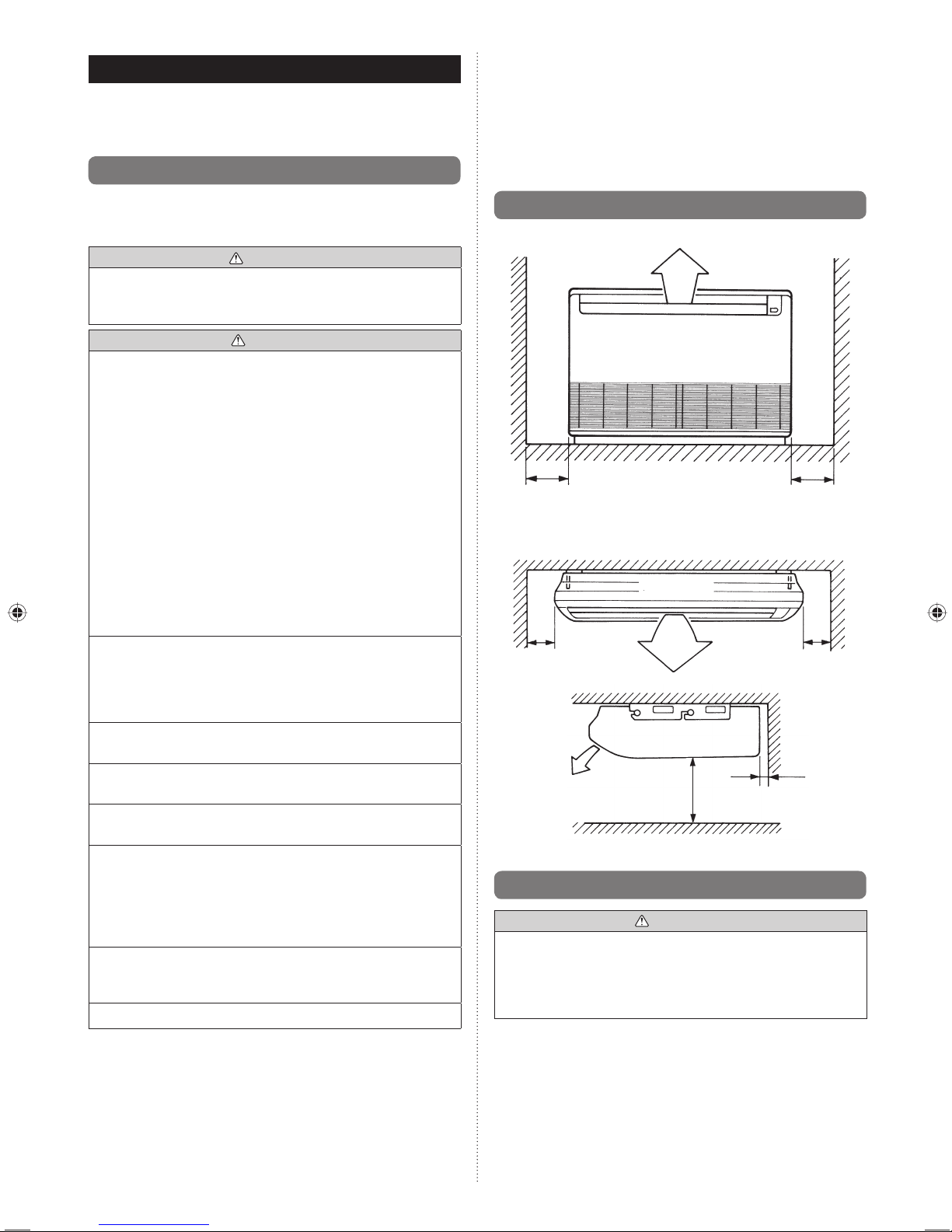
3.2. Installation dimension
Floor console
300
or more
Left Right
Unit : mm
300
or more
Under ceiling
Ceiling
Ceiling
Indoor unit
Left
150
or more
300
or more
2300
or more
Unit : mm
Floor
20 or more
Right
]
1
3.3. Installation the unit
WARNING
• Install the air conditioner in a location which can
withstand a load of at least 5 times the weight of the main
unit and which will not amplify sound or vibration. If the
installation location is not strong enough, the indoor unit
may fall and cause injuries.
Page 5
En-5
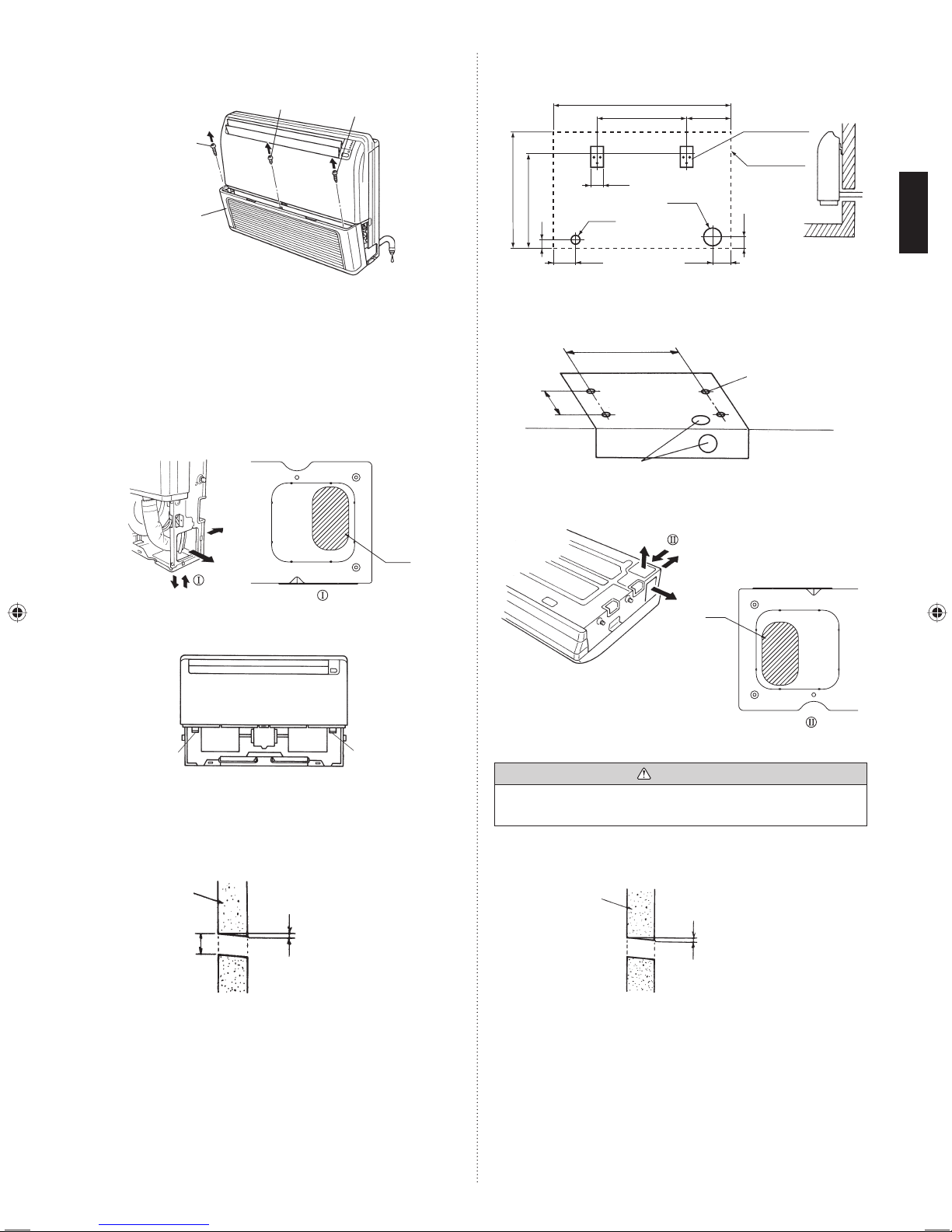
When installing set to wall install the accessory wall bracket at
the position as shown in the fi gure, and mount the set to it.
Unit : mm
Wall bracket
Side of set
990
500
65
655
530
45
65
Ø
50
125 100
Ø
100
245
B. Under ceiling type
Using the installation template, drill holes for piping and
suspension bolts (for holes).
Unit : mm
Installation
template
200
Drilling position
for suspension
bolt
Ceiling
Wall
Drilling position for piping
900
B-1. Drilling for piping
Select piping and drain directions.
To p
Rear
(Install the drain hose
in this direction.)
Right
Hole
VIEW
For direction, bore the oval hole shown in the above fi gure.
CAUTION
• Install the drain hose at the rear; it should not be installed
on the top or right side.
When the directions are selected, drill 80 mm and 50 mm or
150 mm dia. hole on the wall so that the hole is tilted downward toward the outdoor for smooth water fl ow.
Unit : mm
Wall
6
Indoor side Outdoor side
3.3.1. Preparing indoor unit installation
Open the intake grille and remove the 3 screws.
Machine screw
Tapping screw
Tapping screw
Intake grille
Remark : The main unit can be wired before the indoor unit is
installed.
Select the most appropriate installation order.
3.3.2. Indoor unit installation
A. Floor console type
Drilling for piping
Select piping and drain directions.
The piping and drain can be made in 3 directions as shown
below.
VIEW
Hole
For direction, bore the oval hole shown in the above fi gure.
The drain hose can be connected to either the left or right
side.
Drain hose
(Right side)
Drain hose
(Left side)
When the directions are selected, drill a 10 cm dia. hole on
the wall so that the hole is tilted downward toward the outdoor
for smooth water fl ow.
When the pipe is led out from the rear, make a hole as shown
in the fi gure, at the position shown.
Unit : mm
6
100
Wall
Indoor side Outdoor side
Page 6

En-6
B-2. Drilling the holes and attaching the
suspension bolts
Drill Φ25 mm holes at the suspension bolt locations, then
install the bolts.
Bolt Strength 980 to 1470 N (100 to 150 kgf)
ø25 mm
Ceiling panel
20 to 50 mm
[If using anchor bolts]
Drill holes for anchor bolts at the locations at which you will
set the suspension bolts. Note that anchor bolts are M10 bolts
(to be obtained locally).
Anchor-Bolt Strength 980 to 1470 N (100 to 150 kgf)
Ceiling
20 to
50 mm
M10 Anchor bolt
(Field supply)
B-3. Installing Brackets
Install the bracket with nuts, spring washers.
Bracket (Right)
Bracket
Bracket (Left)
Special nut A
(Accessories)
Ceiling panel
Spring washer
(Field supply)
M10 Nut (Field supply)
M10 Nut (Field supply)
B-4. Installing indoor unit
Reset the hex bolts as shown in the fi gure
Unit : mm
Indoor unit
Hex bolt
8 to 13
Apply the indoor unit to the brackets.
Indoor unit
Bolt
Bracket
Now, securely tighten the hex bolts in both sides.
3.3.3. Barrier and RFM base removal and
installation
(1) Remove the barriers by removing the 4 fi xing screws
(2 screws each).
(2) Remove the RFM base by removing the 2 fi xing screws
and unhooking the 1 hook.
(3) After completing the work, install the barriers and RFM
base as they were originally.
RFM base
Fixing screw
(2 positions)
Barriers
Fixing screw
(2 positions)
Hook
Install the barriers in the correct direction.
4. PIPE INSTALLATION
]
CAUTION
• Be more careful that foreign matter (oil, water, etc.) does
not enter the piping than with refrigerant R410A models.
Also, when storing the piping, securely seal the openings
by pinching, taping, etc.
• While welding the pipes, be sure to blow dry nitrogen gas
through them.
]
1
4.1. Selecting the pipe material
CAUTION
• Do not use existing pipes.
• Use pipes that have clean external and internal sides
without any contamination which may cause trouble
during use, such as sulfur, oxide, dust, cutting waste, oil,
or water.
• It is necessary to use seamless copper pipes.
Material : Phosphor deoxidized seamless copper pipes
It is desirable that the amount of residual oil is less than
40 mg/10 m.
• Do not use copper pipes that have a collapsed,
deformed, or discolored portion (especially on the interior
surface). Otherwise, the expansion valve or capillary tube
may become blocked with contaminants.
• Improper pipe selection will degrade performance. As an
air conditioner using R410A incurs pressure higher than
when using conventional refrigerant, it is necessary to
choose adequate materials.
• Thicknesses of copper pipes used with R410A are as shown
in the table.
• Never use copper pipes thinner than those indicated in the
table even if they are available on the market.
Page 7
En-7
Thicknesses of Annealed Copper Pipes (R410A)
Pipe outside diameter [mm (in.)] Thickness [mm]
6.35 (1/4) 0.80
9.52 (3/8) 0.80
12.70 (1/2) 0.80
15.88 (5/8) 1.00
19.05 (3/4) 1.20
1
4.2. Pipe requirement
CAUTION
• Refer to the Installation Manual of the outdoor unit
for description of the length of connecting pipe or for
difference of its elevation.
Use pipe with water-resistant heat insulation.•
CAUTION
• Install heat insulation around both the gas and liquid
pipes. Failure to do so may cause water leaks.
Use heat insulation with heat resistance above 120 °C.
(Reverse cycle model only)
In addition, if the humidity level at the installation location
of the refrigerant piping is expected to exceed 70 %,
install heat insulation around the refrigerant piping.
If the expected humidity level is 70-80 %, use heat
insulation that is 15 mm or thicker and if the expected
humidity exceeds 80 %, use heat insulation that is 20
mm or thicker. If heat insulation is used that is not as
thick as specifi ed, condensation may form on the surface
of the insulation.
In addition, use heat insulation with heat conductivity of
0.045 W/(m·K) or less (at 20 °C).
1
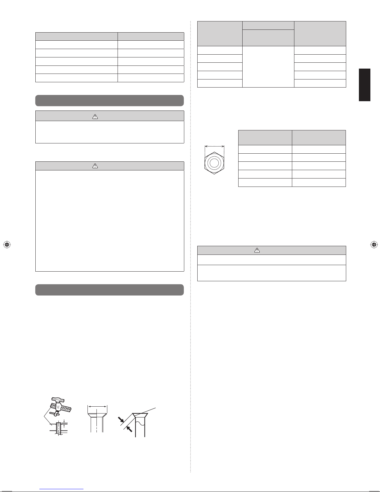
4.3. Flare connection (pipe connection)
4.3.1. Flaring
• Use special pipe cutter and fl are tool exclusive for R410A.
(1) Cut the connection pipe to the necessary length with a
pipe cutter.
(2) Hold the pipe downward so that cuttings will not enter the
pipe and remove any burrs.
(3) Insert the fl are nut (always use the fl are nut attached to
the indoor and outdoor units respectively) onto the pipe
and perform the fl are processing with a fl are tool. Use the
special R410A fl are tool, or the conventional fl are tool.
Leakage of refrigerant may result if other fl are nuts are
used.
(4) Protect the pipes by pinching them or with tape to prevent
dust, dirt, or water from entering the pipes.
L
Check if [L] is fl ared uniformly
and is not cracked or scratched.
Die
Pipe
A
B
Pipe outside
diameter
[mm (in.)]
Dimension A [mm]
Dimension B
-00.4
[mm]
Flare tool for R410A,
clutch type
6.35 (1/4)
0 to 0.5
9.1
9.52 (3/8) 13.2
12.70 (1/2) 16.6
15.88 (5/8) 19.7
19.05 (3/4) 24.0
When using conventional fl are tools to fl are R410A pipes,
the dimension A should be approximately 0.5 mm more
than indicated in the table (for fl aring with R410A fl are tools)
to achieve the specifi ed fl aring. Use a thickness gauge to
measure the dimension A.
Pipe outside
diameter [mm (in.)]
Width across flats
of Flare nut [mm]
6.35 (1/4) 17
9.52 (3/8) 22
12.70 (1/2) 26
15.88 (5/8) 29
19.05 (3/4) 36
4.3.2. Bending pipes
The pipes are shaped by your hands or pipe bender. Be •
careful not to collapse them.
Do not bend the pipes in an angle more than 90°.•
When pipes are repeatedly bend or stretched, the material •
will harden, making it diffi cult to bend or stretch them any
more. Do not bend or stretch the pipes more than 3 times.
CAUTION
• To prevent breaking of the pipe, avoid sharp bends.
• If the pipe is bent repeatedly at the same place, it will
break.
Width across
fl ats
Page 8

En-8
4.3.3. Pipe connection
Connect the silencer pipe to the small (liquid) pipe.
Centering the pipe against port on the indoor unit, turn the
fl are nut with your hand.
Be sure that the small pipe is completely installed before
connecting the large pipe.
Indoor unit side
Silencer pipe
(Accessories)
CAUTION
• Be sure to apply the pipe against the port on the indoor
unit and the outdoor unit correctly. If the centering is
improper, the flare nut cannot be tightened smoothly.
If the flare nut is forced to turn, the threads will be
damaged.
• Do not remove the fl are nut from the indoor unit pipe until
immediately before connecting the connection pipe.
• Do not use mineral oil on flared part. Prevent mineral
oil from getting into the system as this would reduce the
lifetime of the units.
If necessary, cut the silencer pipe and use it.
Silencer pipe
(Accessories)
CAUTION
• Hold the torque wrench at its grip, keeping it in the right
angle with the pipe, in order to tighten the flare nut
correctly.
• Tighten the flare nuts with a torque wrench using the
specified tightening method. Otherwise, the flare nuts
could break after a prolonged period, causing refrigerant
to leak and generate a hazardous gas if the refrigerant
comes into contact with a fl ame.
When the fl are nut is tightened properly by your hand,
hold the body side coupling with a separate spanner, then
tighten with a torque wrench.
Connection pipe
Torque wrench
Indoor unit pipe
(Body side)
Tighten with 2 wrenches.
Holding wrench
Flare nut
Flare nut [mm (in.)] Tightening torque [N·m (kgf·cm)]
6.35 (1/4) dia. 16 to 18 (160 to 180)
9.52 (3/8) dia. 32 to 42 (320 to 420)
12.70 (1/2) dia. 49 to 61 (490 to 610)
15.88 (5/8) dia. 63 to 75 (630 to 750)
19.05 (3/4) dia. 90 to 110 (900 to 1,100)
]
1
4.4. Installing heat insulation
CAUTION
• After checking for gas leaks (refer to the Installation
Manual of the outdoor unit), perform this section.
• Install heat insulation around both the large (gas) and
small (liquid) pipes. Failure to do so may cause water
leaks.
After checking for gas leaks, insulate by wrapping insulation
around the 2 parts (Gas and Liquid) of the indoor unit
coupling, using the coupler heat insulation.
After installing the coupler heat insulation, wrap both ends
with vinyl tape so that there is no gap.
Secure both ends of the heat insulation material using Binder.
And fi nally fi x connection pipe (Liquid) to connection pipe (Gas)
by rolling vinyl tape over coupler heat insulation (Gas) and
coupler heat insulation (Liquid).
Coupler heat
insulation
Indoor unit
No gap
Coupler heat
insulator
(Accessories)
Coupler heat
insulator
(Accessories)
Be sure to overlap
the insulation
Gas pipe Liquid pipe
No gap
Page 9

En-9
Insulation (pipe)
(Accessories)
No gap
Small pipe
Silencer pipe
CAUTION
• There should be no gaps between the insulation and the
unit.
5. INSTALLING DRAIN HOSE
]
CAUTION
• Install the drain hose in accordance with the instructions
in this Installation Manual and keep the area warm
enough to prevent condensation. Problems with the
piping may lead to water leaks.
Use general hard polyvinyl chloride pipe and connect it with
adhesive (polyvinyl chloride) so that there is no leakage.
Always heat insulate the indoor side of the drain hose.
Use a drain pipe that matches the size of the drain hose.
• Do not perform a rise, trap and air bleeding.
• Provide a downward gradient (1/100 or more).
• Provide supporters when long pipes are installed.
• Use an insulation material as needed, to prevent the pipes
from freezing.
• Install the pipes in a way that allows for the removal of the
control box.
O.D.
Drain pipe 32 mm (VP25)
When using the drain port on the left side of the unit, remove
the drain cap and install it to the right side drain port.
(Only when suspended from the ceiling)
Drain cap
Unit
INSTALL THE DRAIN HOSE
Working procedure
1) Install the attached drain hose to the drain port of the
body. Install the hose band from the top of the hose within
the graphic display area. Secure fi rmly with the hose
band.
2) Use vinyl adhesive agent to glue the drain piping (PVC
pipe VP25) which is prepared on site or piping socket.
(Apply color adhesive agent evenly until the gauge line
and seal)
3) Check the drainage.
4) Install the heat insulation.
5) Use the attached heat insulation to insulate the drain port
and band parts of the body.
Top view
Drain hose
(Accessories)
10~15mm
Hose Band
(Accessories)
Soft PVC side
Ensure there is no space
Drain pan
Side view
Applying
area of
adhesive
Hard PVC side
Joint pipe
(Field supply)
Drain pipe (VP25)
(Field supply)
4 mm or less
Wrap the Drain hose insulation around the drain hose
connection.
Top view
Drain pan
Drain hose
100mm
Drain hose insulation
(Accessories)
Hose opening view
Wind the attached heat insulation
around the hose band. Make sure
the alignment is on top.
A. Floor console type
Be sure to arrange the drain hose so that it is leveled lower
than the drain hose connecting port of the indoor unit.
Drain hose
OK NO GOOD NO GOOD
Arrange the drain
hose lower than
this portion.
CAUTION
• Do not install the unit so that the drain hose side is too
high. Height A should be less than 5 mm.
Drain hose
NO GOOD NO GOOD
Page 10

En-10
B. Under ceiling type
Be sure to arrange the drain hose so that it is leveled lower
than the drain hose connecting port of the indoor unit.
Drain
hose
Arrange the drain hose
lower than this portion.
OK NO GOOD
When drain hose is arranged backward.
Secure the drain hose with the VT wire.
Drain hose
VT wire
hole
VT wire
Pass the drain hose
through here.
Cut the grille
Intake grille
Base (Bottom)
6. ELECTRICAL WIRING
]
WARNING
• Electrical work must be performed in accordance with this
Manual by a person certifi ed under the national or regional
regulations. Be sure to use a dedicated circuit for the unit.
An insufficient power supply circuit or improperly
performed electrical work can cause serious accidents
such as electric shock or fi re.
• Before starting work, check that power is not being
supplied to the indoor unit and outdoor unit.
• Use the included connection cables and power cables
or ones specified by the manufacturer. Improper
connections, insufficient insulation, or exceeding the
allowable current can cause electric shock or fi re.
• For wiring, use the prescribed type of cables, connect
them securely, making sure that there are no external
forces of the cables applied to the terminal connections.
Improperly connected or secured cables can cause
serious accidents such as overheating the terminals,
electric shock, or fi re.
• Do not modify the power cables, use extension cables,
or use any branches in the wiring. Improper connections,
insuffi cient insulation, or exceeding the allowable current
can cause electric shock or fi re.
• Match the terminal board numbers and connection cable
colors with those of the outdoor unit. Erroneous wiring
may cause burning of the electric parts.
• Securely connect the connection cables to the terminal
board. In addition, secure the cables with wiring holders.
Improper connections, either in the wiring or at the ends
of the wiring, can cause a malfunction, electric shock, or
fi re.
• Always fasten the outside covering of the connection
cable with the cable clamp. (If the insulator is chafed,
electric leakage may occur.)
• Securely install the electrical box cover on the unit.
An improperly installed electrical box cover can cause
serious accidents such as electric shock or fi re through
exposure to dust or water.
• Install sleeves into any holes made in the walls for wiring.
Otherwise, a short circuit could result.
• Install a ground leakage breaker. In addition, install the
ground leakage breaker so that the entire AC main power
supply is cut off at the same time. Otherwise, electric
shock or fi re could result.
• Always connect the ground cable.
Improper grounding work can cause electric shocks.
• Install the remote controller cables so as not to be direct
touched with your hand.
• Perform wiring work in accordance with standards so that
the air conditioner can be operated safely and positively.
• Connect the connection cable fi rmly to the terminal
board. Imperfect installation may cause a fi re.
CAUTION
• Ground the unit.
Do not connect the ground cable to a gas pipe, water
pipe, lightning rod, or a telephone ground cable.
Improper grounding may cause electric shock.
• Do not connect power supply cables to the transmission
or remote controller terminals, as this will damage the
product.
• Never bundle the power supply cable and transmission
cable, remote controller cable together.
Separate these cable by 50 mm or more.
Bundling these cables together will cause miss operation
or breakdown.
• When handling PCB, static electricity charged in the body
may cause malfunction of the PCB. Follow the cautions
below:
• Establish a ground for the indoor and outdoor units and
peripheral devices.
• Cut power (breaker) off.
• Touch metal part of the indoor and outdoor units for
more than 10 seconds to discharge static electricity
charged in the body.
• Do not touch terminals of parts and patterns
implemented on PCB.
Page 11

En-11
]
1
6.1. Electrical requirement
Voltage rating
230 V
Operating range
198 - 264 V
Recom-
mended cable
size (mm2)
Cable type Remark
Power
supply cable
2.5
Type245 IEC57
or equivalent
1ø 50 Hz
198 - 264 V
2 Cable + ground
Transmission
cable
0.33
LONWORKS
compatible cable
22 AWG
LEVEL 4 (NEMA)
non-polar 2 core,
twisted pair solid
core diameter
0.65 mm
Remote
controller
cable
0.33
Sheathed
PVC cable*
Polar 3 core
Twisted pair
*: Use shielded cable in accordance with local rules for
remote controller cable.
Fuse capacity (A) Breaker for leakage current
15 30 mA 0.1 sec. or less
]
1
6.2. Wiring method
(EXAMPLE)
POWER SUPPLY
OUTDOOR UNIT
BREAKER
POWER SUPPLY
TRANSMISSION
TRANSMISSION
POWER
SUPPLY
POWER
SUPPLY
REMOTE
CONTROLLER
(Primary)
REMOTE
CONTROLLER
POWER
SUPPLY
REMOTE
CONTROL
TRANSMISSION TRANSMISSION
POWER
SUPPLY
POWER
SUPPLY
REMOTE
CONTROL
REMOTE
CONTROL
INDOOR UNIT
POWER
SUPPLY
REMOTE
CONTROLLER
(Secondary)
INDOOR UNIT
INDOOR UNIT
BREAKER
BREAKER BREAKER
*Ground the remote controller if it has a ground wire.
]
1
6.3. Unit wiring
• Before attaching the cable to terminal block.
6.3.1. Power supply cable
Power supply
cable
15 mm
Earth
cable
70 mm
A. For solid core wiring
(1) To connect the electrical terminal, follow the below
diagram and connect after looping it around the end of the
cable.
(2) Use the specifi ed cables, connect them securely, and
fasten them so that there is no stress placed on the
terminals.
(3) Use an appropriate screwdriver to tighten the terminal
screws. Do not use a screwdriver that is too small,
otherwise, the screw heads may be damaged and prevent
the screws from being properly tightened.
(4) Do not tighten the terminal screws too much, otherwise,
the screws may break.
(5) See the table for the terminal screw tightening torques.
(6) Please do not fi x 2 power supply cables with 1 screw.
Strip 25 mm
Loop
Screw with
special washer
Cable
Cable end (Loop)
Terminal block
Screw with
special
washer
Cable end
(Loop)
Cable
WARNING
• When using solid core cables, do not use the ring
terminal. If you use the solid core cables with the ring
terminal, the ring terminal’s pressure bonding may
malfunction and cause the cables to abnormally heat up.
Page 12

En-12
6.3.2. Transmission and Remote controller cable
Transmission cable
Shielded
cable
(No fi lm)
50 mm
30 mm
Remote controller cable
30 mm
• Connect remote controller and transmission cables as shown
in Fig. B.
• When the 2 cables are attached.
Fig. B
Different
diameter
Connect to
1 side
OK
NO GOOD NO GOOD
WARNING
• Tighten the terminal screws to the specified torques,
otherwise, abnormal overheating may be produced and
possibly cause heavy damage inside the unit.
Tightening torque
M3 screw
(Transmission/X1, X2)
(Remote controller/Y1, Y2, Y3)
0.5 to 0.6 N·m
(5 to 6 kgf·cm)
CAUTION
• To peel the fi lm from the lead cable, use a dedicated tool
that will not damage the conductor cable.
• When installing a screw on the terminal block, do not cut
the cable by overtightening the screw. On the other hand,
an undertightened screw can cause faulty contact, which
will lead to a communication failure.
]
B. For strand wiring
(1) Use ring terminals with insulating sleeves as shown in the
fi gure below to connect to the terminal block.
(2) Securely clamp the ring terminals to the cables using an
appropriate tool so that the cables do not come loose.
(3) Use the specifi ed cables, connect them securely, and
fasten them so that there is no stress placed on the
terminals.
(4) Use an appropriate screwdriver to tighten the terminal
screws. Do not use a screwdriver that is too small,
otherwise, the screw heads may be damaged and prevent
the screws from being properly tightened.
(5) Do not tighten the terminal screws too much, otherwise,
the screws may break.
(6) See the table for the terminal screw tightening torques.
(7) Please do not fi x 2 power supply cables with 1 screw.
Ring terminal
Sleeve
Screw with
special washer
Cable
Ring terminal
Terminal block
Screw with
special
washer
Cable
Ring
terminal
Strip 10 mm
WARNING
• Use ring terminals and tighten the terminal screws to the
specifi ed torques, otherwise, abnormal overheating may
be produced and possibly cause heavy damage inside
the unit.
Tightening torque
M4 screw
(Power supply/L, N, GND)
1.2 to 1.8 N·m
(12 to 18 kgf·cm)
Page 13

En-13
1
6.4. Connection of wiring
(1) Remove the electric component box.
Electric component box
Electric component box
RFM
CAUTION
• Do not remove the RFM fixing screws. If the stays are
removed, the electric component box will fall.
• If you use as “Floor console”, you must remove screws
and RFMs (2 position).
When removing the electric component box, remove the
clamp from the cables.
After completing the work, fasten the cables as they were
originally by installing the clamp.
Cables
Clamp
Remove the clamp.
Install the clamp.
(2) Pull out the electric component box.
Electric component box
(3) Remove the electric component box cover.
Remove the 3 tapping screws.
Electric component box cover
Base
CAUTION
• Be careful not to pinch the lead cables between the
electric component box and base.
(4) Wiring
* When there is 1 transmission cable or remote controller
cable, fasten it the same way as shown in the fi gure with a
binder (medium).
Binder (Medium)
(Accessories)
L, N: Power supply cable
Remote controller cable
Y1: Red, Y2: White, Y3: Black
X1, X2: Transmission cable
]
1
6.5. External input and external output
(Optional parts)
Controller PCB
Input No Voltage terminal (CN17)
Input Voltage terminal (CN6)
Output terminal (CN16)
GND
Page 14

En-14
(1) External input terminals
• Indoor unit can be Start/Stop or Emergency stop, Forced
stop by using indoor unit PCB CN6 or CN17.
Wiring methods and specifi cations
• A twisted pair cable (22AWG) should be used. Maximum
length of cable is 150 m.
* Use an external input and output cable with appropriate
external dimension, depending on the number of cables to
be installed.
• The wire connection should be separate from the power
cable line.
• Input selection
Use either one of these types of terminal according to the
application. (Both types of terminals cannot be used
simultaneously.)
• Voltage terminal ([CN6])
When a power supply must be provided at the input device
you want to connect, use the voltage terminal ([CN6]).
1
2
3
+
+
-
-
-
Input device 1Input device 2
Load
resistance
Load
resistance
*1
DC power supply
12 - 24V
connected unit
*a
*a
P.C .B
CN6
*b
*1 Make the power supply DC12 to 24V. Select a power supply
capacity with an ample surplus for the connected load.
Do not impress a voltage exceeding 24V across pins 1-2, and
1-3.
*a The allowable current is DC5~10mA. (Recommended:
DC5mA)
Provide a load resistance such that the current becomes
DC10mA or less.
Select very low current use contacts (usable at DC12V,
DC1mA or less).
*b The polarity is [+] for pin 1 and [-] for pin 2 and 3.
Connect correctly.
When connected to voltage terminals of multiple indoor units
with a connected unit, be sure to make a branch outside the
indoor unit using a pull box, etc. as shown on below example.
DC power
supply 12-24V
connected unit
Load
resistance
P.C .B
P.C .B
CN6
CN6
CN6
P.C .B
Input device 1Input device 2
Indoor unitIndoor unitIndoor unit
Load
resistance
• No voltage terminal ([CN17])
When a power supply is unnecessary at the input device you
want to connect, use the no voltage terminal ([CN17]).
1
2
3
P.C .B
GND
Ch 1
*c
*c
*d
Ch 2
CN17
connected unit
*c Select very low current use contacts (usable at DC12V,
DC1mA or less).
*d The wiring is different from voltage terminals. Be suffi ciently
careful when wiring.
When connected to no voltage terminals of multiple indoor
units with a connected unit, insulate each indoor unit with
relay, etc. as shown on below example.
When connected to multiple indoor units directly, it will cause
breakdown.
Power supply for relay
Indoor unit Indoor unit Indoor unit
Input device 2
Input device 1
K1~ K6: Re lay
P.C .B
K1
P.C .B
P.C .B
CN17
CN17
CN17
K2
K3
K4
K5
K6
Operation behavior
• Input signal type
The input signal type can be selected.
Pulse
Edge
The width of pulse
must be longer than
200msec.
It is switched by Dip-sw on the indoor
unit PCB.
Dip-sw [Set 2-2] Input signal type
OFF Edge
ON Pulse
• When function setting is “Start/Stop” mode
In the case of “Edge” input
Connector Input signal Command
Ch1 of
CN6 or CN17
OFF → ON Operation
ON → OFF Stop
In the case of “Pulse” input
Connector Input signal Command
CN6 or CN17
Ch1 OFF → ON Operation
Ch2 OFF → ON Stop
(Device for DC Current)
Page 15

En-15
* The last command has priority.
* The indoor units within the same remote controller group
operates in the same mode.
• When function setting is “Emergency stop” mode
In the case of “Edge” input
Connector Input signal Command
Ch1 of
CN6 or CN17
OFF → ON Emergency stop
ON → OFF Normal
In the case of “Pulse” input
Connector Input signal Command
CN6 or CN17
Ch1 OFF → ON
Emergency
stop
Ch2 OFF → ON Normal
* All indoor units of same refrigerant system stops when
Emergency stop operates.
• When function setting is “Forced stop” mode
In the case of “Edge” input
Connector Input signal Command
Ch1 of
CN6 or CN17
OFF → ON Forced stop
ON → OFF Normal
In the case of “Pulse” input
Connector Input signal Command
CN6 or CN17
Ch1 OFF → ON Forced stop
Ch2 OFF → ON Normal
* When the forced stop is triggered, indoor unit stops and
Start/Stop operation by a remote controller is restricted.
* When forced stop function is used with forming a
remote controller group, connect the same equipment
to each indoor unit within the group.
• Selection method of functions
“Start/Stop” mode or “Emergency stop” mode, “Forced stop”
mode can be selected with function setting of indoor unit.
(2) External output terminals
• When picking up output signals for operating status,
abnormal conditions or indoor unit status.
Wiring methods and specifi cations
1
2
3
4
P.C .B
CN16
*4
+
+
-
-
-
-
DC power supply
12 - 24V *2
Connected load
*3
connected unit
Connected load
*3
Connected load
*3
*2 Provide a DC12 to 24V power supply. Select a power
supply capacity with an ample surplus for the connected
load.
*3 The allowable current is 30mA or less. Provide a load
resistance such that the current becomes 30mA or less.
*4
Polarity is [+] for pin 1 and [-] for pins 2-4. Connect correctly.
Do not impress a voltage exceeding 24V across pins 1-2, 1-3,
and 1-4.
Operation behavior
Connector Output voltage Status
CN16
External
output1
Pins 1-2
0V Stop
DC 12-24 V *2 Operation
External
output2
Pins 1-3
0V Normal
DC 12-24 V *2 Error
External
output3
Pins 1-4
0V Indoor unit fan stop
DC 12-24 V *2
Indoor unit fan
operation
A twisted pair cable (22AWG) should be used. Maximum
length of cable is 150 m.
* Use an external input and output cable with appropriate
external dimension, depending on the number of cables to
be installed.
Page 16

En-16
(3) Connection methods
• Wire modifi cation
Use a tool to cut off the terminal on the end of the wire, and
then remove the insulation from the cut end of the wire.
Connect the wire with connecting wire with solder.
Important: Be sure to insulate the connection between the
wires.
Option parts
External input /output wire
Insulated connection
Field supply
Input Voltage terminal
(CN6)
Controller PCB
Input No Voltage terminal (CN17)
Output terminal (CN16)
Binder
Switch PCB
Controller PCB
Power supply PCB
Terminal PCB
7. FIELD SETTING
There are 3 methods for address setting by FIELD SETTING
as follows.
Set by either of the methods.
Each setting method is described (1) to (3) below.
(1)
IU AD, REF AD SW settings
....This section (7.1. Setting
the address)
(2) Remote controller settings .... Refer to the wired or
wireless remote controller
manual for detailed setting
information. (Set IU AD,
REF AD SW to 0)
(3) Automatic address settings ... Refer to the outdoor unit
manual for detailed setting
information. (Set IU AD,
REF AD SW to 0)
]1
7.1. Setting the address
Manual address setting method
• The indoor unit address and the refrigerant circuit address
can also be set up through the wireless remote controller.
CAUTION
• Be sure to turn OFF the power before performing the
fi eld setting.
• Set it according to the following procedures when setting
manually.
It can be set manually if the cover (small) is removed under
the condition that the electric component box cover is
attached.
Cover (small)
Electric component box
Rotary switch
Example: “0”
Rotary switch
Example: “0”
Page 17

En-17
CAUTION
• Use an insulated screwdriver to set the dip switches.
Setting
Setting
range
Type of switch
Indoor unit
address
0–63
Setting
example
2
IU AD x 10 IU AD x 1
Refrigerant
circuit
address
0–99
Setting
example
63
REF AD x 10 REF AD x 1
(1) Indoor unit address
Rotary switch (IU AD × 1) .........Factory setting “0”
Rotary switch (IU AD × 10) .......Factory setting “0”
When connecting multiple indoor units to 1 refrigerant sys-
tem, set the address at IU AD SW as shown in the Table A.
(2) Refrigerant circuit address
Rotary switch (REF AD × 1) .....Factory setting “0”
Rotary switch (REF AD × 10) ...Factory setting “0”
In the case of multiple refrigerant systems, set REF AD
SW as shown in the Table A for each refrigerant
system.
Set to the same refrigerant circuit address as the outdoor
unit.
Table A
Address
Rotary
Switch Setting
Address
Rotary
Switch Setting
Refrigerant
circuit
REF AD SW
Indoor unit
IU AD SW
×
10
×
1
×
10
×
1
000000
101101
202202
303303
404404
505505
606606
707707
808808
909909
10 1 0 10 1 0
11 1 1 11 1 1
12 1 2 12 1 2
.
.
.
.
.
.
.
.
.
.
.
.
.
.
.
.
.
.
99 9 9 63 6 3
Do no
t set the indoor unit address (IU AD SW) at 64 to 99. It
may result
failure.
(3) Remote controller address
Rotary switch (RC AD SW)....Factory setting “0”
When connecting multiple indoor units to 1 standard wired
remote controller, set the address at RC AD SW in
sequence from 0.
Setting
Setting
range
Type of switch
Remote con-
troller
address
0–15
Setting
example
0
RC AD
Example If 4 indoor units are connected.
Remote
controller
Indoor unit
Indoor unit
Indoor unitIndoor unit
RC AD SW0RC AD SW1RC AD SW2RC AD SW
3
RC AD SW
01234567
Address 01234567
RC AD SW
89ABCDEF
Address 8 9 10 11 12 13 14 15
]1
7.2. Custom code setting
Selecting the custom code prevents the indoor unit mix-up.
(Fig. B)
(Up to 4 codes can be set.)
Perform the setting for both the indoor unit and the remote
controller.
Fig. B
Code change
Indoor unit
Remote
controller
Confusion
A B C D
A B C D
• Custom code setting for indoor unit
Set the DIP SW SET 3 SW1, SW2, referring to the Table B.
sw1sw2sw3sw
4
Dip switch
“SET 3”
ON
OFF
Table B
Custom code
A (Factory setting) B C D
DIP SW
SET 3 SW1
OFF ON OFF ON
DIP SW
SET 3 SW2
OFF OFF ON ON
Page 18

En-18
]1
7.3. Function setting
• FUNCTION SETTING can be performed with the wired or
wireless remote controller.
(The remote controller is optional equipment)
• Refer to the wired or wireless remote controller manual for
detailed setting information. (Set IU AD, REF AD SW to 0)
• Refer to “7.1. Setting the address” for indoor unit address
and refrigerant circuit address settings.
•
Turn the power of the indoor unit ON before starting the setting.
* Turning on the power indoor units initializes EEV, so make
sure the piping air tight test and vacuuming have been
conducted before turning on the power.
* Also check again to make sure no wiring mistakes were
made before turning on the power.
Function details
Function
Function
number
Setting
number
Default Details
Filter
indicator
interval
11
00 Default
○
Adjust the fi lter cleaning interval
notifi cation. If the notifi cation is
too early, change to setting 01. If
the notifi cation is too late, change
to setting 02.
01 Longer
02 Shorter
Filter
indicator
action
13
00 Enable
○
Enable or disable the fi lter
indicator. Setting 02 is for use
with a central remote controller.
01 Disable
02
Display
only on
central
remote
controller
Horizon-
tal swing
airfl ow
direction
24
00 Default
○
Adjust the horizontal swing airfl ow
direction.
(For horizontal swing equipped
models)
01 Left half
02 Right half
Cool air
tem-
perature
trigger
30
00 Default
○
Adjust the cool air trigger
temperature. To lower the trigger
temperature, use setting 01. To
raise the trigger temperature, use
setting 02.
01 Adjust (1)
02 Adjust (2)
Hot air
tem-
perature
trigger
31
00 Default
○
Adjust the hot air trigger
temperature. To lower the trigger
temperature by 6 degrees C, use
setting 01. To lower the trigger
temperature by 4 degrees C, use
setting 02. To raise the trigger
temperature, use setting 03.
01 Adjust (1)
02 Adjust (2)
03 Adjust (3)
Auto
restart
40
00 Enable
Enable or disable automatic
system restart after a power outage.
*
Auto restart is an emergency function such as for power failure etc.
Do not start and stop the indoor
unit by this function in normal
operation.
Be sure to operate by the control
unit, converter or external input
device.
01 Disable
○
External
control
46
00 Start/Stop
○
Allow an external controller to
start or stop the system, or to
perform an emergency stop.
* If an emergency stop is
performed from an external
controller, all refrigerant systems
will be disabled.
*
If forced stop is set, indoor unit
stops
by the input to the external
input terminals, and Start/Stop by
a remot
e controller is restricted.
01
Emergency
stop
02
Forced
stop
Error
report
target
47
00 All
○
Change the target for reporting
errors. Errors can either be
reported in all locations, or only
on the central remote controller.
01
Display only
on central
remote controller
7.3.1. Button name and function
OPERATION indicator lamp (Green)
TIMER indicator lamp (Orange)
FILTER indicator lamp (Red)
MANUAL AUTO button
7.3.2. Checking the function settings
• Press and hold the “MANUAL AUTO” button on the indoor
unit for 3 seconds to check the function settings. It is
necessary to disconnect the power in order to return to
normal operation mode.
(1) Indoor unit and refrigerant address indication
Indication pattern
Indicator name
Indication pattern
Indoor unit
address
Refrigerant address
OPERATION
indicator lamp (Green)
ON
Flash
(1.0s ON/1.0s OFF)
TIMER indicator lamp
(Orange)
Address: tens place (0.5s ON/0.5s OFF)
FILTER indicator lamp
(Red)
Address: ones place (0.5s ON/0.5s OFF)
• Indoor unit address example
(Example) ADDRESS : 24
OPERATION
indicator lamp
(Green)
TIMER
indicator lamp
(Orange)
FILTER
indicator lamp
(Red)
10 sec
1 cycle 12 sec
8 sec
ON
OFF
0.5s
0.5s 0.5s 0.5s
0.5s
0.5s
0.5s 0.5s
0.5s
0.5s
0.5s 0.5s
ON
OFF
ON
OFF
ON
Page 19

En-19
• Refrigerant address example
(Example) ADDRESS : 30
OPERATION
indicator lamp
(Green)
TIMER
indicator lamp
(Orange)
FILTER
indicator lamp
(Red)
9 sec
1 cycle 12 sec
ON
OFF
1.0s 1.0s 1.0s
1.0s 1.0s 1.0s 1.0s
0.5s
0.5s
0.5s 0.5s 0.5s 0.5s
ON
OFF
ON
OFF
OFF
• Setting details
Function
number
Item Setting number
01 Indoor unit address 00~63
02 Refrigeration address 00~99
For use with a remote controller, set all rotary switches to 0,
and refer to “7.1. Setting the address” for details.
All switches are set to 0 at the factory.
(2) Others
Indication pattern
Indicator Name Indication pattern
OPERATION
indicator lamp (Green)
Function number; tens place
(0.5s ON/0.5s OFF)
TIMER
indicator lamp (Orange)
Function number; ones place (0.5s
ON/0.5s OFF)
FILTER
indicator lamp (Red)
Setting number: (0 - 9) (0.5s ON/0.5s
OFF)
(Example) Function : 31, Setting number : 2
OPERATION
indicator lamp
(Green)
TIMER
indicator lamp
(Orange)
FILTER
indicator lamp
(Red)
11 sec
10 sec
9 sec
1 cycle 12 sec
ON
OFF
0.5s
0.5s
0.5s
0.5s
0.5s
0.5s
0.5s
0.5s
0.5s
0.5s 0.5s 0.5s
ON
OFF
ON
OFF
8. MOUNT THE COVER PLATE AND
THE INTAKE GRILLE
]
1
8.1. Handling for the pipe take-off part
When the pipe is pulled out in the direction shown in the fi gure
below, cover the take-off part with material (putty or the like)
that will block it off.
UNDER CEILING TYPE
To p
Right
Rear
FLOOR CONSOLE TYPE
]
1
8.2. Mount the cover plate (Right)
(1) Cut a pipe exit hole in the right plate. This is only when
the pipe exits from the right side. (This operation is not
required when the protrusion is on the top or rear.)
Cover plate (Right) (Accessories)
Page 20

En-20
(2) Join the cover plates (right) and mount with screws.
Tapping screw (ø4 × 10)
(Accessories)
]
1
8.3. Mount the cover plate (Left)
(1) Join the cover plates (left) and mount with screws.
Tapping screw (ø4 × 10)
(Accessories)
Cover plate (Left)
(Accessories)
8.4. Mount the intake grille
(1) Cut the right side of the intake grille. This is only when the
pipe exits from the right side.
(2) Insert the hinges on the bottom of the intake grille into the
holes in the base assembly. Then mount the arms to the
3 areas on the top of the intake grille.
9. TEST OPERATION
]
1
9.1. Test operation using PCB (Outdoor
unit)
• Refer to the Installation Manual for the outdoor unit if the
PCB for the outdoor unit is to be used for the test operation.
]
1
9.2. Test operation using remote controller
• Refer to the Installation Manual for the remote controller to
perform the test operation using the remote controller.
• When the air conditioner is being test run, the OPERATION
and TIMER indicator lamps fl ash slowly at the same time.
10. CHECK LIST
]1
Pay special attention to the check items below when
installing the indoor unit(s). After installation is complete, be
sure to check the following check items again.
Check items
If not performed
correctly
Check
box
Has the indoor unit
been installed correctly?
Vibration, noise,
indoor unit may drop
Has there been a
check for gas leaks
(refrigerant pipes)?
No cooling, No heating
Has heat insulation
work been completed?
Water leakage
Does water drain easily
from the indoor units?
Water leakage
Is the voltage of the
power source the same
as that indicated on the
label on the indoor unit?
No operation, heat
or burn damage
Are the wires and
pipes all connected
completely?
No operation, heat
or burn damage
Is the indoor unit
grounded?
Short circuit
Is the connection cable
the specifi ed thickness?
No operation, heat
or burn damage
Are the inlets and outlets
free of any obstacles?
No cooling, No heating
Does start and stop air
conditioner operation
by remote controller
or external device?
No operation
After installation is
completed, has the
proper operation
and handling been
explained to the user?
Page 21

En-21
11. ERROR CODES
1
If you use a wired type remote controller, error codes will
appear on the remote controller display. If you use a wireless
remote controller, the lamp on the photodetector unit will
output error codes by way of blinking patterns. See the lamp
blinking patterns and error codes in the table below.
Error display
Wired
Remote
Controller
Error CODE
Error contents
OPERATIOR
indicator
lamp
(green)
TIMER
indicator
lamp
(orange)
FILTER
indicator
lamp
(red)
(1) (2)
Remote
controller
communication
error
(1) (4)
Anomalous
network
communications
(1) (6)
Parallel
communication
error
(3) (1)
Power
frequency error
(3) (2)
Model
information
error/EEPROM
accession error
(4) (1)
Room
temperature
thermistor error
(4) (2)
Indoor heat
exchanger
temperature
thermistor error
(5) (1)
Indoor fan
motor error
(5) (3) Drainage error
(9) (15)
Outdoor unit
error
Display mode
: 0.5s ON / 0.5s OFF
: 0.1s ON / 0.1s OFF
( ) : Number of fl ashing
Wired Remote Controller Display
Error code
 Loading...