

Fujitsu AUUA9TLAV, AUUA24TLAV, AUUA18TLAV, AUUA7TLAV, AUUB18TLAV Service Manual
...
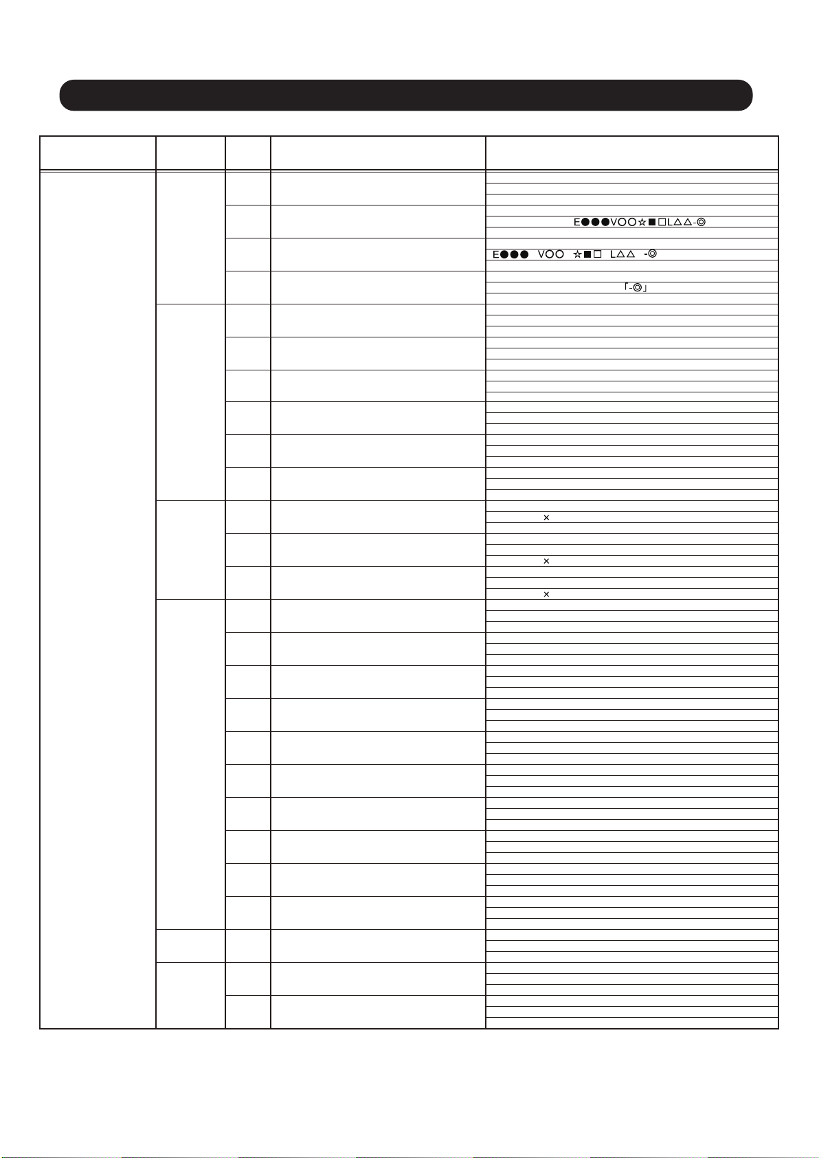
SERVICE MANUAL
208/230V 60Hz

1. TEST RUN
CONTENTS
1-1 EXECUTION PROCEDURE AND EXECUTION PRECAUTIONS.............................
1-2 CHECK ITEMS BEFORE POWER ON.......................................................................
1-2-1 Power source inspection......................................................................................
1-2-2 Outdoor unit field setting inspection.....................................................................
1-2-3 Indoor unit field setting inspection.....................................................................
1-2-4 RB unit field setting inspection.............................................................................
1-2-5 Transmission wire installation inspection............................................................. 01-06
1-2-6 Piping installation
1-2-7 Refrigerant charge amount inspection................................................................. 01-11
1-2-8 3-way valve opening inspection........................................................................... 01-11
1-3 CHECK ITEMS AFTER POWER ON.........................................................................
1-3-1 Power source check...........................................
1-3-2 Error indication check..........................................................................................
1-3-3 Installed unit and their addresses check......................................................
1-3-4 Transmission line connection check.....................................................................
1-3-5 Operation check sheet.......................................................................................... 01-15
1-4 TEST RUN OPERATION........................................................................................... 01-16
1-4-1 Test Run from outdoor unit PC board................................................................
1-4-2 Test Run From remote controller.......................................................................
1-5 TEST RUN CONTROL...............................................................................................
1-6 FIELD SETTING / FUNCTION SETTING FOR OUTOOR UNIT................................
1-7 FIELD SETTING / FUNCTION SETTING FOR INOOR UNIT....................................
1-8 FIELD SETTING / FUNCTION SETTING FOR OUTDOOR AIR UNIT......................
inspection................................................................................ 01-09
.................................................
01-01
01-03
01-03
01-04
... 01-04
01-05
01-12
01-12
01-12
........ 01-13
01-14
01-16
01-17
01-20
01-21
01-25
01-26
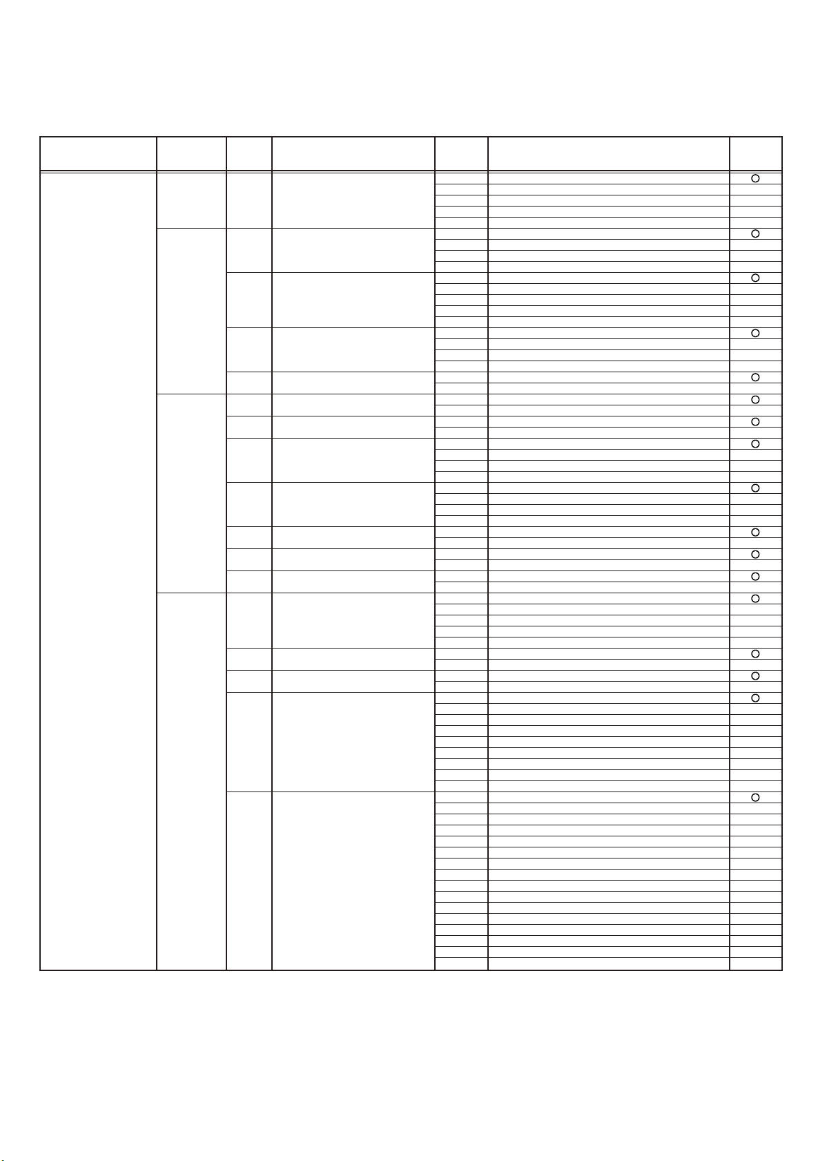
2. OUTDOOR UNIT OPERATION CONTROL
2-1 REFRIGERANT CIRCUIT..........................................................................................
2-1-1 Refrigerant circuit for Outdoor air unit.................................................................
2-2 INPUT / OUTPUT LIST...............................................................................................
2-3 HEAT RECOVERY OPERATION CONTROL............................................................ 02-03
2-3-1 Operation mode selection and controlling...........................................................
2-4 COMPRESSOR OPERATION.................................................................................... 02-03
2-4-1 Operation / Stop Condition..................................................................................
2-4-2 Compressor speed control..................................................................................
3 Capacity control...................................................................................................
2-4-
2-4-4 Compressor Sequence Operation.......................................................................
2-5 HEAT EXCHANGER CONTROL................................................................................
2-5-1 Operation mode selection and controlling...........................................................
2-5-2 Capacity control...................................................................................................
2-6 FAN CONTROL..........................................................................................................
2-6-1 Cooling / Cooling main operation........................................................................
2-6-2 Heating / Heating main operation........................................................................
2-7 EXPANSION VALVE CONTROL...............................................................................
2-8 SPECIAL OPERATION...............................................................................................
2-8-1 Oil Recovery Operation.......................................................................................
2-8-2 Pre-Heat Operation.............................................................................................
2-8-3 Defrost Operation Control.................................
2-8-4 Low noise mode...................................................................................................
2-8-5 Snow Falling Protection Fan Mode -Default Setting -..........................................
...................................................
02-01
02-01
02-02
02-03
02-03
02-04
02-05
02-06
02-07
02-07
02-07
02-08
02-08
02-09
02-10
02-11
02-11
02-11
02-12
02-14
02-15
+1

CONTENTS
2-9 PROTECTIVE FUNCTION........................................................................................
2-9-1 Discharge temperature protection.......................................................................
2-9-2 High pressure protection......................................................................................
2-9-3 Low pressure protection......................................................................................
2-9-4 Heatsink temperature protection.........................................................................
2-9-5 Compressor temperature protection....................................................................
2-9-6 O.U Heat - Ex.1(2) Gas Temp. abnormal stop....................................................
2-9-7 Over current protection........................................................................................
2-9-8 Compressor Frequency Maximum setting protection..........................................
2-9-9 Compressor compress ratio protection................................................................
2-9-10 Fan Motor, Motor Driver abnormal stop protection............................................
2-9-11 EEV Coil abnormal Stop....................................................................................
3. INDOOR UNIT AND RB UNIT OPERATION
3-1 FAN CONTROL..........................................................................................................
3-1-1 Fan Speed Setting...............................................................................................
3-1-2 "AUTO" Position...................................................................................................
3-2 MASTER CONTROL..................................................................................................
02-16
02-16
02-18
02-20
02-21
02-21
02-21
02-22
02-22
02-22
02-23
02-23
03-01
03-01
03-01
03-02
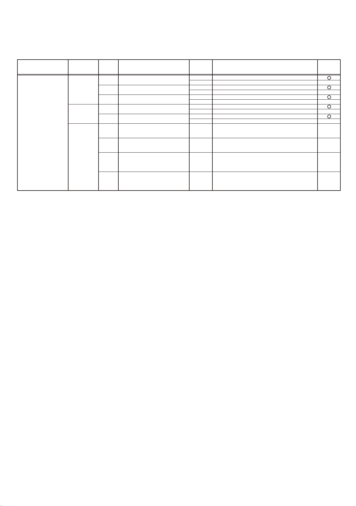
3-2-1 Operation Mode Control.......................................................................................
3-2-2 Auto Changeover Heating / Cooling Operation....................................................
3-2-3 Auto Changeover Cooling / Dry Operation..........................................................
3-2-4 Custom auto Heating / Cooling Operation ..........................................................
3-2-5 "COOL" Position..................................................................................................
3-2-6 "HEAT" Position..................................................................................................
3-3 LOUVER CONTROL..................................................................................................
3-4 ELECTRONIC EXPANSION VALVE CONTROL......................................................
3-5 DRAIN PUMP OPERATION.......................................................................................
3-6 FUNCTION..................................................................................................................
3-6-1 Auto Restart.........................................................................................................
3-6-2 Freeze Prevention Control...................................................................................
3-6-3 Oil Recovery Operation / Defrost Operation .......................................................
3-6-4 Outdoor temperature protected operation for Outdoor air unit ............................
3-7 RB UNIT COMPONENT.............................................................................................
3-7-1 Position of Solenoid coil.......................................................................................
3-7-2 Position of Solenoid valve.................................................................................... 03-13
3-7-3 PCBs layout......................................................................................................... 03-14
3-7-4 PCB component.................................................................................................. 03-14
3-7-5 Solenoid Valve controlling................................................................................... 03-15
3-7-6 Refrigerant Flow.................................................................................................. 03-15
03-02
03-04
03-05
03-06
03-07
03-07
03-08
03-11
03-11
03-12
03-12
03-12
03-12
03-12
03-13
03-13
+1

4. TROUBLE SHOOTING
CONTENTS
4-1 NORMAL OPERATION..............................................................................................
4-1-1 Indoor Unit Display..............................................................................................
4-1-2 Outdoor Unit Display...........................................................................................
4-2 ABNORMAL OPERATION.........................................................................................
4-2-1 Error code Display..............................................................................................
4-2-2 Indoor Unit Display..............................................................................................
4-2-3 Outdoor Unit Display...........................................................................................
4-2-4 Remote Controller Display...................................................................................
4-2-5 Trouble shooting index - Error code List -...........................................................
4-2-6 Trouble shooting index - No Error code - ...........................................................
4-2-7 Trouble level of system........................................................................................
4-2-8 Error History mode...............................................................................................
4-2-9 Trouble shooting with Error code.........................................................................
4-2-10 Trouble shooting No Error code........................................................................
4-3 SERVICE INFORMATION -Network communication abnormal - - RB unit Abnormal -............ 04-89
4-4 SERVICE INFORMATION......................................................................................... 04-91
4-4-1 Back up operation ..............................................................................................
4-2-2 Work procedure after the backup operation..........................................................
4-5 SERVICE PARTS INFORMATION............................................................................. 04-98
04-01
04-01
04-02
04-03
04-03
04-04
04-04
04-05
04-06
04-07
04-08
04-09
04-10
04-81
04-91
04-93
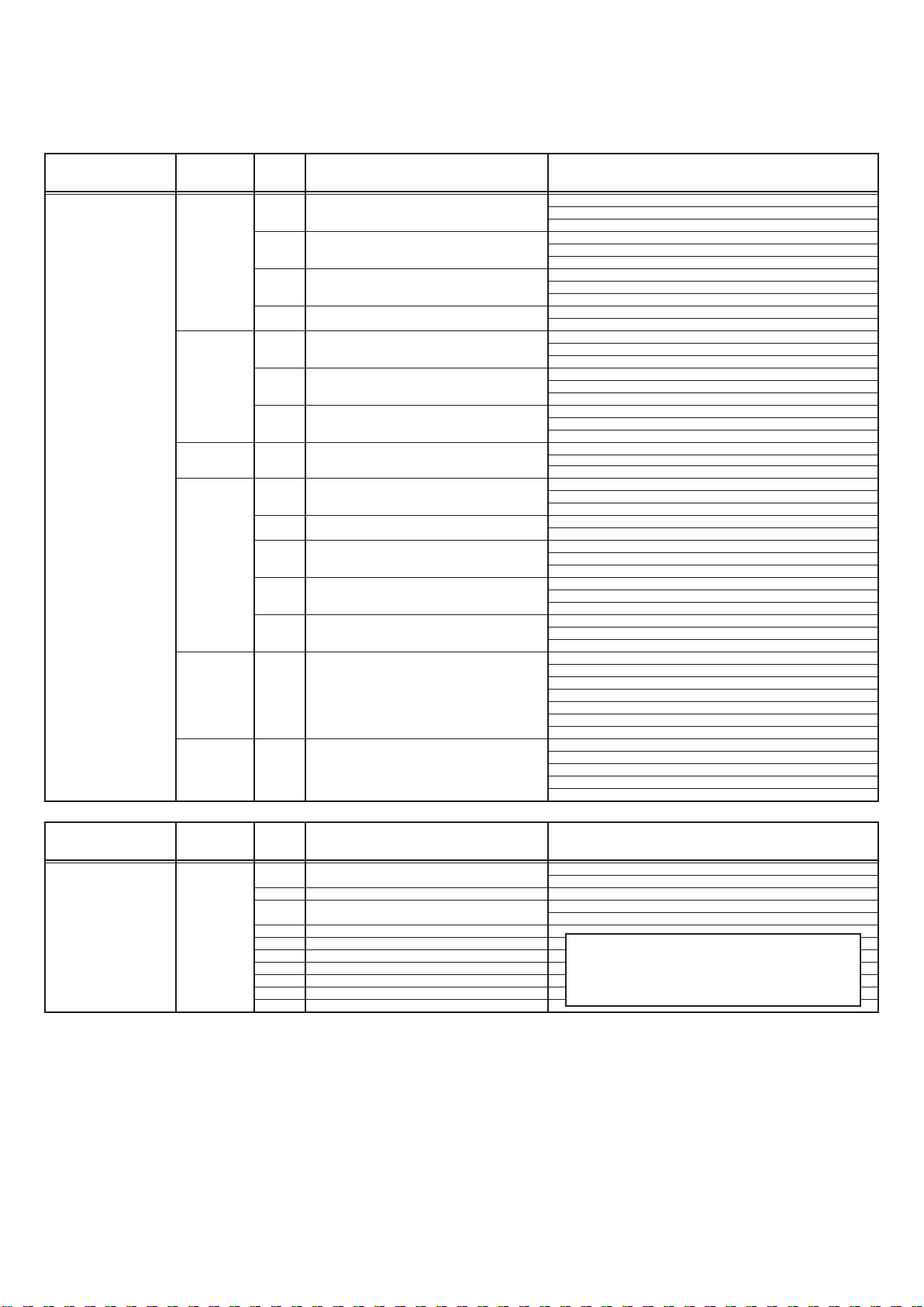
5. APPENDING DATA
5-1 REFRIGERANT CIRCUIT..........................................................................................
5-2 WIRING DIAGRAM....................................................................................................
5-2-1 Indoor Unit............................................................................................................
5-2-2 Outdoor Unit.........................................................................................................
5-2-3 RB Unit.................................................................................................................
5-2-4 Outdoor Air Unit....................................................................................................
5-2-5 Vertical Air Handler...............................................................................................
6. DISASSEMBLY PROCESS
05-01
05-05
05-05
05-14
05-15
05-18
05-20
1. TEST RUN

1. TEST RUN
1-1 EXECUTION PROCEDURE AND EXECUTION PRECAUTIONS
Before execution
Execution zone decision
Confirmation of refrigerant used
Preparation of execution drawings
Confirmation of installation site
Preparations before execution
Execution
Sleeve and insert work
Indoor unit installation
Refrigerant piping work
Drain piping work
Duct work
Heat insulation work
Electrical work
Foundation work for products
Execution procedure and precautions Reason
Check the characteristics of the refrigerant used and grasp the
1
special features of the refrigerant. If refrigerant must be charged,
always charge the refrigerant specified for the product.
Confirm the product design pressure.
2
R410A 609psi (4.20MPa)
Use new refrigerant piping of the thickness specified by the
1
D&T manual.
Since R410A dedicated tools are necessary, prepare them
2
in advance.
Absolutely avoid use of existing piping. If use of existing
3
piping is unavoidable, the piping must be cleaned.
Always use a level and keep the indoor unit level.
If the equipment is tilted toward the drain port, install it so that the tilt is
within 10mm. Excessive tilt will cause water leakage.
When performing piping work, observe the following items so that the
inside of the piping is clean and air tight.
Use pipe that is not dirty inside.
1
When the pipe is left standing, protect it.
2
Finish flaring exactly.
3
Confirm the width across flats dimension and shape of flare nuts.
4
Always blow nitrogen while brazing.
5
Perform flushing before connecting the equipment.
6
Always make the downward slope of the drain pipe 1/100 or
1
greater and make the horizontal length within 66ft.(20m).
Use hard polyvinylchloride pipe as the drain pipe.
2
Support the drain pipe between
3
Use pipe of 1 rank up (VP30 or greater) as central piping.
4
Select the size of the heat insulating material according to the ambient
temperature and relative humidity of the refrigerant.
Use a heat insulating material having a heat conductivity of 0.043W/
.
(m
k) or less.
59-1/16 in(1.5m) to 6-3/4 in ( 2.0m).
Use of a refrigerant other than the
specified refrigerant will invite
equipment trouble.
Secure the necessary pressure
resistance.
Prevention of water leakage
Foreign matter, water, etc. in the
piping will cause faulty cooling and
compressor trouble.
Refrigerant leakage will cause low
performance and abnormal stopping.
Prevention of water leakage
Prevention of water leakage
Products installation work
*Refer to warning or caution in the attached
installation manual of each products
Refrigerant piping connection work
Air tightness test
Vacuum drying
When making flare connections always use a torque wrench and
tighten the flare nut positively to the specified torque.
Pressurize the product with nitrogen gas up to the design pressure
and conduct a 24Hr air tightness test.
1
2
3
*
Refrigerant leakage will cause low
performance and abnormal stopping.
Refrigerant leakage will cause low
performance and abnormal stopping.
Install a vacuum pump with reverse flow check mechanism or a
reverse flow check adaptor to a conventional vacuum pump and
use.
Pump down sufficiently.
Approximately 1 hour or longer after
Allow to stand for approximately 1 hour after stopping the vacuum
pump and confirm that the needle does not return.
Air purging using refrigerant is strictly prohibited.
500 micron (-100.7kPa) reached.
Mixing in of vacuum pump oil by
reverse flow will cause equipment
trouble.
Prevents degradation of the oil by
completely removing water and air.
recommend the vacuuming
*
mode
Vacuuming mode
This function is used for vacuuming the indoor unit and the connection piping.
Note: For starting Vacuuming mode, the refrigerant address setting has to be finished.
When the [vacuuming mode] is set, <Push switch setting, F3:21>
EEV of connected all indoor units opens.
So, the vacuuming indoor unit and piping becomes easier.
When the vacuuming ends, please turn off the power supply for all of the indoor units, RB units
and outdoor unit, [vacuuming mode] is released.
01-01
Execution
Addition refrigerant charging
Gas leak test
Pre-commisioning
"Before Power ON"
Pre-commisioning
"After Power ON"
Confirm the additional refrigerant amount with the installation
1
manual, etc.
Always take the R410A refrigerant from the cylinder liquid phase
2
and charge it using the gas phase.
(Do not lay a cylinder with siphon pipe on its side.)
3
Use an R410A dedicated gauge manifold and charging hose.
Use an R410A dedicated leak tester to check for gas leaks.
Power source installation inspection
1
Field setting and setting inspection
2
Transmission wire installation inspection
3
Piping installation inspection
4
Connect Service Tool
1
Power source inspection
2
Error indication inspection
3
Transmission wire connection inspection
4
Other Field setting with power ON state, and adjustment
If taken from the air phase, since the
composition of the refrigerant which is
charged will change, low performance
and abnormal stop will occur easily.
Prevent erroneous sealing in of
refrigerant.
A leak tester for other than R410A
cannot detect leaks.
Before starting the installed system,
the final inspection is necessary.
When you find out any incorrect install ation or wrong setting, revise it before
starting the system
When you see any abnormal things,
turn OFF the power supply first, and
revise it with power OFF state.
In case of "Auto Address setting"
Note :
Test run & adjustment
Handover & explanation of operation
Check operating condition by using service tool.
For the judgment of operating condition, refer to the operation check
sheet.
Perform the auto address setting of Signal amp. at first, and the next perform the auto address setting of indoor unit.
When you perform the autoaddress setting for RB unit, the indoor unit address setting
needs to be done at first.
When you see any abnormal things,
stop the system, and revise it with
power OFF state.
01-02
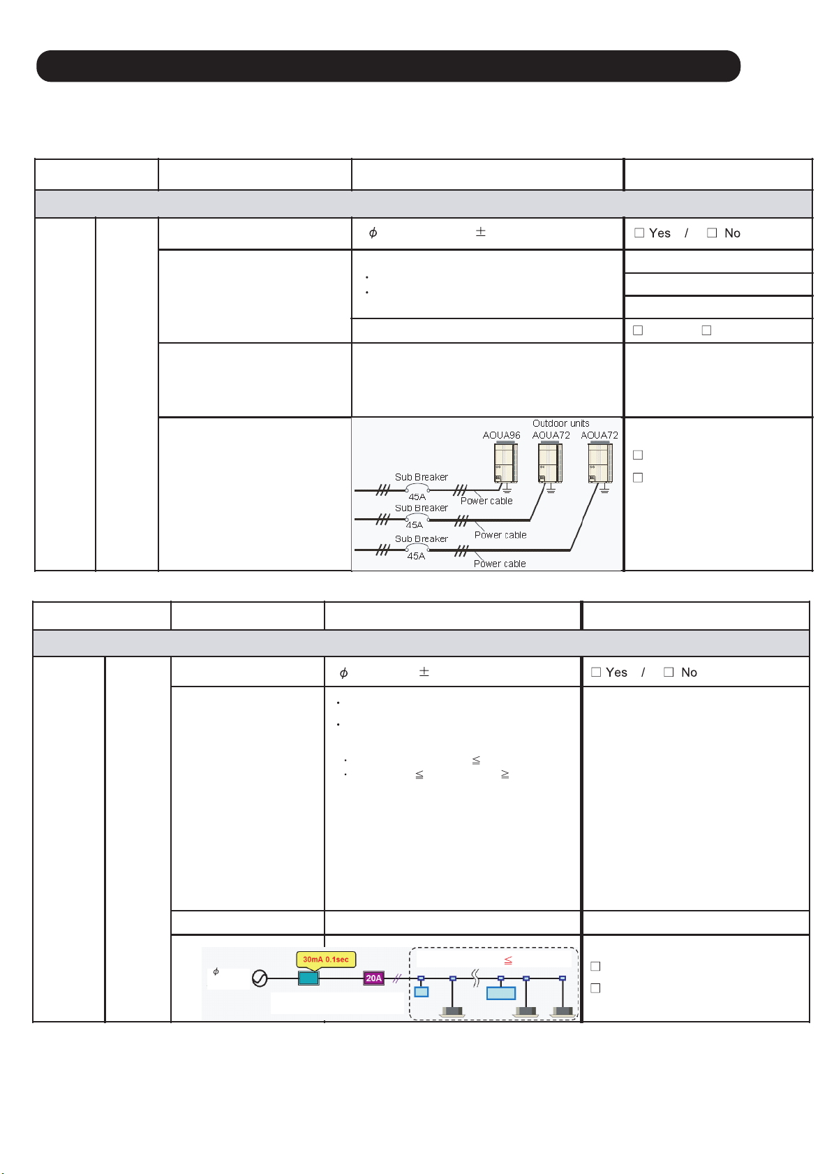
1-2 Check Items Before Power ON
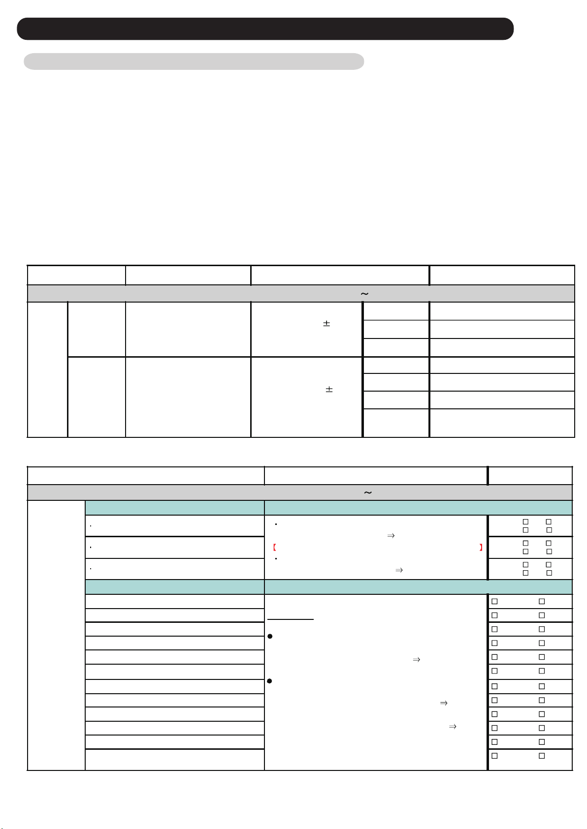
1-2-1 Power source Inspection sheet
Check Item Check contents Judgement Present Status
Ref. circuit name: _________________
Power supply 3 / 3W / (208-230V 10%) / 60Hz
Master (AJUA ___G) :_____(A)
For AJUA72G : 45A
For AJUA90G / 120G : 55A
Leakage current : 100mA, 0.1 sec or less
Check the breaker capacity vs. wire size
Example :
Slave-1(AJUA ___G) :_____(A)
Slave-2(AJUA ___G) :_____(A)
Yes / No
Master : ______ (AWG)
Slave-1: ______ (AWG)
Slave- 2: ______ (AWG)
Complied
Not complied
Power
Source
Outdoor
Unit
Circuit Breaker Size (A)
2
Power Line Wire Size (mm
)
Power line Wiring
Note: One Outdoor Unit must have
one individual Circuit Breaker
* Note: Regulation of wire size and circuit breaker differs from each locality, please refers in accordance with local rule
Check Item Check contents Judgement Present Status
Ref. circuit name: _________________
Power
Source
Indoor
Unit &
RB Unit
Power supply
Circuit Breaker Size (A)
(Check, Leakage current vs.
number of IUs & RB units)
1
/ (208-230V 10%) / 60Hz
20A breaker for one circuit
Leakage current as follows:
No. of units vs. leakage current:
30mA for number of unit 44 units
100mA f or 45 numberr of units 128 units
(Units means Indoor unit + RB unit)
Note:
MCA for total connected units (IU + RB) less
Circuit num ber -1
Breaker capacity: _______ (A)
Nos. of Connected units: ______ (IU+RB)
Circuit num ber -2
Breaker capacity: ______ (A)
Nos. of connected units: _______ (IU+RB)
Circuit num ber -3
Breaker capacity: _______ (A)
Nos. of Connected units
than 15A for 20A breaker capacity
MCA means, minimum circuit ampere
Power line wire size
Power line wiring
1 2W
60Hz 230V
Circut breaker Circuit breaker
Earth lekage Over current
Check the breaker capacity vs. wire size
Example for one circuit
For (IU + RB units) 19 units
Complied
Not complied
: _______ (IU+RB)
________ (AWG)
* Note: Regulation of wire size and circuit breaker differs from each locality, please refers in accordance with local rule
01-03
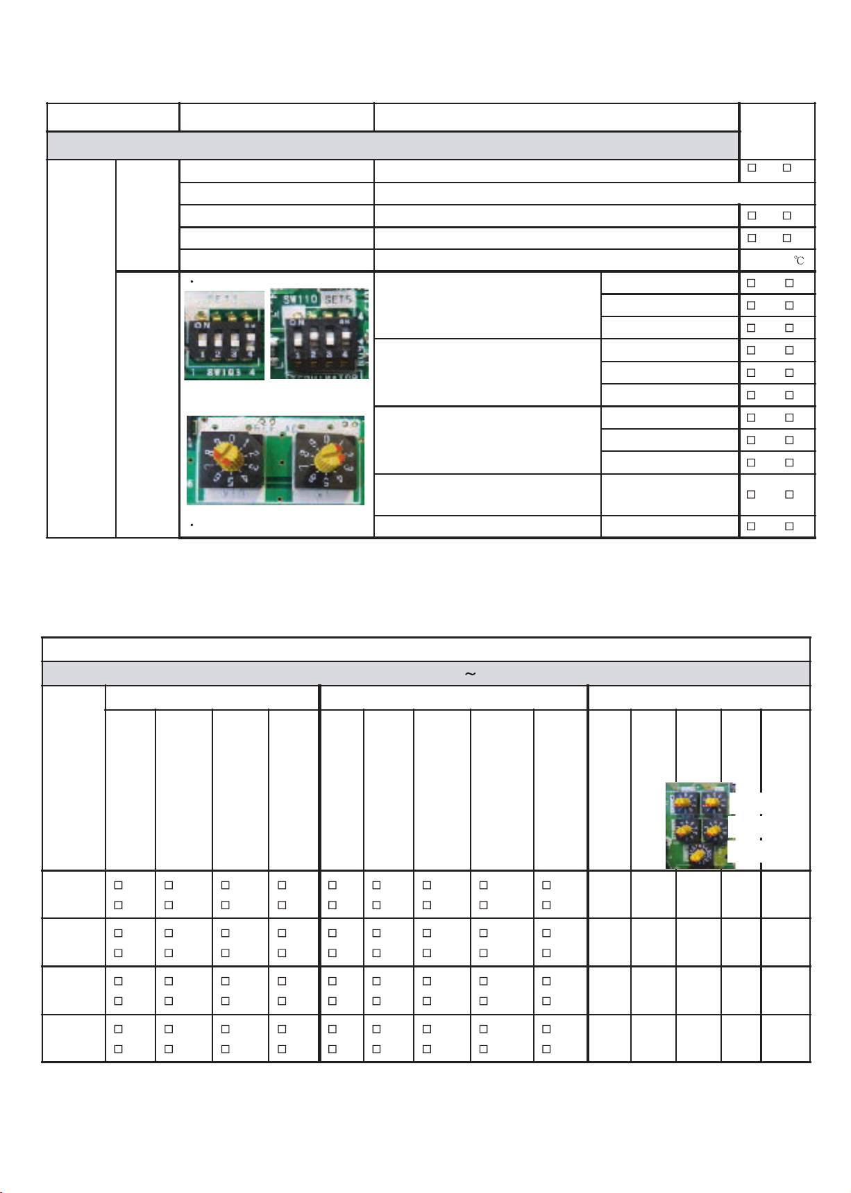
1-2-2 Outdoor unit field setting inspection sheet
Check Item Check contents Judgement
No. of outdoor unit for one ref. circuit: ______, Ref. circuit name: _________________
Appearance Shall be no deformation
Serial No. Master: Slave -1: Slave -2 :
Outlook
Power source & transmission wiring Connection points & loosescrews check
Connection piping Is it insulated properly without gap?
Outdoor air temperature Checked& entered the value
DIP-SW setting
OU Address (SET 3-1 & SET 3 - 2)
Note: setting forMaster & Slave units
(Default : OFF - OFF)
Outdoor
Unit
No. of Slave Unit (SET 3- 3 & SET 3 - 4)
Note: setting for Master unit only
SET-3
SET-5
(Default : OFF- OFF)
Setting
REF-AD
No. of OU (SET 5 - 1 & SET 5 -2)
Note: setting for Master & Slave units
(Default : OFF- OFF)
x10 x1
Rot ary-SW setting
Terminal Register(SET 5 -4)
Note : setting for Master units
Ref. Add. (among Master & Slave units) Ref ADx10 & Ref ADx1
Master (OFF - OFF)
Slave-1 (OFF - ON)
Slave-2 (ON - OFF)
NO Slave (OFF- OFF)
1 x Slave (OFF- ON)
2 x Slave (ON - OFF)
1 x OU (OFF - OFF)
2xOU(OFF- ON)
3 x OU (ON - OFF)
OFF or ON
(Default : OFF)
Present
Status
OK / NG
OK / NG
OK / NG
( )
Y/ N
Y/ N
Y/ N
Y/ N
Y/ N
Y/ N
Y/ N
Y/ N
Y/ N
Y/ N
Y/ N
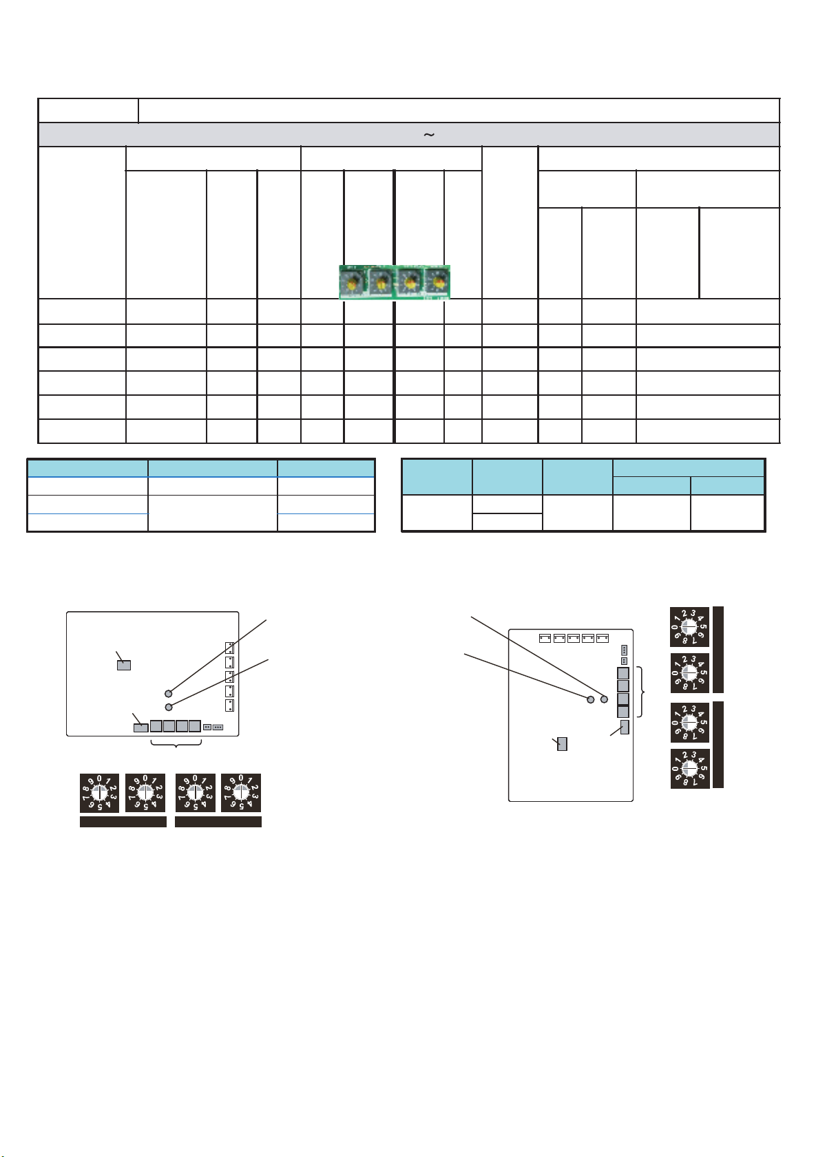
1-2-3 Indoor unit field setting inspection sheet
Check contents
Ref. circuit name: _________________, Ref. address: ____ (00
Model
Name &
Serial
No.
type units)
Y/
N
Y/
N
Y/
N
RC wiring connection points:
(loose / deform)
Y/
N
Y/
N
Y/
N
Access hole for maintenance
Outlook Function setting by DIP-SW (Off / On) Add. Setting (by Rotary-SW)
(For Duct type & Cassette
Refrigerant pipes insulation
Y/
N
Y/
N
Y/
N
Drain pipes installation
(default:
2
wire)
Y/
N
Y/
N
Y/
N
Wired RC setting (DIP SW
2
wire /
3
wire
1
)
Y/
N
Y/
N
Y/
N
External Input (edge/pulse)
SET
2
2
( default: OFF )
Y/
N
Y/
N
Y/
N
SET
( default: OFF )
3
1
Y/
N
Y/
N
Y/
N
99)
Wireless RC custom code
SW
SET
( default: OFF )
Wireless RC custom code
SW
1
Y/
N
Y/
N
Y/
N
2
3
2
Drain Pump SW (for Slim duct)
SET
( default: OFF )
4
1
Y/
N
Y/
N
Y/
N
(REF AD x
10
)
(REF AD x
Ref. Add.
1
)
Ref. Add.
(IU AD x
10
)
(IU AD x
IU Add.
1
)
IU Add.
IU Add.
Ref . Add.
RC Add
RC Add.
(RC AD)
Y/
N
Y/
N
Y/
N
Y/
N
Y/
N
Y/
N
01-04
Y/
N
Y/
N
Y/
N
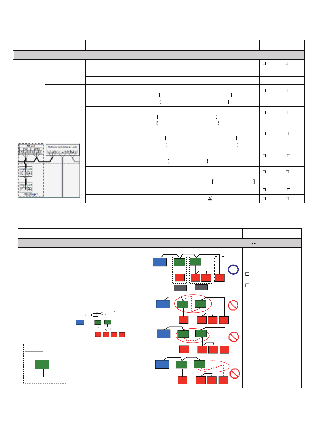
1-2-4 RB unit field setting Inspection sheet
RB Unit Check contents
Ref. circuit name: _________________, Ref. address :__(00
Outlook
Transmission & Power
line wiring connection
terminal
(Loose / Tilting )
Access hole for
maintenance
( Have / Not have )
Model Name
RB unit (single type) Indoor units / Branch Total capacity
UTP- RU01AH Maximum 3 uni ts 8.0 kW or less
UTP- RU01BH
UTP- RU01CH 28.0 kW or less
Maximum 8 units
RB unit Add. set by Rotary-SW
Refrigerant piping
insulation
Ref. Add.
(REF AD x
10
)
Ref. Add.
18.0 kW or less
Ref. Add.
(REF AD x
1
)
99)
(IU AD x
RB Add.
(IU AD x
10
)
RB Add.
(multi type)
UTP-RU04BH
RB unit
1
)
RB Add.
Related
Indoor
Unit
Address
Number of
RB units
1 unit
2 units series
No. of connected IU vs. total capacity
For single type
RB unit
Number of
Connected IUs
connected IUs
Indoor unit
/ Branch
Maximum
8 units
For multi type RB unit
(single / series connection)
Total capacity
(kW) of the
Each Branch Total
Up to 18.0kW Up to 56.0kW
Number of
Connected IUs
Capacity
the connected IUs
Total capacity
(kW) of
Single type RB unit
PC board (Upper side)
DIP switch
SET1
DIP switch
SET2
REF × 1
× 10
SV connector
Rotary switch
× 10
RB × 1
Power indicator
lamp (Green)
Error indicator
lamp (Red)
Error indicator
lamp (Red)
Power indicator
lamp (Green)
Multi type RB unit
PC board (Upper side)
SV connector
DIP switch
SET1
DIP switch
SET2
RB × 1
× 10
REF × 1
× 10
01-05
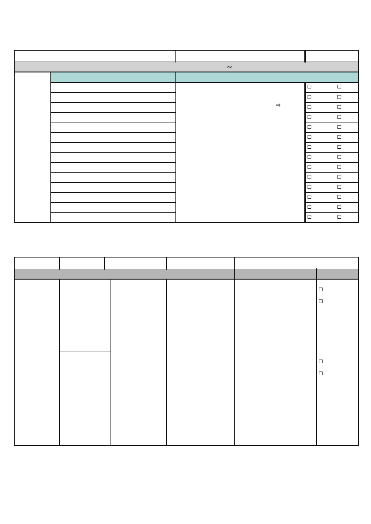
1-2-5 Transmission wire installation inspection sheet 1/3
Check Item Check contents Judgement Present Status
Number of ref. circuit connected in the network system: ______, Ref. addresses: ______________(00 - 99)
VRF
Network
System
Transmission wire
Transmission line
connection points
Outlook
Wire specification 0.33mm
For cooling only IU
Between RB unit & IU
For Heat Recovery IU
Between RB unit & IU
Is it LonWorks compatible?
Maker name?
2
, shield wire
Must be properly connected (Between RB unit & IU)
RB unit
Tterminal (OUT/U) : X1, X2, Earth
IU Terminal (IN/U) : X1, X2, Earth
Must be properly connected (Between RB unit & IU)
RB unit Tterm ina l (I N/U) : X1, X2 , Earth
IU Termina l (IN/U) : X1, X2, Ea rth
Yes / No
(AWG)
Yes / No
Yes / No
Between
RB unit & Master OU
Between Master OUs
Between Master OU &
Slave OU or
Must be properly connected
RB unit Terminal (OUT/U) : X1, X2, Earth
Master OU
Terminal (RB/U) : X1, X2, Earth
Must be properly connected (Between Master OUs)
Master OUs
Terminal: Z1 & Z2
Must be properly c onne cted (Between Master OU and
Slave OU / Slave OU and Slave OU )
In between Salve OUs
Shield wire connection
Both ends of shield wire must be grounded
Wiring connection Wiring connection per terminal (
(Between RB unit & Master OU)
Terminal: H1 & H2
2)
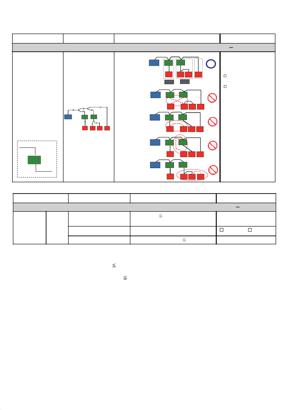
Check Item Check contents Judgement Present Status
Number of ref. circuit connected in the network system: ______, Ref. addresses: ______________(00
Correct Layout
Transmission line layout
OU
RB
RB
(Between RB unit & IU)
Reference:
(Piping Layout)
Not Correct Layout
Example
-1
OU
IU
RB Gr.
RB
IU
RB Gr.
RB
IU
IU
99)
Correct
Not correct
If not correct, pls.
rectify the connection
Yes / No
Yes / No
Yes / No
Yes / No
Yes / No
Transmission line
Reference:
From outdoor
unit
RB
To indoor
unit
OU
RB
RB
Not Correct Layout
IU
IU
IU
IU
Example - 2
IU
IU
IU
IU
Not Correct Layout
Example
-3
OU
OU
RB
IU
RB
IU
RB
RB
IU
IU
IU
IU
IU
IU
01-06
1-2-5 Transmission wire installation inspection sheet 2/3
Check Item Check contents Judgement Present Status
Number of ref. circuit connected in the network system: ______, Ref. addresses: ______________(00
Transmission line
Reference:
From outdoor
unit
RB
To indoor
unit
Transmission line layout
(Between RB unit & IU)
Reference:
(Piping Layout)
OU
RB
RB
IU
IU
IU
IU
Correct Layout
Not Correct Layout
Example - 1
Not Correct Layout
Example - 2
Not Correct Layout
Example - 3
Not Correct Layout
Example - 4
OU
OU
OU
OU
OU
RB
IU
RB Gr.
RB
IU
RB
IU
RB
IU
RB
IU
RB
IU
RB Gr.
RB
RB
RB
RB
IU
IU
If not correct, pls.
IU
IU
IU
IU
IU
IU
IU
IU
IU
IU
IU
IU
rectify the connection
99)
Correct
Not correct
Check Item Check contents Judgement Present Status
Number of ref. circuit connected in the network system: ______, Ref. addresses:_______________(00 99)
VRF Network
System
Network
wiring
Total transmission line length
Network wiring layout
No. of network segment
( * 1 )
Create one Network Segment based on the following conditions,
Wiring length
(Value taken from Network Design Drawing)
Do not make a loop configuration Looped / Notlooped
( * 1 )
No. of network segment 41
11811ft.(3600m)
Condition -1: if the transmission line length 1640ft.(500m)
Condition -2: if a total number of connected units
( * 2)
connected units mean a total of (Indoor Units + Master Outdoor Units + RB Units
Netwo rk Convertor f or LonWo rks Unit + Central RC Units + Netwo rk Co nv erto r Units +
BACnet Gateway Unit + Signal Amplifier Units + Service Tool Unit + Web Monitoring Tool Unit)
*
( 3)
f or s ing le ty pe RB Unit, c ount as ‘0’, f or multiple type RB Unit, when all port s are co nnected with Indo or Unit, count as ‘0’.
However, if one of the port of the multiple type RB Unit is not connected with Indoor Unit, at that time count as one RB Unit.
64 connected units
( * 2 )
( * 3)
+ TPC Uni ts + S ys tem Controller Units
(m)
01-07
1-2-5 Transmission wire installation inspection sheet 3/3
Check Item Check contents Judgement Present Status
Number of ref. circuit connected in the network system : ______, Ref. addresses :_______ _______________(00
VRF
Network
System
Network
Configuration
No. of IUs & OUs
No. of System Controller
No. of Touch panel controller (TPC)
No. of Central RC (CRC)
No. of Network Convert for Group RC
No. of Signal Amplifier (SA) 40
Detail contents:
No. of SA (filter mode OFF) 8
No . of SA (f ilter m ode ON ) 32
No. of Network Convertor ( 100)
No. of BACnet Gateway
Terminal Register
No. of Network Convertor for LonWorks
For one VRF Network System
(IU
400 & OU 100)
One System Controller per VRF Network System
Connectable Nos. 16
Connectable Nos. 16
Connectable Nos. 64
One per 1640ft.(500m) t ra nsmission line length OR,
One per 1312ft.(400m) transmission line length
between units OR,
One per every 64 number of connected units OR,
One per every master OU if total number of
connected Indoor Units
One for each separate Room Air- conditioning system Total:_______
One BACnet Gateway per VRF Network System Total: _______
One per Network Segment (refer to table -9) Total: _______
One per VRF Network System (IU 128 & OU 100)
NOTE: Special VRF Network system configuration
Total 16 Nos.
Per VRF Network System
(including one Network
Converter for LonWorks)
320
IU number : _____
OU number: _____
TPC: _____
CRC: ______
Group RC: _____
Num be r of Signa l
Amplifier :________
IU number : _____
OU number: _____
99)
Check Item Check contents Judgement Present Status
Number of ref. circuit connected in the network system : ______, Ref. addresses :_______________________(00
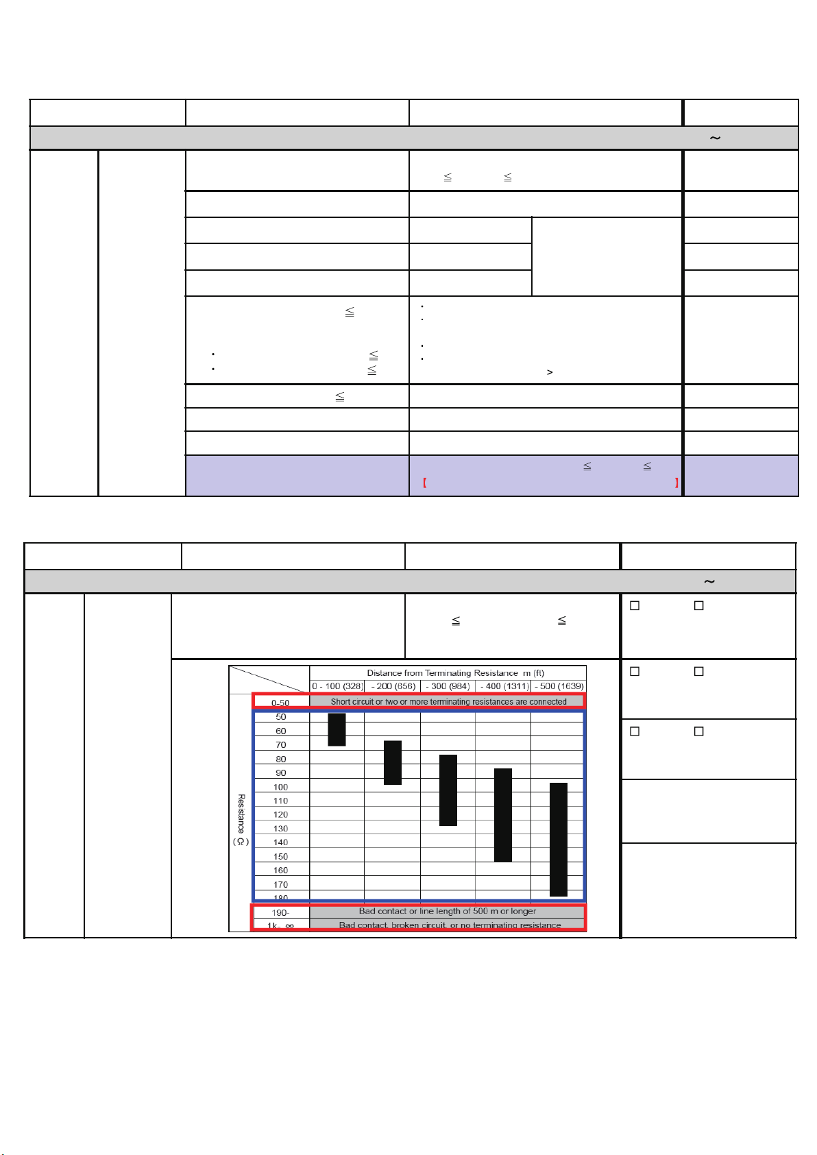
Terminal resistance of transmission line:
From device with connected terminal
resistance (OU or SA) to the most
distance device
50 ohm ( Resistance value) 180 ohm
OK / Not OK
In- between
OU (add__ __) & SA (ad d___)
OK / Not OK
In- between
SA (add____) & RB (add___)
OK / Not OK
VRF
Network
System
Terminal
Resistance of
transmission
line
In- between
OU (add__ __) & SA (ad d___)
99)
01-08
1-2-6 Piping installation inspection sheet 1/2
Check Item Check contents Judgement Present Status
Ref. circuit name : _________________________________, Ref. address: ______________ (00
Insulation & Fastening Insulated without gap & properly fastened (Yes / No)
Outlook
Suction line filter Is there any external filter in the suction line
Oil Trap If Distance between OUs 2m ,
Place oil trap both at suction & at Discharge line
541ft./165m) (feet)
197ft./60m) (feet)
3280ft./1000m) (feet)
Refrigerant
system
piping
Actual Pipe Length
Between Master OU and farthest IU (
Between first separation tube and farthest IU (
Total Pipe Length (
Between OU and OU branch kit (
Between farthest OU and first OU branch kit (
Between RB units (for multi type RB series connection) ( 3ft./1m) (feet)
Piping
Between OU and IU (when OU is installed above) ( 164ft./50m) (feet)
Between OU and IU (when OU is installed below) ( 131ft./40m) (feet)
Between IUs (
49ft./15m) (feet)
Height Difference
Between OUs (
Between RB units (
1.6ft./0.5m) (feet)
49ft./15m) (feet)
Between RB unit and IU (
99)
Yes / No
Yes / No
Yes / No
Not applicable
9ft./3m) (feet)
39ft./12m) (feet)
16ft./5m) (feet)
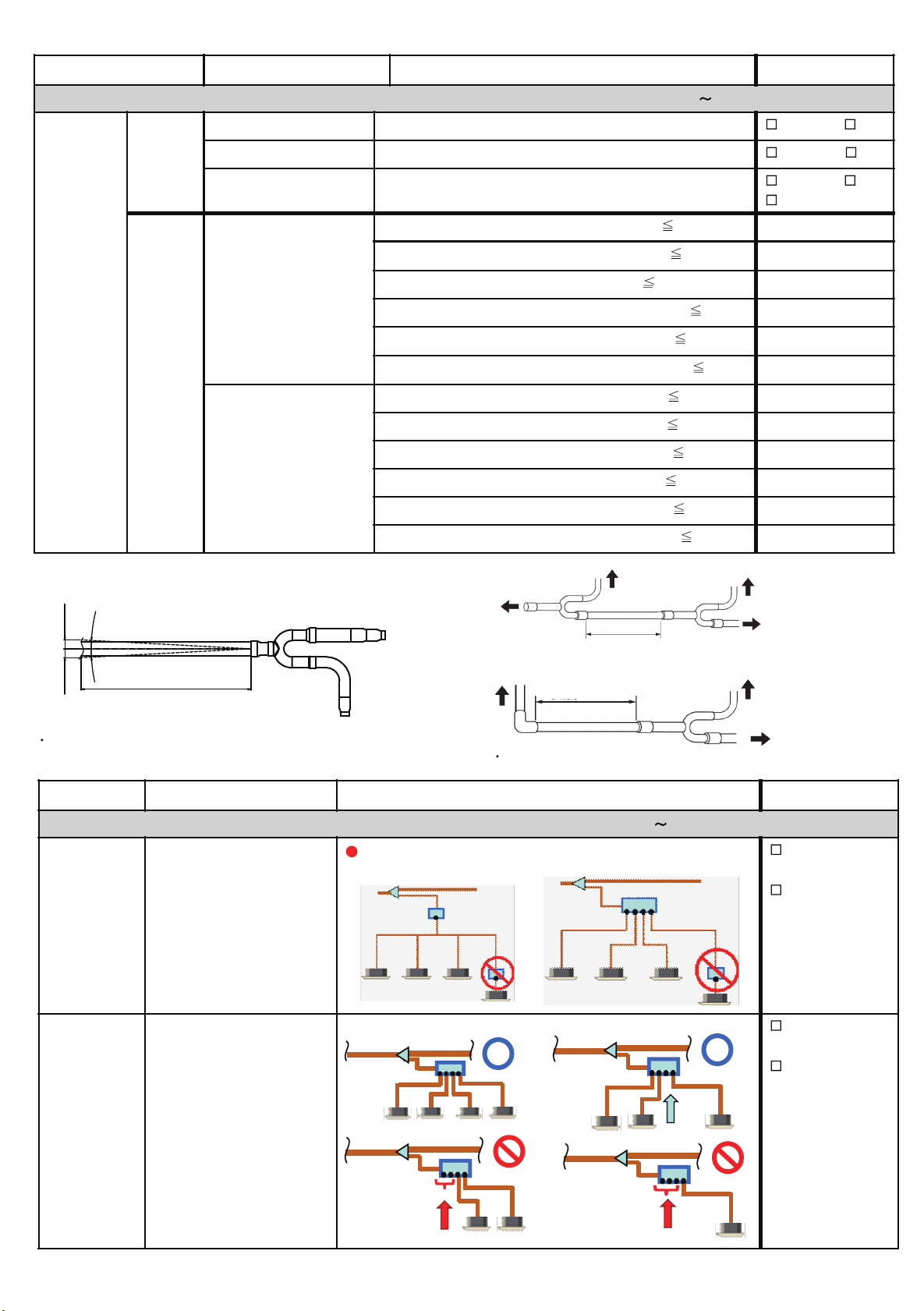
Other check point of separation tube
Bending of connection pipe toward separation tube.
( 3° )
0 to 26 mm
( 3° )
0 to 26 mm
Like the figure, adjust the pipe angle so as to be within 3-degree angle.
Connection pipe
19-11/16in. (0.5m)
Separation tube
to Outdoor unit
to Outdoor unit
to RB unit or
Indoor unit (To
main pipe
to RB unit or
Indoor unit (To
main pipe
19-11/16in.(0.5m) or more
Leave the distance 19-11/16in.(0.5m) or more for straight part to outdoor unit branch kit.
to Outdoor unit
19-11/16in.(0.5m) or
more
to Outdoor unit
to Outdoor unit
to Outdoor unit
to Outdoor unit
Check Item Check contents Judgement Present Status
Ref. circuit name: ____________________________________, Ref. address: _____(00
Existence of additional RB in between RB branch port and indoor
unit is prohibited
For single
type & multi
type RB Units
Piping layout
(Between RB & IU)
For single type
RB unit
99)
For multi type
RB unit
Correct
Not correct
For multi type
RB Unit
Branch port piping layout
(RB branch port vs. IU
connection pattern)
1) Number of free branch port more than one is p rohibited Correct
Not correct
1 free blanch
2 free branch
3 free branch
01-09
1-2-6 Piping installation inspection sheet 2/2
Check Item Check contents Judgement Present Status
Ref. circuit name: _______________________________________, Ref. address:
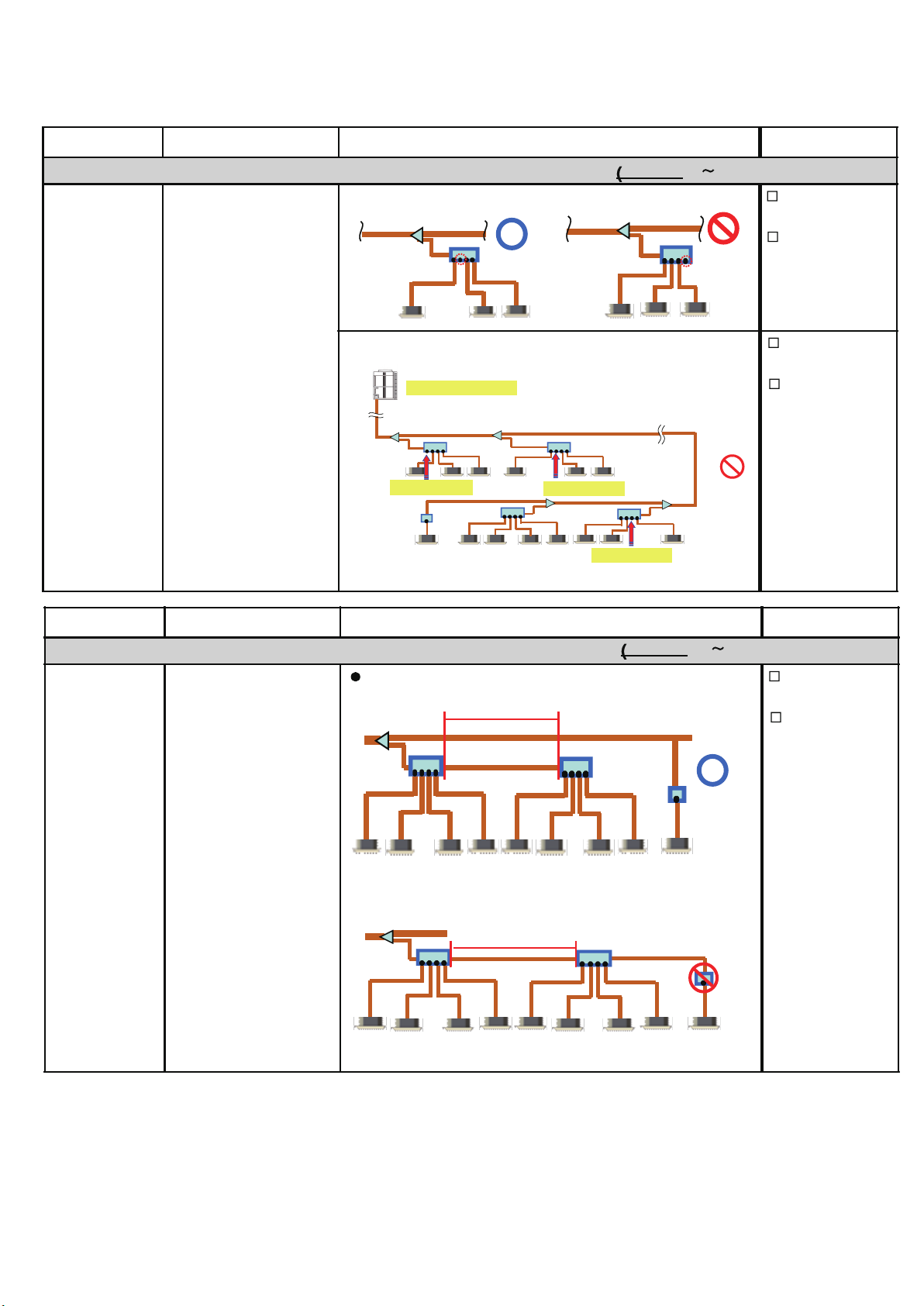
2)
Connect the IU to the RB unit in order of farthest branch port Correct
Keep free branch port within 2 or less per refrigerant cycle Correct
For multi type RB
Unit
Branch port piping layout
(RB branch port vs. IU
connection pattern)
One refrigerat ion cy cle
1stnot used port
2ndnot used port
3rdnot used port
(
(00 99)
Not correct
Not correct
Check Item Check contents Judgement Present Status
Ref. circuit name: _______________________________________, Ref. address:
Maximum two RB units (for multi type) in series is allowable Correct
within 1m
(
(00 99)
Not correct
For multi type RB
Unit
RB series connection
within 1m
01-10
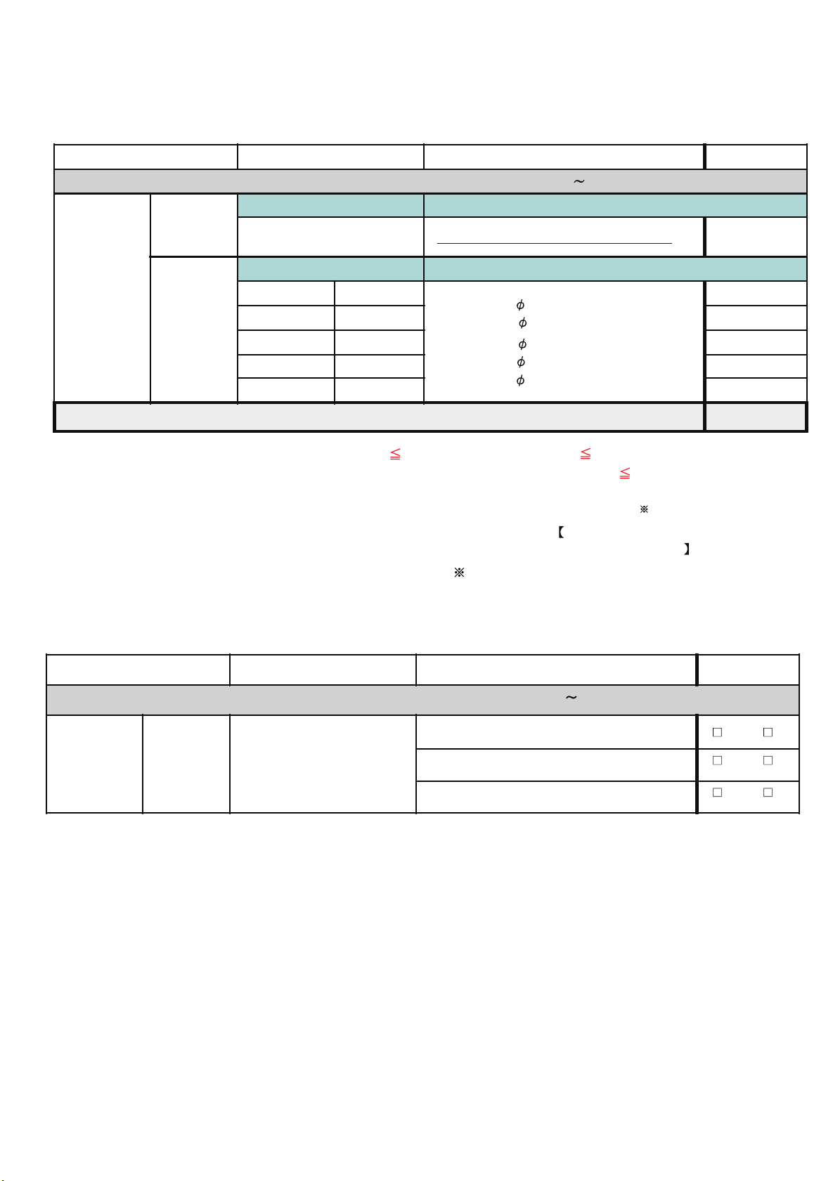
1-2-7 Refrigerant charge amount inspection sheet
Check Item Check contents Judgement Present Status
Ref. circuit name: ____________________________, Ref. address :________(00
OU Model Name Additional Refrigerant Amount for OU
99)
Outdoor Unit
AJUA72G / AJUA90G / AJUA120G AJ*A72G / AJ*A90G / AJ*108G : 6.31lbs / 3.0kg
Liquid Pipe Length Additional Refrigerant Amount based on the li quid pipe leng th
Additional
Charged
Refrigerant
Connecting
Pipe
@ 6.35mm (ft)
@ 9.52mm (ft)
@ 12.7mm (ft)
@ 15.88mm (ft)
@ 19.05mm (ft)
For pipe diameter 6.35mm : 0.014 lbs./ft.(0.021 kg/m)
For pipe diameter 9.52m m : 0.039 lbs./ft.(0.058 kg/m)
For pipe dia meter 12.7mm : 0.077 lbs./ft.(0.114 kg/m)
For pipe dia meter 15.88mm:0.120 lbs./ft.(0.178 kg/m)
For pipe dia meter 19.05mm :0.180 lbs./ft.(0.268 kg/m)
Total Additional Amount of Charged Refrigerant =
Note: In the refrigerant system, overall refrigerant amount 77.16 lbs / 35 kg / (for 1 OU), 154.3 lb / 70kg (for 2 OUs) and
231.5 lbs / 105 kg (for 3 OUs)
Overall refrigerant amount (kg) in the refrigerant system = Factory charged refrigerant (lb/kg) for OU
charged refrigerant (lb/kg)
= Add itional charged refrigerant for OU +
+ Total additional amount of
Additional charged refrigerant for connecting pipe
Factory charged refrigerant for outdoor unit :
AJUA72G or AJUA90G or AJUA120G : 26.01lbs.11.8(kg)
(kg)
(lbs)
(lbs)
(lbs)
(lbs)
(lbs)
(lbs)
1-2-8 3-way valve opening inspection sheet
Check Item Check contents Judgement Present Status
Ref. circuit name: ____________________________, Ref. address :________(00
Master OU ( all 3-way valve must be full open )
Slave-1 OU ( all 3-way valve must be full open )
Slave-2 OU ( all 3-way valve must be full open )
Outdoor Unit
3-way
valves
opening
3-way valve of each OU at
- Discharge pipe side
- Suction pipe side
- Liquid pipe side
99)
Yes / No
Yes / No
Yes / No
01-11
1-3 Check Items After Power ON
Overview of system operation check procedure
Step-1: Connect Service Tool PC to the VRF VR-II system.
Do scaning of refrigerant system which should be commissioned.
Step-2: Compare the number of installed units (OU, RB Group and IU) with the System List data obtained from the Service Tool.
Step-3: Operate all Indoor Units under Test Mode Cooling (Select Test mode either cool or heat based on ambient temperature.).
Step-3-1: During operation, check the RB unit SV status and IU thermistor value
Step-3-2: After 1-hour operation, check the Refrigerant System
Step-4: After 1-hour Test run operation (excluding special operation),
Step-4-1: Switching the operation mode of IU, in order of RB group number, from cool to heat.
- Check the RB unit SV status and IU thermistor value
Step-4-2: When all IUs run under heating, continue operation minimum 15min. And check the Refrigerant system
1-3-1 Power source check sheet
Check Item Check contents Judgement Present Status
Ref. circuit name _______________________, Ref. address ________(00
Actual Power Supply (V)
Outdoor Unit
Between L1-L2 / L1-L3 / L2-L3
< 3N, 3Wire + ground, 60Hz >
AC (208 - 230V)
Incoming voltage per breaker
10%
Power
Source
Indoor Unit
&
RB Unit
Actual Power Supply (V)
< 1, 2Wire + ground, 60Hz >
AC (208 - 230V) 10%
Incoming voltage per breaker
1-3-2 Error indication check sheet 1/2
Check Contents Judgement Present Status
Ref. circuit name ________________________, Ref. address ________(00
Outdo or unit Check PCB- Lighting status
LE D1 01 (green li ght)
Judgment : mu st be ON
Note : LED102 (Red) must not be flash & must not be ON
7-SEG LED
Judgment : ‘Sn’ displayed
Indoor Unit
For Wall mounted, Universal, Celling & Small Cassette
Check IU operation LED & timer LED condition
Judgment : must be flashing alternately
For Large Cassette and Duct type IU
Check Wired RC (3- wire) display screen
Judgmen t : C lock dis pla y “ AM 12: 00” will ap pe a r
Check Wired RC (2-wire) display screen
Judgmen t : La n gu a ge selec tion sc ree n will a ppe a r
For each
refrigerant
system
Master
Slav e -1
Slav e -2
Indoor unit Check LED & RC display status
IU address _______ (RB a ddress ________ )
IU address _______ (RB a ddress ________ )
IU address _______ (RB a ddress ________ )
IU address _______ (RB a ddress ________ )
IU address _______ (RB address ________ )
IU address _______ (RB address ________ )
IU address _______ (RB address ________ )
IU address _______ (RB address ________ )
IU address _______ (RB a ddress ________ )
IU address _______ (RB address ________ )
IU address _______ (RB address ________ )
IU address _______ (RB address ________ )
99)
Master (V): R-S:_____ / S-T:____ / T-R:____
Slave -1 (V): R-S:_____ / S-T:____ / T-R:____
Slave -2 (V): R-S:_____ / S-T:____ / T-R:____
Breaker-1 (V): _______
Breaker-2 (V): _______
Breaker-3 (V): _______
_______
99)
LED101: Yes No
Yes / No
Yes / No
Yes / No
Yes / No
Yes / No
7-S EG :
LED101: Yes No
7-S EG :
LED101: Yes No
7-S EG :
Yes No
Yes No
Yes No
Yes No
Yes No
Yes No
Yes No
Yes No
Yes No
Yes No
Yes No
Yes No
Yes No
Yes No
Yes No
01-12
1-3-2 Error indication check sheet 2/2
Check Contents Judgement Present Status
Ref. circuit name ________________________, Ref. address ________(00
RB unit & respectiv e IU address (Desig n Value) Check RB unit PCB-LED status
RB address _______ (IU address _____________)
LED1 (Green )
Judgment :
Note: LED2 (Red) of R B u n it must not be ON
For each
refrigerant
system
RB address _______ (IU address _____________)
RB address _______ (IU address _____________)
RB address _______ (IU address _____________)
RB address _______ (IU address _____________)
RB address _______ (IU address _____________)
RB address _______ (IU address _____________)
RB address _______ (IU address _____________)
RB address _______ (IU address _____________)
RB address _______ (IU address _____________)
RB address _______ (IU address _____________)
RB address _______ (IU address _____________)
RB address _______ (IU address _____________)
RB address _______ (IU address _____________)
1-3-3 Installed unit and their addresses check sheet
99)
mu st be ON
Yes / No
Yes No
Yes No
Yes No
Yes No
Yes No
Yes No
Yes No
Yes No
Yes No
Yes No
Yes No
Yes No
Yes No
Yes No
Check Contents Check items Checking method Judgement Present Status
Ref. circuit : Name _________________, Ref. address ________(select from 00 to 99) Design value Check status
Installed units
and
their addresses
check
Number of IU
IU address
Number of RB unit
RB unit address
Checked by
Service Tool
Number of units and their
address appeared in the
System List must be same
as the Actual Design value
Judgment:
(OK / Not OK)
Connected number of IU ______
Connected number of RB Gr. ___
IU add _____ (RB a dd ____ )
IU add _____ (RB a dd ____ )
IU add _____ (RB a dd ____ )
IU add _____ (RB a dd ____ )
IU add _____ (RB a dd ____ )
IU add _____ (RB a dd ____ )
IU add _____ (RB a dd ____ )
IU add _____ (RB a dd ____ )
IU add _____ (RB a dd ____ )
IU add _____ (RB a dd ____ )
IU add _____ (RB a dd ____ )
IU add
_____ (RB a dd ____ )
IU add _____ (RB a dd ____ )
IU add _____ (RB a dd ____ )
IU add _____ (RB a dd ____ )
OK
Not OK
OK
Not OK
01-13

1-3-4 Transmission line connection check sheet
Note: The following check method by using test-run is necessary for checking of incorrect transmission wire connection.
Check Contents Check items Checking method Judgement Present Status
Ref. circuit : Name _________________, Ref. address ________(select from 00 to 99)
Judgment Point during
test - mode cooling :
Transmission line
connection
co nfirmation
check
Cooling status
Operate all Indoor
Units under Test-run
Cooling Mode by
using Commissioning
Function of Service
Tool
For In door Unit
- Thermist or v a lue
(TH21 - TH22)14.4 F 8
(Yes / No)
For RB Un it
-SV status
SVB1 & SVS mu st ON
(Yes / No)
Desi gn value
IU add _____ (RB add ____)
IU add_____ (RB a dd ____)
IU add_____ (RB a dd ____)
IU add_____ (RB a dd ____)
IU add_____ (RB a dd ____)
IU add_____ (RB a dd ____)
IU add_____ (RB a dd ____)
IU add_____ (RB a dd ____)
IU add_____ (RB a dd ____)
IU add_____ (RB a dd ____)
IU add_____ (RB a dd ____)
IU add_____ (RB a dd ____)
IU add_____ (RB a dd ____)
IU add_____ (RB a dd ____)
IU add_____ (RB a dd ____)
Check sta tus
IU RB
Yes / No Yes / No
Yes / No Yes / No
Yes / No Yes / No
Yes / No Yes / No
Yes / No Yes / No
Yes / No Yes / No
Yes / No Yes / No
Yes / No Yes / No
Yes / No Yes / No
Yes / No Yes / No
Yes / No Yes / No
Yes / No Yes / No
Yes / No Yes / No
Yes / No Yes / No
Yes / No Yes / No
Check Contents Check items Checking method Judgement Present Status
Ref. circuit : Name _________________, Ref. address ________(select from 00 to 99)
Judgment Point after
switching IU mode from
cool to heat in order of
Transmission line
connection
co nfirmation
Heating status
Switching the operation of IU
from cool to hea t in order of RB
group number by using,
Control function of Service Tool
RB group number:
For Indoor Unit
- Thermist or v a lue
(TH24 > TH21)
(Yes / No)
IU add _____ (RB a dd ____)
IU add _____ (RB add ____)
IU add _____ (RB add ____)
IU add _____ (RB add ____)
IU add _____ (RB add ____)
IU add _____ (RB add ____)
IU add _____ (RB add ____)
IU add _____ (RB add ____)
IU add _____ (RB add ____)
IU add _____ (RB add ____)
IU add _____ (RB add ____)
IU add _____ (RB add ____)
IU add _____ (RB add ____)
IU add _____ (RB add ____)
IU add _____ (RB add ____)
Desi gn value
Check status
IU
Ye s / No
Ye s / No
Ye s / No
Ye s / No
Ye s / No
Ye s / No
Ye s / No
Ye s / No
Ye s / No
Ye s / No
Ye s / No
Ye s / No
Ye s / No
Ye s / No
Ye s / No
01-14
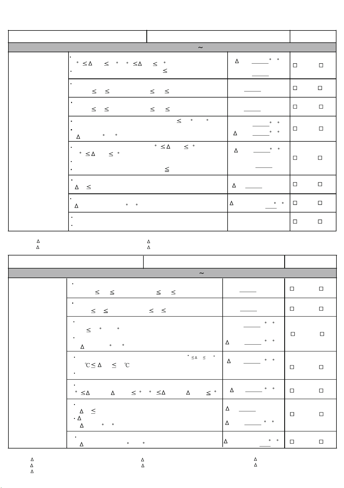
1-3-5 Operation check sheet
Check Contents Judgement Present Status
Refrigerant Circuit : Name _________________, Address ________(00
Degree of sub-cool at OU sub - cooler side should be,
9 F TSC 36 F(5 C Tsc 20 C) AND
Pulse value EEV3 should be,
EEV3 400P
Discharge refrigerant pressure should be,
Test-run operation
Cooling mode
363psi Pd 479psi(
2.5MPa Pd 3.3MPa)
Suction refrigerant pressure should be,
102psi Ps 174psi(
0.7MPa Ps 1.2MPa)
Discharge refrigerant temp. should be,
Td 212 F(100 C).And,
Discharge refrigerant superheat should be,
( Tshd >18 F(10 C)
Conducted by
Service Tool
IU refg. superheat should be,
(2 C Tshe 5 C).And,
(3.6 F Tshe 9 F)
RB group SV (SBS & SVB1) should be ON AND
Pulse value IU EEV should be, EEV 1000P
Ps between Master & Slave OUs should be,
( Ps 29psi(0.2Mpa))
Air temperature of each RB group IU should be,
Tair c ooling
14.4 F(8 C)
>
99)
Tsc
F( C)
EEV3 P
Pd Psi(MPa)
Ps Psi(MPa)
Td
Tshd
Tshe
SBS & SVB1 ON
F( C)
F( C)
F( C)
IU EEV P
Ps Psi(MPa)
Tair c ooling
F( C)
Yes / No
Yes / No
Yes / No
Yes / No
Yes / No
Yes / No
Yes / No
No water fall from IU
No abnormal noise from IU
Reference mark of Service tool
Tsc = Saturated liquid temperature of HPS - TH5
Tshd = TH1- Saturated liquid temperature of HPS
Tshe = TH24 - TH22
Tair c ooling = TH21 - Outlet Air temperature
Check Contents Judgement Present Status
Refrigerant Circuit : Name _________________, Address ________(00
Discharge refrigerant pressure should be,
363psi Pd 479psi (2.5MPa Pd 3.3MPa)
Suction refrigerant pressure should be,
Test-run operation
Heating mode
44psi Ps 174psi (0.3MPa Ps 1.2MPa)
Discharge refrigerant temperature should be,
Td 212 F (100 C) AND
Discharge refrigerant superheat should be,
Tshd > 18 F(10 C)
7.2 F 12.6 F
Conducted by
Service Tool
Degree of sub
(4
cool (at IU side) should be,
Tsc 7 ) AND
RB group SV (SBD1 & SVB2) should be ON
Refrigerant superheat (at OU side) should be,
3.6 F Tshe1& Tshe2 9 F(2 C Tshe1& Tshe2 5 C)
Td = TH1
99)
Tsc
Ye s / No
Pd = HPS
Ps = LPS
Pd Psi(MPa)
Ps Psi(MPa)
Td
Tshd
Tsc
SVD1 & SVB2 ON
Tshe
F( C)
F( C)
F( C)
F( C)
Yes / No
Yes / No
Yes / No
Yes / No
Yes / No
Reference mark of Service tool
Tsc = Saturated liquid temperature of HPS - TH22
Tshd = TH1- Saturated liquid temperature of HPS
Tair heating = TH21 - Outlet Air temperature
Pd between Master & Slave OUs should be,
Ps 29psi (0.2MPa))
T
at each OU connected in series should be,
OUHE
TOUHE>9 F(5 C)
Air temperature of each RB group IU should be,
Tair heating > 27 F (15 C)
Tshe1 = TH7 - Saturated vapor temperature of LPS
Tshe2 = TH8 - Saturated vapor temperature of LPS
01-15
Ps Psi(MPa)
TOUHE
Tair heating
F( C)
F( C)
T = TH4 - TH9
OUHE 1
T = TH4 - TH10
OUHE 2
Yes / No
Yes / No
1-4 Test Run Operation
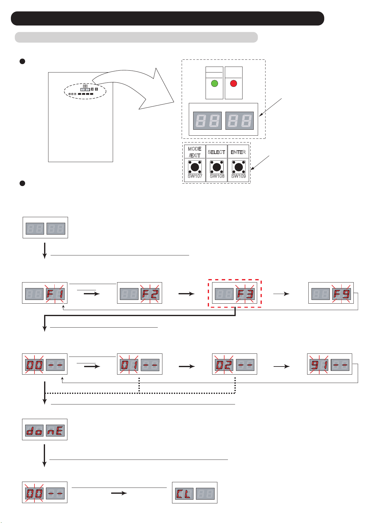
1-4-1 Test Run From Outdoor unit PC Board
All the indoor units connected to the outdoor unit can be test-operated by push button setting. (Only for master unit)
SWITCH POSITION
POWER
MODE
ERROR
LED101
(GREEN)
LED102
(RED)
7 Segment
LED Lamp
LED105 LED104
MODE
/EXIT
SELECT ENTER
Push button switch
Outdoor unit printed circuit board
SW107 SW108 SW109
TEST RUN SETTING
For a detailed description of push button operation, refer to the [D&T manual Chapter 6. SYSTEM DESIGN]
< Monitoring condition >
LED105 LED104
(1) Press the MODE / EXIT button ( SW107 ) once.
< Mode select condition >
[ Monitoring mode ] [ Setting mode ] [ Error history mode ]
(2)Press SELECT
button
LED105 LED104LED105 LED104 LED105 LED104LED105 LED104
[ Function mode ]
(3) Press the ENTER button ( SW109 )
< Fuction select condition >
[ Cooling test run ]
LED105 LED104
(4)Press SELECT
button
(5) Hold down the ENTER button ( SW109 ) for at least 3 seconds.
< Pursuance completion >
LED105 LED104
(6) Press the ENTER button ( SW109 ) or Time out ( 5 seconds)
< Return to mode select condition >
LED105 LED104
(7) Press the MODE / EXIT button
[ Heating test run ]
LED105 LED104
< Return to monitoring condition >
LED105 LED104
[ Test run stop ]
LED105 LED104
example,
Normal indicate : [ Cooling mode ]
[ Central control setting
Forced reset ]
LED105 LED104
01-16
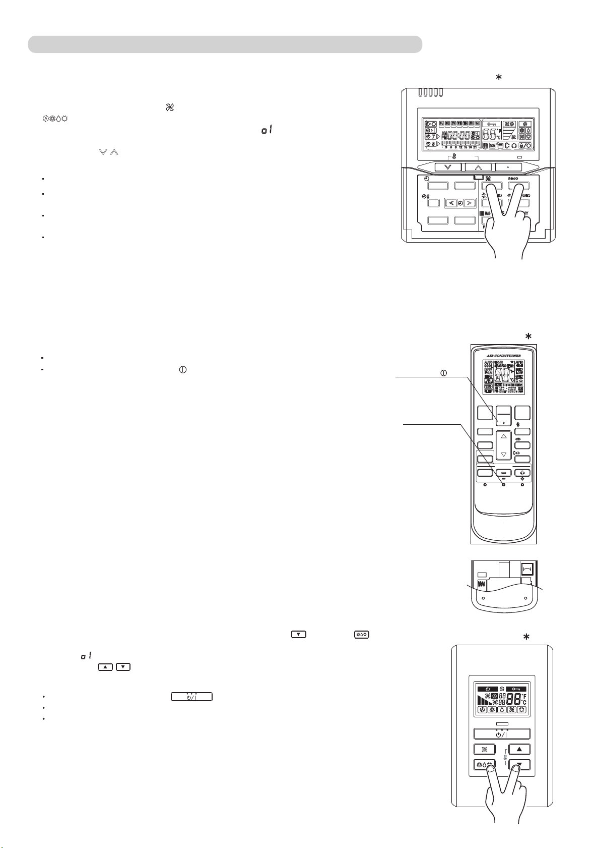
1-4-2 Test Run From Remote Controller
1. Standard wired remote controller
Stop the indoor unit. Push the button and
button simultaneously for more than two seconds.
The air conditioner will start to conduct a test run and " " will display on
the remote controller display.
However, the , setting button does not have function,
but all other buttons, displays, and protection functions will operate.
Perform the test operation for 60 minutes.
To stop test run, push the START / STOP button of the standard wired remote
controller.
For the operation method, refer to the operating manual and perform operation
check.
Check that there are no abnormal sounds or vibration sounds during test run
operation.
UTY - RNK
SET TEMP.
TIMER MODE DAY
SET BACK
DAY OFF
CLOCK ADJUST
TIMER DELETE TIMER SET
START / STOP
FAN MO DE
2. Standard wireless remote controller
Short two metal contacts under the battery compartment lid, while the air conditioner is running.
To stop test run operation, push button of the wireless
remote controller.
When the air conditioner is being test run, the OPERATION
and TIMER lamps of indoor unit flash slowly at the same time.
3. Simple remote controller
Stop the indoor and outdoor units. Push the remote controller
simultaneously for more than three seconds. The air conditioner will start to conduct a test
run and " " will display on the temperature display.
However the setting button does not have function but all other buttons,
displays and protection functions will operate.
button and
button
START/STOP button
Test run button
UTY - LNH
ON
OFF
ECONOMY
FILTER RESET
SET
TEMP.
SLEEP
TIMER
TIMER MODE
CLOCK
TEST
ADJUST
RUN
UTY - RSK
FANMODE
SET
SET
SWING
RESET
To stop test running press the button of the simple remote controller.
For the operation method refer to the operating manual and perform operation check.
Check that there are no abnormal sounds or vibration sounds during test run operation.
01-17
SET
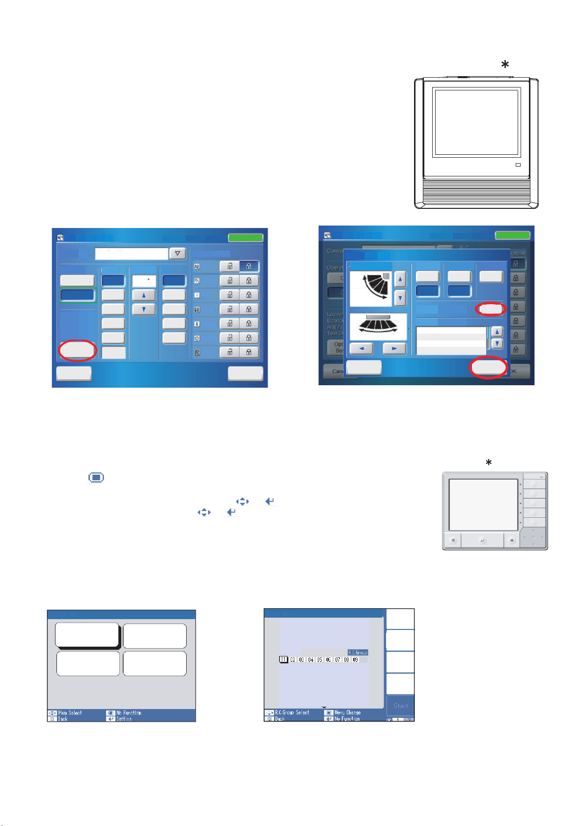
4. Touch panel controller
(1) Select the objective you want to test run.
Select the objective icon or list at the monitor screen. (Multiple selections is possible)
Select all the devices registered as objectives by pressing "Select All" on the monitor screen.
(2) After objective selection at (1), switch to the <Setting screen> by pressing "Operation".
(3) Switch to the <Detail setting screen > by pressing "Optional setting" on the setting screen,
(4) Press "Start" button and OK on the details setting screen.
Test run continues for 60 minutes.
To interrupt test run, select the device being the test run and excute an operation stop.
At the monitor screen, test run can cancel by selecting objective device and press OFF.
UTY - DTG
<Setting screen>
Operation Setting
Control Unit :
operation
On
On
Off
Off
Air Flow Direction
Economy
Anti Freeze
Filter Sign
Test Operation
Optional
Setting
Cancel
Cancel
Meeting Room
Mode Set Temp. Fan
Auto
24.0 C
Cool
Dry
Fan
Heat
Operation
Controlled
10/11.2008.Mar. 02:20 PM
R/C Prohibition
All
Auto
High
Med
Low
Quiet
On/Off
On
Mode
Temp.
Timer
Filter
Status: On
OK
OK
<Detail Setting screen>
5. Central remote controller
(1) Press " " button.
(2) Press "Set up Menue" and input password.
(3) Select "Indoor unit special setting" by presing or button.
(4) Select "Test operation by presing" or button
(5) Press the "Select ALL button" or "ldentify unit" button
[ Select All ]: All of R.C.Group (Indoor units)
[ Identify Unit ] : Specific R.C.Group (Indoor unit)
(6) Press the " Start " button
The test run continues for 60 minutes.
To interrupt test run before it is complet, return to the "Monitor Mode Screen",
and press ON/ OFF.
Indoor unit Special Setting
Test Operation
Indoor Unit
Set Temp. Range
05/31 03:59
Filter Sign
R.C. Prohibition
Test Operation
RCG_05
Operation Setting
SettingOptional
Air Flow Direction
Up
1
2
Swing
Left Right
1
2
Swing
Cancel
05/31 03:59
3
Down
3
4
5
4
Group
Select
All
Identify
Unit
Clear
Unit
10/11.2008.Mar. 02:20 PM
Economy
Test
Special State
Anti Freeze
On
Off
Stand by (Defrost)
Stand by (Oil Recovery)
Test Operation
On
Off
Operation
UTY-DCG
Status: On
Filter Sign
Reset
Start
OK
01-18
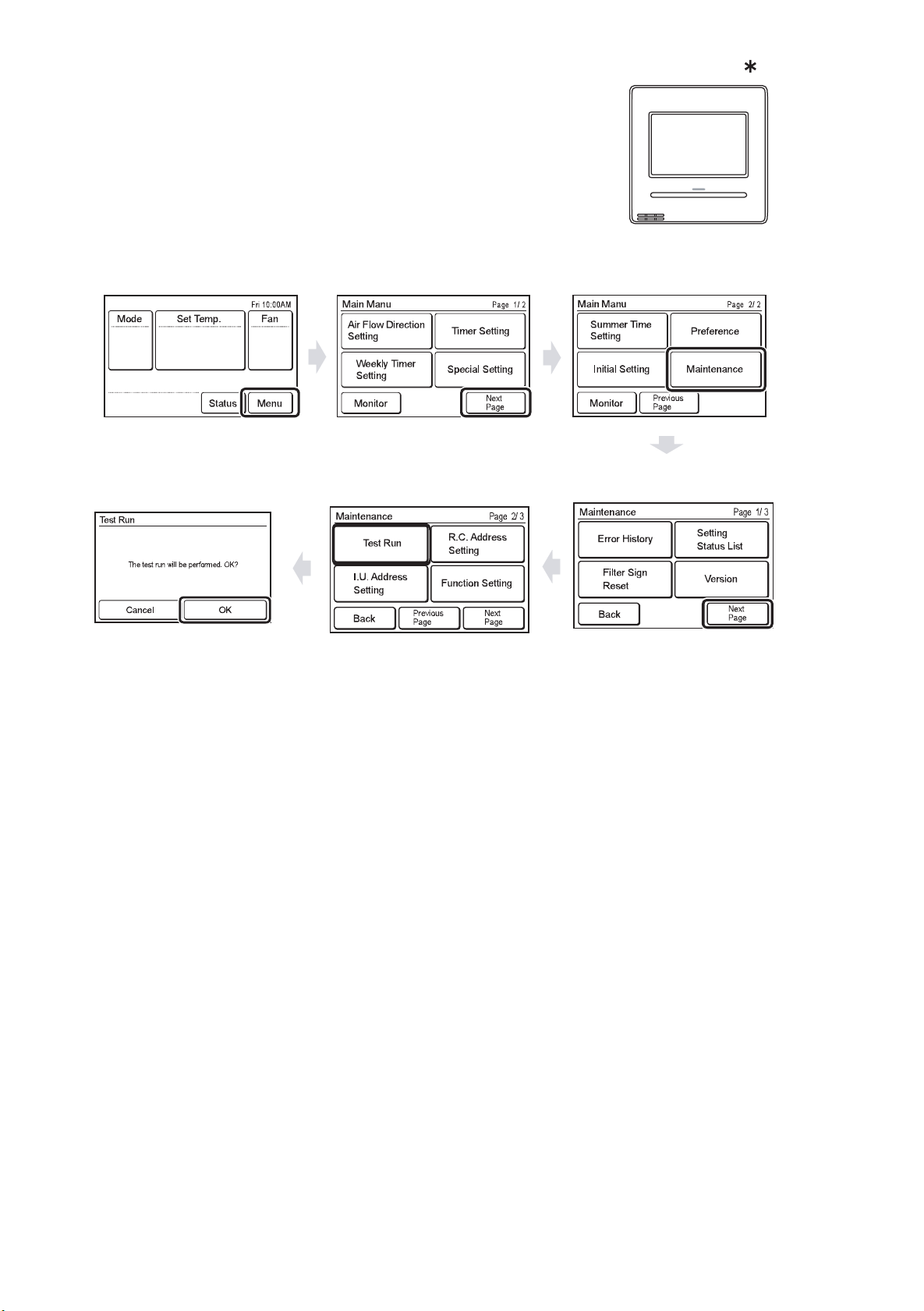
6. 2-wire type wired remote controller
(1) Press "Menu" on the monitor screen. the < Main Menu screen > is displayed.
(2) Press "Next Page" and press "Maintenance"
(3) Press "Next Page" and press "Test Run". the <Test run screen > is displayed.
(4) Press "OK"
The test run continues for 60 minutes.
To interrupt test run before it is complet, return to the "Monitor Mode Screen",
and press ON/ OFF.
< Monitor Mode Screen >
< Main Manu Screen >
UTY - RNR
< Test Run Screen >
< Maintenance Screen >
01-19
1-5 TEST RUN CONTROL
1. When the test run signal is transmitted from standard wired, wireless remote controller,
simple remote controller, transmitted netwwork, and outdoor unit.
(1) The test run operation starts and the electric expansion valve is controlled to a maximum flow, regardless of
the temperature condition.
(2) Frost prevention operation has priority over item(1).
(3) Whether state of the indoor unit operates or stops, All units in the same refrigerant circuit will start to conduct a
test run in accordance with the operation mode set by push switch of outdoor unit ( see 1 - 2 - 3 ).
(4) After 60 minutes passes, the test run stops.
(5) Test running initialization is shown below.
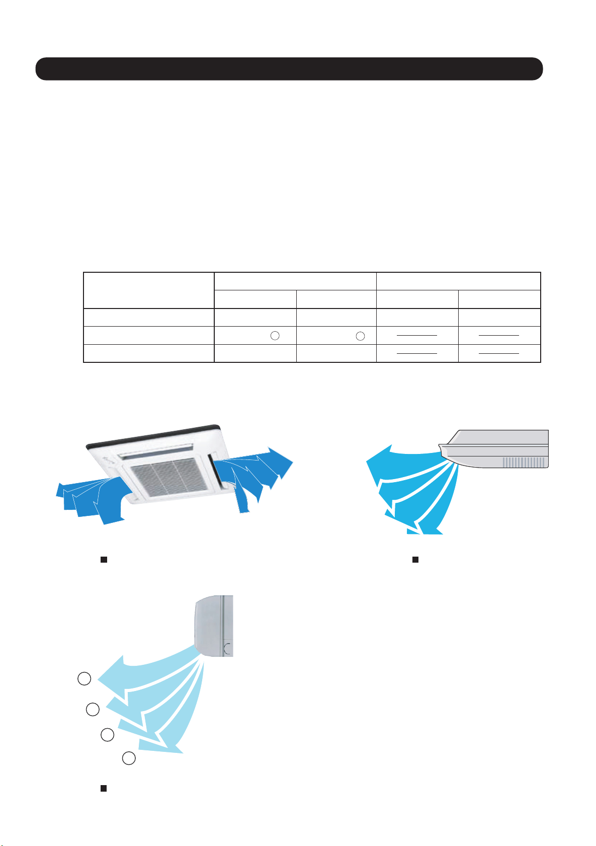
* The temperature controlling on the test run operates regardless of setting temperature.
Operating Mode
Fan speed Hi Hi Hi Hi
Vertical Air Direction Panel
Swing
*EXAMPLE
1
2
3
4
EXCEPT FOR THE DUCT MODEL DUCT TYPE
Cooling Heating Cooling Heating
1
Position
4
1
2
3
Position
4
1
OFF OFF
2
3
4
COMPACT CASSETTE TYPE
CEILING TYPE
1
2
3
4
COMPACT WALL MOUNTED TYPE
01-20
1-6 Field Setting And Monitor Mode List for Outdoor unit
Push switch on
outdoor unit PCB
Monitoring mode
[ F1 ]
Classification
Device and
system
Operation of
each part
Time guard 20 Accumulated current time
Refrigerant
cycle data 1
Refrigerant
cycle data 2
Refrigerant
cycle data 3
ITEM
CODE No.
Connected number of indoor unit
00
Software version of outdoor unit
01
02 Software version of INV PCB
03 Software version of communication PCB
10 Rotational speed of outdoor unit fan motor
11 Rotational speed of INV compressor
12 Current value of INV compressor Current value of INV compressor is displayed
14 Pulse of EEV1 Pulse of EEV1 is displayed
15 Pulse of EEV2 Pulse of EEV2 is displayed
16 Pulse of EEV3 Pulse of EEV3 is displayed
21 INV compressor accumulated time [ Cooling ]
INV compressor accumulated time [ Heating ]
22
30 Information on Thermistor 1
( Discharge temperature sensor 1)
31 Information on Thermistor 2
( Outdoor temperature sensor )
Information on Thermistor 3
32
( Suction temperature sensor )
Information on Thermistor 4
33
( Liquid temperature sensor 1)
34 Information on Thermistor 5
(Liquid temperature sensor 2)
35 Information on Thermistor 6
( Sub-cool H-Ex (outlet) sensor )
36 Information on Thermistor 7
(Heat exchanger 1 gas sensor1)
37 Information on Thermistor 8
(Heat exchanger 2 gas sensor2)
38 Information on Thermistor 9
(Heat exchanger 1 liquid sensor)
39 Information on Thermistor 10
(Heat exchanger 2 liquid sensor)
40 Information on Thermistor 11
(Compressor temperature sensor)
50 Information on pressure sensor 1
( High pressure sensor )
51 Information on pressure sensor 2
( Low pressure sensor )
Setting Mode
Information contents
The number of the communicating unit is displayed
Software version :
[ ] [ ] [ ] [ ] [ ] displays by five items
It skips when there is no suffix
The rotational speed of the outdoor unit fan motor is displayed
[ 0 ~ 999 ] rpm
The rotational speed of the compressor is displayed
[ 0 ~ 999 ] rps
[ 0.00 ~99.99 ] A
[ 0 ~ 9999 ] pls
[ 0 ~ 9999 ] pls
[ 0 ~ 9999 ] pls
Accumulated current time is displayed
[ 0 ~ 9999 ]
Accumulated time is displayed in the cooling operation of the
INV compressor
[ 0 ~ 9999 ]
Accumulated time is displayed in the heating operation of the
INV compressor
[ 0 ~ 9999 ]
The value of the Thermistor 1 is displayed
[ -99.9 ~ 999.9 ]
[ -99.9 ~ 999.9 ] °C or °F
The value of the Thermistor 2 is displayed
[ -99.9 ~ 999.9 ] °C or °F
[ -99.9 ~ 999.9 ] °C or °F
The value of the Thermistor 3 is displayed
[ -99.9 ~ 999.9 ] °C or °F
The value of the Thermistor 4 is displayed
[ -99.9 ~ 999.9 ] °C or °F
The value of the Thermistor 5 is displayed
[ -99.9 ~ 999.9 ] °C or °F
The value of the Thermistor 6 is displayed
[ -99.9 ~ 999.9 ] °C or °F
The value of the Thermistor 7 is displayed
[ -99.9 ~ 999.9 ] °C or °F
The value of the Thermistor 8 is displayed
[ -99.9 ~ 999.9 ] °C or °F
The value of the Thermistor 9 is displayed
[ -99.9 ~ 999.9 ] °C or °F
The value of the Thermistor 10 is displayed
[ -99.9 ~ 999.9 ] °C or °F
The value of the Thermistor 11 is displayed
[ -99.9 ~ 999.9 ] °C or °F
The value of the pressure sensor 1 is displayed
If unit is [MPa], it is displayed as [ 0.00 ~ 9.99 ]
[psi], it is displayed as [ 0.0 ~ 999.9 ]
The value of the pressure sensor 2 is displayed
If unit is [MPa], it is displayed as [0.00 ~ 9.99]
[psi], it is displayed as [ 0.0 ~ 999.9 ]
10hour
10hour
10hour
°C or °F
01-21
Push switch on
outdoor unit PCB
Setting mode
[ F2 ]
Install
Correction
Change of
function 1
Change of
function 2
ITEM
CODE No.
Pipe length setting
00
10
Sequential start shift
11
Cooling capacity shift
Heating capacity shift
12
13,14,15 Forbidden
20 Switching between batch stop or
emergency stop
22
Snow falling protection fan mode
23
Interval setting for snow falling
protection fan mode
24
High static pressure mode
25,26,27 Forbidden
Change of unit Temperature
28
Change of unit Pressure
29
30 Energy saving level setting
32,33 Forbidden
Presence of heater selection
35
control using outdoor temperature *1
Outdoor temperature zone
36
boundary temperature A*1
37 Outdoor temperature zone
boundary temperature B*1
Setting Mode
ITEM
CODE No.
131-213ft.(40-65m)
00
01 0-131ft.(0-40m)
02
213-295ft.(65-90m)
295-394ft.(90-120m)
03
394-492ft.(120-150m)
04
00
Normal
01
21sec. Delay
42sec. Delay
02
63sec. Delay
03
Normal mode
00
Save energy mode +4
01
High power mode 1 -4
02
High power mode 2 -7
03
Forbidden
04
00
Normal mode
01
Save energy mode -4
02
High power mode 1 +4
High power mode 2 +7
03
00
01
00
Batch stop
Emergency stop
01
Valid
00
01
Invalid
Standard (30min)
00
01
Short 1 (5min)
02
Short 2 (10min)
03
Short 3 (20min)
00
Standard
High static pressure 1 (equivalent to 0.12 in.WG /30Pa)
01
High static pressure 2 (equivalent to 0.32 in.WG /80Pa)
02
Forbidden
03
00
01
00
Celsius (°C)
Fahrenheit (
01
MPa
00
psi
01
00
Level 1 (stop)
01
Level 2 (operated at 40% capacity)
02
Level 3 (operated at 60% capacity)
03
Level 4 (operated at 80% capacity)
04
Level 5 (operated at 100% capacity)
00
01
No
00
Yes
01
00
01
02
03
04
05
06
07
08
00
01
02
03
04
05
06
07
08
09
10
11
12
13
14
15
°
F(-20
-4.0
-0.4°F(-18
-3.2°F(-16
6.8°F(-14
10.4°F(-12
14.0°F(-10
17.6°F(-8
21.2°F(-6
24.8°F(-4
°
F(6
42.8
14.0°F(-10
17.6°F(-8
21.2°F(-6
24.8°F(-4
28.4°F(-2
32.0°F(0
35.6°F(2
39.2°F(4
42.8°F(6
46.4°F(8
50.0°F(10
53.6°F(12
57.2°F(14
60.8°F(16
64.4°F(18
°C)
°C)
°C)
°C)
°C)
°C)
°C)
°C)
°C)
°C)
°C)
°C)
°C)
°C)
°C)
°C)
°C)
°C)
°C)
°C)
°C)
°C)
°C)
°C)
°C)
Setting Function DefaultClassification
°
F(+2°C)
°
F(-2°C)
°
F(-4°C)
°
F(-2°C)
°
F(+2°C)
°
F(+4°C)
°F
)
01-22
Push switch on
outdoor unit PCB
Setting mode
[ F2 ]
Low noise
setting 1
Change of
function 3
Change of
function 4
ITEM
CODE No.
40
Capacity priority setting
(in low noise mode)
Setting Mode
41 Low noise mode setting 00
Low noise mode operation
42
level setting
Back up operation
60
61,62,63
Forbidden
70 Electricity meter No. setting 1
(Set the ones digit and tens digit of the No
of the electricity meter connected to CN135.)
71 Electricity meter No. setting 2
(Set the hundreds digit of the No. of the
electricity meter connected to CN135.)
72 Electricity meter pulse setting 1
(Set the ones digit and tens digit of the No. of
the electricity meter pulse setting connected
to CN135.)
73 Electricity meter pulse setting 2
(Set the hundreds digit and thousands digit
of the electricity meter pulse setting connected
to CN135.)
ITEM
CODE No.
00 Off (quiet priority)
On (capacity priority)
01
Off (Normal)
On (Low noise mode operation is always done)
01
Level 1 (55dB)
00
Level 2 (50dB)
01
00*2
On
Off
01*3
00
On
Off
01
Setting Function DefaultClassification
00~99*4Setting number x00~x99
( Refer to Design & Technical Manual for details.)
00~02*4Setting number 0xx~2xx
( Refer to Design & Technical Manual for details.)
00~99*5Setting number xx00~xx99
( Refer to Design & Technical Manual for details.)
00~99*5Setting number 00xx~99xx
( Refer to Design & Technical Manual for details.)
*1 : Do not set this for outdoor units with Slave setting.
*2 : If one of compressor fails, backup operation will be performed by the remaining compressors.( For starting the system SET4-2 switching is required)
*3 : If one of compressor fails, all units will be abnormal stop.
*4 : When electricity meter No. is set to "000" and "201 to 299", the pulses input to CN135 become ineffective.
Available setting number is "001" to "200"
*5 : When the electricity meter pulse setting is set to "0000", the pulses input to CN135 become ineffective.
Available setting number is "0001" to "9999"
00
00
00
00
01-23
Push switch on
outdoor unit PCB
Function mode
[ F3 ]
Classification
Forced
operation
Install and
maintenance 1
Install and
maintenance 2
Clear Error history clear
ITEM
CODE No.
00
01
02
03,04
10
11
22
21
30
31
32
Setting Mode Setting Function
Cooling test run
Heating test run Forced thermostat-ON in Heating
Test run stop Test run is stopped
Forbidden
Signal amplifier automatic address
Indoor unit automatic address
RB unit automatic address
Vacuuming mode
Forbidden
Current time clear Accumulated current time becomes [ 0 ]
Forced thermostat-ON in Cooling
Automatic address setting operates for signal amplifier
Automatic address setting operates for indoor unit of same
refrigerant circuit
Automatic address setting operates for RB unit of same
refrigerant circuit
Vacuuming mode operates
Refer to page 01-01 for the function
All the abnormal code histories are cleared
Push switch on
outdoor unit PCB
Error history mode
[ F9 ]
INV compressor accumulated time clear
33
Field setting all clear Return to default the all set items
35
Abnormal Abnormal reset
Specialty
function
Error history
40
91
ITEM
CODE No.
00
01
02
03
04
05
06
07
08
09
*
Forced Central control function forced release When the centralized control device failure, and the centralized
Meaning of Error History Number
1 time ago (Newest) When the error occurred, the error code is memorized up to
2 times ago
3 times ago
4 times ago
5 times ago
6 times ago
7 times ago
8 times ago
9 times ago
10 times ago (Oldest)
Accumulated time of the INV compressor becomes [ 0 ]
It was displayed when abnormality occurs, and abnormal
code is reset
This is a function that uses to clear abnormal display
after the repair is completed
Please operate the switch after power off or
power on the outdoor unit
control setting cannot be released, this function is used
All the limitations set with the centralized control device are
released
Information contentsClassification
10 on Main PCB.
If the memorized error code becomes over 10, the oldest one
will be erased.
Refer to Chapter TROUBLE SHOOTING
Error Code List of Outdoor unit
01-24
<< Error code which manual error release will be required >>
A5.1 Low pressure abnormal
84.1 Current sensor 1 error
93.1 Inverter compressor start up error
94.1 Trip detection
A1.1 Discharge temperature 1 abnormal
A3.1 Compressor 1 temperature abnormal
97.1 Outdoor unit fan motor lock error
97.5 Fan motor temperature abnormal
97.9 Fan motor driver abnormal
68.2 Rush current limiting resister temp rise protection
95.5 Compressor motor loss of synchronization
A6.3 Outdoor heat exchanger 1 gas temperature abnormal
A6.4 Outdoor heat exchanger 2 gas temperature abnormal
 Loading...