

Page 1

CONTENTS
SPECIFICATIONS
. . . . . . . . . . . . . . . . . . . . . . . . . . . . . . . .
1
OUTLINE AND DIMENSIONS
. . . . . . . . . . . . . . . . . . . . .
2
REFRIGERANT SYSTEM DIAGRAM
. . . . . . . . . . . . . .
4
ERROR DISPLAY
. . . . . . . . . . . . . . . . . . . . . . . . . . . . . . .
7
CIRCUIT DIAGRAM
. . . . . . . . . . . . . . . . . . . . . . . . . . . . . .
5
PCB CIRCUIT DIAGRAM
. . . . . . . . . . . . . . . . . . . . . . . .
13
DISASSEMBLY ILLUSTRATION (Indoor Unit)
. . . . .
14
DISASSEMBLY ILLUSTRATION (Outdoor Unit)
. . . .
21
PARTS LIST (Indoor Unit)
. . . . . . . . . . . . . . . . . . . . . . . .
26
PARTS LIST (Outdoor Unit)
. . . . . . . . . . . . . . . . . . . . . .
28
ACCESSORIES
. . . . . . . . . . . . . . . . . . . . . . . . . . . . . . . . . .
30
SPLIT TYPE
ROOM AIR CONDITIONER
FLOOR CONSOLE /
UNDER CEILING
DUAL type
Models
Indoor unit
Outdoor unit
ABU18RULX
ABU24RULX
AOU18RLX
AOU24RLX
Page 2

SPECIFICATIONS
TYPE
INDOOR UNIT
OUTDOOR UNIT
COOLING CAPACITY
17,800 / 17,800 BTU/h
POWER SOURCE
FREQUENCY
RUNNING CURRENT (Heat)
INPUT WATTS (Heat)
E.E.R. (Heat)
MOISTURE REMOVAL
AIR CIRCULATION-Hi
(m /hr)
( /hr)
ELECTRICAL DATA
COMPRESSOR
DIMENSIONS
TYPE
Hermetic type, 4 poles, Inverter, Twin Rotary
DISCRIMINATION
REFRIGERANT
R410A
POWER SOURCE
DISCRIMINATION
INDOOR UNIT
( Cool / Heat )
HIGH-SPEED
MED-SPEED
LOW-SPEED
DISCRIMINATION
OUTDOOR UNIT
( Cool / Heat )
HIGH- SPEED
INDOOR UNIT
H x W x D
7-7/8" x 39-1/8" x 25-7/8" inch
199 x 990 x 655 mm
OUTDOOR UNIT
FAN MOTOR
WEIGHT
INDOOR UNIT
Gross / Net
H x W x D
Gross / Net
OUTDOOR UNIT
2.5 L/hr
Cool and Heat
ABU18RULX
AOU18RLX
9.8 A / 10.9 A
2.25 kW / 2.25 kW
2.80 / 2.80 kW/kW
780 m3/hr
TNB220FPBM9
4 lb 3 oz (1,900 g)
1,060 / 1,060 r.p.m.
890 / 890 r.p.m.
770 / 770 r.p.m.
MFE-45ROM
780 / 780 r.p.m.
MFE-45ROM
850 / 900 r.p.m.
32-3/4" x 35-1/2" x 13" inch
900 x 900 x 350 mm
ABU24RULX
AOU24RLX
22,200 / 22,200 BTU/h
230 V / 208 V
10.2 A / 11.3 A
2.33 kW / 2.33 kW
3.05 / 3.05 kW/kW
880 m3/hr
230 V
MFA-24PPTMFA-24PPT
1,180 / 1,100 r.p.m.
1,000 / 1,000 r.p.m.
900 / 900 r.p.m.
37 kg / 28 kg
70 kg / 64 kg
3.5 L/hr
HEATING CAPACITY
21,500 / 21,500 BTU/h 24,200 / 24,200 BTU/h
RUNNING CURRENT (Cool)
7.1 A / 7.9 A 9.8 A / 10.9 A
INPUT WATTS (Cool)
1.63 kW / 1.63 kW 2.25 kW / 2.25 kW
E.E.R. (Cool)
3.19 / 3.19 kW/kW 2.89 / 2.89 kW/kW
12005.12.28
49 ft. (15 m)
66 ft. (20 m)
98 ft. (30 m)
ADDITIONAL REFRIGERANT
4 lb 3oz (1,900 g)
4 lb 7oz (2,000 g)
4 lb 14oz (2,200 g)
0.215oz / ft. (20 g / m)
131 ft. (40 m)
5 lb 5oz (2,400 g)
164 ft. (50 m)
5 lb 12oz (2,600 g)
4 lb 3oz (1,900 g)
4 lb 10oz (2,100 g)
5 lb 8oz (2,500 g)
6 lb 6oz (2,900 g)
7 lb 5oz (3,300 g)
0.424 oz / ft. (40 g / m)
FULL CHARGE AMOUNT
REFRIGERANT CHARGE (R410A)
Pipe Length
1 60 Hz
Page 3

OUTLINE AND DIMENSIONS
INDOOR UNIT
Unit : inch (mm)
39-1/8" (990)
900
19-3/4" (500)
25-7/8" (655)
530
200175
7-7/8" (199)
(rear view)
22005.12.21
Models :
ABU18RULX, ABU24RULX
Page 4
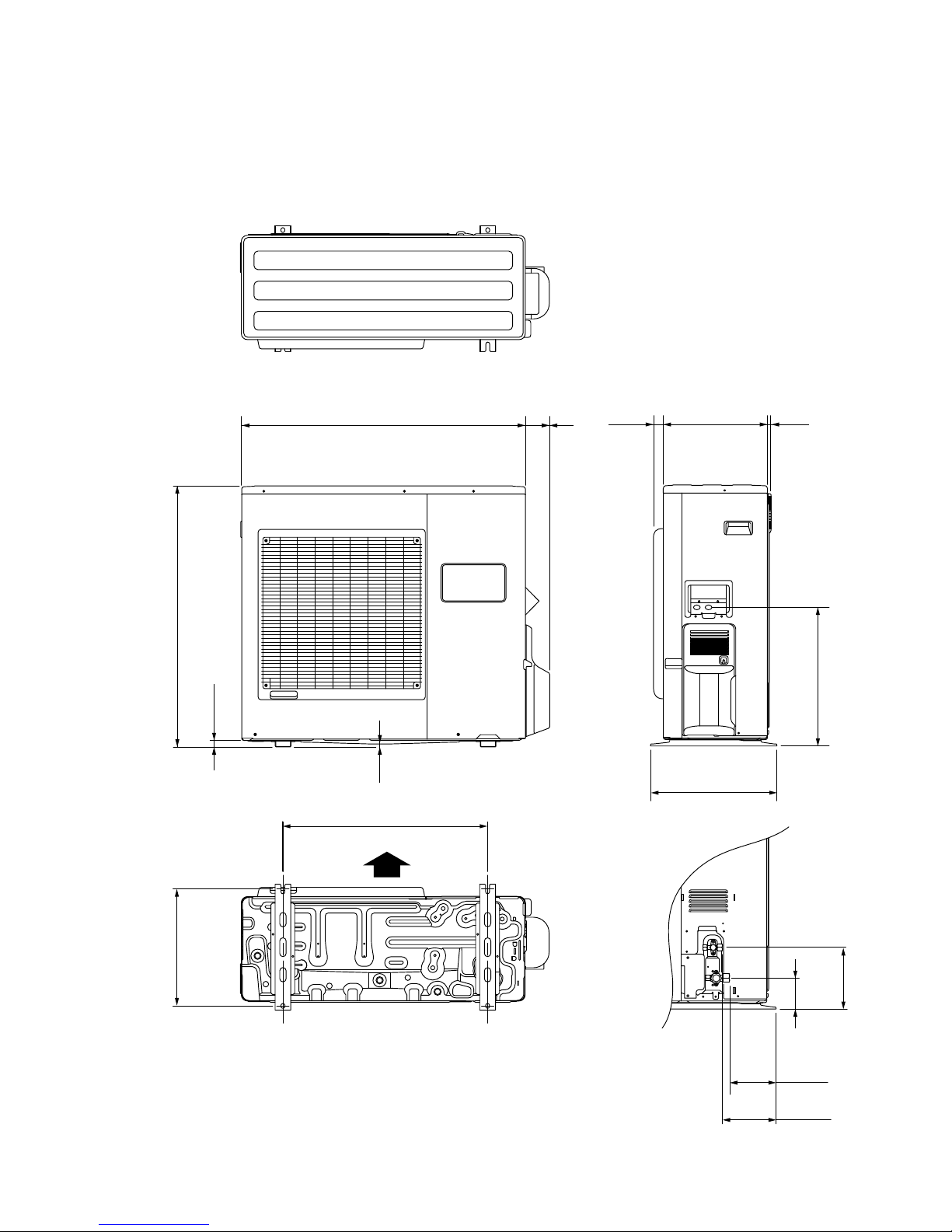
Unit : inch (mm)
OUTDOOR UNIT
Models:
AOU18RLX, AOU24RLX
3"(77)
35-1/2" (900)
32-3/4" (830)
17-3/8" (440)
7/8" (21)
3/8"
(9)
15-3/4" (400)
13" (330)
1-1/4"
(31)
1/2"
(12)
7-3/4" (196)
5-3/4" (147)
6-3/4" (170)
3-7/8"
(99)
14-5/8" (370)
25-5/8" (650)
Air Flow
32005.12.28
Page 5

Evaporator
REFRIGERANT SYSTEM DIAGRAM
OUTDOOR UNIT
Pressure
Check Valve
Condenser
4-way
Valve
High Pressure
Switch
Accumulator
Muffler
Compressor
Expansion
Valve
Refrigerant Pipe
6.35mm (1/4")
Charging Valve
Charging
Valve
Refrigerant Pipe
12.7mm (1/2")
INDOOR UNIT
Strainer
Strainer
: COOL
: HEAT
Models :
ABU18RCLX / AOU18RLX
Evaporator
OUTDOOR UNIT
Pressure
Check Valve
Condenser
4-way
Valve
High Pressure
Switch
Accumulator
Muffler
Compressor
Expansion
Valve
Refrigerant Pipe
9.52mm (3/8")
Charging Valve
Charging
Valve
Refrigerant Pipe
15.88mm (5/8")
INDOOR UNIT
Strainer
Strainer
Models :
ABU24RULX / AOU24RLX
42005.12.28
Page 6
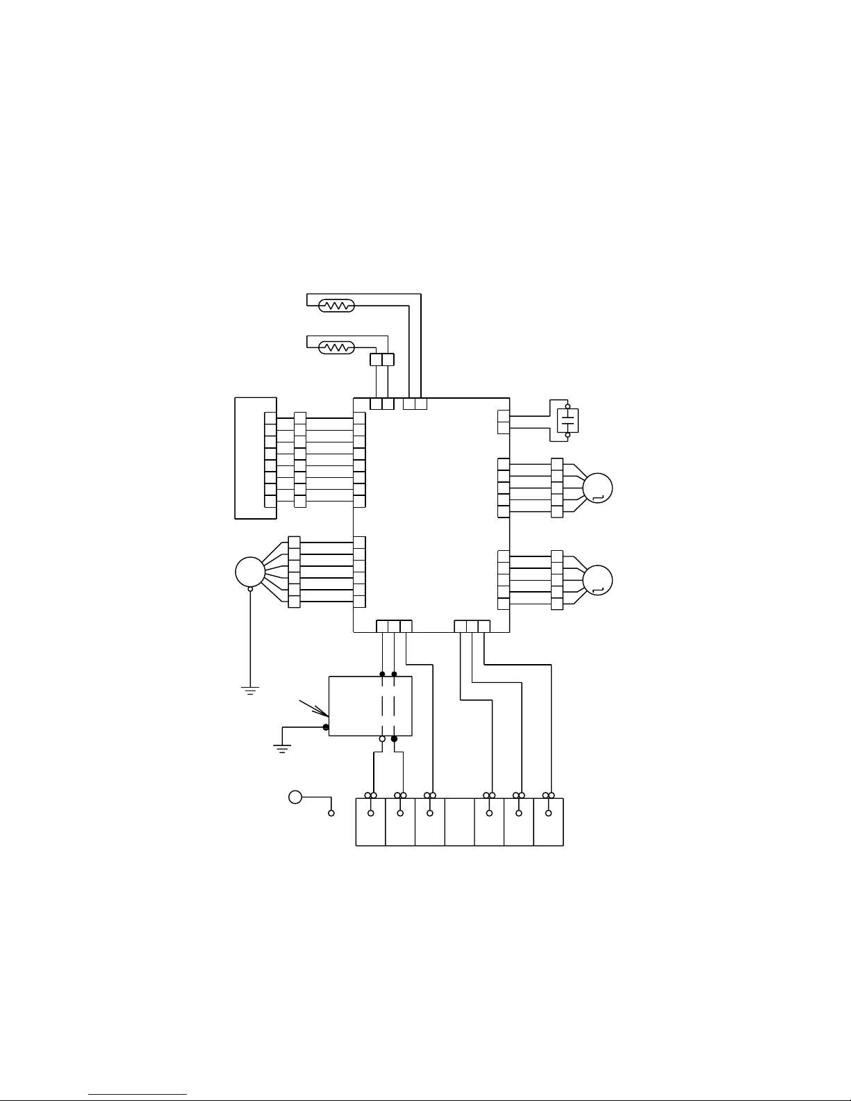
CIRCUIT DIAGRAM
Models :
ABU18RULX, ABU24RULX
TERMINAL
STEP MOTOR
( LEFT / RIGHT )
STEP MOTOR
( UP / DOWN )
FAN MOTOR
CAPACITOR
FAN MOTOR
ROOM TEMPERATURE THERMISTOR
PIPE TEMPERATURE THERMISTOR
F M
M
M
1
2
3 1
2
3
Use T3.15A-250V
Fuse on F101
G
L
N
PURPLE
BLUE
PINK
RED
WHITE
BLACK
BLACK
WHITE
RED
GREEN
GRAY
PURPLE
BLUE
WHITE
YELLOW
ORANGE
RED
BROWN
WHITE
WHITE
BROWN
RED
ORANGE
YELLOW
WHITE
BLACK
BLACK
GRAY
GRAY
BROWN
RED
ORANGE
YELLOW
WHITE
BLACK
BLACK
WHITE
WHITE
RED
CN7 CN8
CN1 CN17
CN13CN5
CN11
CN10 CN4
CN201
GREEN / YELLOW
1
7
6
5
4
3
2
8
1
6
5
4
3
2
1
7
6
5
4
3
2
8
1
7
6
5
4
3
2
8
1
6
5
4
3
2
1
5
4
3
2
1
5
4
3
2
1
5
4
3
2
1
5
4
3
2
1
1
2
1
2
1
2
2
1 2 3
1 2 3
INDICATOR PCB ASSY
CONTROLLER PCB ASSY
POWER SUPPLY PCB
52005.12.28
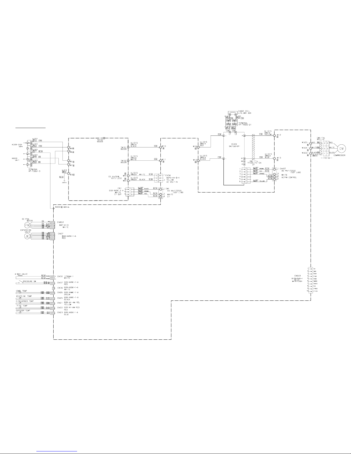
Page 7
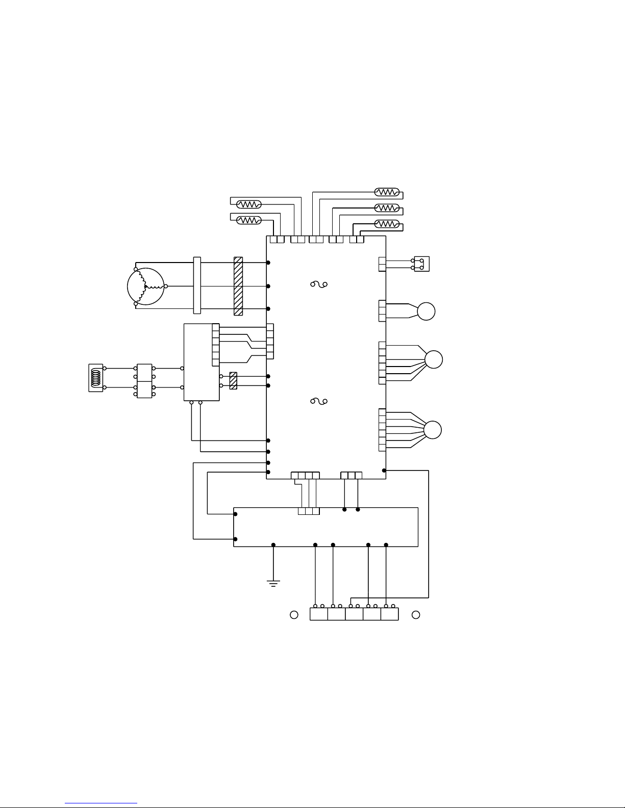
Model :
AOU18RLX, AOU24RLX
ORANGE
YELLOW
WHITE
BLUE
BROWN
RED
BLUE
YELLOW
WHITE
BLACK
RED
BLACK
BLACK
RED
RED
BLACK
BROWN
BLUE
BROWN
BLACK
RED
BROWN
BLACK
BLACK
WHITE
BLACK
BLACK
WHITE
WHITE
GREEN
BLACK
WHITE
BLACK
RED
YELLOW
BLUE
YELLOW
ORANGE
RED
BROWN
BLACK
BLACK
WHITE
BROWN
BLACK
BLACK
WHITE
WHITE
RED RED
RED
CN1
CN1
CN34
W9 W8
W200
W11
W10
W17
W16
CN27
CN802
W12
W13
CN407
CN30
CN37
W303
W304
W305
CN21
CN22
CN23
CN26
CN25
1
6
5
4
3
2
1
432
1
6
5
4
3
2
1
5
4
3
2
1
3
2
1
2
1
32
1 2 1 2 1 2 1 2 1 2
1
6
5
4
3
2
1
32
TM102
TM101
W3
W6 W7
W4
W5
G G
2 (N)
1 3
L
N
EARTH EARTH
EXPANSION VALVE COIL
E V
F M FAN MOTOR
SOLENOID COIL
4WV
HIGH PRESSURE SWITCH
FUSE
F4 T 5A-250V
FUSE
F2 T 3.15A-250V
EMI FILTER
2T
L1
L2
P
N
+
-
TERMINAL
CHOKE COIL
COMPRESSOR
CONNECTOR
EMI FILTER
1T
U
V
W
W
U
V
DISCHARG TEMPERATURE
THERMISTOR
PIPE TEMPERATURE
THERMISTOR
OUTDOOR TEMPERATURE
THERMISTOR
COMPRESSOR TEMPERATURE
THERMISTOR
HEAT SINK TEMPERATURE
THERMISTOR
POWER SUPPLY PCB ASSY
CONTROLLER PCB ASSY
ACTIVE
FILTER
MODULE
62005.12.28
Page 8
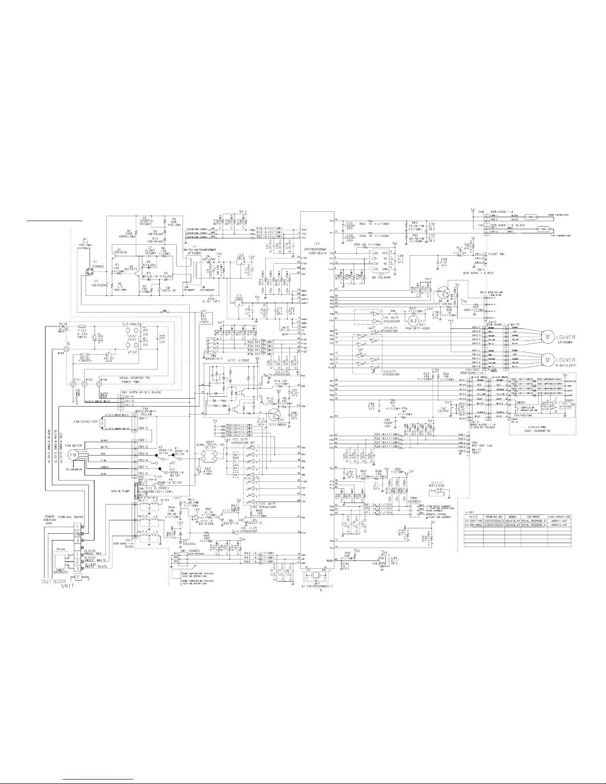
Models :
ABU18RULX
ABU24RULX
CONTROLLER PCB ASSY
ABU18RULX : K01AL-050PHSE-C1
ABU24RULX : K01AL-050SHSE-C1
INDOOR PCB CIRCUIT DIAGRAM
72005.12.28
Page 9
Models :
AOU18RLX
AOU24RLX
POWER SUPPLY PCB ASSY
K04BA-0500HUE-P0
CONTROLLER PCB ASSY
AOU18RLX : K04AW-0503HUE-C1
AOU24RLX : K04AW-0502HUE-C1
INVERTER ASSEMBLY
AOU18RLX : EZ-005GHUE
AOU24RLX : EZ-005FHUE
OUTDOOR PCB CIRCUIT DIAGRAM
82005.12.28
Page 10

600/450V x 4
Models : AOU18RLX, AOU24RLX
CONTROLLER PCB ASSEMBLY ( MAIN PCB )
AOU18RLX : K04AW-0503HUE-C1
AOU24RLX : K04AW-0502HUE-C1
92005.12.28
Page 11

5V
TM101
TM102
C112
0.015
<YE>
C113
0.015
<YE>
C111
3.3
<LE>
L4
RCH4730-021PF07
C107
3.3
<LE>
TM100
L2
N200500K1D7C
CT1
CT-1B
5V
D60
DAN217U
C64
0.1
<F>
R68 22K
<1/10W>
C65
0.1
<F>
VR1
B2K
+
R61 3.74K
<1/10W>
(1%)
C60
220/16V
<PJ>
R60 1.0K
<1/10W>
(1%)
SA100
RA-302M
C106
3.3
<LE>
C104
0.033
<YE>
C105
0.033
<YE>
C101
3.3
<LE>
VA101
470V
<TNR>
VA102
470V
<TNR>
B
B
B
B
B
B
B
BLACK
WHITE
TO INDOOR UNIT
POWER SOURCE
230V
60Hz
EARTH
AC VOLT OUT
W2
W5
W6
BLACK
WHITE
W7
GREEN
W3
W8
BLACK
WHITE
W9
W1
W4
L1
RCH4730-021PF07
CN1
B3B-XASK-1-A
WHITE
CT OUT
1
2
3
or
or
AOU18RLX, AOU24RLX : W4 and W5
AOU36RLX, AOU42RLX : W1 and W2
*
*
*
POWER SUPPLY PCB ASSEMBLY
K04BA-0500HUE-P0
2005.12.28 10
Models : AOU18RLX, AOU24RLX
Page 12

ERROR CONTENTS
(Indoor unit)
Indoor EEPROM abnormal
Outdoor EEPROM abnormal
Indoor room temperature sensor open
Indoor room temperature sensor shortcircuited
Indoor heat exchanger temperature sensor open
Indoor heat exchanger temperature sensor shortcircuited
Float switch operated
Indoor signal abnormal
Outdoor signal abnormal
Indoor fan abnormal
Outdoor power source connection abnormal
Outdoor heat exchanger temperature sensor open
Outdoor heat exchanger temperature sensor shortcircuited
Outdoor temperature sensor open
Outdoor temperature sensor shortcircuited
Outdoor discharge pipe temperature sensor or compressor
temperature sensor open
Outdoor discharge pipe temperature sensor or compressor
temperature sensor shortcircuited
Outdoor high pressure abnormal
Outdoor discharge pipe temperature or compressor
temperature sensor abnormal
OPERATION
lamp (RED)
(2 times)
(2 times)
(3 times)
(3 times)
(4 times)
(5 times)
(5 times)
(6 times)
TIMER lamp
(GREEN)
(2 times)
(3 times)
(3 times)
(4 times)
(4 times)
(5 times)
(5 times)
(6 times)
(7 times)
SWING lamp
(ORANGE)
: 0.1s ON/0.1s OFF (flash) : OFF
: 0.5s ON/0.5s OFF (flash)
Error contents
SWING SWING TIMER
MANUAL
AUTO
OERATION
VERTICAL SWING lamp (Orange)
TIMER lamp (Green)
OPERATION lamp (Red)
Operation can be checked by lighting and flashing of the display section OPERATION,
TIMER, and VERTICAL SWING lamps.
Perform judgment in accordance with the following.
TEST RUNNING
When the air conditioner is run by pressing the remote control unit test run button, the
OPERATION, TIMER, and VERTICAL SWING lamps flash slowly at the same time.
ERROR
The OPERATION, TIMER, and VERTICAL SWING lamps operate as follows (Table 1)
according to the error contents.
112005.12.28
Page 13

SPECIAL INSTALLATION
SETTING
PUMP DOWN (Refrigerant collecting operation)
ERROR CONTENTS
(outdoor unit)
1. Make a TEST RUN in accordance with the in stallation instruction sheet for the indoor unit.
2. OUTDOOR UNIT LEDS
Error contents
Communication error
(Indoor unit - Outdoor unit)
Discharg pipe temperature sensor
Outdoor heat exchanger temperature sensor
Outdoor temperature sensor
Compressor temperature sensor
Heat sink temperature sensor
Pressure switch abnormal
IPM error
Compressor rotor position cannot detect
Compressor cannot operate
Outdoor fan abnormal (upper fan)
Outdoor fan abnormal (lower fan)
No error
LED
1 flash
2 flash
3 flash
4 flash
7 flash
8 flash
9 flash
12 flash
13 flash
14 flash
15 flash
16 flash
lighting
1. When the product is stopped:
When a malfunction occurs in the outdoor unit, the LED on
the circuit board lights to indicate the error. Refer to the following table for the description of each error according to the
LED.
Per form t he following procedures to colle ct the refri gerant
when moving the indoor unit or the outdoor unit.
*When the pump down operation is repeated, temporarily disconnect
the power supply after opening the closed valves (both liquid and gas).
Reconnect the power supply after 2 - 3 minutes and perform the pump
down operation.
*When the start of the operation after pump down operation has been
completed, temporarily disconnect the power supply after opening the
closed valves (both liquid and gas).
Reconnect the power supply after 2-3 minutes and be sure to perform
a test operation for cooling.
1
2
3
4
2. When the product is operating:
1
2
3
4
Press the PUMP DOWN switch on the outdoor unit.
(The LED on the outdoor unit circuit board lights.)
Press the PUMP DOWN switch on the outdoor unit.
The LED on the outdoor unit circuit board lights, and
operation stops. At this point, recovery has not been
completed, so do not close the two- and three-way
valves.
The pump down operation (cooling operation) begins right away. After oparation starts, close the
three-way valve (liquid).
The pump down operation (cooling operation) begins after three minutes. Close the three-way valve
(liquid) after operation starts.
After 2 - 3 minutes, operation stops. Close the threeway valve (gas) within one minute after operations
stops.
After 2 - 3 minutes, operation stops. Close the threeway valve (gas) within one minute after operations
stops.
The LED will go out three minutes after it stops.Disconnect the power supply after confirming that the
LED has gone out.
The LED will go out three minutes after it stops. Disconnect the power supply after confirming that the
LED has gone out.
3-way valve
(Liquid)
3-way valve
(Gas)
122005.12.28
Page 14

DISASSEMBLY ASSEMBLY
Models : ABU18RULX, ABU24RULX
132005.12.28
653-2
365-1
365-2
365-2
365-1
870-1
653-2
870-1
509
923
923
173
580
508
174
422
240
743
Page 15

142005.12.28
870-2
196-1
574-2
588-2
184-1
588-1
574-1
470
764
577
127
124
235
124
552
108
68
578
418
160
439
138
68
187
553
Page 16

152005.12.28
Page 17

416
417
385
868
771
488
472
473
443
8-1
162005.12.28
Page 18

172005.12.28
810
800
652-1
790
735
146
772
OPTIONAL PARTS
Page 19

182005.12.28
Page 20

684
558
555
554
520
521
505
505
505
321
320
361
69
69
69
69
502
505
506
500
407
408
503
876-2
876-1
361-2
361-2
361-2
361-3
361-3
361-3
361-2
192005.12.28
Page 21

Models :
AOU18RLX
AOU24RLX
1
6
7
3
4
5
2
202005.12.28
Page 22

17
17-1
18
18-1
10
13
11
9
15
14
8
Models :
AOU18RLX
AOU24RLX
212005.12.28
Page 23

22
23
31
20
29
12
28
12
19
24
26
27
25
30
Models :
AOU18RLX
AOU24RLX
222005.12.28
Page 24

37
38
33 34
36
35
Models :
AOU18RLX
AOU24RLX
232005.12.28
Page 25

PARTS LIST
When you order parts, please make a photocopy of this page
and fill the number of the parts in the "Order" column.
INDOOR UNIT
ABU24RULX
Ref.
No.
Description
Ord.
Q'ty
Part No.
ABU18RULX
69 Louver 9358561010 9358561010
8-1 Air Filter 9358567029 9358567029
34 Capacitor (Fan Motor) 9703306044 9703306044
36-2 Cord Holder Metal 9356362008 9356362008
56 Sirocco Fan Assy 9385258006 9385258006
67 Rubber (Vibration-proof) 9385102002 9385102002
68 Cap, Plastic 9358563007 9358563007
108 Base Assy 9359061021 9359061021
109 Casing, Plastic 9358543009 9358543009
124 Dew Proof Plate 9359196006 9359196006
126 Motor Fixing Table Assy 9358591000 9358591000
127 Drain Hose Assy 9359242000 9359242000
138 Separate Wall-A 9358584002 9358584002
146 Evaporator Assy KB07 9362513036 9362513036
160 Drain Pan Assy (Kit) 9372669013 9372669013
164 Fan Motor Assy-IN MFA-24PPT 96015270539601527053
173 Hanger Bracket-L 9358596005 9358596005
174 Hanger Bracket-R 9358595008 9358595008
184-1 Thermistor Spring-A 313728262708 313728262708
187 Clamp No. 1219 313361271706 313361271706
195 Clamp SKB-100 313361275805 313361275805
196-1 Clamp SKB-3M 312300787605 312300787605
223 Control Box 9358600016 9358600016
234 Thermistor Assy-Room 9703299087 9703299087
235 Thermistor Assy-Pipe 9900022020 9900022020
240 Remote Control Unit 9371190051 9371190051
236 Controller PCB Assy 97059142789705914261
(K01AL-0505HSE-F1)(K01AL-050PHSE-F1)
320 Flap (Upper)-F 9358538012 9358538012
321 Flap (Lower) 9358541012 9358541012
338 Motor Fixture 9358594001 9358594001
361 Bushing 9357942001 9357942001
361-2
Bushing-B, Plastic 9358554005 9358554005
361-3
Bushing-C, Plastic 9358553008 9358553008
365-1 Special Screw 9359092001 9359092001
365-2 Special Screw 9359091004 9359091004
381
Locking Spacer, KGLS-4S 313209391506 313209391506
385
Indicator PCB Assy 9705798014 9705798014
407 Motor Rod 9358560006 9358560006
408 Louver Link 9358556009 9358556009
416 Insulation (Panel)-A 9358574003 9358574003
417 Insulation (Panel)-B 9358914007 9358914007
418
Insulation (Flap Base) 9358572009 9358572009
422
Clamp NK-10N 9359183006 9359183006
439
Drain Pan Wire 9358598009 9358598009
443 Arm Bracket 9359281009 9359281009
470 Separate Wall-B (Kit) 9373448013 9373448013
472 Grille Support 9358602003 9358602003
473
Filter Bracket 9358607008 9358607008
488 Grill-F 9358532010 9358532010
242005.12.28
Page 26

500 Protect Cover 9358564004 9358564004
502 Support Stay 9358599006
9358599006
503 Louver Shaft 9358557006
9358557006
505 Louver Stopper 9358555002
9358555002
506 Louver Rod 9358559000
9358559000
508 Cosmetic Panel-R 9358535011
9358535011
509 Cosmetic Panel-L 9358536018
9358536018
514 Control Box Cover 9359097006
9359097006
520 Flap Base 9358537015
9358537015
521 Louver Link Cover 9358558003 9358558003
552 Insulation (Eva.)-R 9358575000 9358575000
553 Insulation (Eva.)-L 9358857007
9358857007
554 Flap Link-Upper (Step Motor-V) 9358551004
9358551004
555 Flap Link-Lower (Step Motor-V) 9358552001
9358552001
558 Motor Rod-A (Step Motor-V) 9358550007
9358550007
574-1 Evaporator Fixture-R (Bracket) 9358589007
9358589007
574-2 Evaporator Fixture-L (Bracket) 9358590003
9358590003
577 Catch TL-119 9359096009
9359096009
578 Base Bracket (Reinforcement Metal) 9358586006
9358586006
580 Top Cover 9358534014 9358534014
581 Protector, Metal (Fan Motor) 9359282006 9359282006
588-1 Evaporator Bracket-R 9358587003 9358587003
588-2 Evaporator Bracket-L 9358588000 9358588000
625 Cord Bushing KR-51 9359240006 9359240006
628 Locking Spacer-B 313005446558 313005446558
629-1 EMI Filter 0400100669 0400100669
652-1 Thermistor Holder Pipe 313806262805 313806262805
653 Bolt (Fan Motor Fixing) 0700156014 0700156014
653-2 Bolt 0700190018 0700190018
684 Motor Base 9358562000 9358562000
731-2 Holder (Guide Rail) 0600241018 0600241018
743 Remote Control Unit Holder 9305642014 9305642014
755 Casing Cover 9358544006 9358544006
764 Drain Cap 9358746004 9358746004
771 Panel Assy 9359076162 9359076162
735
790
800
Distributor Assy 9373034032 9373034025
Coupring Pipe Assy 9373038023
Bypass Pipe Assy 9373032021 9373032021
815 Terminal 7P
9373038153
9703403026 9703403026
824 Fuse BET3.15A - 250V 0600239534 0600239534
868 PCB Holder 9358547007 9358547007
870-1 Arm
9358565001 9358565001
870-2 Center Arm 9359280002 9359280002
876-1 Step Motor-H 9359106012 9359106012
876-2 Step Motor-V 9359105015 9359105015
923 Control Box Bracket 9358717004 9358717004
982 Cord Clamp 9357886008 9357886008
772 Joint-Pipe A 9302812021 9302812021
810 Joint-Pipe B 9371346038 9371346038
9704561343
(K01AL-050PHSE-PO)
9704561343875 Power Supply PCB Assy
When you order parts, please make a photocopy of this page
and fill the number of the parts in the "Order" column.
INDOOR UNIT (Continued)
Ref.
No.
Description
Ord.
Q'ty
Part No.
(K01AL-050PHSE-PO)
ABU24RULXABU18RULX
252005.12.28
Page 27

When you order parts, please make a photocopy of this page and
fill the number of the parts in the "Order" column.
OUTDOOR UNIT
1 Top Panel Sub Assy 9374417025
2
Front Panel
9374094066
3
Fan Guard
9374330010
4
Grip Side
9374173013
5
Service Panel Sub Assy
9374415038
6
Right Panel Sub Assy
9374416073
7
Emblem Rear
9351355005
8
Propeller Fan Assy
9366378020
9
Motor, Induction
9602114016
10
Condenser-A Assy
9374433148
11
Coil Choke
9900366018
12
Strainer Assy
9372524015
13
Separate Wall Assy
9375226015
14
Cap Foot
9374345014
15
Base Assy
9374166183
17
3-Way Valve Assy (3/8)
9372205044
18
3-Way Valve Assy (5/8)
9372205075
19
Check Joint Assy
9372802038
20
Compressor Assy
9373711018
22
4-Way Valve
9900164010
23
Solenoid
9900165055
24
Pressure Switch
9900186012
25
Inlet Pipe Cond A Assy
9373461067
26
Inlet Pipe Cond B Assy
9373463054
27 Outlet Pipe Cond A Assy 9374266050
28 Expansion Valve Assy 9370947113
29 Coil (Expansion Valve) 9900057039
30 Distributor 9369128004
31 Discharge Pipe A Assy 9372264140
33 Terminal 2P 9701971015
34 Terminal 5P 9900203023
35 ACTPM 9703457012
36 Holder Thermo 9372797013
37 Inverter PCB Assy 9705642089
38 Power PCB Assy 9705647046
---- Heatsink Thermistor 9900311018
---- Arrester 0600280147
---- Transformer 9702334024
---- Thermistor 9900041014
---- Compressor Thermistor 9900156022
---- Thermistor (Discharge) 9704219114
---- Heat Exchanger Thermistor 9704220042
---- Thermistor (Outdoor Temp.) 9703516078
---- Varistor 0000361224
---- Switch Slide 9701392018
---- Switch Push 9703476013
---- Relay 9900007010
---- Relay 9900117016
---- Fuse 3.15A-250V 0600239534
---- Fuse 5A-250V 0600239572
---- Drain Pipe (I-Type) 9301102000
---- Drain Pipe Packing 9301143003
---- Drain Cap 313166024302
Ref.
No.
Description
Ord.
Q'ty
Part No.
AOU24RLX
9374417025
9374094066
9374330010
9374173013
9374415038
9374416073
9351355005
9366378020
9602114016
9374433148
9900366018
9372524015
9375226015
9374345014
9374166183
------
17-1
2-Way Valve Assy (1/4)
------9372204054
------
18-1
3-Way Valve Assy (1/4) ------
9372205051
9372802038
9373711018
9900164010
9900165055
9900186012
9373461067
9373463054
9374266050
9370947113
9900057039
9369128004
9372264140
9701971015
9900203023
9703457012
9372797013
9705642096
9705647046
9900311018
0600280147
9702334024
9900041014
9900156022
9704219114
9704220042
9703516078
0000361224
9701392018
9703476013
9900007010
9900117016
0600239534
0600239572
9301102000
9301143003
313166024302
AOU18RLX
262005.12.28
Page 28

1
4
2
1
1
1
4
4
1
1
4
2
6
1
1
1
1
Q'ty
INDOOR UNIT ACCESSORIES
Name and Shape Part No.Application
For positioning the indoor unit.
For under ceiling type.
For suspending the indoor unit from
ceiling.
For suspending the indoor unit on
the wall.
For fixing the wall bracket.
For indoor side pipe joint.
(Large pipe)
For indoor side pipe joint.
(Small pipe)
Adhesive type 70 x 230
For fixing the drain hose
L 280 mm
9358536018
9358535011
301171164104
9359107002
9358596005
9358595008
313806339400
301821112213
9358597002
301141164200
9350716012
313209328104
312300787605
9359242000
9359225003
313806350303
Tapping screw ( 4 x 10)
Tapping screw ( 4 x 20)
Installation template
Hanger bracket (left)
Hanger bracket- (right)
Anchor bolt (M12)
Special nut
Spring washer
Wall bracket
Cosmetic Panel-L
Cosmetic Panel-R
Coupler heat insulator (large)
Coupler heat insulator (small)
For fixing the drain hose.
Nylon fastener (small)
Drain hose
Insulation (drain hose)
VT wire
STANDARD ACCESSORIES
The following installation parts are furnished. Use them as required.
272005.12.28
Page 29

1
1
2
2
For remote control unit holder
installation
Use for air conditioner operation
(AR-JW5)
For remote control unit
For mounting the remote control
unit
9371190051
0600185534
9305642014
301141533125
Remote control unit holder
Tapping screw
Remote control unit
Battery (penlight)
Q'ty
REMOTE CONTROL UNIT
Name and Shape Part No.Application
( 3 x 12)
For indoor side pipe joint
(ABU24RULX)
9302812021
Joint pipe-A
Q'ty
OPTIONAL PARTS FOR INDOOR UNIT
Name and Shape Part No.Application
AOU18RLX AOU24RLX
1
5
1
5
For outdoor unit drain piping work
[ Heat & Cool model
(Reverse cycle) only ]
9303029015
313166024302
Drain pipe
Drain cap
Q'ty
OUTDOOR UNIT ACCESSORIES
Name and Shape
Part No.
Application
282005.12.28
Page 30

0512G2982
 Loading...