

Fujitsu AB*G24LVTA series, AB*G18LVTB series, AO*G12LALL series, AO*G18LALL series, AO*G24LALA series Design & Technical Manual
...Page 1
DESIGN & TECHNICAL MANUAL
SINGLE
INDOOR
OUTDOOR
ABG18LVTB
ABG24LVTA
AOG18LALL
AOG24LALA
AIR CONDITIONER
Floor / Ceiling type
Page 2

DTR_AB033E_02
2013.02.28
1. INDOOR UNIT
FLOOR / CEILING TYPE :
ABG18LVTB
ABG24LVTA
Page 3

- (3) -
CEILING TYPE
AB
G18 -24 LVT
CEILING TYPE
AB
G18 -24 LVT
CONTENTS
1. INDOOR UNIT
1. FEATURES
.............................................................................................................. 01 - 01
2. WIRELESS REMOTE CONTROLLER
............................................... 01 - 03
3. SPECIFICATIONS
.............................................................................................. 01 - 05
4. DIMENSIONS
........................................................................................................ 01 - 07
5. WIRING DIAGRAMS
........................................................................................ 01 - 09
6. CAPACITY TABLE
............................................................................................ 01 - 10
6-1. COOLING CAPACITY
....................................................................................... 01 - 10
6-2. HEATING CAPACITY
.........................................................................................01 - 11
7. FAN PERFORMANCE
.................................................................................... 01 - 12
7-1. AIR VELOCITY DISTRIBUTION
...................................................................... 01 - 12
7-2. AIRFLOW
............................................................................................................ 01 - 16
8. OPERATION NOISE
......................................................................................... 01 - 18
8-1. NOISE LEVEL CURVE (SOUND PRESSURE)
............................................. 01 - 18
8-2. SOUND LEVEL CHECK POINT
...................................................................... 01 - 19
9. ELECTRIC CHARACTERISTICS
........................................................... 01 - 20
10. SAFETY DEVICES
............................................................................................ 01 - 21
11. EXTERNAL INPUT & OUTPUT
............................................................... 01 - 22
11-1. EXTERNAL INPUT
............................................................................................. 01 - 22
11-2. EXTERNAL OUTPUT
........................................................................................ 01 - 23
12. FUNCTION SETTINGS
.................................................................................. 01 - 24
12-1. INDOOR UNIT
..................................................................................................... 01 - 24
12-2. INDOOR UNIT (Setting by remote controller)
............................................ 01 - 25
13. OPTIONAL PARTS
........................................................................................... 01 - 29
13-1. CONTROLLER
................................................................................................... 01 - 29
13-2. OTHERS
.............................................................................................................. 01 - 29
Page 4

- (01 - 01) -
CEILING TYPE
AB
G18 -24 LVT
CEILING TYPE
AB
G18 -24 LVT
FEATURES1.
M O D E L
ABG18LVTB / AOG18LALL
ABG24LVTA / AOG24LALA
FEATURES
Energy efciency class
z
MODEL
ABG18LVTB ABG24LVTA
Cooling A++ A+
Heating A+ A
Flexible installation
z
Example for oor installation Example for ceiling installation
Easy installation
z
Main work settings can be done easily from the remote controller at installation
Main work settings
High ceiling setting ●
Auto restart ●
Temperature adjustment when cooling / heating ●
Setting by wireless or
wired remote controller
(Optional parts)
Double auto swing
z
A combination of right/left and up/down directional swing allows 3-dimensional air direction control
Right and Left Swing
1
2
5
4
3
5 steps selectable
Steps
Swing: Cooling , Dry and Fan mode
Swing: Heating and Fan mode
Up and Down Swing
1
2
5
4
3
7 steps selectabl e
6
7
Page 5
- (01 - 02) -
CEILING TYPE
AB
G18 -24 LVT
CEILING TYPE
AB
G18 -24 LVT
10°C HEAT Operation
z
*Only ava ilable with Wireless RC.
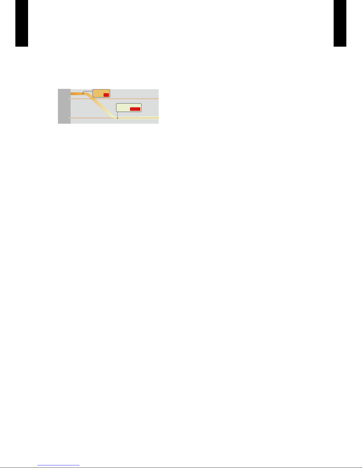
The room temperature can be set to go no lower than 10°C,
thus ensuring that the room does not get too cold when not occupied
Caution)
• When the room temperature is higher than 10°C, “10°C HEAT” operation will not start. Operation starts and maintains the room
temperature at 10°C when the temperature drops below 10°C.
• When “10°C HEAT” operation stops, the room set temperature quickly returns to the preset temperature.
10
°C
20
°C
“10°C HEAT”
Button ON
Indoor unit
operation START
Economy operation
z
The power consumption can be reduced.
Page 6
- (01 - 03) -
CEILING TYPE
AB
G18 -24 LVT
CEILING TYPE
AB
G18 -24 LVT
WIRELESS REMOTE CONTROLLER2.
FEATURES
4 mode timer setup available (ON / OFF / PROGRAM / SLEEP).
¾
Easy operation.
¾
Easy to change signal code (max. 4 units) by button operation.
¾
Simple function setting
z
Setting of the air conditioner selection function is performed by remote controller.
Built-in timers
z
Select from four different timer programs (ON / OFF / PROGRAM / SLEEP).
Program timer
z
The program timer operates the on and off timer once within a 24 hour period.
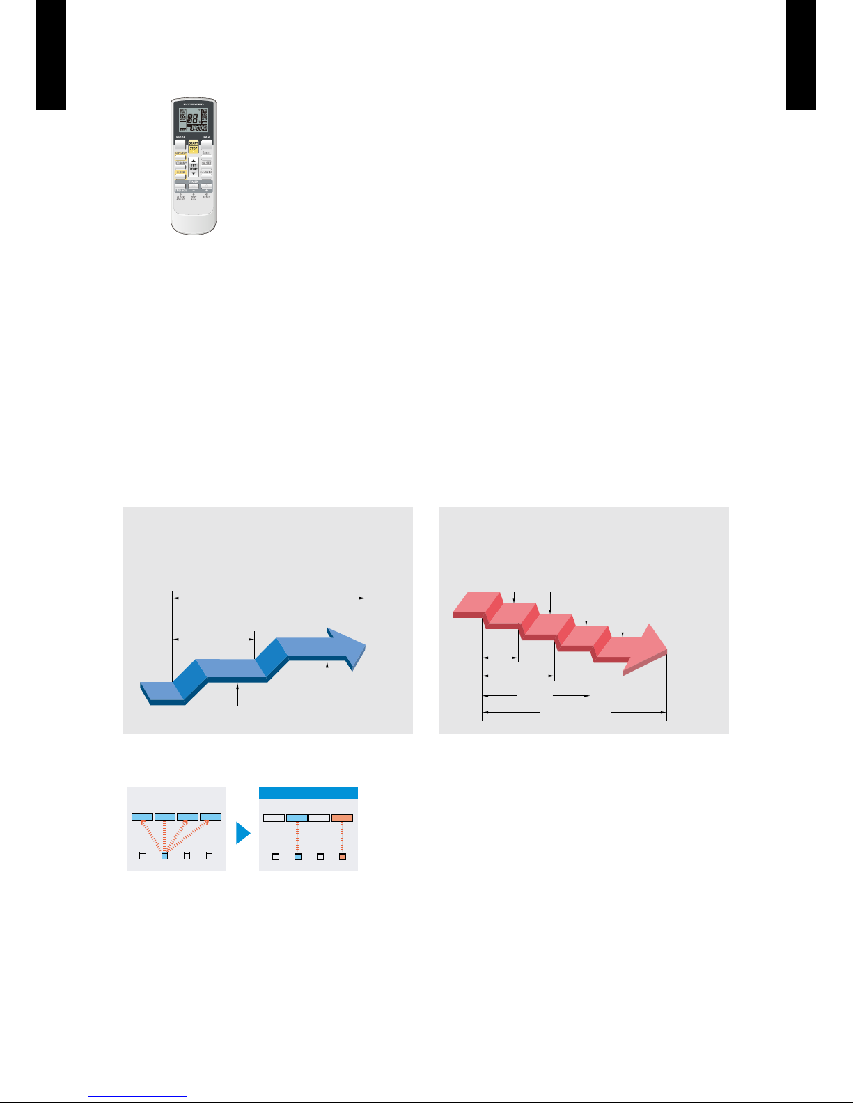
Sleep timer
z
The sleep timer function automatically corrects the temperature thermostat setting according to
the time setting to prevent excessive cooling and heating while sleeping.
Switching remote controller signal code
z
A B C D
A B
C
D
Mixed-up
I.U. I.U. I.U. I.U.
I.U. I.U. I.U. I.U.
After code change
Code selector switch eliminates unit
•
being wrongly switched.
(Up to 4 codes can be set.)
*I.U.=Indoor unit
60min.
1 °C
2 °C
Timer setting
Cooling operation/dry operation
When the sleep timer is set, the set temperature
automatically rises 1°C every hour. The set
temperature can rise up to a maximum of 2°C.
1 °C
30min.
60min.
90min.
2 °C
3 °C
4 °C
Timer setting
Heating operation
When the sleep timer is set, the set temperature
automatically drops 1°C every 30 minutes. The set
temperature can drop to a maximum of 4°C.
Page 7
- (01 - 04) -
CEILING TYPE
AB
G18 -24 LVT
CEILING TYPE
AB
G18 -24 LVT
FUNCTIONS
Note: Functions will be different due to type of indoor unit.
For details, please see operation manual.
SPECIFICATION
SIZE (H × W × D mm) 170 × 56 × 19
WEIGHT (g) 85 (w/o batteries)
ACCESSORY Holder
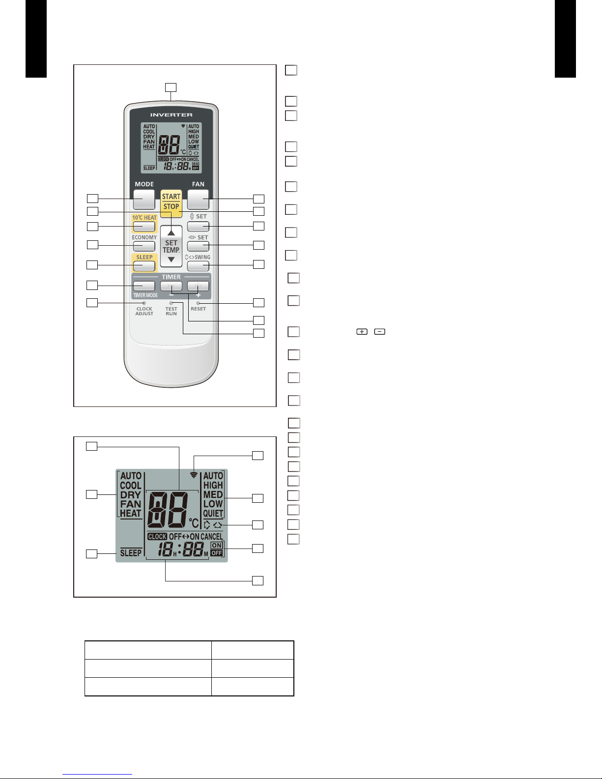
Display panel
2
4
9
3
1
16
15
5
10
13
11
12
14
8
7
6
17
18
19
21
24
23
22
20
MODE button1
Selects the operating mode (AUTO, COOL, DRY, FAN, HEAT).
/Start / end R.C. signal code change. (Max 4 types)
10°C2 HEAT button
SET TEMP. button ( ▲ / ▼ )3
Sets the indoor temp./ Sets R.C. signal code.
ECONOMY button4
SLEEP button5
Pressed to select sleep timer.
FAN button6
Selects the fan speed (AUTO, HIGH, MED, LOW, QUIET).
START/STOP button7
Pressed to start and stop operation.
SET button (Vertical)8
Air ow direction vertical set button.
SET button (Horizontal)9
Air ow direction horizontal set button.
SWING button10
Air ow direction swing button.
TIMER MODE button11
Pressed to select the timer mode. (OFF TIMER, ON TIMER,
PROGRAM TIMER, TIMER RESET)
TIMER SET ( 12
/ ) button
Sets the current time and on-off time.
CLOCK ADJUST button13
Sets the current time.
RESET button14
Used when replacing batteries.
TEST RUN button15
Used when testing the air conditioner after installation.
Signal transmitter16
Temperature set display17
Operating mode display18
Sleep display19
Transmit indicator20
Fan speed display21
Swing display22
Timer mode display23
Clock display24
Page 8
- (01 - 05) -
CEILING TYPE
AB
G18 -24 LVT
CEILING TYPE
AB
G18 -24 LVT
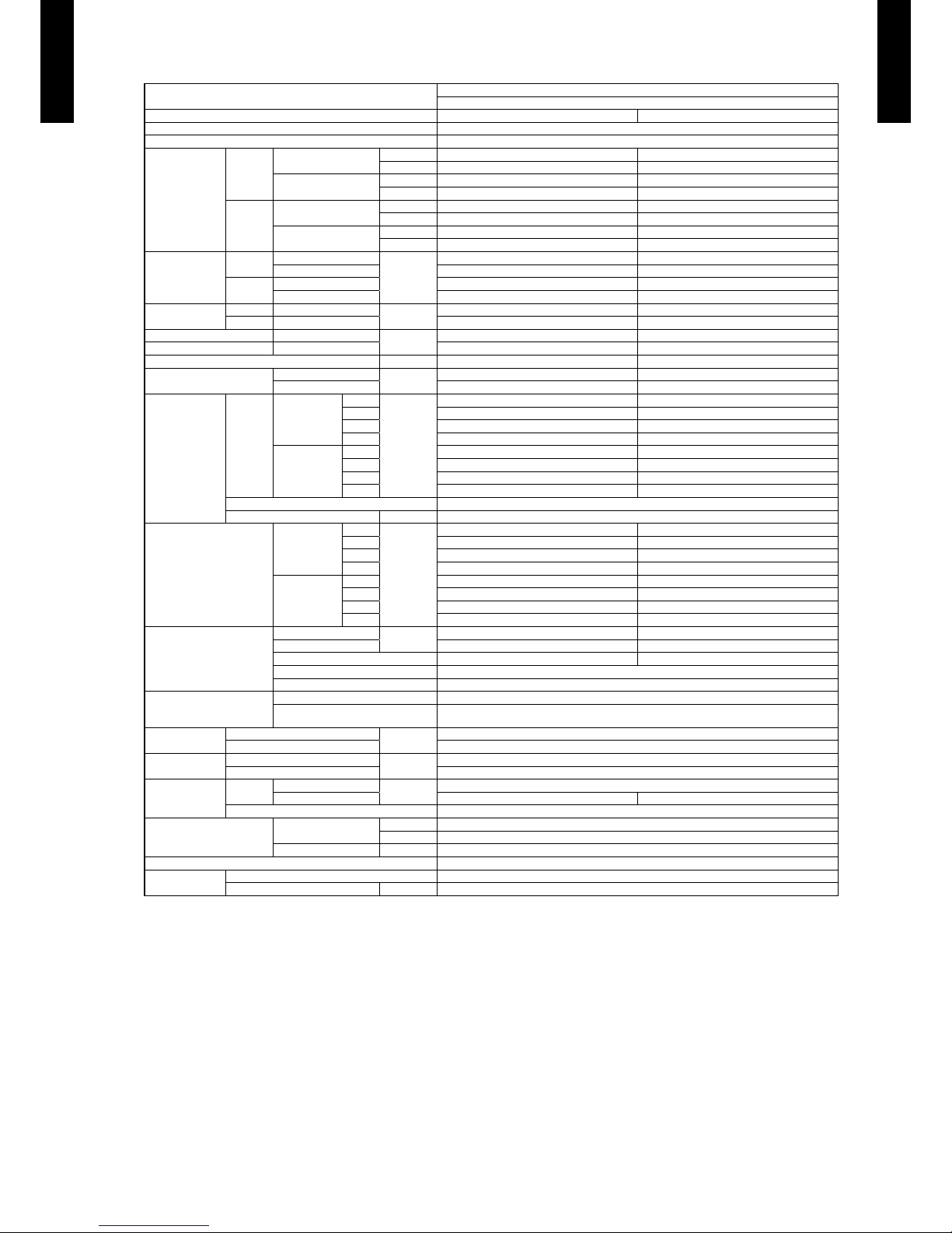
SPECIFICATIONS3.
Note :
Speci cations are base d on the foll owing conditio ns.
Coolin g : Indoor te mperat ure of 27˚CD B / 19˚CWB. and outdoor tempe rature of 3 5˚CDB / 24˚CWB .
Heating : I ndoor te mperatu re of 20˚CD B / 15˚CWB.and o utdoor te mperatu re of 7˚CD B / 6˚CWB.
Pipe leng th : 5 m, Heig ht diffe rence : 0 m. (O utdoor un it - Indoo r unit)
The prote ctive fu nction m ight work w hen using outside t he opera tion ran ge.
*: The maxi mum curr ent is the ma ximum value when op erated wi thin the o perati on range.
Type
FLOOR / CEILING MODEL
INVERTER HEATPUMP
Model name AB¾G18LVTB AB¾G24LVTA
Power source 230V
~
50Hz
Available voltage range 198 - 264V
~
50Hz
Capacity
Cooling
Rated
kW 5.20 6.80
Btu/h 17700 23200
Min - Max
kW 0.90 - 5.90 0.90 - 8.00
Btu/h 3100 - 20100 3100 - 27300
Heating
Rated
kW 6.00 8.00
Btu/h 20500 27300
Min - Max
kW 0.90 - 7.50 0.90 - 9.10
Btu/h 3100 - 25600 3100 - 31000
Input power
Cooling
Rated
kW
1.62 2.21
Max 2.04 2.85
Heating
Rated 1.66 2.26
Max 2.83 3.19
Current
Cooling Rated
A
7.2 9.7
Heating Rated 7.4 9.9
EER Cooling
kW/kW
3.21 3.08
COP Heating 3.61 3.54
Moisture removal l/h (pints/h) 2.0 (3.5) 2.9 (5.1)
Maximum operating current *
Cooling
A
9.0 12.0
Heating 12.5 13.5
Fan
Airow
rate
Cooling
High
m
3
/h
780 980
Med 700 820
Low 560 680
Quiet 500 540
Heating
High 780 980
Med 700 820
Low 560 680
Quiet 500 540
Type × Q'ty Sirocco × 2
Motor output W 80
Sound pressure level
Cooling
High
dB (A)
44 (Floor console), 43 (Under ceiling) 49 (Floor console), 48 (Under ceiling)
Med 41 (Floor console), 40 (Under ceiling) 45 (Floor console), 44 (Under ceiling)
Low 35 (Floor console), 34 (Under ceiling) 41 (Floor console), 40 (Under ceiling)
Quiet 32 (Floor console), 31 (Under ceiling) 36 (Floor console), 35 (Under ceiling)
Heating
High 44 (Floor console), 43 (Under ceiling) 49 (Floor console), 48 (Under ceiling)
Med 41 (Floor console), 40 (Under ceiling) 45 (Floor console), 44 (Under ceiling)
Low 35 (Floor console), 34 (Under ceiling) 41 (Floor console), 40 (Under ceiling)
Quiet 32 (Floor console), 31 (Under ceiling) 36 (Floor console), 35 (Under ceiling)
Heat exchanger type
Dimensions (H × W × D)
mm
252 × 800 × 39.9 252 × 800 × 53.2
Fin pitch 1.30 1.45
Rows × Stages 3 × 12 4 × 12
Pipe type Copper tube
Fin type Aluminium
Enclosure
Material ABS
Colour
WHITE
(Approximate colour of MUNSELL N9.25 /)
Dimensions
(H × W × D)
Net
mm
199 × 990 × 655
Gross 320 × 1150 × 790
Weight
Net
kg
27
Gross 36
Connection pipe
Size
Liquid
mm
Ø6.35 (Ø1/4 in.)
Gas Ø12.70 (Ø1/2 in.) Ø15.88 (Ø5/8 in.)
Method Flare
Operation range
Cooling
˚C 18 to 32
%RH 80 or less
Heating ˚C 16 to 30
Remote controller type Wireless [Wired (option)]
Drain pipe
Material Hard PVC
Size mm VP25 [Ø25 (I.D.), Ø32 (O.D.)]
Page 9

- (01 - 06) -
CEILING TYPE
AB
G18 -24 LVT
CEILING TYPE
AB
G18 -24 LVT
Model name AB
¾
G18LVTB
AB
¾
G24LVTA
Energy efciency class
Cooling A++ A+
Heating (Average) A+ A
Pdesign
Cooling
kW
5.2 (35˚C) 6.8 (35˚C)
Heating (Average) 5.2 (-10˚C) 6.0 (-10˚C)
SEER Cooling
kWh/kWh
6.10 5.60
SCOP Heating (Average) 4.00 3.90
Annual energy consumption
QCE
kWh/a
298 425
QHE (Average) 1819 2150
Sound power level
Cooling
High dB (A)
57 61
Heating 57 61
Page 10
- (01 - 07) -
CEILING TYPE
AB
G18 -24 LVT
CEILING TYPE
AB
G18 -24 LVT
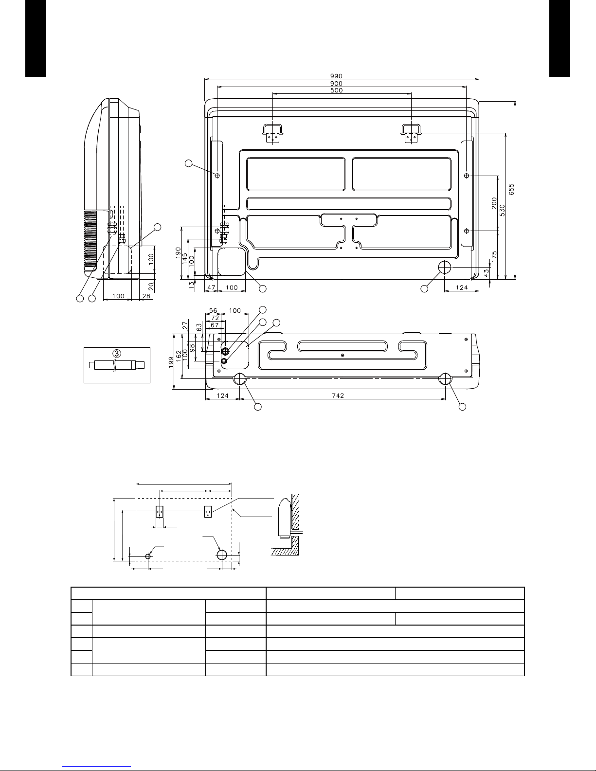
DIMENSIONS4.
MODEL : ABG18LVTB, ABG24LV TA
(Unit : mm)
1
2
4
45
6
4
12
Side view
Rear view
Bottom view
(Drain hose)
5
5
When installing set to wall install the accessory wall bracket at the position as shown in
the gure, and mount the set to it.
Wall bracket
Side of set
Unit : mm
990
500
245
ø100
100
65
65
ø50
125
530
45
655
AB¾G18LV TB AB¾G24 LVTA
Refrigerant pipe are
connection
Liquid ø 6.35 mm (ø 1/4 in.)
Gas ø 12.70 mm (ø 1/2 in.) ø 15.88 mm (ø 5/8 in.)
Drain hose connection Drain hose VP25 [Ø25 (I.D.), Ø32 (O.D.)]
Knock out hole
Drain outlet -
Pipe outlet -
Hole for lifting bolt - Use M10 screw bolt
Page 11
- (01 - 08) -
CEILING TYPE
AB
G18 -24 LVT
CEILING TYPE
AB
G18 -24 LVT
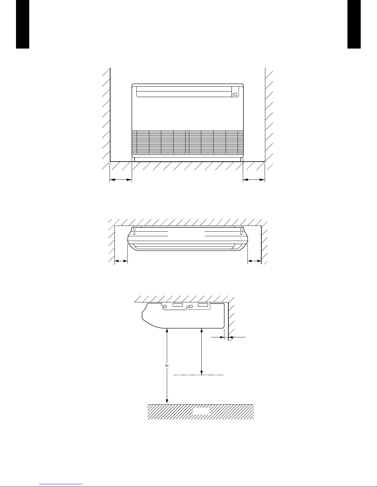
INSTALLATION PLACE
(Unit : mm)
Left Right
300 or more 300 or more
Ceiling
Left
Indoor unit
Right
150 or more 300 or more
Ceiling
20 or more
1000 or more
2300 or more
Obstruction
Floor
Floor type
z
Ceiling type
z
Page 12
- (01 - 09) -
CEILING TYPE
AB
G18 -24 LVT
CEILING TYPE
AB
G18 -24 LVT
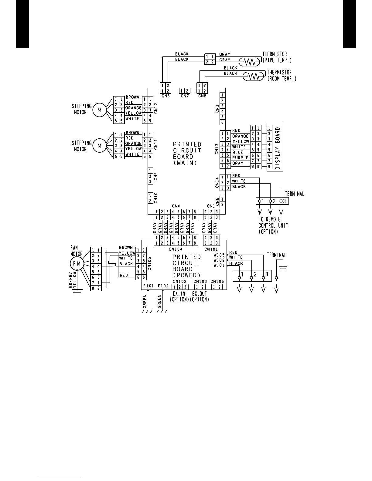
WIRING DIAGRAMS5.
MODEL : ABG18LVTB, ABG24LV TA
Page 13
- (01 - 10) -
CEILING TYPE
AB
G18 -24 LVT
CEILING TYPE
AB
G18 -24 LVT
CAPACITY TABLE6.
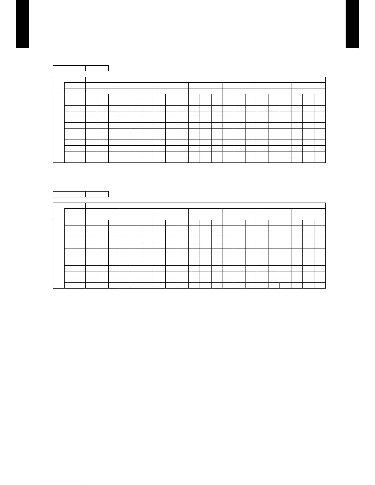
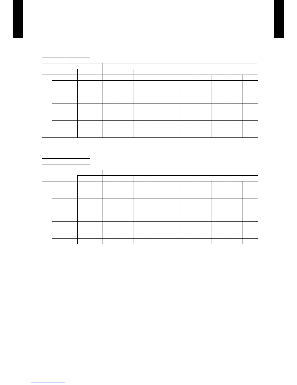
COOLING CAPACITY6-1.
This table is created using the maximum capacity.
MODEL : ABG18LVTB
MODEL : ABG24LVTA
AFR : Air Fl ow Rate (m3/min)
TC : Total Capaci ty (kW)
SHC : Sens ible Hea t Capacit y (kW)
IP : Input Pow er(kW)
AFR 13.0
Indoor temperature
°CDB 18 21 23 25 27 29 32
°CWB 12 15 16 18 19 21 23
Outdoor temperature
°CDB TC SHC IP TC SHC IP TC SHC IP TC SHC IP TC SHC IP TC SHC IP TC SHC IP
-10 4.35 3.28 0.39 4.84 3.30 0.40 5.01 3.59 0.40 5.34 3.60 0.40 5.50 3.89 0.40 5.83 3.88 0.41 6.17 4.13 0.41
0 4.26 3.24 0.46 4.74 3.26 0.46 4.90 3.54 0.47 5.23 3.56 0.47 5.39 3.84 0.47 5.71 3.83 0.48 6.04 4.07 0.48
5 4.14 3.18 0.57 4.61 3.20 0.58 4.77 3.48 0.58 5.08 3.49 0.59 5.24 3.77 0.59 5.55 3.76 0.60 5.86 4.00 0.60
10 4.00 3.12 0.68 4.45 3.14 0.69 4.61 3.41 0.70 4.91 3.42 0.70 5.06 3.70 0.71 5.37 3.68 0.71 5.67 3.92 0.72
15 4.04 3.14 0.59 4.50 3.16 0.60 4.65 3.43 0.61 4.95 3.44 0.61 5.11 3.72 0.62 5.41 3.70 0.62 5.72 3.94 0.63
20 5.16 3.63 1.28 5.75 3.65 1.30 5.95 3.97 1.31 6.34 3.98 1.32 6.54 4.30 1.33 6.93 4.28 1.34 7.32 4.56 1.35
25 4.94 3.54 1.43 5.51 3.57 1.46 5.70 3.88 1.46 6.07 3.89 1.48 6.26 4.20 1.49 6.63 4.18 1.50 7.01 4.46 1.52
30 4.71 3.45 1.59 5.25 3.47 1.61 5.43 3.78 1.62 5.78 3.79 1.64 5.96 4.09 1.65 6.32 4.07 1.66 6.68 4.34 1.68
35 4.66 3.43 1.88 5.19 3.45 1.91 5.37 3.75 1.92 5.72 3.76 1.94 5.90 4.06 1.95 6.25 4.04 1.97 6.61 4.31 1.99
40 3.53 2.90 1.34 3.93 2.92 1.36 4.06 3.18 1.36 4.33 3.19 1.38 4.46 3.44 1.38 4.73 3.43 1.40 5.00 3.65 1.41
46 2.50 2.46 1.01 2.79 2.47 1.02 2.88 2.69 1.03 3.07 2.69 1.04 3.17 2.91 1.05 3.36 2.90 1.06 3.55 3.09 1.07
AFR 15.3
Indoor temperature
°CDB 18 21 23 25 27 29 32
°CWB 12 15 16 18 19 21 23
Outdoor temperature
°CDB TC SHC IP TC SHC IP TC SHC IP TC SHC IP TC SHC IP TC SHC IP TC SHC IP
-10
5.79 4.65 0.60 6.46 4.67 0.61 6.68 5.08 0.61 7.12 5.10 0.62 7.34 5.51 0.62 7.78 5.48 0.63 8.22 5.84 0.63
0
5.69 4.59 0.64 6.34 4.62 0.65 6.55 5.02 0.65 6.98 5.04 0.66 7.20 5.44 0.66 7.63 5.42 0.67 8.06 5.77 0.68
5
5.49 4.49 0.78 6.12 4.52 0.79 6.33 4.91 0.79 6.74 4.93 0.80 6.95 5.32 0.81 7.37 5.30 0.81 7.79 5.64 0.82
10
5.28 4.38 0.91 5.88 4.40 0.92 6.08 4.79 0.93 6.48 4.80 0.94 6.68 5.19 0.94 7.08 5.17 0.95 7.48 5.50 0.96
15
5.39 4.44 0.76 6.01 4.47 0.77 6.21 4.85 0.77 6.62 4.87 0.78 6.83 5.26 0.79 7.24 5.24 0.79 7.65 5.58 0.80
20
6.85 5.22 1.61 7.63 5.25 1.64 7.89 5.71 1.64 8.41 5.73 1.66 8.67 6.18 1.67 9.19 6.16 1.69 9.71 6.56 1.70
25
6.53 5.04 1.80 7.27 5.07 1.82 7.52 5.51 1.83 8.01 5.52 1.85 8.26 5.97 1.86 8.76 5.94 1.88 9.25 6.33 1.90
30
6.18 4.86 2.00 6.89 4.88 2.03 7.12 5.31 2.04 7.59 5.33 2.06 7.83 5.75 2.07 8.30 5.73 2.09 8.77 6.10 2.11
35
6.32 4.93 2.47 7.04 4.96 2.51 7.28 5.39 2.52 7.76 5.41 2.55 8.00 5.84 2.56 8.48 5.82 2.59 8.96 6.20 2.61
40
5.21 4.34 2.05 5.81 4.37 2.08 6.01 4.75 2.09 6.40 4.77 2.11 6.60 5.15 2.12 7.00 5.13 2.14 7.39 5.46 2.16
46
3.77 3.62 1.55 4.20 3.64 1.57 4.35 3.96 1.58 4.63 3.97 1.60 4.78 4.29 1.61 5.06 4.27 1.62 5.35 4.55 1.64
Page 14
- (01 - 11) -
CEILING TYPE
AB
G18 -24 LVT
CEILING TYPE
AB
G18 -24 LVT
HEATING CAPACITY6-2.
This table is created using the maximum capacity.
MODEL : ABG18LVTB
MODEL : ABG24LV TA
AFR : Air Fl ow Rate (m3/min)
TC : Total Capaci ty (kW)
IP : Input Pow er(kW)
AFR 13.0
Indoor temperature
°CDB 16 18 20 22 24
Outdoor temperature
°CDB °CWB TC IP TC IP TC IP TC IP TC IP
-15 -16 5.25 2.15 5.13 2.20 5.00 2.24 4.88 2.29 4.75 2.33
-10 -11 5.90 2.27 5.76 2.32 5.62 2.37 5.48 2.42 5.34 2.46
-5 -7 6.57 2.40 6.41 2.45 6.26 2.50 6.10 2.55 5.94 2.60
0 -2 7.46 2.57 7.28 2.62 7.10 2.68 6.93 2.73 6.75 2.78
5 3 8.18 2.65 7.98 2.70 7.79 2.76 7.59 2.81 7.40 2.83
7 6 7.88 2.26 7.69 2.30 7.50 2.35 7.31 2.40 7.13 2.44
10 8 8.15 2.31 7.96 2.35 7.77 2.40 7.57 2.45 7.38 2.50
15 10 7.70 1.97 7.52 2.01 7.33 2.05 7.15 2.09 6.97 2.13
20 15 7.23 1.58 7.06 1.62 6.88 1.65 6.71 1.68 6.54 1.72
24 18 7.43 1.59 7.25 1.62 7.07 1.65 6.90 1.68 6.72 1.72
AFR 15.3
Indoor temperature
°CDB 16 18 20 22 24
Outdoor temperature
°CDB °CWB TC IP TC IP TC IP TC IP TC IP
-15 -16 6.15 2.70 6.00 2.76 5.86 2.82 5.71 2.87 5.57 2.93
-10 -11 6.93 2.87 6.76 2.93 6.60 2.99 6.43 3.05 6.27 3.11
-5 -7 7.64 2.86 7.46 2.91 7.28 2.97 7.10 3.03 6.92 3.09
0 -2 8.59 2.84 8.39 2.90 8.18 2.96 7.98 3.01 7.77 3.07
5 3 9.55 2.86 9.32 2.91 9.09 2.97 8.86 3.03 8.64 3.09
7 6 9.56 2.54 9.33 2.60 9.10 2.65 8.87 2.70 8.65 2.76
10 8 9.86 2.55 9.63 2.60 9.39 2.65 9.16 2.71 8.92 2.76
15 10 8.97 1.99 8.75 2.03 8.54 2.07 8.33 2.12 8.11 2.16
20 15 8.22 1.54 8.03 1.57 7.83 1.60 7.64 1.63 7.44 1.66
24 18 8.52 1.54 8.32 1.57 8.12 1.60 7.91 1.63 7.71 1.66
Page 15
- (01 - 12) -
CEILING TYPE
AB
G18 -24 LVT
CEILING TYPE
AB
G18 -24 LVT
FAN PERFORMANCE7.
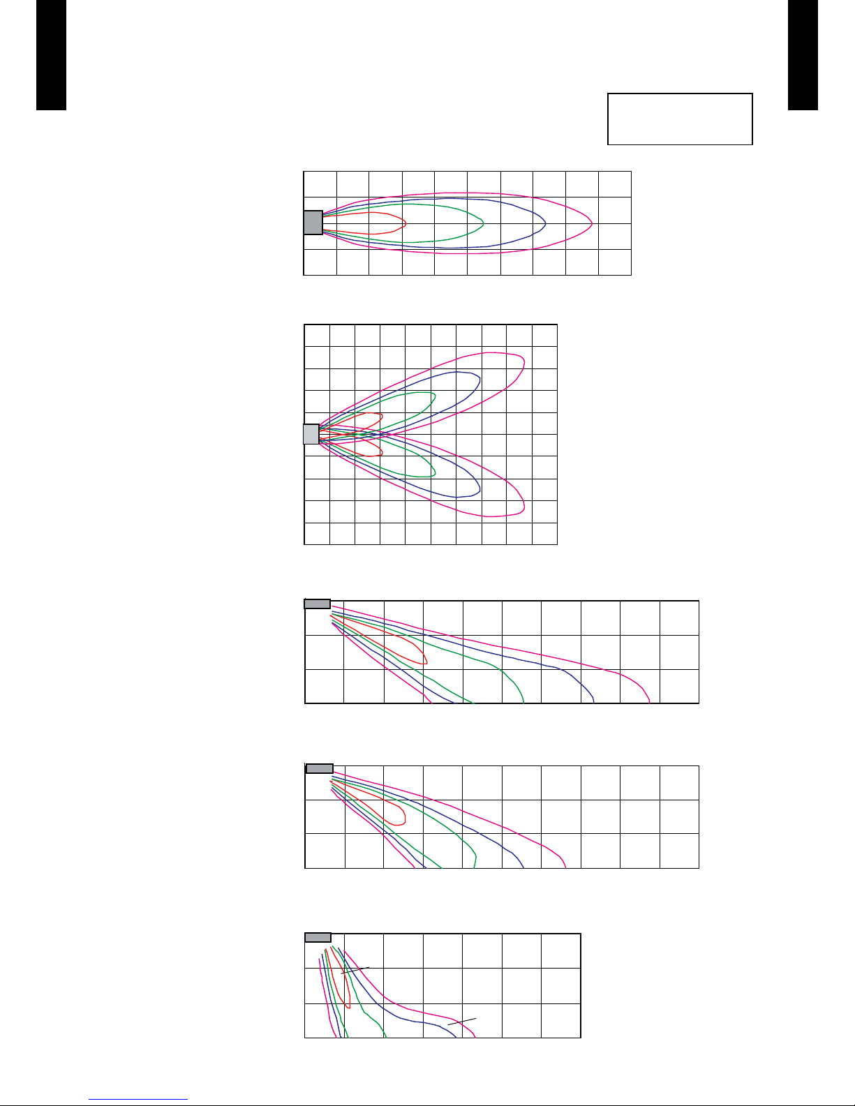
AIR VELOCITY DISTRIBUTION7-1.
MODEL : ABG18LVTB (UNDER CEILING)
Conditions
Fan speed : High
Operation mode : Fan
10
10
10
(m)
(m)
0011223344556677889
9
Unit : (m/s)
10
(m)
(m)
0
0
1
1
2
2
3
3
4
4
5
5
6
6
7
7
8 9
(m)
(m)
3
3
1
1
2
2
Top view
Vertical ap : Up
Horizontal ap : Right & Left
Unit : (m/s)
(m)
0
1
1
2
2
(m)
0 1 2 3 4 5 6 7 8 9
(m)
0
1
1
2
2
3
4
5
3
4
5
(m)
3
1
2
Unit : (m/s)
Unit : (m/s)
Unit : (m/s)
Top view
Vertical ap : Up
Horizontal ap : Center
Side view
Vertical ap : Down
Horizontal ap : Center
Side view
Vertical ap : Center
Horizontal ap : Center
Side view
Vertical ap : Up
Horizontal ap : Center
0.250.51.02.0
0.25
0.25
0.5
0.5
1.0
1.0
2.0
2.0
0.250.5
1.0
2.0
0.25
0.5
1.0
2.0
0.25
0.5
1.0
2.0
Page 16
- (01 - 13) -
CEILING TYPE
AB
G18 -24 LVT
CEILING TYPE
AB
G18 -24 LVT
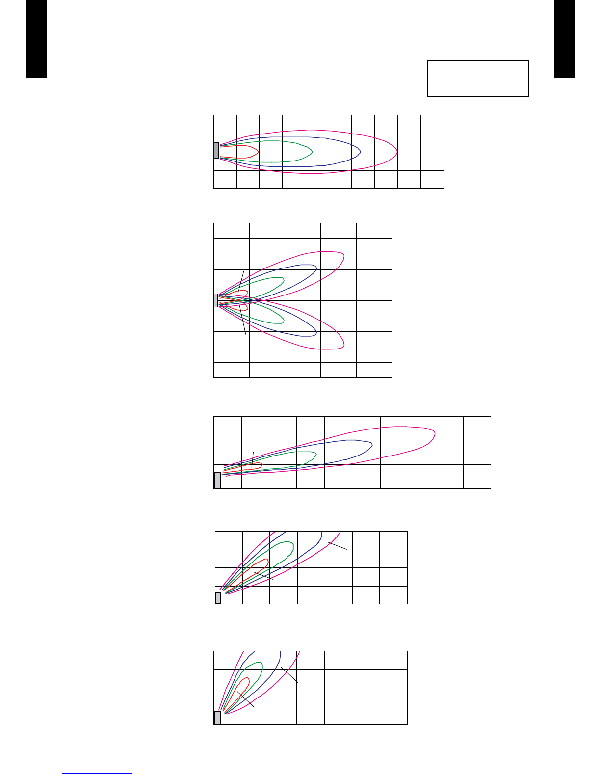
Conditions
Fan speed : High
Operation mode : Fan
MODEL : AB
¾
G18LVTB (FLOOR CONSOLE)
10
10
10
(m)
(m)
0011223344556677889
9
Unit : (m/s)
(m)
0 1 2
3
4 5 6 7
(m)
3
4
1
2
Top view
Vertical ap : Down
Horizontal ap : Right & Left
Unit : (m/s)
(m)
0
1
1
2
2
(m)
0 1 2 3 4 5 6 7 8 9
(m)
0
1
1
2
2
3
4
5
3
4
5
(m)
3
1
2
Unit : (m/s)
Unit : (m/s)
Unit : (m/s)
(m)
0 1 2
3
4 5 6 7
(m)
3
4
1
2
Top view
Vertical ap : Down
Horizontal ap : Center
Side view
Vertical ap : Up
Horizontal ap : Center
Side view
Vertical ap : Center
Horizontal ap : Center
Side view
Vertical ap : Down
Horizontal ap : Center
0.250.5
1.0
2.0
0.25
0.25
0.5
0.5
1.0
1.0
2.0
2.0
0.25
0.5
1.0
2.0
0.25
0.5
1.0
2.0
0.25
0.5
1.0
2.0
Page 17

- (01 - 14) -
CEILING TYPE
AB
G18 -24 LVT
CEILING TYPE
AB
G18 -24 LVT
Conditions
Fan speed : High
Operation mode : Fan
MODEL : AB
¾
G24LVTA (UNDER CEILING)
10
10
10
10
(m)
(m)
0
0
1
1
2
2
3
3
4
4
5
5
6
6
7
7
8
8
9
9
Unit : (m/s)
(m)
0 1 2
3
4 5 6 7
(m)
3
1
2
Top view
Vertical ap : Up
Horizontal ap : Right & Left
Unit : (m/s)
(m)
0
1
1
2
2
(m)
(m)
0011223344556677889
9
(m)
0
1
1
2
2
3
4
5
3
4
5
(m)
3
1
2
Unit : (m/s)
Unit : (m/s)
Unit : (m/s)
(m)
3
1
2
Top view
Vertical ap : Up
Horizontal ap : Center
Side view
Vertical ap : Down
Horizontal ap : Center
Side view
Vertical ap : Center
Horizontal ap : Center
Side view
Vertical ap : Up
Horizontal ap : Center
2.0 1.0
0.5
0.25
0.25
2.0
1.0
0.5
2.0
1.0
0.5
0.25
2.0
1.0
0.5
0.25
2.0
1.0
0.5
0.25
2.0
0.25
1.0
0.5
Page 18

- (01 - 15) -
CEILING TYPE
AB
G18 -24 LVT
CEILING TYPE
AB
G18 -24 LVT
2.0
1.0
0.5
0.25
Conditions
Fan speed : High
Operation mode : Fan
MODEL : AB
¾
G24LVTA (FLOOR CONSOLE)
10
10
10
(m)
(m)
0
0
1
1
2
2
3
3
4
4
5
5
6
6
7
7
8 9
Unit : (m/s)
(m)
0 1 2
3
4 5 6 7
(m)
3
1
2
Top view
Vertical ap : Down
Horizontal ap : Right & Left
Unit : (m/s)
(m)
0
1
1
2
2
(m)
(m)
0011223344556677889
9
(m)
0
1
1
2
2
3
4
5
3
4
5
(m)
3
1
2
Unit : (m/s)
Unit : (m/s)
Unit : (m/s)
(m)
3
1
2
Top view
Vertical ap : Down
Horizontal ap : Center
Side view
Vertical ap : Up
Horizontal ap : Center
Side view
Vertical ap : Center
Horizontal ap : Center
Side view
Vertical ap : Down
Horizontal ap : Center
2.0 1.0 0.5 0.25
0.25
2.0
1.0
0.5
2.0
1.0
0.5
0.25
0.25
2.0
1.0
0.5
0.25
2.0
1.0
0.5
4
4
Page 19

- (01 - 16) -
CEILING TYPE
AB
G18 -24 LVT
CEILING TYPE
AB
G18 -24 LVT
AIRFLOW7-2.
MODEL : ABG18LVTB
Cooling
z
Heating
z
Fan speed
Number of
rotations
(r.p.m.)
Airow
HIGH 1040
m
3
/h 780
l/s 217
CFM 459
MED 950
m
3
/h 700
l/s 194
CFM 412
LOW 800
m
3
/h 560
l/s 156
CFM 330
QUIET 740
m
3
/h 500
l/s 139
CFM 294
Fan speed
Number of
rotations
(r.p.m.)
Airow
HIGH 1040
m
3
/h 780
l/s 217
CFM 459
MED 950
m
3
/h 700
l/s 194
CFM 412
LOW 800
m
3
/h 560
l/s 156
CFM 330
QUIET 740
m
3
/h 500
l/s 139
CFM 294
Page 20

- (01 - 17) -
CEILING TYPE
AB
G18 -24 LVT
CEILING TYPE
AB
G18 -24 LVT
MODEL : ABG24LV TA
Cooling
z
Heating
z
Fan speed
Number of
rotations
(r.p.m.)
Airow
HIGH 1330
m
3
/h 980
l/s 272
CFM 577
MED 1150
m
3
/h 820
l/s 228
CFM 483
LOW 1000
m
3
/h 680
l/s 189
CFM 400
QUIET 780
m
3
/h 540
l/s 150
CFM 318
Fan speed
Number of
rotations
(r.p.m.)
Airow
HIGH 1300
m
3
/h 980
l/s 272
CFM 577
MED 1150
m
3
/h 820
l/s 228
CFM 483
LOW 1000
m
3
/h 680
l/s 189
CFM 400
QUIET 780
m
3
/h 540
l/s 150
CFM 318
Page 21

- (01 - 18) -
CEILING TYPE
AB
G18 -24 LVT
CEILING TYPE
AB
G18 -24 LVT
OPERATION NOISE8.
NOISE LEVEL CURVE (SOUND PRESSURE)8-1.
MODEL : ABG18LVTB
QUIET
HIGH
Heating
z
Octave ba nd sound p ressure level, dB:(0 dB= 0.00 02µbar)
Octave ba nd cente r frequ ency,Hz
80
70
60
50
40
30
20
10
0
63 125 250 500 1,000 2,000 4,00 0 8,00 0
NC-65
NC-60
NC-55
NC-50
NC-45
NC-40
NC-35
NC-30
NC-25
NC-20
NC -15
HIGH
QUIET
Heating
z
Octave ba nd sound p ressure level, dB:(0 dB= 0.00 02µbar)
Octave ba nd cente r frequ ency,Hz
80
70
60
50
40
30
20
10
0
63 125 250 500 1,000 2,000 4,00 0 8,00 0
NC-65
NC-60
NC-55
NC-50
NC-45
NC-40
NC-35
NC-30
NC-25
NC-20
NC -15
QUIET
HIGH
Cooling
z
Octave ba nd sound p ressure level, dB:(0 dB= 0.00 02µbar)
Octave ba nd cente r frequ ency,Hz
80
70
60
50
40
30
20
10
0
63 125 250 500 1,000 2,000 4,00 0 8,00 0
NC-65
NC-60
NC-55
NC-50
NC-45
NC-40
NC-35
NC-30
NC-25
NC-20
NC -15
HIGH
QUIET
Cooling
z
Octave ba nd sound p ressure level, dB:(0 dB= 0.00 02µbar)
Octave ba nd cente r frequ ency,Hz
80
70
60
50
40
30
20
10
0
63 125 250 500 1,000 2,000 4,00 0 8,00 0
NC-65
NC-60
NC-55
NC-50
NC-45
NC-40
NC-35
NC-30
NC-25
NC-20
NC -15
MODEL : ABG24LV TA
Page 22

- (01 - 19) -
CEILING TYPE
AB
G18 -24 LVT
CEILING TYPE
AB
G18 -24 LVT
SOUND LEVEL CHECK POINT8-2.
Floor console
z
Microphone
1m
Microphone
1 m
1 m
Under ceiling
z
Microphone
CEN TER
Microphone
1 m
0.8 m
Page 23

- (01 - 20) -
CEILING TYPE
AB
G18 -24 LVT
CEILING TYPE
AB
G18 -24 LVT
ELECTRIC CHARACTERISTICS9.
Model name AB¾G18LVTB AB¾G24LVTA
Power supply
Voltage V 230 ~
Frequency Hz 50
Max. operating current A 0.45 0.70
*1) Wiring Spec.
Connection cable mm
2
1.5
Limited wiring length m 26 31
*1) Wiring Spec.
Selected Sample
(Selected based on Japan Electrotechnical Standards and Codes Committee E0005)
Page 24

- (01 - 21) -
CEILING TYPE
AB
G18 -24 LVT
CEILING TYPE
AB
G18 -24 LVT
SAFETY DEVICES10.
Protection form
Model
AB¾G18LVTB
AB¾G24LVTA
Circuit protection Current fuse (PCB) 250V 3.15A
Fan motor protection
Thermal protection
program
135 ± 15 °C OFF
115 ± 15 °C ON
Page 25

- (01 - 22) -
CEILING TYPE
AB
G18 -24 LVT
CEILING TYPE
AB
G18 -24 LVT
EXTERNAL INPUT & OUTPUT11.
Connector INPUT OUTPUT REMARKS
CN102 Control input —
See external
input/output settings for
details.
CN103 — Operation status output
EXTERNAL INPUT11-1.
CONTROL INPUT (Operation/Stop or Forced stop)
The air conditioner can be remotely operated by means of the following on-site work.
"Operation/Stop" mode or "Forced stop" mode can be selected with function setting of indoor unit.
Unit operation is started at the following contents by adding the contact input of a commercial ON/OFF switch to a
connector on the external control PC board and turning it ON.
Unit operation Initial setting after power is ON Starting mode other than initial setting
Operation mode Auto changeover Mode at previous operation
Set temperature 24°C Temperature at previous operation
Air ow mode AUTO Mode at previous operation
Up-down air direction (swing) Standard air direction (swing OFF) Air direction at previous operation
Left-right air direction (swing) Standard air direction (swing OFF) Air direction at previous operation
Circuit diagram example
z
Indoor
control PC board Connected unit
Ex.) Switch
Connector
1
3
Signal
Field supply
* Make the distance from the PC board to the connected unit within 10m.
*10 m
Contact capacity : 24VDC or more, 10mA or more.
Please use non-polar relays and switches.
When function setting is in "Operation/Stop" mode ●
Operation
Stop
ON
OFF
Input signal
Indoor unit
When function setting is in "Forced stop" mode ●
Remote controller
ON ON ON
Input signal
ON
OFF
Indoor unit
Operation
Stop
Command
Forced stop
Normal
Remote control
operation invalidity
Parts (Optional)
z
Model name
UT Y-XWZ X
Wire (External input)
Page 26

- (01 - 23) -
CEILING TYPE
AB
G18 -24 LVT
CEILING TYPE
AB
G18 -24 LVT
EXTERNAL OUTPUT11-2.
OPERATION STATUS OUTPUT
An air conditioner operation status signal can be output.
Circuit diagram example
z
Field supply
Ex.)Display
Indoor
control PC board
Connected unit
Ex.)Relay unit
1
2
Signal
Relay
power
supply
V
Connector
* Make the distance from the PC board to the connected unit within 10m.
Relay spec. : Max.24VDC, 10mA to less than 1A.
*10 m
24V DC
ON
OFF
Operation
Stop
Indoor unit
Output signal
Parts (Optional)
z
Model name
UT Y-XWZ X
Wire (External output)
Page 27

- (01 - 24) -
CEILING TYPE
AB
G18 -24 LVT
CEILING TYPE
AB
G18 -24 LVT
FUNCTION SETTINGS12.
INDOOR UNIT12-1.
SWITCH POSITION
DIP-SW SETTING
Remote controller address setting
z
A number of indoor units can be operated at the same time using a wired remote controller.
Set the unit number of each indoor unit using the DIP switches on the indoor unit circuit board.
(See the following table.)
The DIP switches are normally set to make the unit number 00.
(. . .Factory setting)
Remote controller address
DIP switch No.
1 2 3 4
00 OFF OFF OFF OFF
01 ON OFF OFF OFF
02 OFF ON OFF OFF
03 ON ON OFF OFF
04 OFF OFF ON OFF
05 ON OFF ON OFF
06 OFF ON ON OFF
07 ON ON ON OFF
08 OFF OFF OFF ON
09 ON OFF OFF ON
10 OFF ON OFF ON
11 ON ON OFF ON
12 OFF OFF ON ON
13 ON OFF ON ON
14 OFF ON ON ON
15 ON ON ON ON
INDOOR UNIT
DIP SW
1
Remote controller address setting
2
3
4
Jumper Wire
JM1
Setting forbiddenJM2
JM3
JM3
JM2
JM1
1
ON
OFF
234
Indoor unit Printed circuit board
MAIN PCB
Page 28

- (01 - 25) -
CEILING TYPE
AB
G18 -24 LVT
CEILING TYPE
AB
G18 -24 LVT
INDOOR UNIT (Setting by remote controller)12-2.
The function settings of the control of the indoor unit can be changed by this procedure according •
to the installation conditions. Incorrect settings can cause the indoor unit to malfunction.
After the power is turned on, perform The Function Setting according to the installation conditions •
using the remote controller.
The settings may be selected between the following two: Function Number or Setting Value. •
Settings will not be changed if invalid numbers or setting values are selected. •
PREPARATION
Turn on the power. •
* Before turning on the power of the indoor units, make sure the piping air-tight test and vacuuming
have been conducted .
* Also check again to make sure no wiring mistakes were made before turning on the power.
FUNCTION SETTING METHOD (for Wireless remote controller)
Entering the Function Setting Mode
While pressing the FAN button and SET TEMP. (
•
) simultaneously, press the RESET button to enter the function
setting mode.
STEP 1
Setting the Remote controller Signal Code
Use the following steps to select the signal code of the remote controller. (Note that
the air conditioner cannot receive a signal code if the air conditioner has not been set
for the signal code.) The signal codes that are set through this process are applicable
only to the signals in The Function Setting. For details on how to set the signal codes
through the normal process, refer to REMOTE CONTROLLER SIGNAL CODE
SETTING.
Press the SET TEMP. (1.
) ( ) button to change the signal code between →
→
→ Match the code on the display to the air conditioner signal code. (initially
set to
)
(If the signal code does not need to be selected, press the MODE button and
proceed to STEP 2.)
Press the TIMER MODE button and check that the indoor unit can receive signals 2.
at the displayed signal code.
Press the MODE button to accept the signal code, and proceed to STEP 2.3.
The air conditioner signal code is set to A prior to shipment.
The remote controller resets to signal code A when the batteries in the remote controller are replaced. If you use a
signal code other than signal code A, reset the signal code after replacing the batteries.
If you do not know the air conditioner signal code setting, try each of the signal codes (
→ → → ) until you
nd the code which operates the air conditioner.
STEP 2
Selecting the Function Number and Setting Value
Press the SET TEMP. (1.
) ( ) buttons to select the function
numbe r.
(Press the MODE button to switch between the left and right
digits.)
Press the FAN button to proceed to setting the value. 2.
Press the FAN button again to return to the function number
selection.)
Press the SET TEMP. (3.
) ( ) buttons to select the setting value.
(Press the MODE button to switch between the left and right
digits.)
Press the TIMER MODE button, and START/STOP button, in the 4.
order listed to conrm the settings.
Press the RESET button to cancel the function setting mode.5.
After completing The Function Setting, be sure to turn off the 6.
power and turn it on again.
Function number
Setting value
CAUTION
After turning off the power, wait 10 seconds or more before turning on it again.
The Function Setting will not become active unless the power is turned off then on again.
Page 29

- (01 - 26) -
CEILING TYPE
AB
G18 -24 LVT
CEILING TYPE
AB
G18 -24 LVT
CONTENTS OF FUNCTION SETTING
Follow the instructions in the Local Setup Procedure, which is supplied with the remote control, in •
accordance with the installed condition.
After the power is turned on, perform the Function Setting on the remote control.
The settings may be selected between the following two: Function Number or Setting Value. •
Settings will not be changed if invalid numbers or setting values are selected. •
1) Filter sign
2) Ceiling height
3) Cooler room temperature correction
4) Heater room temperature correction
5) Auto restart
6) Indoor room temperature sensor switching function
7) Remote controller signal code
8) External input control
9) Indoor unit fan control for energy saving
1) Filter sign
The indoor unit has a sign to inform the user that it is time to clean the lter. Select the time setting
for the lter sign display interval in the table below according to the amount of dust or debris in the
room. If you do not wish the lter sign to be displayed, select the setting value for "No indication".
(. . .Factory setting)
Setting Description Function Number Setting Value
"Standard
(400 hours)"
11
00
"Long interval
(1,000 hours)"
01
"Short interval
(200 hours)"
02
No indication 03
2) Ceiling height
Select the setting values in the table below according to the height of the ceiling.
(. . .Factory setting)
Setting Description Function Number Setting Value
Standard
20
00
High ceiling 01
3) Cooler room temperature correction
Depending on the installed environment, the room temperature sensor may require a correction.
The settings may be selected as shown in the table below.
(. . .Factory setting)
Setting Description Function Number Setting Value
Standard
30
00
Slightly lower control 01
Lower control 02
Warmer control 03
When using oor console installation, change the setting value to "01".
Page 30

- (01 - 27) -
CEILING TYPE
AB
G18 -24 LVT
CEILING TYPE
AB
G18 -24 LVT
4) Heater room temperature correction
Depending on the installed environment, the room temperature sensor may require correction.
The settings may be changed as shown in the table below.
(. . .Factory setting)
Setting Description Function Number Setting Value
Standard
31
00
Lower control 01
Slightly warmer control 02
Warmer control 03
When using oor console installation, change the setting value to "01".
5) Auto restart
Enable or disable automatic system restart after a power outage.
(. . .Factory setting)
Setting Description Function Number Setting Value
Yes
40
00
No 01
* Auto restart is an emergency function such as for power failure etc.
Do not start and stop the indoor unit by this function in normal operation.
Be sure to operate by the control unit, or external input device.
6) Indoor room temperature sensor switching function
(Only for Wired remote controller)
The following settings are needed when use the control by Wired remote controller temperature sensor.
(. . .Factory setting)
Setting Description Function Number Setting Value
No
42
00
Yes 01
If setting value is “00”,
•
room temperature is controlled by the indoor unit temperature sensor.
If setting value is “01”,
•
room temperature is controlled by either indoor unit temperature sensor or remote controller unit sensor.
7) Remote controller signal code
Change the indoor unit Signal Code, depending on the remote controllers.
(. . .Factory setting)
Setting Description Function Number Setting Value
A
44
00
B 01
C 02
D 03
8) External input control
"Operation/Stop" mode or "Forced stop" mode can be selected.
(. . .Factory setting)
Setting Description Function Number Setting Value
Operation/Stop mode
46
00
(Setting forbidden) 01
Forced stop mode 02
9) Indoor unit fan control for energy saving (Only cooling mode)
Enable or disable indoor unit fan control when the outdoor unit is stopped.
(. . .Factory setting)
Setting Description Function Number Setting Value
No
49
00
Yes 01
If setting value is “00”,
•
When the outdoor unit is stopped, the indoor unit fan operates following the setting on the remote controller continuously.
If setting value is “01”,
•
When the outdoor unit is stopped, the indoor unit fan operates at very low speed intermittently.
Page 31

- (01 - 28) -
CEILING TYPE
AB
G18 -24 LVT
CEILING TYPE
AB
G18 -24 LVT
REMOTE CONTROLLER SIGNAL CODE SETTING
Use the following steps to select the signal code of the remote controller.
(Note that the air conditioner cannot receive a signal code if the air conditioner has not been set for the signal code.)
1. Press the START/STOP button until only the clock is displayed on the remote controller display.
2. Press the MODE button for at least ve seconds to display the current signal code (initially set to
).
3. Press the SET TEMP. ( ) ( ) button to change the signal code between → → → .
Match the code on the display to the air conditioner signal code.
4. Press the MODE button again to return to the clock display. The signal code will be changed.
If no buttons are pressed within 30 seconds after the signal code is displayed, the system returns to the original clock
display. In this case, start again from step 1.
The air conditioner signal code is set to A prior to shipment. Contact your retailer to change the signal code.
The remote controller resets to signal code A when the batteries in the remote controller are replaced. If you use a
signal code other than signal code A, reset the signal code after replacing the batteries.
If you do not know the air conditioner signal code setting,try each of the signal codes (
→ → → .) until you
nd the code which operates the air conditioner.
Page 32

- (01 - 29) -
CEILING TYPE
AB
G18 -24 LVT
CEILING TYPE
AB
G18 -24 LVT
OPTIONAL PARTS13.
CONTROLLER13-1.
Exterior Parts name Model No. Summary
Wired remote
controller
UTY-RVN¾M
Large and full-dot liquid
crystal screen, wide and
large keys easy to press,
user-intuitive arrow key.
Wired remote
controller
UTY-RNN¾M
The room temperature can
be controlled by detecting the
temperature accurately with
built-in thermo sensor.
Simple remote
controller
UTY-RSN¾M
Compact remote controller
concentrates on the basic
functions such as Start/Stop,
Fan Control, Temperature
Setting and Operation mode.
OTHERS13-2.
Exterior Parts name Model No. Summary
External
connect kit
UTY-XWZX
Use to connect with various
peripheral devices and air
conditioner PC board.
Page 33

2. OUTDOOR UNIT
SINGLE TYPE :
AOG12LALL
AOG14LALL
AOG18LALL
AOG24LALA
DTR_AO099E_02
2013.02.28
Page 34

OUTDOOR UNIT
AO
G12-24LAL
OUTDOOR UNIT
AO
G12-24LAL
CONTENTS
2. OUTDOOR UNIT
1. SPECIFICATIONS
.............................................................................................. 02 - 01
2. DIMENSIONS
........................................................................................................ 02 - 02
3. REFRIGERANT CIRCUIT
............................................................................ 02 - 03
4. WIRING DIAGRAMS
........................................................................................ 02 - 04
5. CAPACITY COMPENSATION RATE FOR PIPE LENGTH
AND HEIGHT DIFFERENCE
..................................................................... 02 - 06
6. ADDITIONAL CHARGE CALCULATION
......................................... 02 - 10
7. AIRFLOW
..................................................................................................................02 - 11
8. OPERATION NOISE (SOUND PRESSURE)
................................. 02 - 13
8-1. NOISE LEVEL CURVE
...................................................................................... 02 - 13
8-2. SOUND LEVEL CHECK POINT
...................................................................... 02 - 15
9. ELECTRIC CHARACTERISTICS
........................................................... 02 - 16
10. SAFETY DEVICES
............................................................................................ 02 - 17
Page 35

- (02 - 01) -
OUTDOOR UNIT
AO
G12-24LAL
OUTDOOR UNIT
AO
G12-24LAL
SPECIFICATIONS1.
Typ e INVERTER HEAT PUMP
Model name AOG12L AL L AOG14L ALL AOG18LALL AOG24LALA
Power sourc e 230V ~ 50Hz
Available voltage range 198 - 264V ~ 50Hz
Starting current A 5 .1 6 .1 7. 4 9.9
Fan
Airow rate
Cooling
m
3
/h
1780 1910 2000 2470
Heating 1630 174 0 1910 2470
Type × Q'ty Propeller × 1
Motor output W 54 65
Sound pressure level
Cooling
dB (A)
47 49 50 52
Heating 48 49 50 53
Sound power level
Cooling
dB (A)
61 62 62 67
Heating 63 64 65 70
Heat exchanger type
Dimensions
(H × W × D)
mm
546 × 876 × 18.2
546 × 842 × 18.2
546 × 86 6 × 18.2
546 × 832 × 18.2
504 × 58 9 × 18.2
Fin pitch 1.30 1.40
Rows × Stages 2 × 26
2 × 26
1 × 24
Pipe type Copper
Fin Type Aluminium
Compressor
Type × Q'ty Twin Rotary × 1
Motor output W 11 00
Refrigerant
Typ e
(Global Warming Potent ial)
R410 A(197 5)
Charge g 1150 1250 1700
Refrigerant oil Type POE
Enclosure
Material Steel sheet
Colour
Beige
Approximate colour of MUNSELL 10YR7.5/1.0
Dimensions
(H × W × D)
Net
mm
578 × 790 ×300 578 × 79 0 ×315
Gross 648 × 910 × 38 0
Weight
Net
kg
40 44
Gross 44 48
Connenction pipe
Size
Liquid
mm
Ø6.35 (Ø1/4 in.)
Gas Ø9.52 (Ø3/8 in.) Ø12.70 (Ø1/2 in.) Ø15.88 (Ø5/8 in.)
Method Flare
Pre-charge length
m
15
Max. length 25 30
Max. hei ght difference 15 20
Operation range
Cooling
°C
-10 to 46
Heating -15 to 24
Note :
Specications are based on the following conditions.
Cooling : Indoor temperature of 27 °CDB / 19 °CWB.and outdoor temperature of 35 °CDB / 24 °CWB.
Heating : Indoor temperature of 20 °CDB / 15 °CW B.and outdoor temperature of 7 °CDB / 6 °CW B.
Pipe length : 5.0 m, Height difference : 0 m. (Outdoor unit - Indoor unit)
The protective function may work when using it out side the operation range.
Page 36

- (02 - 02) -
OUTDOOR UNIT
AO
G12-24LAL
OUTDOOR UNIT
AO
G12-24LAL
DIMENSIONS2.
MODEL : AOG12LALL, AOG14LALL, AOG18LALL, AOG24LALA
(Unit : mm)
INSTALLATION PLACE
600 mm
or more
100 mm
or more
600 mm or more
300 mm
or more
100 mm
or more
300 mm or more
(Service space)
300 mm
or more
300 mm
or more
300 mm
or more
When there are obstacles at
the back or front sides.
When there are obstacles at
the back, side(s), and top.
When there are obstacles at the
back, side with the installation of
more than one unit.
Air flow
Top view
Front view
Side view
Bottom view
AO G24LALAAO G12LALL
AO G14LALL
AO G18LALL
Page 37

- (02 - 03) -
OUTDOOR UNIT
AO
G12-24LAL
OUTDOOR UNIT
AO
G12-24LAL
REFRIGERANT CIRCUIT3.
MODEL : AOG12LALL, AOG14LALL, AOG18LALL, AOG24LALA
Refrigerant pipe diameter
Liquid : 1/4" (6.35 mm)
Gas : 3/8" (9.52 mm) : AO*G12LALL
1/2" (12.70 mm) : AO*G14LALL, AO*G18LALL
5/8" (15.88 mm) : AO*G24LALA
Page 38

- (02 - 04) -
OUTDOOR UNIT
AO
G12-24LAL
OUTDOOR UNIT
AO
G12-24LAL
WIRING DIAGRAMS4.
MODEL : AOG12LALL, AOG14LALL, AOG18LALL
Page 39

- (02 - 05) -
OUTDOOR UNIT
AO
G12-24LAL
OUTDOOR UNIT
AO
G12-24LAL
MODEL : AOG24LALA
Page 40

- (02 - 06) -
OUTDOOR UNIT
AO
G12-24LAL
OUTDOOR UNIT
AO
G12-24LAL
CAPACITY COMPENSATION RATE FOR PIPE LENGTH 5.
AND HEIGHT DIFFERENCE
This table is created using the maximum capacity.
MODEL : AOG12LALL
HEATING
Pipe length (m)
5 7. 5 10 15 20 25
Height
difference H
(m)
Û
1
Indoor unit is
higher than
outdoor unit.
15 - - - 0.943 0.916 0.896
10 - - 1.010 0.943 0.916 0.896
7. 5 - 1.000 1.010 0.943 0.916 0.896
5 1.000 1.000 1.010 0.943 0.916 0.896
0 1.000 1.000 1.010 0.943 0.916 0.896
Û
2
Indoor unit is
lower than
outdoor unit.
-5 0.995 0.995 1.00 5 0.939 0. 912 0.892
-7. 5 - 0.993 1.0 02 0.936 0.909 0.890
-10 - - 0.999 0.934 0.907 0.887
-15 - - - 0.925 0.898 0.878
COOLING
Pipe length (m)
5 7. 5 10 15 20 25
Height
difference H
(m)
Û
1
Indoor unit is
higher than
outdoor unit.
15 - - - 0.903 0.894 0.867
10 - - 0.964 0.918 0.909 0.881
7. 5 - 0.988 0.968 0.922 0.912 0.885
5 0.992 0.992 0.972 0.925 0.916 0.888
0 1.000 1.000 0.980 0.933 0.923 0.895
Û
2
Indoor unit is
lower than
outdoor unit.
-5 1.000 1.000 0.980 0.933 0.923 0.895
-7. 5 - 1.000 0.980 0.933 0.923 0.895
-10 - - 0.980 0.933 0.923 0.895
-15 - - - 0.933 0.923 0.895
Height difference H
1 Indoor unit is higher than outdoor unit.
2 Indoor unit is lower than outdoor unit.
Indoor unit
Indoor unit
Connection pipe
Outdoor unit
Outdoor unit
Connection pipe
H H
Page 41

- (02 - 07) -
OUTDOOR UNIT
AO
G12-24LAL
OUTDOOR UNIT
AO
G12-24LAL
This table is created using the maximum capacity.
MODEL : AOG14LALL
Height difference H
1 Indoor unit is higher than outdoor unit.
2 Indoor unit is lower than outdoor unit.
Indoor unit
Indoor unit
Connection pipe
Outdoor unit
Outdoor unit
Connection pipe
HEATING
Pipe length (m)
5 7. 5 10 15 20 25
Height
difference H
(m)
Û
1
Indoor unit is
higher than
outdoor unit.
15 - - - 0.918 0.891 0.862
10 - - 0.981 0.918 0.891 0.862
7. 5 - 1.000 0.981 0.918 0.891 0.862
5 1.000 1.000 0.981 0.918 0.891 0.862
0 1.000 1.000 0.981 0.918 0.891 0.862
Û
2
Indoor unit is
lower than
outdoor unit.
-5 0.995 0.995 0.976 0.914 0.886 0.858
-7. 5 - 0.993 0.974 0.912 0.884 0.856
-10 - - 0.972 0.909 0.882 0.854
-15 - - - 0.900 0.873 0.845
COOLING
Pipe length (m)
5 7. 5 10 15 20 25
Height
difference H
(m)
Û
1
Indoor unit is
higher than
outdoor unit.
15 - - - 0.953 0.950 0.9 47
10 - - 0.983 0.968 0.966 0.962
7. 5 - 0.988 0.987 0.972 0.970 0.966
5 0.992 0.992 0.991 0.976 0.9 74 0.970
0 1.000 1.000 0.999 0.984 0.982 0.978
Û
2
Indoor unit is
lower than
outdoor unit.
-5 1.000 1.000 0.999 0.984 0.982 0.978
-7. 5 - 1.000 0.999 0.984 0.982 0.978
-10 - - 0.999 0.984 0.982 0.978
-15 - - - 0.984 0.982 0.978
H H
Page 42

- (02 - 08) -
OUTDOOR UNIT
AO
G12-24LAL
OUTDOOR UNIT
AO
G12-24LAL
This table is created using the maximum capacity.
MODEL : AOG18LALL
Height difference H
1 Indoor unit is higher than outdoor unit.
2 Indoor unit is lower than outdoor unit.
Indoor unit
Indoor unit
Connection pipe
Outdoor unit
Outdoor unit
Connection pipe
HEATING
Pipe length (m)
5 7. 5 10 15 20 25
Height
difference H
(m)
Û
1
Indoor unit is
higher than
outdoor unit.
15 - - - 0.920 0.894 0.867
10 - - 0.982 0.920 0.894 0.867
7. 5 - 1.000 0.982 0.920 0.894 0.867
5 1.000 1.000 0.982 0.920 0.894 0.867
0 1.000 1.000 0.982 0.920 0.894 0.867
Û
2
Indoor unit is
lower than
outdoor unit.
-5 0.995 0.995 0.977 0.916 0.889 0.862
-7. 5 - 0.993 0.975 0.913 0.887 0.860
-10 - - 0.972 0 .911 0.885 0.858
-15 - - - 0.902 0.876 0.849
COOLING
Pipe length (m)
5 7. 5 10 15 20 25
Height
difference H
(m)
Û
1
Indoor unit is
higher than
outdoor unit.
15 - - - 0.953 0.950 0.9 47
10 - - 0.983 0.968 0.966 0.962
7. 5 - 0.988 0.987 0.972 0.970 0.966
5 0.992 0.992 0.991 0.976 0.9 74 0.970
0 1.000 1.000 0.999 0.984 0.982 0.978
Û
2
Indoor unit is
lower than
outdoor unit.
-5 1.000 1.000 0.999 0.984 0.982 0.978
-7. 5 - 1.000 0.999 0.984 0.982 0.978
-10 - - 0.999 0.984 0.982 0.978
-15 - - - 0.984 0.982 0.978
H H
Page 43

- (02 - 09) -
OUTDOOR UNIT
AO
G12-24LAL
OUTDOOR UNIT
AO
G12-24LAL
This table is created using the maximum capacity.
MODEL : AOG24LALA
Height difference H
1 Indoor unit is higher than outdoor unit.
2 Indoor unit is lower than outdoor unit.
Indoor unit
Indoor unit
Connection pipe
Outdoor unit
Outdoor unit
Connection pipe
HEATING
Pipe length (m)
5 7. 5 10 15 20 25 30
Height
difference H
(m)
Û
1
Indoor unit is
higher than
outdoor unit.
20 - - - - 0.927 0.893 0.863
10 - - 0.992 0.952 0.927 0.893 0.863
7. 5 - 1.000 0.992 0.952 0.927 0.893 0.863
5 1.000 1.000 0.992 0.952 0.927 0.893 0.863
0 1.000 1.000 0.992 0.952 0.927 0.893 0.863
Û
2
Indoor unit is
lower than
outdoor unit.
-5 0.995 0.995 0.987 0.9 47 0.922 0.888 0.859
-7. 5 - 0.993 0.984 0.945 0.920 0.886 0.857
-10 - - 0.982 0.943 0.917 0.884 0.855
-20 - - - - 0.908 0.875 0.846
COOLING
Pipe length (m)
5 7. 5 10 15 20 25 30
Height
difference H
(m)
Û
1
Indoor unit is
higher than
outdoor unit.
20 - - - - 0.963 0.961 0.959
10 - - 0.984 0.981 0.979 0.977 0.975
7. 5 - 0.988 0.988 0.985 0.983 0.981 0.979
5 0.992 0.992 0.992 0.989 0.987 0.985 0.983
0 1.000 1.000 1.000 0.997 0.995 0.993 0.991
Û
2
Indoor unit is
lower than
outdoor unit.
-5 1.000 1.000 1.000 0.997 0.995 0.993 0.991
-7. 5 - 1.000 1.000 0.997 0.995 0.993 0.991
-10 - - 1.000 0.997 0.995 0.993 0.991
-20 - - - - 0.995 0.993 0.991
H H
Page 44

- (02 - 10) -
OUTDOOR UNIT
AO
G12-24LAL
OUTDOOR UNIT
AO
G12-24LAL
ADDITIONAL CHARGE CALCULATION6.
MODEL : AOG12LALL
Refrigerant charge
z
MODEL : AOG14LALL, AOG18LALL
Refrigerant charge
z
MODEL : AOG24LALA
Refrigerant charge
z
Refrigerant type R410 A
Refrigerant amount g 1150
Total pipe length m 15 or less 20 25 (MAX)
20g/m
Additional charge g 0 10 0 200
Refrigerant type R410 A
Refrigerant amount g 1250
Total pipe length m 15 or less 20 25 (MAX)
20g/m
Additional charge g 0 10 0 200
Refrigerant type R410 A
Refrigerant amount g 1700
Total pipe length m 15 or less 20 25 30 (MA X)
20g/m
Additional charge g 0 10 0 200 300
Page 45

- (02 - 11) -
OUTDOOR UNIT
AO
G12-24LAL
OUTDOOR UNIT
AO
G12-24LAL
AIRFLOW7.
MODEL : AOG12LALL
Cooling
z
Heating
z
MODEL : AOG14LALL
Cooling
z
Heating
z
Number of
rotations
(r.p.m.)
Airow
770
m
3
/h 1780
l/s 494
CFM 1048
Number of
rotations
(r.p.m.)
Airow
700
m
3
/h 1630
l/s 453
CFM 959
Number of
rotations
(r.p.m.)
Airow
820
m
3
/h 1910
l/s 531
CFM 112 4
Number of
rotations
(r.p.m.)
Airow
750
m
3
/h 1740
l/s 483
CFM 1024
Page 46

- (02 - 12) -
OUTDOOR UNIT
AO
G12-24LAL
OUTDOOR UNIT
AO
G12-24LAL
MODEL : AOG18LALL
Cooling
z
Heating
z
MODEL : AOG24LALA
Cooling
z
Heating
z
Number of
rotations
(r.p.m.)
Airow
860
m
3
/h 2000
l/s 556
CFM 117 7
Number of
rotations
(r.p.m.)
Airow
820
m
3
/h 1910
l/s 531
CFM 112 4
Number of
rotations
(r.p.m.)
Airow
1050
m
3
/h 2470
l/s 686
CFM 1454
Number of
rotations
(r.p.m.)
Airow
1050
m
3
/h 2470
l/s 686
CFM 1454
Page 47

- (02 - 13) -
OUTDOOR UNIT
AO
G12-24LAL
OUTDOOR UNIT
AO
G12-24LAL
OPERATION NOISE (SOUND PRESSURE)8.
NOISE LEVEL CURVE8-1.
MODEL : AOG12LALL
Cooling
z
Octave ba nd sound p ressure level, dB:(0 dB= 0.00 02µbar)
Octave ba nd cente r frequ ency,Hz
80
70
60
50
40
30
20
10
0
63 125 250 500 1,000 2,000 4,00 0 8,00 0
NC-65
NC-60
NC-55
NC-50
NC-45
NC-40
NC-35
NC-30
NC-25
NC-20
NC -15
Heating
z
Octave ba nd sound p ressure level, dB:(0 dB= 0.00 02µbar)
Octave ba nd cente r frequ ency,Hz
80
70
60
50
40
30
20
10
0
63 125 250 500 1,000 2,000 4,00 0 8,00 0
NC-65
NC-60
NC-55
NC-50
NC-45
NC-40
NC-35
NC-30
NC-25
NC-20
NC -15
Heating
z
Octave ba nd sound p ressure level, dB:(0 dB= 0.00 02µbar)
Octave ba nd cente r frequ ency,Hz
80
70
60
50
40
30
20
10
0
63 125 250 500 1,000 2,000 4,00 0 8,00 0
NC-65
NC-60
NC-55
NC-50
NC-45
NC-40
NC-35
NC-30
NC-25
NC-20
NC -15
Octave ba nd sound p ressure level, dB:(0 dB= 0.00 02µbar)
Octave ba nd cente r frequ ency,Hz
80
70
60
50
40
30
20
10
0
63 125 250 500 1,000 2,000 4,00 0 8,00 0
MODEL : AOG14LALL
Cooling
z
NC-65
NC-60
NC-55
NC-50
NC-45
NC-40
NC-35
NC-30
NC-25
NC-20
NC -15
Page 48

- (02 - 14) -
OUTDOOR UNIT
AO
G12-24LAL
OUTDOOR UNIT
AO
G12-24LAL
MODEL : AOG18LALL
Cooling
z
Octave ba nd sound p ressure level, dB:(0 dB= 0.00 02µbar)
Octave ba nd cente r frequ ency,Hz
80
70
60
50
40
30
20
10
0
63 125 250 500 1,000 2,000 4,00 0 8,00 0
NC-65
NC-60
NC-55
NC-50
NC-45
NC-40
NC-35
NC-30
NC-25
NC-20
NC -15
Heating
z
Octave ba nd sound p ressure level, dB:(0 dB= 0.00 02µbar)
Octave ba nd cente r frequ ency,Hz
80
70
60
50
40
30
20
10
0
63 125 250 500 1,000 2,000 4,00 0 8,00 0
NC-65
NC-60
NC-55
NC-50
NC-45
NC-40
NC-35
NC-30
NC-25
NC-20
NC -15
Heating
z
Octave ba nd sound p ressure level, dB:(0 dB= 0.00 02µbar)
Octave ba nd cente r frequ ency,Hz
80
70
60
50
40
30
20
10
0
63 125 250 500 1,000 2,000 4,00 0 8,00 0
NC-65
NC-60
NC-55
NC-50
NC-45
NC-40
NC-35
NC-30
NC-25
NC-20
NC -15
Octave ba nd sound p ressure level, dB:(0 dB= 0.00 02µbar)
Octave ba nd cente r frequ ency,Hz
80
70
60
50
40
30
20
10
0
63 125 250 500 1,000 2,000 4,00 0 8,00 0
MODEL : AOG24LALA
Cooling
z
NC-65
NC-60
NC-55
NC-50
NC-45
NC-40
NC-35
NC-30
NC-25
NC-20
NC -15
Page 49

- (02 - 15) -
OUTDOOR UNIT
AO
G12-24LAL
OUTDOOR UNIT
AO
G12-24LAL
SOUND LEVEL CHECK POINT8-2.
Airflow
Page 50

- (02 - 16) -
OUTDOOR UNIT
AO
G12-24LAL
OUTDOOR UNIT
AO
G12-24LAL
ELECTRIC CHARACTERISTICS9.
Model name AOG12L A LL AOG14L ALL AOG18L ALL AOG24LALA
Power supply
Voltage V 230 ~
Frequency Hz 50
*1) Max operating current A 10.0 12.5 13 .5
Starting Current A 5 .1 6 .1 7. 4 9.9
*2) Wiring Spec.:
Main Fuse (Circuit breaker)
Current
A 25
Power Cable mm
2
4.0
*1) The maximum current is the total current of indoor unit and outdoor unit.
*2) Wiring Spec.:
Selected Sample
(Selected based on Japan Electrotechnical Standards and Codes Committee E0005)
Page 51

- (02 - 17) -
OUTDOOR UNIT
AO
G12-24LAL
OUTDOOR UNIT
AO
G12-24LAL
SAFETY DEVICES10.
Protection form
Model
AOG12L A LL AOG14L ALL AOG18L ALL AOG24LALA
Circuit protection
Current fuse
(Near the terminal)
250V 20A
250V 5A
Current fuse
(Main printed
circuit board)
250V 15A
250V 3.15A
Fan motor
protection
Thermal protection
program
OFF : 100
+15
-10
°C
ON : 95
+15
-10
°C
OFF : 110
+15
-10
°C
ON : 105
+15
-10
°C
Compressor
protection
Terminal protection program
(Compressor temp.)
OFF : 110°C
ON : After 40 minutes and 80°C or less
Thermal protection program
(Discharge temp.)
OFF : 110°C
ON : After 7 minutes
 Loading...