

Page 1

Fujitsu LifeBook
A Series
BIOS Guide
LifeBook A Series Model:
A1010
Document Date: 05/20/02
Document Part Number: FPC58-0681-01
FUJITSU PC CORPORATION
1
Page 2

LifeBook A Series Notebook BIOS
A Series BIOS
SYSTEM CONFIGURATION UTILITY (SCU)
The BIOS System Configuration Utility (SCU) is a
program that sets up the operating environment for
your notebook. Your BIOS is set at the factory for
normal operating conditions, therefore there is no need
to set or change the BIOS environment to operate your
notebook.
The SCU configures:
■
Device control feature parameters, such as changing
I/O addresses and boot devices.
■
System Data Security feature parameters, such
as passwords.
Entering the System Configuration Utility
To enter the BIOS SCU, do the following:
1. Turn on or restart your notebook.
2. Press the [F2] key once the Fujitsu logo appears on
the screen. Note that this occurs almost immediately
when the system boots up, so have your finger on the
F2 button when the boot starts. Pressing F2 opens
the main menu of the SCU with the current settings
displayed.
3. Press the [Enter] key to enable the dropdown
menus, then press the right arrow or left arrow
cursor key to scroll through the other setup menus
to review or alter the current settings.
Navigating Through the SCU
The BIOS SCU consists of five dropdown menus:
Startup, Memory, Disks, Components, and Exit. This
document explains each menu in turn, including all
submenus and setup items.
The following procedures allow you to navigate the
utility menus:
1. To select a menu, use the left and right cursor keys:
[ ], [ ]
2. To select a field within a menu or a submenu, use the
up and down cursor keys:
[ ], [ ].
3. This automatically selects the field upon which the
prompt rests. Click OK to select the choice, or
Cancel to exit the screen without making the
change.
4. To activate a submenu press the [Enter] key.
5. To return to a menu from a submenu, press the
[Esc] key.
6. To go to the Exit menu from any other menu, press
the [Esc] key.
POINT
Selecting a field or submenu causes a help message
about that field to be displayed on the bottom of the
screen.
Entering the SCU After a Configuration Change or System Failure
Each time the system boots, the BIOS performs diagnostic testing of the various system components. During
a standard implementation, if the BIOS detects an error,
one of the following events occurs:
■
A message with the prefix “WARNING” is displayed
informing the user where the error occurred. Following the message, the prompt “Press F1 to continue” is
displayed. The system pauses until the user presses F1.
■
A message with the prefix “FATAL” is displayed
informing the user where the error occurred. Following the message, the system emits a series of beeps. The
system then halts execution.
■
The system emits a series of beeps. The system then
halts execution.
Warning messages are considered “non-fatal” errors,
indicating that a potential problem exists such as a
system configuration error. When F1 is pressed, the
system should resume execution. Non-fatal errors can be
corrected by the user.
Fatal errors (those that emit a beep and may also display
a “FATAL” message) indicate that the BIODS has
stopped the system from continuing operation due to a
severe problem such as a hardware failure. Fatal errors
do not allow the system to resume execution. All fatal
errors generate a series of beeps whether a message is
displayed or not. See “Beep Codes” in the Troubleshooting section of your system User’s Guide for more
information.
2
Page 3

The troubleshooting section of the system User’s Guide
lists the messages that may appear while using the BIOS.
Where applicable, possible solutions are included. Each
fatal error message also includes the corresponding beep
code
If there has been a change in the system configuration
that does not agree with the parameter settings stored
in your BIOS memory, or there is a failure in the system,
the system beeps and/or displays an error message after
the Power On Self Test (POST). If the failure is not
too severe, it will give you the opportunity to modify
the settings of the SCU.
POINTS
■
If your notebook beeps a series of beeps that sounds
like a code and the display is blank, please refer to the
Troubleshooting Section of the system User’s Guide.
The Troubleshooting Section includes a list of error
messages and their meanings.
■
If your data security settings require it, you may be
asked for a password before the operating system will
be opened.
Main Menu
3
Page 4
LifeBook A Series Notebook BIOS
ces
ocessor
y
y
ppy
B
GB
W
S
4
S
3
t
7
y
CD
assword on boot
sabled
sabled
4
z
Base
B
ded
S
B
eserved
B
deo
B
ota
B
)
B
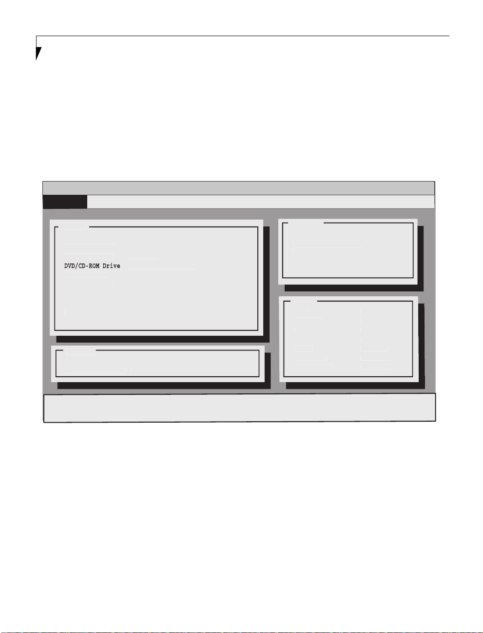
MAIN BIOS SCREEN – DISPLAYING CURRENT SYSTEM PARAMETERS
When the System Configuration Utility initially opens, a
screen appears which displays the current system parameters. When an item is changed in one of the submenus,
the change is immediately reflected in the main BIOS
screen. When you are in the SCU, the main BIOS screen
Each of the items in the main BIOS screen is addressed
in the applicable section of this document, depending
upon the submenu to which it belongs. Note that the
actual labels of some of the fields may vary, depending
upon the configuration of your system.
is always on screen, although portions of it may be
obscured by dropdown menus.
Insyde Software SCU May 6, 2002 02:10:05 PM
Startup
Memory Disks Components Exit
Devi
Flo
Drive A = 1.44 M
Primary MAster = 20
erial Port 1 = COM1, 3F8, IRQ
erial Port 2 = IR2, 2200, IRQ
Parallel Por
Boot Displa
Securit
P
Password on setup= Di
= UJDA720 DVD/CDR
= LPT1, 378, IRQ
= L
= Di
Pr
CPU = AMD Athlon(tm)
CPU Speed = 1200 MH
Memor
Exten
hadow = 176 K
R
Vi
T
l RAM = 128 M
Cache (Ext
= 640 K
=
= 208 K
= 16 M
= 256 K
Configure startup conditions
Figure 1. Main Menu
4
Page 5
Display Device
ate and
e
✓
go
✓
ast Boot
oot Device
d
d
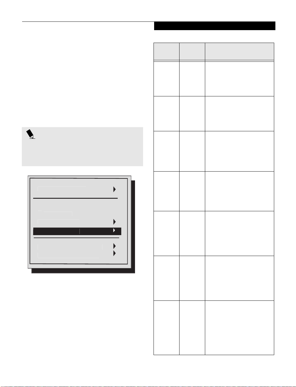
Startup Menu
STARTUP MENU
The Startup menu allows you to set basic information
about your system, including:
■
Change the system date and time
■
Enable or disable the boot logo when the system boots
up
■
Eliminate the boot memory test in order to speed up
system powering
■
Select the boot device order
■
Select the system display
■
Set Administrator and User Passwords
POINT
System Time and System Date can also be set from your
operating system without using the setup utility. Use
the calendar and time icon on your Windows Control
panel or type time or date from the MS-DOS prompt.
D
Splash Boot Lo
F
B
Set Admin passwor
Set User passwor
Tim
Figure 2. Startup Menu
Menu
Field
Date and
Time
Splash
Boot Logo
Fast Boot {Checked] Fast Boot allows the system to
Boot
Device
Display
Device
Set Admin
password
Default Description
--- When selected, opens the Date
[Checked] The Splash Boot Logo is the large
–— When selected, opens the Boot
–— When selected, opens the Display
–— When selected, opens the Set
and Time submenu, which allows
you to set the date and time for
your system. (For more details, see
Date and Time submenu later in
this section).
logo that appears on the screen
while the system is booting. This
item is enabled by default. To disable it, highlight the field, then
press [Enter}.
bypass the memory test when
booting up. This allows the system
to power up faster. This item is
enabled by default; to disable it,
highlight the field, then press
[Enter}.
Device submenu, which allows
you to determine the order of
devices your system will use when
booting up. (For more details, see
Boot Device submenu later in this
section).
Device submenu, which allows
you to determine which display
your system will use when booting: LCD, external monitor, or
both. (For more details, see Display Device submenu later in this
section).
Admin password submenu, which
allows you enter or change an
administrator’s password and to
determine when it will be
required. (For more details, see Set
Admin Password submenu later in
this section).
5
Set User
password
–— When selected, opens the Set
User password submenu, which
allows you enter or change a
user’s password and to determine
when it will be required. Note that
this field is greyed out unless an
Admin password has been
entered. (For more details, see Set
User Password submenu later in
this section).
Page 6

LifeBook A Series Notebook BIOS
ate and
e
8
y
ute
8
9
OK
Cancel
OK
l
Boot Device
oot Device
3rd Boot Device
oot Device
k
e
k
e
A
k
e
A
t
e
OK
Cance
n
D
T
T
e
Date and Time Submenu
The Date and Time submenu of the Startup menu allows
you to adjust or set the date and time for your system.
D
Tim
Month 5 Hour 1
Da
6 Min
Year 2002 Second 5
Figure 3. Date and Time submenu
To change the date or time, first select the field you want
to change with the cursor or the left and right arrows,
then use the up and down arrows to change the contents
of the field.
Click [OK] when you have finished changing the
contents, or [Cancel] to save the previous contents and
exit the window.
Boot Device Submenu
The Boot Device submenu of the Startup menu allows
you to determine the order of devices in which your
system will attempt to boot up.
Move between the three device windows using either the
[Ta b ] button or the left and right arrow buttons. To
change the selection within the device windows, use the
up and down arrow buttons.
This submenu also allows you to enable or disable the
PXE Boot option. PXE stands for Pre-boot Execution
Environment, which allows a computer to be loaded and
executed with a network program from a remote server
before booting the OS on the local hard drive. This eliminates the need to physically boot the computers with
floppy disks, as would normally be done.
The PXE Boot option is disabled by default. To enable it,
click on the field or tab to it and press the spacebar.
Display Device Submenu
The Display Device submenu of the Startup menu allows
you to select the device(s) you want to use when booting
up the system.
Display Devic
Boot Scree
*) LC
) CR
) LCD and CR
[ ] Video Expansion Mod
l
The defaults for the submenu follow:
1st Boot Device: Diskette A
2nd Boot Device: Hard Disk
3rd Boot Device: CD-ROM Drive
) Hard Dis
) CD-ROM Driv
*) Diskette
*) Hard Dis
) CD-ROM Driv
) Diskette
] PXE boo
1st B
2nd B
Figure 4. Boot Device submenu
) Hard Dis
*) CD-ROM Driv
) Diskette
Cance
Figure 5. Display Device submenu
Select one of the following:
LCD: Select LCD if you want to use the system display
when booting up the system.
CRT: Select CRT to use an external device such as a
television monitor when booting up the system.
LCD and CRT: Select this if you would like to use the
system display and an external device simultaneously.
Video Expansion Mode: Checking this box enables
video expansion, which controls spacing on the display.
When enabled, system displays with less than 1024 x 768
or 800 x 600 pixel resolution will cover the entire screen.
Resolution below 800 x 600 will fill the screen, but due to
the low resolution, may not be visually acceptable.
6
Page 7

S
OK
Cancel
assword:
.............
assword:
............
.
.
m
U
S
d
OK
Cancel
Use
assword:
.............
Use
assword:
............
.
Startup Menu
Set Admin Password Submenu
The Set Admin Password submenu allows you to enter a
new administrator’s password, change an old one, and
determine when to verify the password.
et Admin Password
Enter old ADMIN P
Enter new ADMIN P
Verify new ADMIN Password: ............
Verify password when..
[ ] Boot Syste
] Enter SC
Figure 6. Set Admin Password submenu
Entering/changing an administrator’s password
If an administrator’s password has not yet been set, the
Enter old ADMIN Password: prompt is greyed out. After
a password is registered, you will need to enter the password before you are allowed to proceed.
To enter an administrator’s password:
1., Type an alphanumeric password of up to eight characters into the Enter new ADMIN Password: field.
Be sure to use a password that you can remember
easily, or write it down.
2. Press the [Enter] key.
3. Enter the number again in the Ver if y n ew A DM IN
password: field, and press [Enter] again.
4. Check Boot System if you want to be prompted to
enter the password when you are booting the system;
check Enter SCU if you want to be prompted to
enter the password when you are entering the BIOS
System Configuration Utility.
5. Click [OK] if you are satisfied with your changes, or
[Cancel] if you want to exit the window without
saving any changes.
Set User Password Submenu
The Set User Password submenu allows you to enter a
new user’s password or change an old one.
et User Passwor
Enter old
Enter new
Verify new User Password: ............
Entering/changing a user’s password
If an administrator’s password has not yet been set, you
will not be allowed to enter a user’s password; the
submenu will not be accessible. If a user’s password has
not yet been set, the Enter old User Password: prompt is
greyed out. After a password is registered, you will need
to enter the password before you are allowed to proceed.
To enter a user’s password:
1. Type an alphanumeric password of up to eight characters into the Enter new User Password: field. Be
sure to use a password that you can remember easily,
or write it down.
2. Press the [Enter] key.
3. Enter the number again in the Verify new User pass-
word: field, and press [Enter] again.
4. Click [OK] if you are satisfied, or [Cancel] if you
want to exit the window without saving any changes.
Removing a user’s password
To remove a user’s password, simply type in your old
password at the Enter old User Password: prompt, then
press the [Enter] key three times, followed by the [OK]
button.
r P
r P
Figure 7. Set User Password submenu
Removing an administrator’s password
To remove an administrator’s password, simply type in
your old password at the Enter old ADMIN Password:
prompt, then press the [Enter] key three times, followed
by the [OK] button. Note that this not only removes
your Admin password, but also the User’s password.
7
Page 8

LifeBook A Series Notebook BIOS
y
OK
Cancel
e
M
M
M
MEMORY MENU
The Memory Menu allows you to change the amount of
extended memory that the system shares as Video
Memory. Increasing the amount of shared memory is
helpful if you use your computer primarily for graphicsintensive applications such as gaming or computeraided design, or if you frequently use the system with
simultaneous displays. (See Display Device Submenu on
page 6 for more information)
Shared Memory Submenu
To access the Shared Memory submenu, select Memory
from the top toolbar on the screen, then click Shared
Memory. The following window appears.
Shared Memor
Shared Memory Siz
) 8
*) 16
) 32
Figure 8. Shared Memory submenu
The Shared Memory submenu presents three choices:
8M, 16M, and 32M; 16M is the default selection. To
increase or decrease the amount of memory to be
shared, use the up and down arrows. When you have
made your selection, tap [OK] to accept it or [Cancel] to
exit the window without making any changes.
8
Page 9

✓
C
C
gs
__
y
ette
es
OK
Cancel
Settings
0
g
d
O
A
A
r
d
d
er
d
d
Disks Menu
DISKS MENU
The Disks menu allows you to set information about
your system’s hard- and floppy-disks, including:
■
Enable or disable internal floppy disk drive controller
■
Configure multiple diskette drives, if applicable.
■
Enable or disable the internal hard disk controller
■
Select the timing for hard disk drive and data transfers.
■
Enable or disable hard disk drive security
Internal FD
Disk
✓ Internal HD
IDE Settin
HDD Securit
Menu
Field
Internal
FDC
Diskette
Drives
Internal
HDC
IDE
Settings
HDD
Security
Default Description
[Checked] This item enables or disables the
--- When selected, opens the
[Checked] This item enables or disables the
–— When selected, opens the IDE Set-
[Unchecked] Enables or disables the hard disk
Figure 9. Disks Menu
Driv
internal floppy disk drive controller. It is enabled by default.
Diskette Drives submenu. This
would be used only if more than
one diskette drive is installed or
connected.
internal hard disk drive controller.
It is enabled by default.
tings submenu, which allows you
to select the timing and data
transfer rates of the hard disk
drive. (For more details, see IDE
Settings submenu later in this section).
drive security feature. It is disabled
by default. The HDD security feature attaches the administrator’s
password to the hard drive so that
if it is installed in a different system, the password will still be
required to access its contents.
IDE Settings Submenu
The IDE Settings submenu allows you to select the
timing speed for the system hard disk drive, as well as
the data transfer rates.
HDD Timin
) Standar
) Fast PI
) Multiword DM
) Ultra DM
(*) ATA-66/10
I/O 32 bit transfe
) Disable
*) Enable
HDD Block transf
) Disable
*) Enable
Figure 10. IDE Settings submenu
The IDE Settings submenu is divided into three sections:
HDD Timing:
■
Standard
■
Fast PIO
■
Multiword DMA
■
Ultra DMA
■
ATA-66/100
I/O 32 bit transfer:
This field is Enabled by default. When it is disabled, the
bit transfer is I/O 16 bit transfer.
HDD Block transfer:
This field is Enabled by default. When it is disabled,
system access to the hard disk drive is one sector per
Read/Write.
9
Page 10

LifeBook A Series Notebook BIOS
s
t
e
_
N
✓
er
ess Controller
✓
odem Controller
k
✓
p
COMPONENTS MENU
The Components menu allows you to select several of
the settings for your system, including the following:
■
Serial port (COM and IR) settings
■
Parallel (LPT) port settings
■
PS/2 device settings
■
Lid closure and Numlock settings
Serial Port
LPT Por
PS/2 Devic
Resume On LA
Lan Controll
Wirel
M
Keyboard Numloc
System Bee
Menu Field Default Description
PS/2 Device [Checked] When selected, opens the
Resume On
LAN
Lan
Controller
Wireless
Controller
Modem
Controller
LID --- When selected, opens the
[Unchecked] Enabling this feature
[Checked] Allows you to enable or
[Checked] Allows you to enable or
[Checked] Allows you to enable or
PS/2 Device submenu.
This allows you to enable
or disable the internal
pointing device. (For
more details, see PS/2
Device submenu later in
this section).
allows the system to
wake up when the internal LAN receives a special
message (“Magic
Packet”) while in Suspend
mode.
disable the internal LAN
controller.
disable the internal Wireless controller.
disable the internal
modem controller.
LID submenu. This determines what action the
system should take when
the lid is opened and
closed. (For more details,
see LID submenu later in
this section).
Menu Field Default Description
Serial Ports --- When selected, opens the
LPT Port --- When selected, opens the
Figure 11. Components Menu
Serial Ports submen u. This
allows you to select the
port addresses and interrupts for the COM and IR
ports. (For more details,
see Serial Ports submenu
later in this section).
LPT Port submenu. This
allows you to select the
port addresses and definitions for the parallel port.
(For more details, see LPT
Ports submenu later in
this section).
Keyboard
Numlock
System Beep [Checked] Enables or disables the
10
--- When selected, opens the
Keyboard Numlock submenu. This determines
whether the numerical
keypads are enabled or
disabled. (For more
details, see Keyboard
Numlock submenu later
in this section).
System beep.
Page 11

OK
Cancel
Serial Ports
4
d
3
4
3
:
d
4
3
4
3
:
LPT Port
7
e
5
7
ess
)
)
)
)
on
DMA Setting For ECP Mode
0
1
2
OK
Cancel
Components Menu
Serial Ports Submenu
The Serial Ports submenu allows you to select the port
addresses and interrupts for the COM and IR ports.
COM A I/O Settings
) Disable
(*) COM1, 3F8, IRQ
( ) COM2, 2F*, IRQ
( ) COM3, 3E8, IRQ
( ) COM4, 2E8, IRQ
Infrared Port I/O Settings
) Disable
( ) IR1, 2100, IRQ
(*) IR2, 2200, IRQ
( ) IR3, 2300, IRQ
( ) IR4, 2400, IRQ
Figure 12. Serial Ports submenu
The Serial Ports submenu consists of two sections:
■
COM A I/O Settings
■
Infrared Port I/O Settings
The COM A I/O Settings section allows you to select
which port address and interrupt will be used for COM
port A. COM1,3F8,IRQ4 is the default setting. To
select a different address and interrupt, use the up and
down arrow to choose a different one.
The Infrared Port I/O Settings section allows you to
select which port address and interrupt will be used for
COM port B (infrared port). IR2,2200,IRQ3 is the
default setting. To select a different address and interrupt, use the up and down arrow to choose a different
one.
LPT Port submenu
The LPT Port submenu allows you to select the port
addresses and interrupts for the internal printer port.
Port Addr
) Non
(*) LPT1, 378, IRQ
( ) LPT2, 278, IRQ
( ) LPT3, 3BC, IRQ
Figure 13. LPT Port submenu
The LPT Port submenu consists of three sections:
■
Port Address
■
Port Definition
■
DMA Settings For ECP Mode
The Port Address section allows you to select which port
address and interrupt will be used for the internal
parallel (LPT) port. This is also known as the parallel
port. LPT1,378,IRQ7 is the default setting. To select
a different address and interrupt, use the up and down
arrow to choose a different one.
The Port Definition section allows you to assign
advanced capabilities to an attached device that supports
the capabilities. Bidirectional (PS-2) is the
default setting. To select one of the other selections --
Standard AT (Centronics), Enhanced
Parallel (EPP), or Extended Capabilities
(ECP), use the up and down arrows to choose a
different one.
Note that Extended Capabilities (ECP)
must be selected in order to enable the DMA Setting For
ECP Mode section.
The DMA Setting For ECP Mode section allows you to
set the DMA channel for the parallel port if ECP Mode is
selected in the Port Definition section. DMA 0 is the
default setting.
Port Definiti
) Standard AT (Centronics
(*) Bidirectional (PS/2
) Enhanced Parallel (EPP
) Extended Capabilities (ECP
*) DMA
) DMA
) DMA
11
Page 12

LifeBook A Series Notebook BIOS
e
OK
Cancel
e
e
e
e
g
✓
g
OK
Cancel
✓
e
✓
d
k
OK
Cancel
s
f
o
PS/2 Device submenu
The PS/2 Device submenu allows you to enable or
disable the “hot-pluggability” of PS/2 devices. It also
allows you to determine the conditions under which the
internal PS/2 port is enabled.
PS/2 Devic
] Hotplu
Internal Pointing Devic
( ) Always Enabl
( ) Always Disabl
*) Auto Disabl
( ) Manual Settin
Figure 14. PS/2 Device submenu
The PS/2 Device submenu consists of a Hotplug
checkbox (enabled by default) and an Internal Pointing
Device section.
When Hotplug is checked, PS/2 devices can be plugged
in -- and will be recognized -- while the system is
running. When Always Disable or Manual
Setting are selected in the Internal Pointing Device
section, the Hotplug selection cannot be selected.
The Internal Pointing Device section consists of four
selections:
■
Always Enable
When selected, the internal pointing device (touchpad)
is enabled whether or not a PS/2 device is attached.
■
Always Disable
When selected, the internal pointing device (touchpad)
is never enabled.
■
Auto Disable
When selected, the internal pointing device (touchpad)
is disabled automatically when a PS/2 device is attached.
■
Manual Setting
When selected, the internal pointing device (touchpad)
operation is determined by desktop selection.
LID submenu
The LID submenu allows you to determine what action
the system takes when the lid is opened and closed.
] Lid closure suspen
] Lid open resum
Figure 15. LID submenu
There are two selections on the LID submenu:
■
Lid Closure Suspend:
This is enabled by default. When it is enabled, the system
will go into Suspend mode automatically when the lid is
closed. When it is disabled (unchecked), the system will
continue to run when the lid is closed.
■
Lid Open Resume:
This is enabled by default. When it is enabled, the system
will automatically resume operation when the lid is
opened. When it is disabled (unchecked), the system
requires user intervention in order to resume (by
pressing the On/Off button).
Keyboard Numlock submenu
The Keyboard Numlock submenu allows you to determine the state of the system’s numerical keypad.
Keyboard Numloc
Numerical Key Pad
) Of
) On
*) Aut
Figure 16. Keyboard Numlock submenu
The Keyboard Numlock submenu offers three choices:
Off, On, and Auto. Auto is the default selection.
When Off or On are selected, the numerical keypads are
disabled or enabled, respectively. When Auto is
selected, the state of the numerical keypads is determined by the system.
12
Page 13

Save and Reboot
)
gs
gs
o
S
t
OK
Cancel
ess <O
t
.
!
)
OK
Cancel
.
!
gs
OK
Cancel
p
?
gs
OK
Cancel
p
?
Exit Menu
EXIT MENU
The Exit Menu provides information about the BIOS,
and allows you to exit the utility, reset defaults, or restore
the system to the settings it had before entering the SCU.
Exit (No Save
Default Settin
Restore Settin
Version Inf
Figure 17. Exit menu
Exit Menu consists of five submenus, as detailed below:
Save and Reboot submenu
The Save and Reboot submenu allows you to save any
settings you have made to the BIOS (by clicking [OK].
When you click [OK], you will exit the utility and the
system will reboot.
ave and Reboo
Pr
setup parameters to CMOS RAM
The computer will be rebooted!!
K> to save the curren
Exit (No Save
Press <OK> to Exit the SCU
The current settings will not be saved!!
Figure 19. Exit (No Save) submenu
Default Settings submenu
The Default Settings submenu allows you to restore the
BIOS settings to the original factory default settings (by
clicking [OK]. When you click [OK], you will exit the
utility and the default settings will be restored.
Default Settin
Do you wish to change the current setu
to the system default values
Figure 20. Default Settings submenu
Restore Settings submenu
The Restore Settings submenu allows you to exit the
utility without saving any changes (by clicking [OK].
When you click [OK], you will exit the utility and restore
your custom settings.
Figure 18. Save and Reboot submenu
Exit (No Save) submenu
The Exit (No Save) submenu allows you to exit the
utility without saving any changes that you made during
the current session (by clicking [OK]. When you click
[OK], you will exit the utility.
Restore Settin
Do you wish to change the current setu
to the original custom values
Figure 21. Restore Settings submenu
13
Page 14

LifeBook A Series Notebook BIOS
o
OK
.
.
/26/
Version Info submenu
The Version Info submenu is for display only, and indicates information about the BIOS on your system.
Version Inf
Copyright 1983-1999 Insyde Software
All Rights Reserved
Version 1.02 Date: 04
Figure 22. Version Info submenu
02
14
 Loading...