

Fujitsu 9319357041 Installation Manual
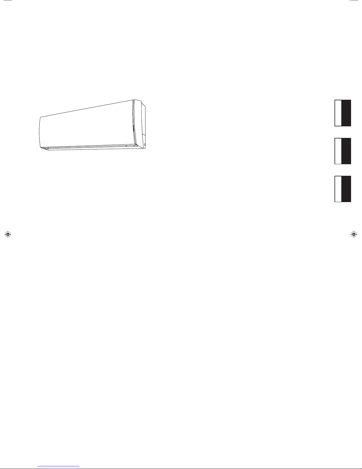
AIR CONDITIONER
INSTALLATION MANUAL
For authorized service personnel only.
EnglishFrançaisEspañol
MANUEL D’INSTALLATION
Pour le personnel agréé uniquement.
MANUAL DE INSTALACIÓN
Solo para personal autorizado.
PART NO. 9319357041

Contents
1. SAFETY PRECAUTIONS ..........................................................................................2
2. ABOUT THE UNIT .....................................................................................................2
3. GENERAL SPECIFICATION .....................................................................................3
4. ELECTRICAL REQUIREMENT .................................................................................4
5. SELECTING THE MOUNTING POSITION ...............................................................4
6. INSTALLATION WORK .............................................................................................4
7. ELECTRICAL WIRING .............................................................................................7
8. FINISHING ................................................................................................................8
9. FRONT PANEL REMOVAL AND INSTALLATION .....................................................9
10. TEST RUN .................................................................................................................9
11. REMOTE CONTROLLER INSTALLATION ..............................................................10
12. OPTIONAL KIT INSTALLATION (UTY-TWBXF) ......................................................10
13. SELECTING THE REMOTE CONTROLLER SIGNAL CODE .................................11
14. FUNCTION SETTING..............................................................................................12
15. CUSTOMER GUIDANCE ........................................................................................13
16. ERROR CODES ......................................................................................................13
Branch box which is specifi ed in this manual is the equipment to support the indoor unit •
of multi-connection type.
TION
1. SAFETY PRECAUTIONS
1.1. IMPORTANT! Please read before starting
This air conditioning system meets strict safety and operating standards.
As the installer or service person, it is an important part of your job to install or service the
system so it operates safely and effi ciently.
For safe installation and trouble-free operation, you must:
• Carefully read this instruction booklet before beginning.
• Follow each installation or repair step exactly as shown.
• Observe all local, state, and national electrical codes.
• Pay close attention to all danger and caution notices given in this manual.
WARNING:
CAUTION:
• Hazard alerting symbols
Electrical
If Necessary, Get Help
These instructions are all you need for most installation sites and maintenance conditions.
If you require help for a special problem, contact our sales/service outlet or your certifi ed
dealer for additional instructions
In Case of Improper Installation
The manufacturer shall in no way be responsible for improper installation or maintenance
service, including failure to follow the instructions in this document.
1.2. SPECIAL PRECAUTIONS
When Wiring
ELECTRICAL SHOCK CAN CAUSE SEVERE PERSONAL INJURY OR DEATH. ONLY A
QUALIFIED, EXPERIENCED ELECTRICIAN SHOULD ATTEMPT TO WIRE THIS SYSTEM.
• Do not supply power to the unit until all wiring and tubing are completed or reconnected
and checked.
• Highly dangerous electrical voltages are used in this system. Carefully refer to the wiring diagram and these instructions when wiring. Improper connections and inadequate
grounding can cause accidental injury or death.
• Ground the unit following local electrical codes.
• Connect all wiring tightly. Loose wiring may cause overheating at connection points
and a possible fi re hazard.
When Transporting
Be careful when picking up and moving the indoor and outdoor units. Get a partner to
help, and bend your knees when lifting to reduce strain on your back. Sharp edges or thin
aluminum fi ns on the air conditioner can cut your fi ngers.
This symbol refers to a hazard or unsafe practice which can result in
severe personal injury or death.
This symbol refers to a hazard or unsafe practice which can result in
personal injury and the potential for product or property damage.
Safety/alert
.
When Installing...
...In a Ceiling or Wall
Make sure the ceiling/wall is strong enough to hold the unit’s weight. It may be necessary
to construct a strong wood or metal frame to provide added support
...In a Room
Properly insulate any tubing run inside a room to prevent “sweating” that can cause dripping and water damage to walls and fl oors.
...In an Area with High Winds
Securely anchor the outdoor unit down with bolts and a metal frame.
Provide a suitable air baffl e.
...In a Snowy Area (for Heat Pump-type Systems)
Install the outdoor unit on a raised platform that is higher than drifting snow.
When Connecting Refrigerant Tubing
• Keep all tubing runs as short as possible.
• Use the fl are method for connecting tubing.
• Apply refrigerant lubricant to the matching surfaces of the fl are and union tubes before
connecting them, then tighten the nut with a torque wrench for a leak-free connection.
• Check carefully for leaks before opening the refrigerant valves.
When Servicing
• Turn the power OFF at the main circuit breaker panel before opening the unit to check
or repair electrical parts and wiring.
• Keep your fi ngers and clothing away from any moving parts.
• Clean up the site after you fi nish, remembering to check that no metal scraps or bits of
wiring have been left inside the unit being serviced.
• After installation, explain correct operation to the customer, using the operating manual.
.
WARNING
Never touch electrical components immediately after the power supply has been turned
off. Electric shock may occur. After turning off the power, always wait 5 minutes before
touching electrical components.
If refrigerant leaks while work is being carried out, ventilate the area. If the refrigerant
comes in contact with a fl ame, it produces a toxic gas.
CAUTION
Do not attempt to install the air conditioner or a part of the air conditioner by yourself.
This unit must be installed by qualifi ed personnel with a capacity certifi cate for handling
refrigerant fl uids. Refer to regulation and laws in use on installation place.
This unit is part of a set constituting an air conditioner. It must not be installed alone or
with non-authorized by the manufacturer.
Always use a separate power supply line protected by a circuit breaker operating on all
wires with a distance between contact of 3 mm (1/8 in.) for this unit.
The unit must be correctly earthed (grounded) and the supply line must be equipped
with a differential breaker in order to protect the persons.
The units are not explosion proof and therefore should not be installed in explosive
atmosphere.
When moving, consult authorized service personnel for disconnection and installation
of the unit.
Do not place any other electrical products or household belongings under indoor unit
or outdoor unit.
Dripping condensation from the unit might get them wet, and may cause damage or
malfunction of your property.
2. ABOUT THE UNIT
2.1. Precautions for using R410A refrigerant
The basic installation work procedures are the same as conventional refrigerant (R22)
models.
However, pay careful attention to the following points:
Since the working pressure is 1.6 times higher than that of conventional refrigerant
(R22) models, some of the piping and installation and service tools are special. (See
the table below.)
Especially, when replacing a conventional refrigerant (R22) model with a new refrigerant
R410A model, always replace the conventional piping and fl are nuts with the R410A piping
and fl are nuts.
Models that use refrigerant R410A have a different charging port thread diameter to prevent erroneous charging with conventional refrigerant (R22) and for safety. Therefore,
check beforehand. [The charging port thread diameter for R410A is 1/2 inch.]
Be more careful that foreign matter (oil, water, etc.) does not enter the piping than with
refrigerant (R22) models. Also, when storing the piping ,securely seal the opening by
pinching, taping, etc.
When charging the refrigerant, take into account the slight change in the composition of
the gas and liquid phases. And always charge from the liquid phase where refrigerant
composition is stable.
En-2
2.2. Special tools for R410A
Tool name Contents of change
Pressure is high and cannot be measured with a conven-
Gauge manifold
Charge hose
Vacuum pump
Gas leakage detector Special gas leakage detector for HFC refrigerant R410A.
Copper pipes
It is necessary to use seamless copper pipes and it is desirable that the amount of residual
oil is less than 40 mg/10 m (0.004 oz/100 ft.). Do not use copper pipes having a collapsed,
deformed or discolored portion (especially on the interior surface). Otherwise, the expansion
value or capillary tube may become blocked with contaminants.
As an air conditioner using R410A incurs pressure higher than when using R22, it is necessary to choose adequate materials.
Do not use the existing (for R22) piping and fl are nuts.
If the existing materials are used, the pressure inside the refrigerant cycle will rise and
cause failure, injury, etc. (Use the special R410A materials.)
When installing and relocating the air conditioner, do not mix gases other than the
specifi ed refrigerant (R410A) to enter the refrigerant cycle.
If air or other gas enters the refrigerant cycle, the pressure inside the cycle will rise to
an abnormally high value and cause failure, injury, etc.
2.3.
For authorized service personnel only.
For the air conditioner to operate satisfactorily, install it as outlined in this installation
manual.
Connect the indoor unit and outdoor unit or branch box with the air conditioner piping
and cables available from your local distributor. This installation manual describes the
correct connections using the installation set available from your local distributor.
Do not turn on the power until all installation work is complete.
tional (R22) gauge. To prevent erroneous mixing of other
refrigerants, the diameter of each port has been changed.
It is recommended the gauge with seals -0.1 to 5.3 MPa
(30 inHg to 768 psi) for high pressure.
-0.1 to 3.8 MPa (30 inHg to 551 psi) for low pressure.
To increase pressure resistance, the hose material and base
size were changed.
A conventional vacuum pump can be used by installing a
vacuum pump adapter.
WARNING
WARNING
Name and Shape
Remote controller
Battery
Seal A
It is used when the diameter of
gas pipe is Ø12.70 or more.
It is necessary when using AS15.
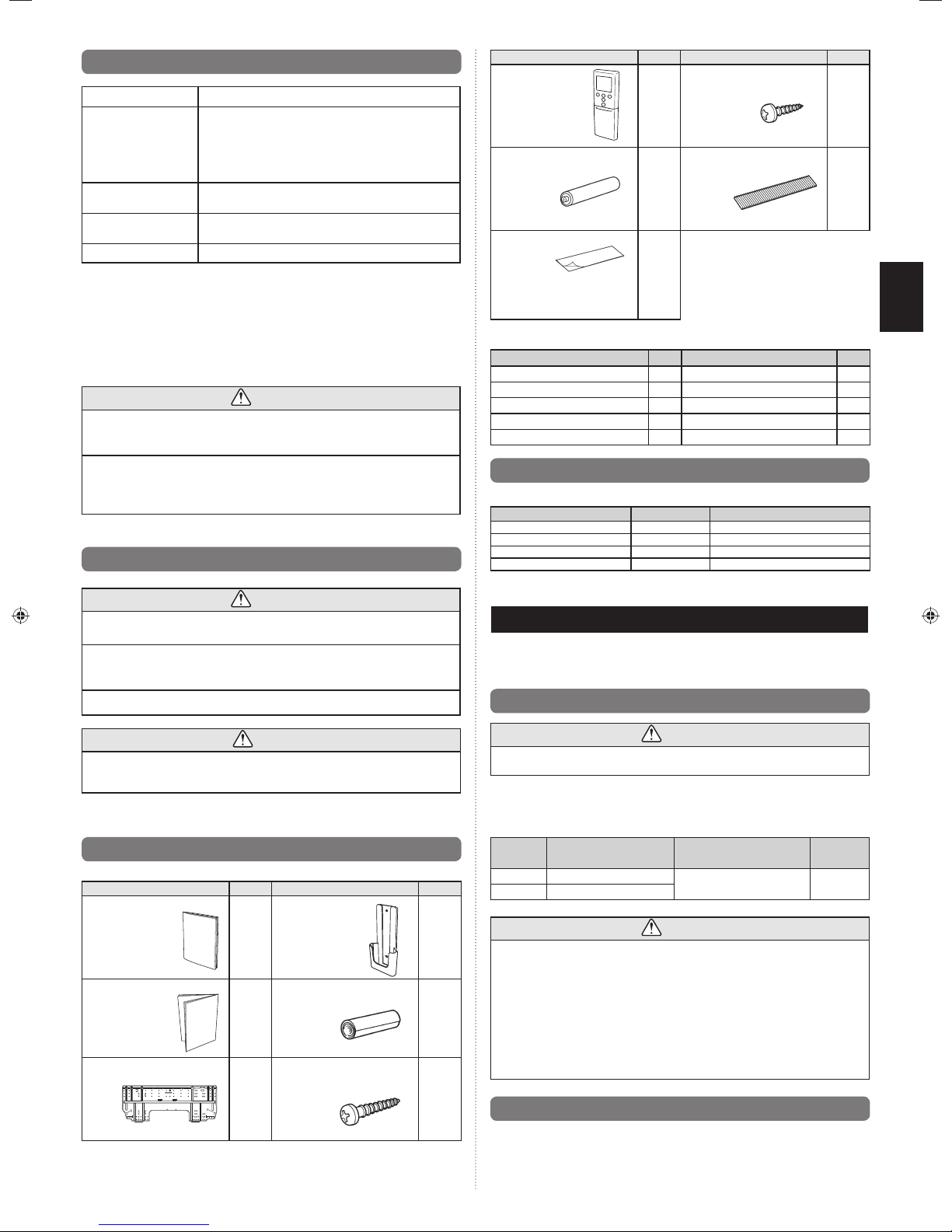
The following items are necessary to install this air conditioner. (The items are not included with the air conditioner and must be purchased separately.)
Q’ty
1
2
1
Name and Shape
Tapping screw
(small)
Air cleaning filter
Q’ty
2
2
Name Q’ty Name Q’ty
Connection pipe assembly 1 Wall cap 1
Connection cable (4-conductor)
Wall pipe 1 Drain hose 1
Decorative tape 1 Tapping screws 1 set
Vinyl tape 1 Sealant 1
1 Saddle 1 set
2.5. Optional parts
Refer to each installation manual for the method of installing optional parts.
Parts name Model No. Application
Wired remote controller * UTY-RNNUM For air conditioner operation
Simple remote controller * UTY-RSNUM For air conditioner operation
External connect kit * UTY-XWZXZ5 For control input/output port
Communication kit UTY-TWBXF For the installation of optional parts
* Optional communication kit is necessary for the installation.
3. GENERAL SPECIFICATION
This installation manual briefl y outlines where and how to install the air conditioning system. Please
read over the entire set of instructions for the indoor and outdoor units and make sure all accessory
parts listed are with the system before beginning.
3.1. Type of copper pipe and insulation material
CAUTION
This installation manual describes how to install the indoor unit only.
To install the outdoor unit or branch box, refer to the installation manual included with
the outdoor unit or branch box.
• Be careful not to scratch the air conditioner when handling it.
• After installation, explain correct operation to the customer, using the operating manual.
2.4. Accessories
The following installation accessories are supplied. Use them as required.
Name and Shape
Operating manual
Installation manual
(This manual)
Wall hook bracket
Q’ty
1
1
1
Name and Shape
Remote controller
holder
Cloth tape
Tapping screw
(big)
Q’ty
1
1
5
CAUTION
Refer to the installation manual for the outdoor unit for description of allowable pipe length
and height difference.
Selecting pipe sizes
The diameters of the connection pipes according to the capacity of the indoor unit.
Refer to the following table for the proper diameters of the connection pipes between the
indoor unit and outdoor unit or branch box.
Indoor unit
capacity
Gas pipe outside diameter
[mm (in.)]
9, 12 9.52 (3/8)
15 12.70 (1/2)
Liquid pipe outside diameter
[mm (in.)]
6.35 (1/4)
Thickness
[mm (in.)]
0.8
(0.0315)
CAUTION
Install heat insulation around both the gas and liquid pipes. Failure to do so may
cause water leaks.
Use heat insulation with heat resistance above 120 °C (248 °F). (Reverse cycle model
only.)
In addition, if the humidity level at the installation location of the refrigerant piping is
expected to exceed 70%, install heat insulation around the refrigerant piping. If the
expected humidity level is 70-80%, use heat insulation that is 15 mm (19/32 in.) or
thicker and if the expected humidity exceeds 80%, use heat insulation that is 20 mm
(25/32 in.) or thicker.
If heat insulation is used that is not as thick as specifi ed, condensation may form on the surface
of the insulation.
In addition, use heat insulation with heat conductivity of 0.045 W/(m•K) or less 20 °C (68 °F)
.
3.2. Additional materials required for installation
A. Refrigeration (armored) tape
B. Insulated staples or clamps for connecting wire (See your local electrical codes.)
C. Putty
D. Refrigeration lubricant
E. Clamps or saddles to secure refrigerant piping
En-3
4. ELECTRICAL REQUIREMENT
The indoor unit is powered from the outdoor unit or branch box. Do not power indoor unit
from separate power source.
WARNING
Refer to local codes for acceptable cable type.
5. SELECTING THE MOUNTING POSITION
Decide the mounting position with the customer as follows:
6. INSTALLATION WORK
6.1. Installation dimensions
120 mm (4-23/32 in.) or over *
110 mm (4-11/32 in.)
or over **
Wall hook
bracket
110 mm (4-11/32 in.) or over **
5.1. Indoor unit
(1) Install the indoor unit level on a strong wall which is not subject to vibration.
(2) The inlet and outlet ports should not be obstructed: the air should be able to blow all
over the room.
(3)
Install the unit a dedicated electrical branch circuit.
(4)
Do not install the unit where it will be exposed to direct sunlight.
(5)
Install the unit where connection to the outdoor unit or branch box is easy.
(6) Install the unit where the drain pipe can be easily installed.
(7) Take servicing, etc. into consideration and leave the spaces shown in “6.1. Installation
dimensions”. Also install the unit where the fi lter can be removed.
Correct initial installation location is important because it is diffi cult to move unit after it is
installed.
WARNING
Select installation locations that can properly support the weight of the indoor. Install the
units securely so that they do not topple or fall.
CAUTION
Do not install the unit in the following areas:
•
Area with high salt content, such as at the seaside. It will deteriorate metal parts, causing the parts
to fail or the unit to leak water.
•
Area fi lled with mineral oil or containing a large amount of splashed oil or steam, such as a
kitchen.
It will deteriorate plastic parts, causing the parts to fail or the unit to leak water.
•
Area that generates substances that adversely affect the equipment, such as sulfuric gas, chlorine
gas, acid, or alkali.
It will cause the copper pipes and brazed joints to corrode, which can cause refrigerant leakage.
•
Area that can cause combustible gas to leak, contains suspended carbon fi bers or fl ammable
dust, or volatile infl ammables such as paint thinner or gasoline.
•
If gas leaks and settles around the unit, it can cause a fi re.
•
Area where animals may urinate on the unit or ammonia may be generated.
Do not use the unit for special purposes, such as storing food, raising animals, growing
plants, or preserving precision devices or art objects.
It can degrade the quality of the preserved or stored objects.
Do not install where there is the danger of combustible gas leakage.
Do not install the unit near a source of heat, steam, or fl ammable gas.
Install the unit where drainage does not cause any trouble.
Install the indoor unit, outdoor unit, branch box, power supply cable, transmission cable,
and remote control cable at least 1 m (40 in.) away from a television or radio receivers.
The purpose of this is to prevent TV reception interference or radio noise.
(Even if they are installed more than 1 m (40 in.) apart, you could still receive noise
under some signal conditions.)
If children under 10 years old may approach the unit, take preventive measures so that
they cannot reach the unit.
Install the indoor unit on the wall where the height from the fl oors more than 1.8 m (70 in.)
1.8 m (70-7/8 in.)
1.5 m (59-1/16 in.)
or over
Remote
controller
* The distance between the wall hook bracket and the ceiling
should be 120 mm (4-23/32 in.) or more.
** The side next to the sidewall must follow the size indicated in the
figure.
or over
(Wall cap)
Remote controller
holder
Tapping screw
(small)
6.2. Indoor unit piping direction
The piping can be connected in the 6 directions indicated in the following.
When the piping is connected in direction (2) , (3) , (4) or (5) , cut along the piping groove
in the side of the under cover with a hacksaw.
(2) Right
outlet
(Rear)
(1) Right rear outlet
(3) Right bottom outlet
(4) Left bottom outlet
(5) Left
(6) Left rear
outlet
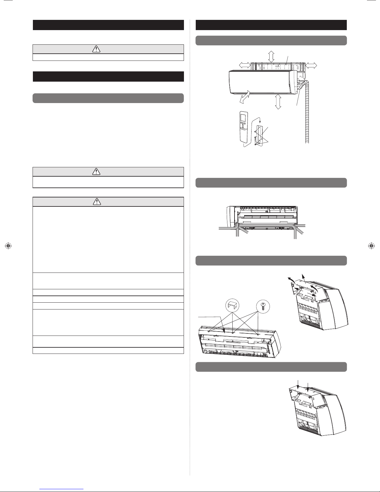
6.3. Under cover removal
(1) Remove the screw caps and screws from the
under cover (in each of 3 places).
(2) Lift up the central part of the under cover.
(3) Release the tabs by pressing on the side of the
under cover (in 2 places on the side).
Remove the under cover while turning it.
(4)
Screw cap
Under cover
(1)
.
Screw
(1)
(1)
(2)
(4)
(4)
(3)
outlet
En-4
6.4. Under cover installation
(1) Push the tabs on the side of the under cover into
the base (in 2 places on the side).
(2) Press in the top parts of the triangle markings on
the under cover (in 2 places).
(3) Attach the screws (in 3 places).
(4) Attach the screw caps (in 3 places).
(2)
(2)
(1)
(1)
(1)

6.5. Cutting the knockout hole
Cutting the knockout hole for piping on under cover:
The piping can be connected in the 6 directions indicated in the following.
When the piping is connected in direction (2), (3), (4) or (5), use a cutting tool to cut along
the groove for the piping that will coming out of the under cover.
For (5) Left outlet
For (4) Left bottom outlet
For (3) Right bottom outlet
For (2) Right outlet
6.6. Cutting the hole in the wall for the connecting piping
(1) Cut a 65-mm (2-9/16-in.) diameter hole in the wall at the position shown in the
following.
(2) Cut the hole so that the outside end is lower [5 to 10 mm (3/16 to 13/32 in.)] than the
inside end.
(3) Always align the center of the wall hole. If misaligned, water leakage will occur.
(4)
Cut the wall pipe to match the wall thickness, stick it into the wall cap, fasten the cap with
vinyl tape, and stick the pipe through the hole.
(5) For left piping and right piping, cut the hole a little lower so that drain water will fl ow
freely.
Center mark
Wall hook bracket
Center mark
6.8.
Forming the drain hose and pipe
[Rear piping, Right piping, Bottom piping]
• Install the indoor unit piping in the direction of the wall hole and bind the drain hose
and pipe together with vinyl tape.
• Install the piping so that the drain hose is at the bottom.
• Wrap the pipes of the indoor unit that are visible from the outside with decorative tape.
[For Left rear piping, Left piping]
Interchange the drain cap and the drain hose.
CAUTION
Insert drain hose and drain cap securely. Drain should slope down to avoid water
leakage.
When inserting, be sure not to attach any material besides water. If any other
material is attached, it will cause deterioration and water leakage.
After removing drain hose, be sure not to forget mounting drain cap.
Be sure to fi x the drain hose with tape to the bottom of piping.
Prevent drain water freezing under low temperature environment.
When installing indoor unit’s drain hose outdoors, necessary measure for frost
protection should be taken to prevent drain water freezing.
Under low temperature environment [when outdoor temperature under 0 °C (32 °F)],
after cooling operation is executed, water in the drain hose could be frozen. Once
drain water is frozen, the drain hose will be blocked and water leakage may result at
the indoor unit.
Installation method of Drain cap
Use a hexagonal wrench 4 mm (5/32 in.) at opposite
side to insert the drain cap, till the drain cap contacts
the tip of drain cock.
No gap
Hexagonal
wrench
Drain
cock
Drain cap
65-mm (2-9/16-in.) dia. hole
Fasten with
vinyl tape
65-mm (2-9/16-in.) dia. hole
5 to 10 mm
(3/16 to 13/32 in.) low
Wall pipe*
Wall cap*
(Inside)
Wall
(Outside)
*Field supplied
WARNING
If the wall pipe is not used, the cable interconnecting the indoor unit(s) and outdoor unit
or branch box may touch metal and cause electric discharge.
6.7. Installing the wall hook bracket
(1) Install the wall hook bracket so that it is correctly positioned horizontally and vertically.
If the wall hook bracket is titled, water will drip to the fl oor.
(2) Install the wall hook bracket so that it is strong enough to support the weight of the
unit.
•
Fasten the wall hook bracket to the wall with 5 or more screws through the holes near the
outer edge of the bracket.
•
Check that there is no rattle at the wall hook bracket.
Install the wall hook bracket level, both horizontally and vertically.
Wall hook bracket
Tapping screw
CAUTION
Right piping
Bind with vinyl tape
Refrigerant pipes (top)
Rear piping
Bottom piping
Removal method of drain hose
Remove the screw at the left of
drain hose and pull out drain hose.
Drain fixture
Drain hose
• Please hold around the joint of the drain hose during working.
As the screw is inside, be sure to use screwdriver treated with magnet.
•
•
For left piping and left rear piping, align the marks on the wall hook bracket and shape the
connection pipe.
• Bend the connection piping at a bend radius of 70 mm (2-3/4 in.) or more and install no
more than 35 mm (1-3/8 in.) from the wall.
•
After passing the indoor piping and drain hose through the wall hole, hang the indoor unit on
the hooks at the top and bottom of the wall hook bracket.
Indoor unit drain hose (bottom)
Indoor unit
drain hose
Drain cap
Remove the drain cap by pulling
at the projection at the end of the
cap with pliers, etc.
Installation method of drain hose
Vertically insert the drain hose toward the
inside, so that the drain fi xture (white) can ac-
curately align with the screw hole around the
drain cock.
After inserting and before replacing, please
reinstall and fi x the removed screws.
Screw
Screw hole
For left outlet piping,
cut off the piping
outlet cutting groove
with a hacksaw.
Drain cock
Drain fixture
Drain hose
Screw
En-5
 Loading...