

Page 1

DESKPOWER 8000 Series User’s Manual
Fujitsu endeavours to ensure that the information in this document is correct, but accepts no liability for any
error or omission in the same. Any procedures described in this document for operating Fujitsu products
should be read and understood by the operator before such products are used. To ensure that Fujitsu
products function without risk to safety and health, such procedures should be strictly observed by the
operator. The development of Fujitsu products and services is continuous and published information may not
be up to date. Any particular issue of a product may contain facilities not described herein. It is important to
check the current position with Fujitsu. Specifications and statements as to performance in this document are
Fujitsu estimates intended for general guidance. They may require adjustment in particular circumstances
and should therefore not be taken as formal offers or commitments.
DESKPOWER is a trademark of Fujitsu Limited. The following are registered trademarks of Microsoft
Corporation: MS, MS-DOS, Windows
Windows Me, Windows
the registered trade mark of Intel Corporation. Phoenix and the Phoenix logo are registered trademarks of
Phoenix Technologies, Ltd.
All Rights Reserved. Copyright
The use of screens is permitted by Microsoft Corporation in the United States.
All other products are trademarks or registered trademarks of their respective companies.
© Copyright 2001 Fujitsu Limited. All rights reserved. No part of this publication may be copied, reproduced,
or translated without the prior written consent of Fujitsu Limited. No part of this publication may be stored or
transmitted in any electronic form without the written consent of Fujitsu Limited.
®
2000. Intel 850, Pentium™ and MMX™ technology , Celeron, Pentium II, III and IV are
®
NT, Windows® for Workgroups, Windows® 95, Windows® 98,
©
Fujitsu Limited, 2001
DECLARATION OF CONFORMITY
according to FCC Part 15 Class B
Responsible Party Name : Fujitsu PC ( Asia ) Pte Ltd
Website : www.fujitsu-pc-asia.com/contactus
Declares that product: Model : DESKPOWER 8000
Complies with Part 15 Class B
of the FCC Rules.
This device complies with Part 15 Class B of the FCC Rules. Operations are subject to the following two conditions:
(1) This device must not be allowed to cause harmful interference, (2) This device must accept any interference
received, including interference that may cause undesired operation.
Page 2

IMPORTANT SAFETY INSTRUCTIONS
1. Read these instructions carefully. Save these instructions for future reference.
2. Follow all warnings and instructions marked on the product.
3. Unplug this product from the wall outlet before cleaning. Do not use liquid cleaners or
aerosol cleaners. Use a damp cloth for cleaning.
4. Do not use this product near water.
5. Do not place this product on an unstable cart, stand, or table. The product may fall, causing
serious damage to the product.
6. Slots and openings in the cabinet and the back or bottom are provided for ventilation; to
ensure reliable operation of the product and to protect it from overheating, these openings
must not be blocked or covered. The openings should never be blocked by placing the
product on a bed, sofa, rug, or other similar surface. This product should never be placed
near or over a radiator or heat register, or in a built-in installation unless proper ventilation is
provided.
7. This product should be operated from the type of power indicated on the marking label. If
you are not sure of the type of power available, consult your dealer or local power company.
8. This product is equipped with a 3-wire grounding-type plug, a plug having a third (grounding)
pin. This will only plug into a grounding-type power outlet. This is a safety feature. If you are
unable to insert the plug into the outlet, contact your electrician to replace your obsolete
outlet. Do not defeat the purpose of the grounding-type plug.
9. Do not allow anything to rest on the power cord. Do not locate this product where persons
will walk on the cord.
10. If an extension cord is used with this product, make sure that the total ampere rating of the
equipment plugged into the extension cord does not exceed the extension cord ampere
rating. Also, make sure that the total rating of all products plugged into the wall outlet does
not exceed 15 amperes.
11. Never push objects of any kind into this product through cabinet slots as they may touch
dangerous voltage points that could result in a fire or electric shock. Never spill liquid of any
kind on the product.
12. Do not attempt to service this product yourself, as opening or removing covers may expose
you to dangerous voltage points or other risks. Refer all servicing to qualified service
personnel.
Page 3

13. Unplug this product from the wall outlet and refer servicing to qualified service personnel
under the following conditions:
a. When the power cord or plug is damaged or frayed.
b. If liquid has been spilled into the product.
c. If the product has been exposed to rain or water.
d. If the product does not operate normally when the operating instructions are followed.
Adjust only those controls that are covered by the operating instructions since improper
adjustment of other controls may result in damage and will often require extensive work
by a qualified technician to restore the product to normal condition.
e. If the product has been dropped or the cabinet has been damaged.
f. If the product exhibits a distinct change in performance, indicating a need for service.
14. CAUTION. When replacing the battery, be sure to install it with the polarities in the
correct position. There is a danger of explosion if the battery is replaced with an
incorrect type or is mistreated. Do not recharge, disassemble or dispose of in fire.
Replace only with the same or equivalent type recommeded by the manufacturer.
Dispose of the used battery according to the manufacturer’s instructions.
15. Use only the proper type of power supply cord set (provided in your accessories box) for this
unit. It should be a detachable type: UL listed/CSA certified, BS1363,ASTA,SS145 certified,
rated 10A 250V minimum, VDE approved or its equivalent. Maximum length is 15 feet (4.6
meters).
Page 4
■ Greetings
We thank you for purchasing the Fujitsu DESKPOWER 8000 personal computer.
This manual explains how to use the hardware of the DESKPOWER 8000.
Please read this manual carefully to ensure correct use of the PC.
This unit may malfunction if the power source is interrupted suddenly, for example, due to lightning.
Fujitsu recommends the use of an AC non-interruptible power supply unit.
(Based on guidelines for the prevention of sudden voltage interruptions by Japan Electronic
Industry Development Association (JEIDA).
This unit is class B information technology equipment based on the Voluntary Control Council for
Interference (VCCI) standard by Information Technology Equipment and may create interference
if used near radio or television receivers.
Use the unit in accordance with information provided in the manual.
This unit conforms to the Personal Computer Industry Standard (PC-11-1988) of the Japan
Electronic Industry Development Association (JEIDA).
This unit conforms to the harmonic guideline.
Because this product includes cargo based on the “Foreign Exchange and Foreign Trade
Control Act,” the export of this product may require permission in accordance with said act.
Fujitsu, who is a participant of the International Energy Star Program,
determines that this product conforms to the International Energy Star
Program Standard.
The International Energy Star Program is an international program for
promoting energy conservation of office equipment such as computers and
strives to develop and promote products capable of efficient energy use. This program is open
to all manufacturers, and the products to be developed include computers, displays, printers,
facsimiles, and copy machines. The same standard and markings ( ) are used among
participating countries.
The energy-saving function of this product, however, may not be applicable because of
limitations with the operating system (such as Windows NT).
Page 5
■ Conventions used in this manual
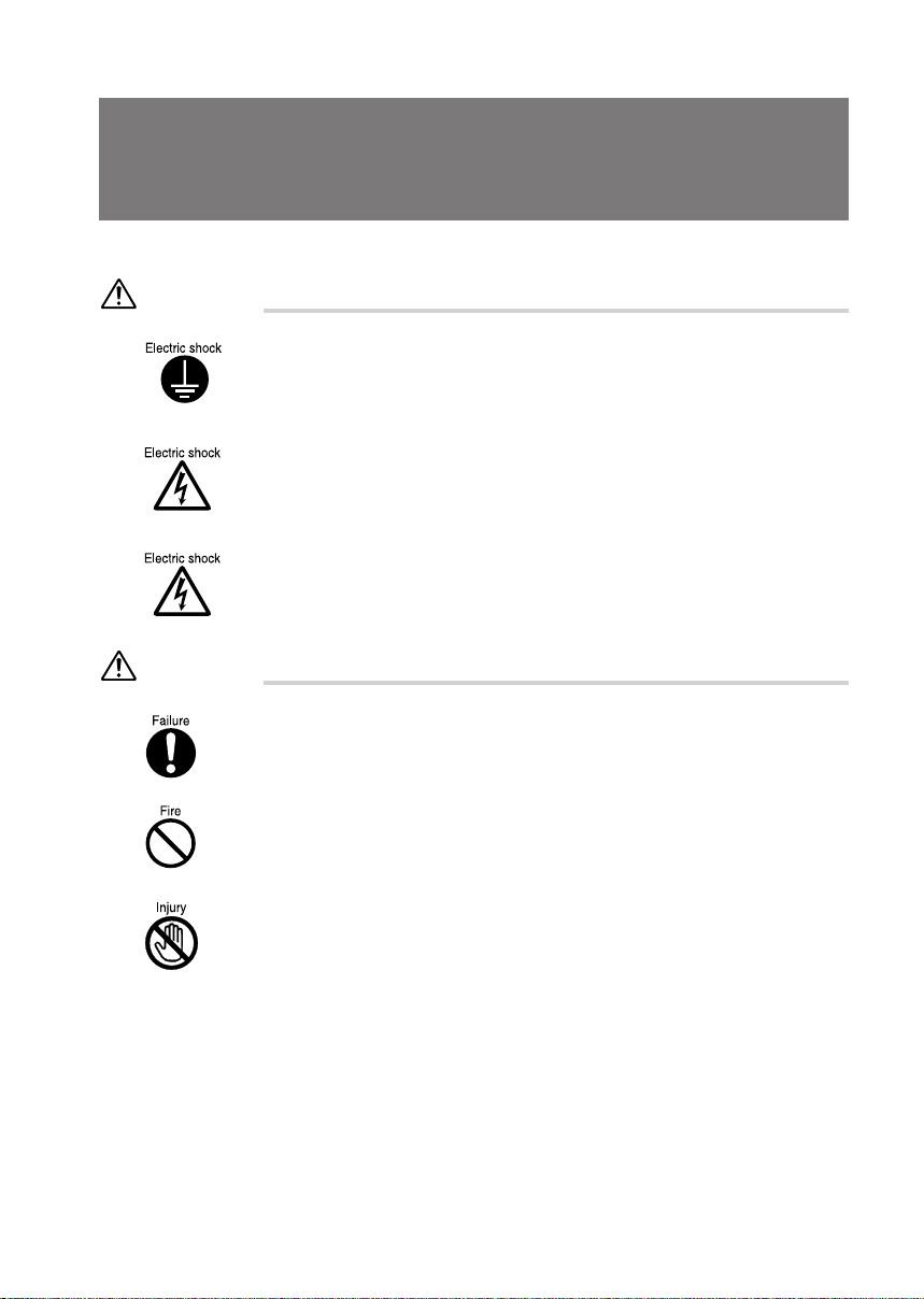
● Warning icons
Various icons and icon/word combinations are used in this manual to encourage users to use the
equipment so as to minimize personal risk and prevent property damage. The icons are explained
as follows. The user should be familiar with the icons before responding to the corresponding
instructions.
WARNING
CAUTION
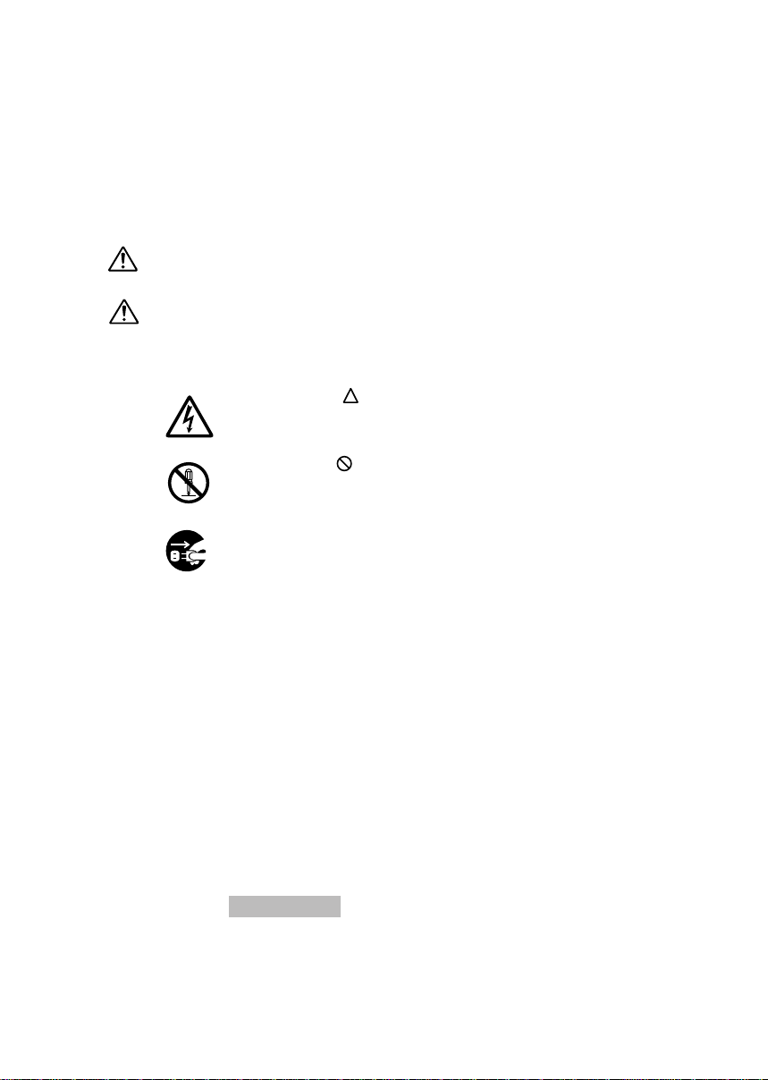
The following icons are also used with the above icon/word combinations to prevent personal injury
and/or property damage.
Indicates a hazardous situation that could result in fatal or serious wound
if the correct procedure is not applied.
Indicates a hazardous situation that could result in personal injury and/or
property damage if the correct procedure is not applied.
The icon that indicates the corresponding instruction is a warning.
The illustration displayed inside or beside the icon shows what the warning
actually means.
The icon that indicates the corresponding instruction is a banned action.
The illustration displayed inside or beside the icon shows what is actually
banned.
The icon ● that indicates the corresponding instruction is a command to
proceed. The illustration displayed inside or beside the icon shows what
to proceed.
● Representing keys and use thereof
In the text of the manual, keyboard keys are represented using only necessary characters as shown
below.
Example: [Ctrl] key, [Enter] key, and [→] key
When more than one key is to be pressed simultaneously, the keys are represented using “+”
between keys as shown below:
Example: [Ctrl] + [F3] and [Shift] + [↑]
● Representing buttons
Buttons displayed on the screen are enclosed in square brackets, [and], as shown below:
Example: [OK]
● Command entries
In the text of the manual, a command is represented as shown below:
diskcopy a: a:
↑↑
Page 6

A blank (shown with [↑]) between characters indicates that the [Space] key (long bar on the front
of the keyboard) is to be pressed once. Command names are represented in lowercase but may
be entered using uppercase letters.
● Conventions used in the text of the manual
The symbols used in the text of the manual have meanings as explained below:
Point
Help
Point indicates information necessary to run hardware or software.
Help indicates information explaining how to terminate an incorrect operation or
troubleshoot.
● Screen display examples
Screen displays provided in this manual are examples and may be different from those (including
file names) actually appearing on the display screen.
● Illustrations
Illustrations in this manual are an example using (mainly) the DESKPOWER 6000/SS
(CD-ROM drive-equipped model) and may be different from those actually appearing on your PC
screen depending on the model type and options installed.
● Referencing products
In this manual, products are described using abbreviations as listed below:
Windows Me refers to Microsoft® Millennium operating system.
Windows 98 refers to Microsoft® Windows® 98 operating system.
Windows 2000 refers to Microsoft® Windows® 2000 operating system.
Windows NT refers to Microsoft® Windows NT® Workstation operating system Version 4.0.
The terms “your PC,” “the PC,” “your PC main unit,” and “the PC main unit” refer to the DESKPOWER
8000.
Page 7
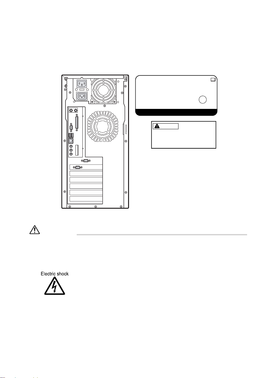
■ Warning and caution labels
FC
The PC bears warning and caution labels as shown below.
The warning and caution labels must not be removed or damaged.
WARNING
DESKPOWER
TN
MODEL FPC-T80000
P/N CP027008-01
100-120 (3.5A) / 200-240V (1.75A) 50/60Hz
LISTED
UL1950
U
L
®
7J61
MADE IN JAPAN
FUJITSU LIMITED
WARNING
Electric shock
To prevent electric shock,
switch off the PC and
connected peripherals and
unplug power cords from
respective outlets before
disassembling the unit and
installing a built-in option.
● 115 of voltage switch in the power supply corresponds to
100-120V.
● 230 of voltage switch in the power supply corresponds to
200-240V.
● Before mounting or dismounting an optional unit in/from your
PC, switch off the PC and all connected units and unplug all
power cords from respective outlets to prevent electric shock.
Page 8

Manual configuration
Chapter 1 Introduction
This chapter provides basic information on the PC, such as the names
and functions of individual parts, and also explains the basic operation
of the PC, such as turning the power on or off.
Chapter 2 Hardware
This chapter provides basic information on how to handle the
components installed (or can be installed) on the PC.
Chapter 3 Troubleshooting
This chapter explains how to respon to a problem occurring in the PC.
read wherever applicable.
Chapter 4 Technical Information
This chapter explains the specifications and other information relating
to this PC.
Page 9

Contents
Chapter 1 Introduction....................................................................... 1
1 Part Names and Functions ..............................................................2
Front of the PC unit .......................................................................................... 2
Back of the PC unit ..........................................................................................4
Inside the PC unit............................................................................................. 6
Motherboard..................................................................................................... 7
2 Keyboard ...........................................................................................8
Using the mouse ............................................................................................ 10
3 Mouse ..............................................................................................10
4 Installation.......................................................................................12
Installation area.............................................................................................. 12
Example of installation ................................................................................... 12
5 Connection......................................................................................13
Connecting the display, keyboard, mouse, and LAN cables .......................... 14
Connecting the power cable........................................................................... 16
6 Turning On the Power.....................................................................18
Notes on power-on......................................................................................... 18
Turning on the power...................................................................................... 18
7 Turning Off the Power ....................................................................20
Notes on power-off......................................................................................... 20
Turning off the power...................................................................................... 20
8 Resetting .........................................................................................21
Resetting the PC ............................................................................................ 21
9 CDs...................................................................................................23
Notes on handling .......................................................................................... 23
Inserting or Removing CD.............................................................................. 24
10 Floppy Disk .....................................................................................25
Notes on handling .......................................................................................... 25
Inserting or removing a floppy disk ................................................................25
Chapter 2 Har dware ......................................................................... 27
1 Before Installing a Peripheral Device............................................28
What are peripheral devices? ........................................................................ 28
Notes on handling .......................................................................................... 28
Location for installation ..................................................................................30
File bay options .............................................................................................. 31
2 Removing the Cover .......................................................................34
Removing the side and upper covers, and front panel ................................... 34
Page 10

3 Increasing the Memory Capacity...................................................38
Location of memory modules ......................................................................... 39
Applicable memory modules .......................................................................... 39
Installing/removing memory modules............................................................. 40
4 Installing Expansion Cards............................................................43
Applicable expansion cards............................................................................44
Installing an expansion card........................................................................... 44
5 Installing an Internal Hard Disk .....................................................47
Notes on handling the hard disk..................................................................... 47
Installing a disk in the internal hard disk bay.................................................. 47
Installing a disk in the front access bay.......................................................... 50
6 Installing Other Devices.................................................................51
Installing front access bay options ................................................................. 51
Chapter 3 Troubleshooting.............................................................. 57
1 Problems .........................................................................................58
Chapter 4 Technical Information..................................................... 61
1 Maintenance of the Hardware........................................................62
Maintenance of the keyboard......................................................................... 62
Maintenance of CDs....................................................................................... 62
Maintenance of the mouse............................................................................. 63
Cleaning of the floppy disk drive .................................................................... 64
2 Preventing Television or Radio Interference................................65
3 Security of the Case .......................................................................66
Specifications of PC unit ................................................................................ 67
4 Hardware Specifications .................................................................67
LAN adapter specifications ............................................................................ 69
Sound specifications ...................................................................................... 69
Graphical specifications ................................................................................. 69
Connector specifications ................................................................................ 70
5 Other Precautions...........................................................................73
Disposal ......................................................................................................... 73
Power-saving function (Windows 2000 models)............................................. 73
USB (Windows 2000 models) ........................................................................ 73
When using USB devices............................................................................... 73
USB hub (Windows 2000 models) ................................................................. 74
Addition of LAN adapter ................................................................................. 74
Precautions on using display ......................................................................... 74
Replacement of display.................................................................................. 74
Making a sound when starting and exiting Windows (for Windows NT
models).......................................................................................................... 75
ACPI standby mode (Windows 2000 models)................................................ 75
Index ......................................................................................................76
Page 11
1
Chapter 1 Introduction
This chapter provides basic information on the PC, such as the names and
functions of individual parts, and also explains the basic operation of the PC, such
as turning the power on or off.
Page 12
1 Part Names and Functions
This section explains the names and functions of the parts of the PC unit and the motherboard.
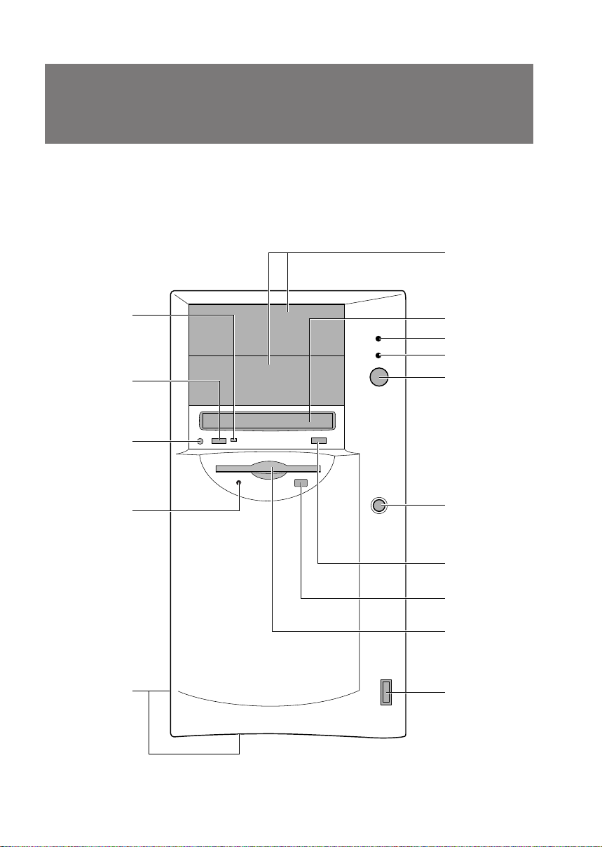
■ Front of the PC unit
6
1
2
3
4
5
7
8
9
10
11
12
13
14
15
2
Page 13

1 Busy lamp
This lamp lights up while data is read from a CD-ROM or music CD is played.
2 Headphone volume (only for music CDs)
Use this control to adjust the volume of headphones.
3 Headphone jack (only for music CDs)
When listening to a music CD with a headphone, plug it to this jack.
4 Floppy disk access lamp
This lamp lights up while the floppy disk is accessed.
5 Ventholes (on the side panel and the bottom of the front panel)
These ventholes take air in for cooling inside.
6 Front access bay
Connect optional devices, such as an internal hard disk and a magneto-optical disk drive).
7 CD-ROM drive
Insert a CD-ROM into this drive to read data or programs, or insert a music CD for playback.
8 Hard disk access lamp
This lamp lights up while the hard disk is accessed.
9 Power lamp
This lamp lights up in green when the PC is on.
This lamp lights up in orange in the standby (power-saving) mode.
10 Power switch
Press this switch to turn on the PC or set the system to the standby (power-saving) mode.
11 Reset switch
Press this switch to delete data from the memory to re-load programs including OS.
12 Eject button
Press this button to insert or remove a CD-ROM.
13 Floppy disk eject button
Press this button to remove a floppy disk from the floppy disk drive.
Do not press this button when the floppy disk access lamp is on.
14 Floppy disk drive
Writes data to or read data from a floppy disk.
15 USB connector
Connect a USB peripheral device.
3
Page 14
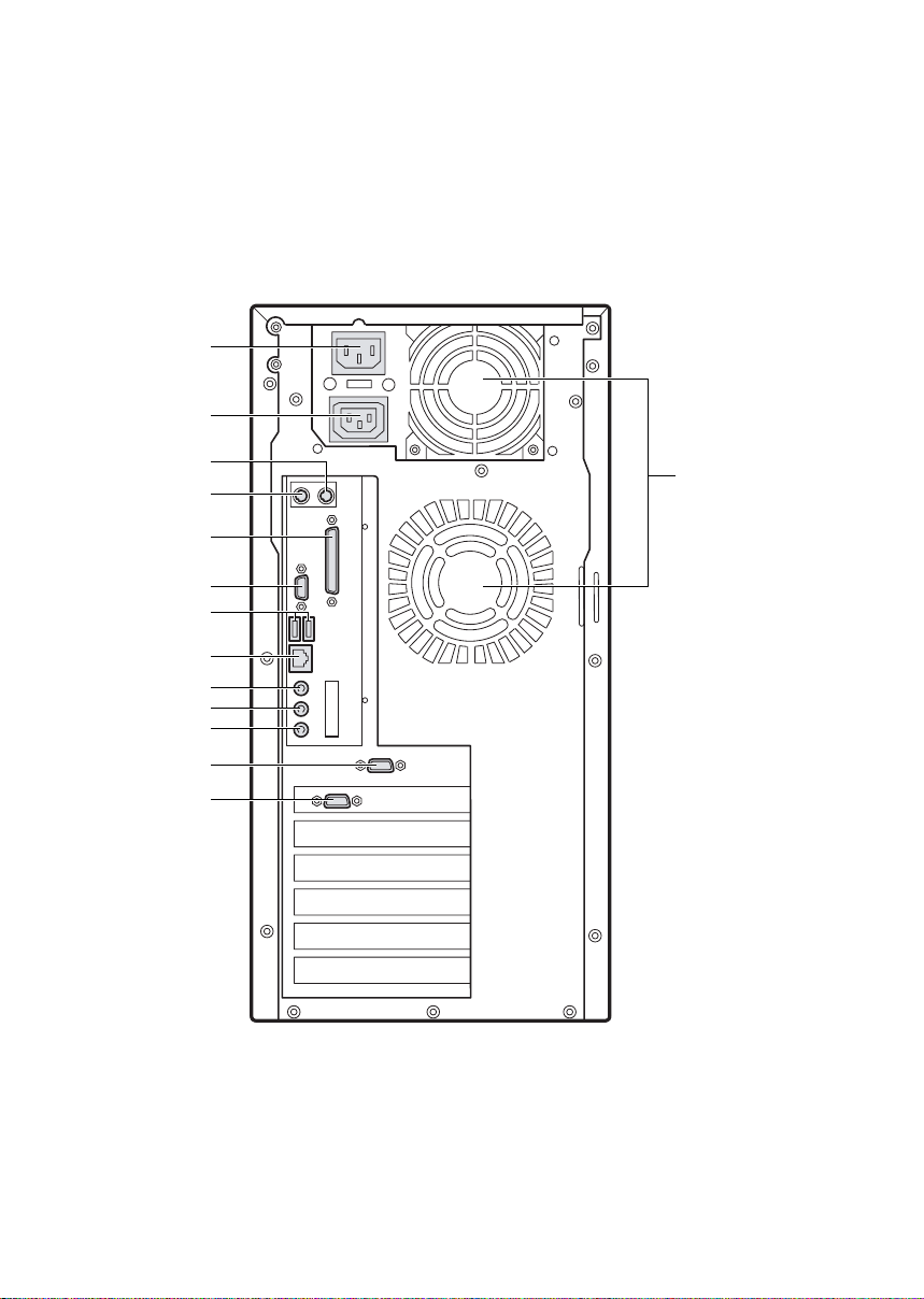
■ Back of the PC unit
1
2
10
11
12
13
3
4
5
6
7
8
9
14
4
Page 15

1 Inlet
Connect the power cable.
2 Outlet
Connect the power cable of the display to this outlet.
3 Mouse connector ( : MOUSE)
Connect a mouse.
4 Keyboard connector ( : KEYBOARD)
Connect the keyboard.
5 Parallel connector (PRINTER)
Connect a printer cable to this connector.
6 Serial connector (RS-232C (1))
Connect a cable for an RS-232C-based device (e.g. modem).
7 USB connector
Connect a USB peripheral device.
8 LAN connector
Connect a LAN cable.
9 LINE OUT terminal
A terminal for sound output. Connect the input terminal of audio equipment to this terminal.
When connecting speakers, use those with a built-in amplifier.
10 LINE IN terminal
A terminal for sound input. Connect the output terminal of audio equipment to this terminal.
11 MIC IN terminal
Plug a capacitor microphone to this jack.
12 Serial connector (RS-232C (2))
Connect a cable for an RS-232 C-based device (e.g. modem).
13 CRT connector
Connect the cable of an analog RGB display.
14 Venthole
An opening provided to let heat go out of the PC.
5
Page 16
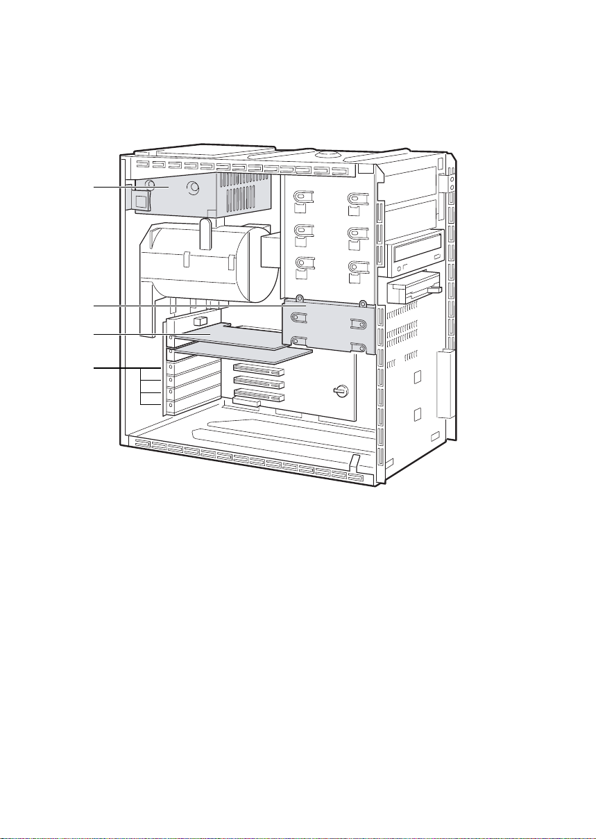
■ Inside the PC unit
1
2
3
4
1 Power supply unit
2 Internal hard disk bay
Install an IDE-compliant internal hard disk. You can replace the standard internal hard disk by a
large-capacity one.
3 Display card
4 Expansion card slots
Insert optional expansion cards to these slots.
This slot accommodates a PCI card.
6
Page 17
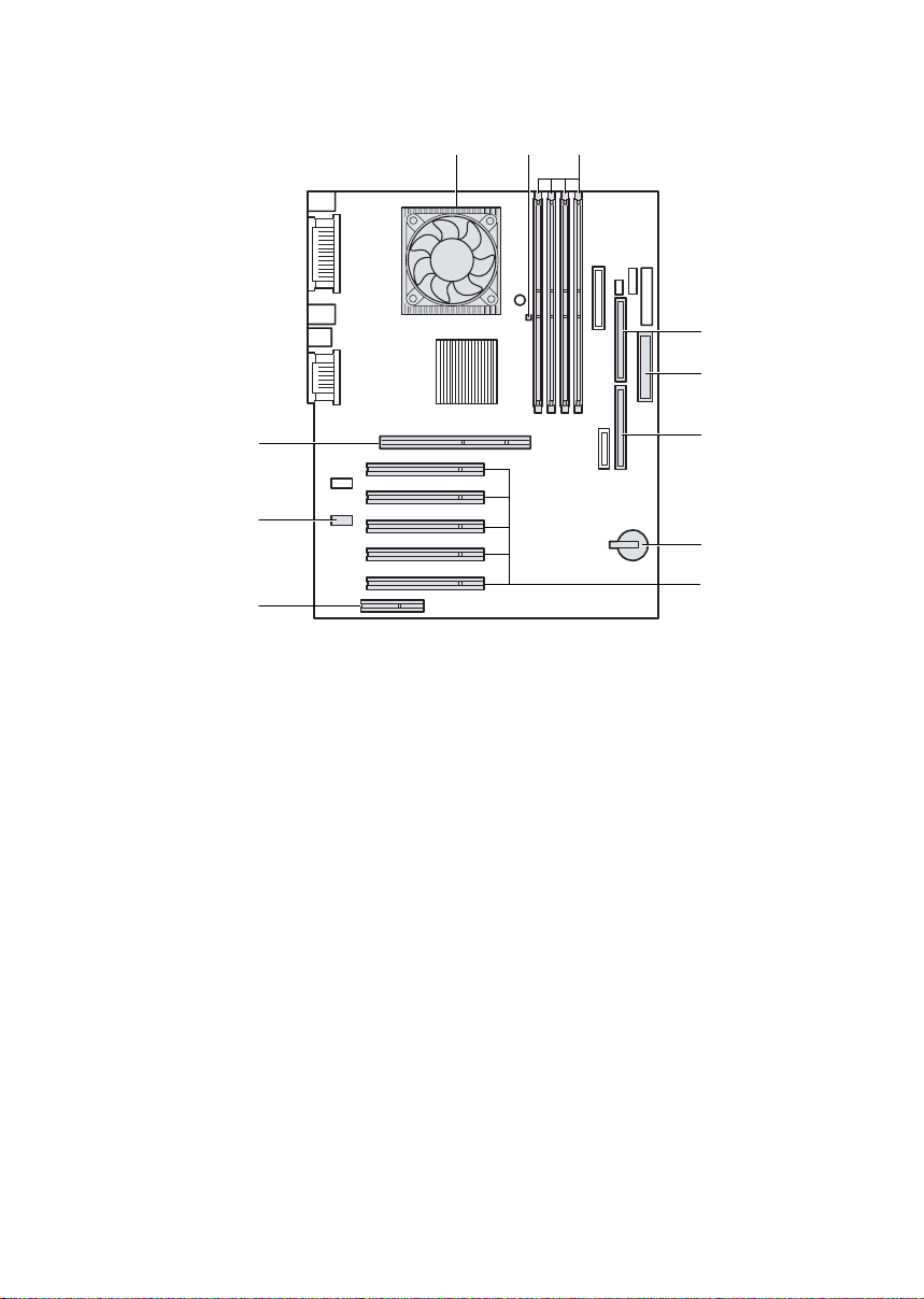
■ Motherboard
123
4
5
11
10
9
1 CPU
2 Memory power LED
Lights up when memory power is on.
3 Memory slots
Memory modules are inserted into these slots. These slots are marked RIMM1-RIMM4 in this
order from the left in the figure above.
4 Secondary IDE connector
Connect a CD-ROM drive cable to this connector.
5 Floppy disk drive connector
Connect a floppy disk drive cable to this connector.
6 Primary IDE connector
Connect a cable of the hard disk running OS.
7 Internal battery
This battery is used to save setup values of the PC. The life is about 5 years under normal use.
8 PCI slots
Insert PCI cards. PCI slots, 1 to 5 are arranged in this order from the top in the figure above.
9 CNR connector
Not available with your PC.
10 CD IN connector (black)
Connect an AUDIO cable of CD-ROM drive to this connector.
11 AGP connector
Connect a display card.
6
7
8
7
Page 18
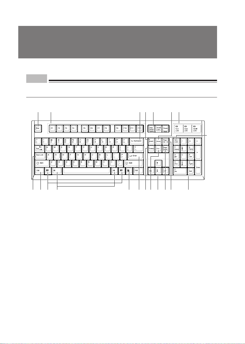
2 Keyboard
This section explains the functions of the keys on the keyboard.
Point
• The functions assigned to the keys vary depending on an OS or program running on your PC.
For details, refer to the manual for the OS or program.
1 235467
8 9 10 11 12 1314 15 16 17 18 19
20
1 Esc (escape) key
Press the Esc key to terminate the execution of software.
2 F (function) keys
These F keys are assigned specific functions for each application.
3 Backspace key
Press the Backspace key to move the cursor to the left while deleting characters.
4 Insert key
Press the Insert key to switch between character insert mode and overwrite mode.
5 Print Screen key
Press the Print Screen key to capture a screenshot in the clipboard.
6 Home key
Press the Home key to move the cursor all at once to the beginning of the current line or text.
7 Indicators
Each of these indicators turns on when the corresponding key (or a combination of keys) ([Num
Lock], [Caps Lock], or [Scroll Lock]) is pressed to enable the key function. When the key is pressed
again, the indicator turns off and the key function is disabled.
8
Page 19

8 Caps Lock/Alphanumeric key
Use the Caps Lock/Alphanumeric key to type alphabetical characters.
Press [Caps Lock] to switch between uppercase and lowercase.
9 Ctrl (control) key
Use the Ctrl key in combination with another key. Its function varies with each application.
10 Windows key
Press the Windows key to display the “Start” menu.
11 Alt key
Use the Alt key in combination with another key. Its function varies with each application.
12 Application key
This key has the same function as clicking the right mouse button.
Press this key to display the shortcut menu of the selected item.
13 Enter key
The Enter key is also referred to as the Return or Line Feed key.
Press this key to perform line feed or execute a command.
14 Delete key
Press the Delete key to delete a character. Pressing the Delete key together with the [Ctrl] and
[Alt] keys resets the PC.
15 End key
Press the End key to move the cursor all at once to the end of the current line or text.
16 Cursor keys
Press each of these keys to move the cursor in the desired direction.
17 Page Down key
Press the Page Down key to display the next page (screen).
18 Page Up key
Press the Page Up key to display the previous page (screen).
19 Ten-key pad
When the “Num Lock” indicator is on, numerals can be entered from the Ten-key pad.
When the “Num Lock” indicator is off, the function indicated on the lower part of each keytop is
enabled.
20 Num Lock (numerical lock) key
Press the Num Lock key to change the Ten-key pad functions.
Point
• To tilt the keyboard, pull up the tilt foot on the both sides of the underside of the keyboard.
Tilt foot
9
Page 20
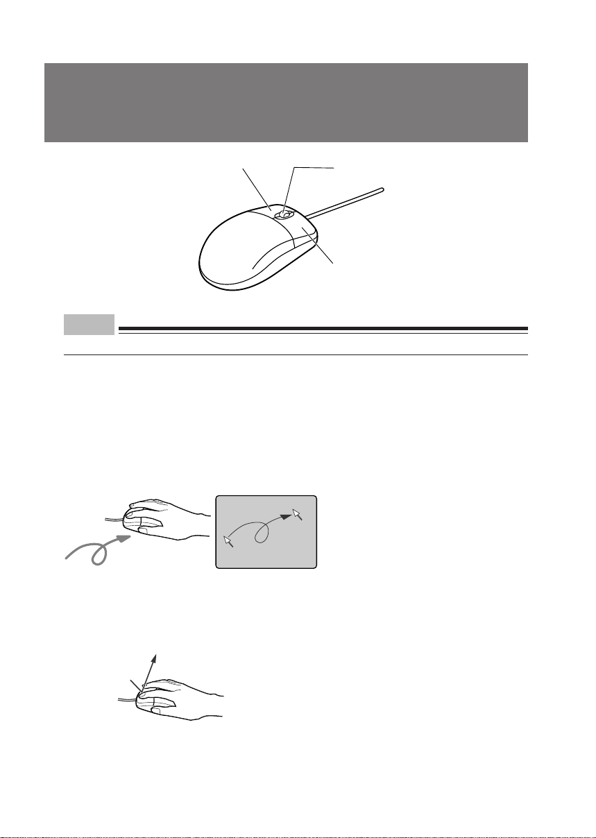
3 Mouse
Point
• Clean the mouse regularly.
Left button
Scroll button
Right button
■ Using the mouse
● Moving the mouse
Lightly hold the mouse and place your index and middle fingers on the left and right buttons on
the mouse. Slide and move the mouse over a plane surface, such as a desktop. As you move the
mouse, an arrow (called the mouse pointer) moves in the same way on the screen. Move the
mouse and see how the mouse pointer moves.
● Using the mouse buttons
Clicking
Click
Clicking is a series of action of pressing and releasing the left mouse button once.
Clicking the right mouse button is particularly called “right-clicking.”
10
Page 21
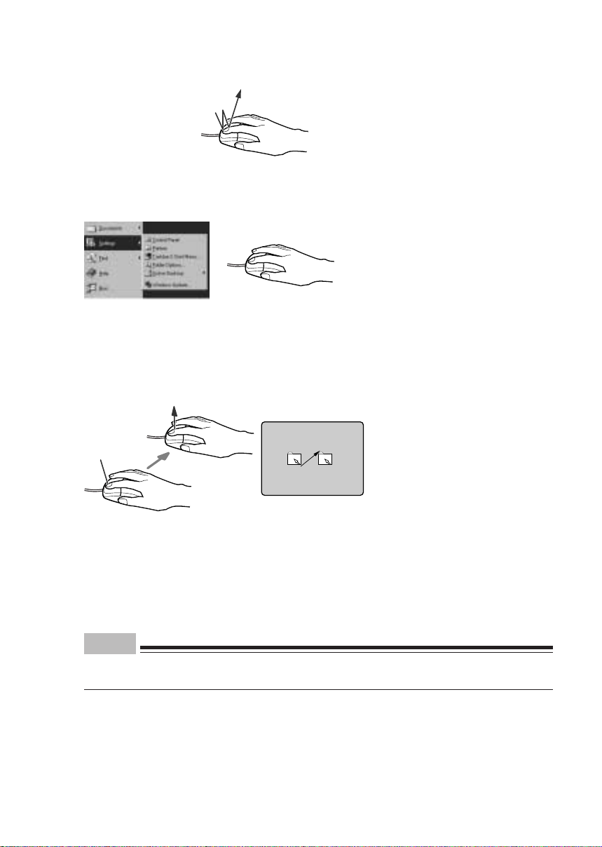
Double-clicking
Click-Click
Double-clicking is a series of action of pressing and releasing the left mouse button twice.
Pointing
Pointing is an action of moving the mouse pointer to an object or item such as a menu. If the pointed
menu item has subordinate items ( is displayed at the right end), the items are displayed.
Dragging
Release
Press
Dragging is an action of moving the mouse while holding down the left mouse button and release
the button at a desired position.
Scrolling
• The scroll wheel is used to scroll the screen. This wheel can also be used as the third button.
• The scrolling function can be used on applications that support a scroll wheel.
Point
• The button operation explained above is applicable when “right-handed use” is selected in
the “Mouse Properties” dialog box.
11
Page 22
4 Installation
This section explains how to install your PC and also provides note on using the PC.
■ Installation area
Do not install your PC in the following areas.
• Areas that are humid, dusty, or subjected to oil mist.
• Poorly ventilated areas
• Areas where fire is used
• Bathrooms and other areas where water may splash
• Areas exposed to direct sunlight or near a heater and other areas with high temperatures
• Areas with temperatures below 10°C
• Areas where you may trip on a cable.
• Areas subjected to a strong magnetic field, such as near a television or speaker.
• Unstable areas with violent vibration or on a slanted surface
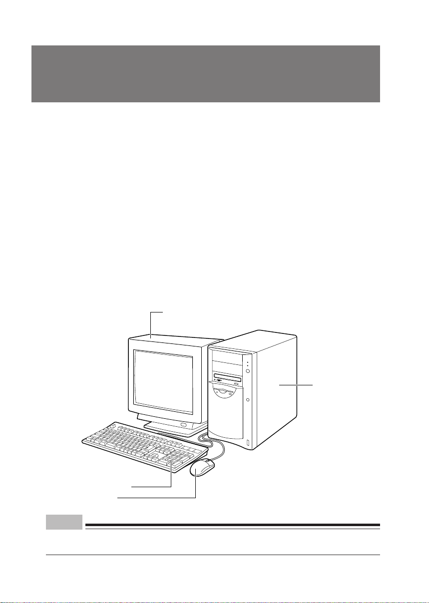
■ Example of installation
Install your PC as shown in the figures below.
CRT display
PC unit
Keyboard
Mouse
Point
• When installing your PC, be sure not to block the ventholes on the sides, bottom, and back of
the PC unit.
12
Page 23
5 Connection
Connect the display, keyboard, and power cables to your PC unit.
CAUTION
● Before turning on the power, ground devices whenever necessary.
Otherwise, an electric shock may occur.
Do not connect a grounding wire to gas piping.
Otherwise, a fire may occur.
● Before connecting or disconnecting the display, keyboard, mouse, LAN
cable, or power cable, turn off the PC and all device power connected to it,
and unplug them.
Otherwise, an electric shock may occur.
● Use a Fujitsu-supplied display, keyboard, and mouse.
Otherwise, an electric shock, a fire or fault may occur.
WARNING
● Connect the cables correctly.
An incorrect connection could result in a fault in the PC unit or peripheral
devices.
● For a device having a service outlet, connect only devices specified in the
manual to the outlet.
Otherwise, a fire or fault may occur.
● When assessing the PC board, touch the specified areas only.
Otherwise, personal injury or faults may occur.
13
Page 24
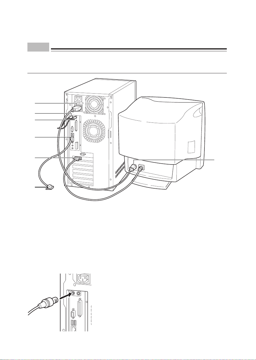
■ Connecting the display, keyboard, mouse, and LAN cables
Point
• This section explains how to connect your display and PC unit so that the display is powered
by the PC unit. In this case, the power cable attached to the display is not used.
• Use an optional twisted pair LAN cable if required.
1
3
4
6
5
7
1 Connect the power cable to the outlet.
Connect the power cord one end of the power cable (for CRT), which is supplied with the PC unit,
to the outlet of the PC unit.
2 Connect the power cable to the display.
Connect the power cord the other end of the power cable (for CRT), which is supplied with the PC
unit, to the inlet on the back of the display.
3 Connect the keyboard.
With the mark on the connector of the keyboard cable facing right, plug the keyboard connector
to the back of the PC unit as indicated by the keyboard label color on the back.
2
14
Page 25
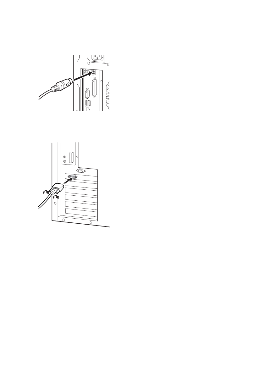
4 Connect the mouse.
With the mark on the connector of the mouse cable facing right, plug the mouse connector to the
back of the PC unit as indicated by the mouse label color on the back.
5 Connect the display cable to the PC unit.
Connect the display cable connector to the display connector on the back of the PC unit and tighten
the cable connector screws.
If you have not set up Windows, proceed to “Connecting the power cable”.
Connecting a LAN cable before making Windows setup may result in an error during setup.
The LAN cable must, therefore, be connected after you have completed the setup.
6 Connect the LAN cable.
Connect the connector on the other end of the twisted pair cable to the LAN connector on the
back of the PC unit.
7 Connect the LAN cable.
Connect the connector on one end of the twisted pair cable (to be purchased separately) to a
network connector such as a hub unit.
15
Page 26
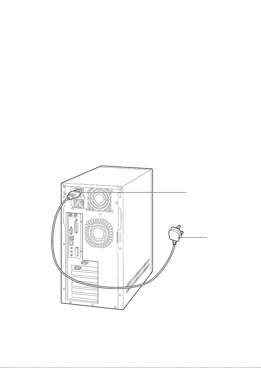
■ Connecting the power cable
After connecting the display and other peripheral devices, connect the power cable of the PC
unit. Note the following:
• Do not connect or disconnect the plug with wet hands.
• Do not damage or modify the power cable.
• Do not compress, pull, bend, twist, or heat the power cable.
• Do not use the power cable if it or the plug is damaged or connection to the outlet is not secure.
• If there is dust on the electrodes of the plug or slots in the outlet, wipe it off with a dry cloth.
• Connect the power cable to a 230V AC outlet.
• Do not include the power cable in a star-burst connection. Do not entangle the power cable with
the keyboard or mouse cable.
• In the event of lightning, disconnect the power cable from the outlet.
• When connecting the power cable to a two-pin outlet, use the adapter plug supplied with the
power cable to connect the grounding wire.
• When disconnecting the power cable, pull on the plug (not the cable).
• Fully insert the cable plug in the outlet.
• If the PC is not to be used for an extended time, disconnect the power cable from the outlet.
1
16
2
Page 27
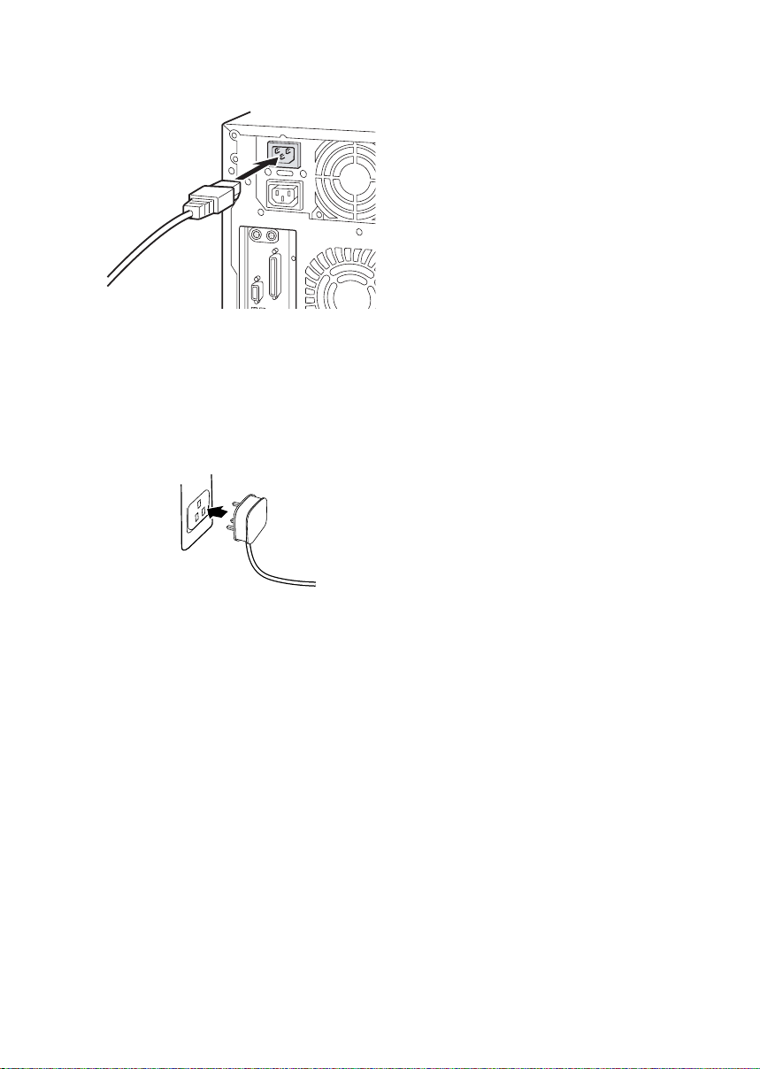
1 Connect the power cable plug to the inlet on the back of the PC unit.
2 Connect the power cable plug to an outlet.
Connect the plug on the other end of the power cable to an outlet. When connecting the power
cable to a two-pin outlet, attach the adapter plug supplied with the power cable to the cable plug
and then connect to the outlet.
Connect the grounding wire, extending from the adapter plug, to the grounding terminal and secure
it by tightening the screw.
17
Page 28

6 Turning On the Power
This section explains how to turn on the power.
■ Notes on power-on
• If nothing is displayed on the screen, check if the display cable is properly connected.
• In the case that the screen is not displayed in the center, adjust it using the display.
• When the power-on self-test (POST) detects an error, an error message is displayed.
• When the power cable of the display is connected to the PC, the display power is turned on or
off automatically when the PC power is turned on or off. Therefore, once the power switch on
the display is pressed, subsequent operation is not necessary.
• The display power is automatically turned on each time the power switch on the PC is pressed
as in Step 2 below. However, it is required to power on peripheral devices other than the display
before powering on your PC.
• When the display power is not automatically turned on with the PC power, you are required to
turn on it before turning on the PC.
• To turn off the PC power just after turning it on, wait until the OS starts and turn it off following
the instructions described in “Turning Off the Power”.
■ Turning on the power
WARNING
● Do not carry or subject the PC to shock or vibration while the PC is on.
Otherwise, a fault may occur.
1 Press the power switches on the display and other peripheral devices.
At this time, nothing is displayed on the screen.
18
Page 29

2 Press the power switch on the PC.
The power lamps on the display and PC light up.
After the PC is turned on, the “FUJITSU” logo appears, during which power-on self-test is being
performed, then the system starts up.
19
Page 30

7 Turning Off the Power
This section explains how to turn off the power.
■ Notes on power-off
• Before turning off the power, terminate all work and save data.
• Before turning off the power, confirm that the floppy disk and the hard disk access lamps are off.
If the power is turned off while the lamps are on, data being processed may not be saved or data
on the floppy disk or hard disk may be damaged.
• To turn off your PC and back on again, wait for at least 10 seconds.
■ Turning off the power
● For Windows Me or 98 model:
1 Click the [Start] button, then click [Shut down].
The [Shut down Windows] dialog box appears.
2 Click [Shut Down] from the pull down item.
The power is automatically turned off.
● For Windows NT model:
1 Click the [Start] button, then click [Shut down].
The [Shut down Windows] dialog box appears.
2 Click [Shut Down the Computer], then click [Yes].
Press the power button to turn it off.
● For Windows 2000
1 Click the [Start] button, then click [Shut down].
The [Shut Down Windows] dialog box appears.
2 Select [Shutdown] and click [OK].
The power is automatically turned off.
Point
• The power can also be turned off in the following procedure.
1 Press the [Ctrl] + [Alt] + [Delete] keys.
The [Windows security] dialog box appears.
2 Click [Shutdown].
The [Shutdown Computer ] dialog box appears.
3 Select [Shutdown] and click [OK].
The power is automatically turned off.
20
Page 31

8 Resetting
After software installation or when software hangs, the PC must be reset (restarted).
This section explains how to reset (restart) the PC.
Point
• Resetting (restarting) the PC clears data in the memory. Save data before resetting (restarting)
the PC.
■ Resetting the PC
● For Windows Me or 98 model
1 Click the [Start] button, then click [Shut down].
The [Shut Down Windows] dialog box appears.
2 Click [Restart] from the pull down item.
The system is reset (restarted).
● For Windows NT model
1 Click the [Start] button, then click [Shut down].
The [Shut Down Windows] dialog box appears.
2 Click [Restart the computer], then click [Yes].
The PC is reset (restarted).
Point
• The PC can also be reset (restarted) in the following procedure.
1 Press the [Ctrl] + [Alt] + [Delete] keys.
The [Windows NT security] dialog box appears.
2 Click [Shutdown].
The [Shutdown Computer ] dialog box appears.
3 Click [Shutdown and Restart], then click [OK].
The PC is reset (restarted).
21
Page 32

● For Windows 2000
1 Click the [Start] button, then click [Shut down].
The [Shut Down Windows] dialog box appears.
2 Click the [Restart] button, then click [OK].
The PC is reset (restarted).
Point
• The PC can also be reset (restarted) in the following procedure.
1 Press the [Ctrl] + [Alt] + [Delete] keys.
The [Windows security] dialog box appears.
2 Click [Shutdown].
The [Shut Down Windows] dialog box appears.
● Hard resetting
A hard reset is an action to reset your PC using the Reset switch. It is used to initialize peripheral
devices, such as optional cards, hard disk drive, and floppy disk drive.
1 To perform a hard reset, press the Reset switch on your PC about 1 second and then
release it.
Reset switch
Point
• Hard reset your PC if it hangs for some reason and cannot be reset on the OS.
• Avoid turning off your PC at once when it hangs, of the hard disk may be damaged.
22
Page 33

9 CDs
This section explains how to handle, insert, and remove CDs.
■ Notes on handling
To prevent faults, note the following when handling CDs.
● Notes on handling CDs
• Do not use a ball-point pen or pencil on the label (printed side). Do not affix a label.
• Do not touch or damage the data side.
• Do not bend or compress them.
• If the CD gets dirty or wet, wipe it with a dry soft cloth from the center to the edge. Do not use a
cleaner.
• Keep them dry.
• Do not place them in an extreme temperature environment.
• Do not place them in a humid and dusty environment.
● Notes on using the drive
• Do not use CDs that do not meet the requirements in “Notes on handling CDs,” or those warped,
damaged, or cracked. Otherwise, a fault may occur. Faults caused by the use of a defective CD
shall not be covered by the warranty.
• This PC can use circular CDs only. Do not use odd-shaped CDs. Otherwise, a fault may occur.
Faults caused by the use of an odd-shaped CD shall not be covered by the warranty.
• Use of a commercially available CD-ROM cleaning disc may place dust on the lens. Do not use
a CD-ROM cleaning disk.
Point
• CD-ROM is a compact disc (CD) that stores PC information (such as characters) rather than
music. ROM stands for Read Only Memory. This PC can read data from CD-ROMs but cannot
write data, except when CD-R/RW is selected as a custom-made option.
• This PC can use CDs having any of the following marks. Do not use CDs without a mark.
Otherwise, a fault may occur.
An additional application may be necessary to use particular types of CDs.
* ASTERISKED CDS CAN ONLY BE USED ON CD-R/RW DRIVES TO WRITE DATA.
23
Page 34

■ Inserting or Removing CD
● Inserting a CD
1 Press the eject button.
This ejects the tray to mount a CD.
Eject button
2 With the label side of the CD facing upward, put the CD in the center of the tray.
3 Press the eject button.
The tray enters the unit to load the CD.
Point
• The BUSY lamp lights up when the CD is loaded. Proceed to the following operation after making
sure that the BUSY lamp turns off.
● Removing the CD
Confirm that the Busy lamp is off, then press the Eject button to remove the CD.
24
Page 35

10 Floppy Disk
Floppy disks are used to store data and programs. This section explains how to handle, insert,
and remove floppy disks.
■ Notes on handling
To prevent faults, note the following when handling floppy disks.
• Keep them dry.
• Do not open the shutter to touch the disk inside.
• Do not bend or compress them.
• Keep them away from magnetism.
• Do not drop them.
• Do not place them in an extreme temperature environment.
• Do not place them in a humid and dusty environment.
• Do not overlay too many labels (causes clogging in the drive).
• Keep the hard disk free from condensation or moisture.
■ Inserting or removing a floppy disk
Point
• Use DOS/V formatted floppy disks. Operation with other types of floppy disks is not guaranteed.
● Inserting a floppy disk
With the label side of the floppy disk facing upward, insert the floppy disk (from the shutter side)
into the drive.
The floppy disk eject button pops out with a click.
Floppy disk eject button
Shutter
Label
25
Page 36

● Removing the floppy disk
1 Confirm that the floppy disk access lamp is off.
Floppy disk access lamp
Point
• Do not press the floppy disk eject button while the floppy disk access lamp is on. The data on
the floppy disk may be damaged.
2 Press the floppy disk eject button.
The floppy disk is ejected.
26
Page 37

2
Chapter 2 Hardware
This chapter provides basic information on how to handle the components
installed (or can be installed) on the PC.
27
Page 38

1 Before Installing a Peripheral
Device
This section gives an outline of peripheral devices.
■ What are peripheral devices?
This PC can accommodate various peripheral devices to expand its functions.
Some peripheral devices may not be used on your PC.
CAUTION
● Use only peripheral devices recommended by Fujitsu.
Otherwise, an electric shock, a fire or fault may occur.
WARNING
● When installing or removing a peripheral device, do not remove screws
other than those specified in the manual.
Otherwise, personal injury or faults may occur.
● Read this manual carefully to ensure correct cable connections.
An incorrect connection could result in a fault in the PC or peripheral
devices.
28
Page 39

■ Notes on handling
When installing a peripheral device, note the following.
• Whenever possible, use peripheral devices supplied by Fujitsu.
Malfunction or damage caused by the use of a third-party product instead of the Fujitsu device
shall not be covered by the warranty.
• Before using a peripheral device in a category for which Fujitsu does not supply genuine products,
contact the third-party manufacturer to ask whether the device is compatible with the PC.
• Have you finished Windows setup?
Installing a peripheral device on the PC before setup may cause the setup program to fail.
• Install one peripheral device at a time.
Installing more than one peripheral devices at a time may cause driver installation to fail.
• Turn off the PC and connected devices.
For safety, be sure to unplug the PC and connected devices. Even if the PC is turned off, an
electric current flows in the PC unit.
• Do not start work immediately after turning off the power.
Components inside the PC may be still hot. After turning off the power and unplugging the PC,
wait for about 10 minutes before starting work.
• Do not disassemble the power supply unit.
The power supply unit is a box-shaped component on the back inside the PC.
• Be careful with the cables and components inside.
Do not damage or modify them.
• Be careful of static electricity.
PC boards and electronic parts of internal peripheral devices are exposed. They may be damaged
by static electricity generated on your body. Before handling these parts, touch a large metallic
object to discharge static electricity.
• Do not touch PC board surface, soldered parts or connectors.
Hold PC boards by the brackets or edges.
• Power supply for peripheral devices
Typical peripheral devices should be turned on before turning on the PC, however, some should
be turned on after the PC. See the manual for the peripheral device.
• Use ACPI-compatible devices (for Windows 2000).
Since the PC is controlled as per ACPI (one of the power supply control standards for power
saving), peripheral devices must conform to the ACPI standard.
• The use of a peripheral device not conforming to the ACPI standard may cause malfunction of
the PC or device. Contact the device manufacturer to ask if your device supports ACPI.
Use an appropriate screwdriver.
• You must use a Phillips screwdriver to remove slot covers and brackets from the PC.
Use a screwdriver of an appropriate size not to damage screw heads.
29
Page 40

■ Location for installation
12
4
1 Memory slots
Memory modules are inserted into these slots.
Increasing the memory capacity increases the amount of data that the system can read at one
access,thereby improving the processing capability of the PC.
2 Front access bay
Attach an optional internal SCSI device (such as magneto-optical disk drive), or IDE device (such
as a hard disk) as necessary.
Unlike external devices, front access bay options receive power from the PC unit, and therefore
require no outlet. They also save space.
3 Internal hard disk bay
Connect an (IDE-compliant) internal hard disk.
4 Expansion card slots
Attach expansion cards. For instance, a SCSI card allows you to install a SCSI-compliant hard
disk or magneto-optical disk drive.
3
30
Page 41

■ File bay options
This section explains how to install file bay options, such as internal hard disks, magneto-optical
disk drives, and floppy disk drives. Unlike external devices, file bay options receive power from
the PC unit, and therefore require no outlet. They also save space.
CAUTION
● Before installing or removing a file bay option, turn off the PC and all
devices connected to it, and unplug them.
Otherwise, an electric shock may occur.
WARNING
● Use Fujitsu-supplied file bay options.
Otherwise, an electric shock, a fire or fault may occur.
● When installing or removing file bay options, do not remove screws other
than those specified.
Otherwise, personal injury or faults may occur.
● When assessing the PC board, touch the specified areas only.
Otherwise, personal injury or faults may occur.
31
Page 42

● Notes on installation
• If you want to install file bay options to your PC, set up Windows and then turn off the PC before
doing so.
• An internal hard disk can be set to Ultra DMA/100. With the DMA initialization, channel 0 is enabled
and channel 1 is disabled for a Windows NT model, while the standard hard disk is set to Ultra
DMA mode and the CD-ROM drive is set to PIO mode for a Windows Me/98/2000 model.
Refer to the manual for your hard disk to check whether it supports Ultra DMA.
When installing a hard disk unit that does not support Ultra DMA, be sure to set DMA to OFF or
disable it. If it is used with DMA set to ON or enabled, the unit may not work properly and may
destroy data.
• To operate an internal hard disk that supports Ultra DMA/100 under this standard, attach it to
the primary IDE. If attached to the secondary IDE, it operates under Ultra DMA/33, not under
Ultra DMA/100.
• Only one ATAPI-compliant magneto-optical disk drive can be installed on the PC. When installing
a drive, connect it to the secondary IDE.
● Master and slave
On standard models
This PC can accommodate up to four IDE-compliant devices. Install the first and second devices
to the master and slave of the primary IDE. Install the remaining two (third and fourth) devices to
the master and slave of the secondary IDE.
This master and slave setting depends on the connection between the internal IDE devices and
flat cables (this configuration is referred to as Cable-Select). Connecting the master connector of
a flat cable to an IDE device makes the device configured as a master, while connecting the slave
connector to a IDE device makes the device configured as a slave.
To enable Cable-Select, set the jumper switch of the internal IDE device to Cable-Select.
When connecting an internal IDE device that does not support Cable-Select to Master, configure
the device as a master. When connecting it to Slave, configure it as a slave.
32
Page 43

Third (master)
Fourth (slave)
*1
*2
Secondary IDE
Primary IDE
Front side
First (master) (hard
disk pre-installed)
Second (slave)
*1: CD-ROM drive pre-installed. When a magneto-optical disk is selected as a custom-made option, however, a
magneto-optical disk drive is installed.
*2: CD-ROM drive preinstalled when a magneto-optical disk is selected as a custom-made option.
*3: The internal hard disk bay accepts a hard disk only.
*4: Installed to the 5" front access bay when the front access unit for HDD is selected as a custom-made option.
<Primary IDE cable (80 pins)>
SLAVE MASTER
Pin 1 Pink line
Blue connector
To the
motherboard
Connect the option
here to configure it
as the master.
Connect the option
here to configure it
as a slave.
Pin 1 Red line
*4
*3
<Secondary IDE cable (40 pins)>
Point
SLAVE MASTER
• For this PC, the number of pins in a cable differs between those connected to the primary and
secondary IDEs. Use a 80-pin cable for connection to the primary IDE and a 40-pin one for
connection to the secondary IDE.
• By default, the pre-installed internal IDE device is configured to Cable-Select.
• Be sure to connect the hard disk that runs OS to the primary IDE connector as a master. If it is
connected as a slave or to the secondary IDE connector, OS may not run.
• For combination of the “master” and “slave” of the secondary IDE, refer to “Installing front access
bay options”.
33
Page 44

2 Removing the Cover
■ Removing the side and upper covers, and front panel
When mounting an internal option, remove the side cover so that the inside can be seen. When
mounting a front access bay option, remove the upper cover and front panel as well. Remove the
cover and panel as follows:
1 Turn off the PC and all devices connected to it, and unplug them.
2 Remove three right-hand three screws from the back of the PC unit.
34
Page 45

3 Remove the side cover.
Slide the PC cover toward the back (arrow in the illustration-1).
Raise the cover to remove it (arrow in the illustration-2).
2
1
4 Remove the bracket.
Remove one screw to remove the bracket.
Bracket
35
Page 46

5 Remove three left-hand three screws from the back of the PC unit.
6 Remove the upper cover.
Slide the PC cover toward the back (arrow in the illustration-1).
Raise the cover to remove it (arrow in the illustration-2).
2
36
1
Page 47

7 Remove two screws from the upper area of the front panel.
8 Remove the front panel.
Tilt the front panel toward you before pulling it up.
Point
• Remove the upper cover and front panel as necessary.
• Reinstall them in the reverse order.
37
Page 48

3 Increasing the Memory Capacity
This section explains how to remove or install memory modules. Increasing the memory capacity
increases the amount of data that the system can read at one access, thereby improving the
processing capability of the PC.
Point
• If you want to install a memory module soon after you purchase the PC, set up Windows, turn
off the PC, and then install the memory module.
• The memory module preinstalled in your PC becomes hot when the system is running fast. To
replace or add a memory module, turn off the power switch and unplug the power cord from
the outlet to allow your PC to cool down before doing so.
CAUTION
● Before installing or removing a memory module, turn off the PC and all
devices connected to it, and unplug them.
Otherwise, an electric shock may occur.
● Use Fujitsu-supplied memory modules.
Otherwise, an electric shock, a fire or fault may occur.
WARNING
38
● When installing or removing a memory module, do not remove screws
other than those specified.
Otherwise, personal injury or faults may occur.
● When assessing the PC board, touch the specified areas only.
Otherwise, personal injury or faults may occur.
Page 49

■ Location of memory modules
Memory modules are inserted into memory slots inside the PC unit.
RIMM1
RIMM3
RIMM4
RIMM2
■ Applicable memory modules
To expand the memory, always use Fujitsu-supplied ECC RDRAM RIMM memory modules.
● Memory module combinations
Up to 1,024 megabytes of memory can be installed on the PC.
In the standard configuration, slots RIMM1 and RIMM3 (Bank 1) have RAM modules and slots
RIMM2 and RIMM4 (Bank 2) hold continuity modules (C-RIMMs).
Expansion memory modules must be installed in the slots in one of the combinations shown in
the table below. With a combination not listed in the table, the PC may not operate properly.
BANK1
BANK2
RIMM1 RIMM2 RIMM3 RIMM4 Total memory capacity
64 MB C-RIMM 64 MB C-RIMM 128 MB (Standard)
64 MB 64 MB 64 MB 64 MB 256 MB
64 MB 128 MB 64 MB 128 MB 384 MB
64 MB 256 MB 64 MB 256 MB 640 MB
128 MB C-RIMM 128 MB C-RIMM 256 MB
128 MB 128 MB 128 MB 128 MB 512 MB
128 MB 256 MB 128 MB 256 MB 768 MB
256 MB C-RIMM 256 MB C-RIMM 512 MB
256 MB 256 MB 256 MB 256 MB 1024 MB
39
Page 50

Important
• When you do not install an additional memory module in BANK2, insert the continuity module
into it. When BANK2 has no module installed, the PC does not operate properly.
• The continuity module is not used on computers equipped with an additional memory module
in BANK2 as a custom-made option. Therefore, memory combinations using the C-RIMM
shown in the table cannot be chosen on such computers.
• Be sure to install memory modules of the same size to a combination of RIMM2 and RIMM3
and a combination of RIMM2 and RIMM4.
■ Installing/removing memory modules
Here, procedures for installing and removing memory modules are explained with an example of
replacement of the continuity module in RIMM1 with a memory module.
Point
• In installing or removing a continuity or memory module, hold the PC unit to prevent it from
falling. Work will be easier on a PC in a horizontal position.
• A front access bay with a device installed may prevent you from installing and removing memory
modules with ease. In that event, remove the PC cover after carrying out Step 3 in “Installing
memory modules” and then remove the screws from the front access bay to slide the device
toward the front of your PC.
• When returning the device back into the front access bay, use care not to allow it to touch the
memory modules.
40
Page 51

● Installing memory modules
1 Disconnect the power plug from the outlet.
2 Remove the side cover.
Confirm that the memory power LED is off. If the memory power LED is on, disconnect the
power cable from your PC before preceeding.
3 Remove the bracke.
4 Remove the duct.
Remove the two screws.
5 Open the hook on both sides of the slot outward to remove the memory module.
Point
• Do not open the hooks too violently. Otherwise, the memory module may jump out of the slot
and become faulty.
• Keep the removed continuity module in a safe place.
41
Page 52

6 Insert a memory module into the slot.
Insert the memory module upright into the slot so that the notches in both memory module
and slot line up.
When the memory module is inserted correctly, it is locked by the hooks on both sides of the
slot.
Make sure that the memory module is hooked securely.
7 Reinstall the duct
Secure the duct with the two screws removed in Step 4.
8 Reinstall the bracket.
9 Reinstall the side cover.
● Removing memory modules
Refer to “Installing memory modules”.
42
Page 53

4 Installing Expansion Cards
This section explains how to install expansion cards. Expansion cards are used to enhance the
PC functions.
Point
• If you want to install an expansion card soon after you purchase the PC, set up Windows, turn
off the PC, and then install the card.
CAUTION
● Before installing or removing an expansion card, turn off the PC and all
devices connected to it, and unplug them.
Otherwise, an electric shock may occur.
● Use Fujitsu-supplied expansion cards.
Otherwise, an electric shock, a fire or fault may occur.
WARNING
● When installing or removing an expansion card, do not remove screws
other than those specified.
Otherwise, personal injury or faults may occur.
● When assessing the PC board, touch the specified areas only.
Otherwise, personal injury or faults may occur.
● Do not touch the metal fittings on the back of the motherboard.
Otherwise, personal injury or faults may occur.
43
Page 54

■ Applicable expansion cards
The PC is provided with slots for AGP and PCI cards. The standard display card is preinstalled in
the AGP slot. Install a PCI card in one of the PCI slots 1 to 5.
AGP bus
PCI bus
AGP slot
PCI slot 1
PCI slot 2
PCI slot 3
PCI slot 4
PCI slot 5
■ Installing an expansion card
1 Disconnect the power plug from the outlet.
2 Remove the side cover.
3 Removing the slot cover and bracket.
Remove one screw to remove the slot cover and bracket.
Tilt the bracket before removing it.
Bracket
Slot cover
Point
• Keep the removed slot cover.
44
Page 55

4 Insert the expansion card into the connector.
Completely insert the expansion card into the connector.
5 Fix it with the screw.
Fix the expansion card with the one screw removed in Step 3.
45
Page 56

6 Reinstall the bracket.
Tilt the bracket to seat it in place from the bottom.
Secure the bracket with the one screw removed in Step 3.
7 Reinstall the side cover.
Point
• To remove an expansion card. reverse the above procedure.
46
Page 57

5 Installing an Internal Hard Disk
This section explains how to replace the standard internal hard disk with one having more capacity
or install a second internal hard disk.
■ Notes on handling the hard disk
To prevent faults, note the following when handling the hard disk.
• Data is read from the hard disk or written to it while the internal disk that stores data is rotating
at high speeds. Since it is a very delicate device, do not carry the PC with the power on or do not
apply shock or vibration to the PC.
• Do not use or store the hard disk in an area where temperature changes sharply in an extremely
wide range.
• Do not place the hard disk in an area exposed to direct sunlight or near a heater.
• Do not use or store the hard disk in an area subjected to shock or vibration.
• Do not use or store the hard disk in a humid or dusty area.
• Do not use or store the hard disk near a magnet or device that generates a strong magnetic
field.
• Do not disassemble or break down the hard disk.
• Keep the hard disk free from condensation or moisture.
Point
• Improper handling may damage the data stored on the disk. Always make backup copies of
important data.
• Even hard disks of the same type have different capacities. It is recommended the you back
up data not in units of hard disks but in units of files or partitions.
■ Installing a disk in the internal hard disk bay
1 Set the jumper switch.
When installing the first disk, refer to the manual for the internal hard disk and make sure that
the jumper switch is set to Master or Cable-Select. When installing the second one, set the
switch to Slave or Cable-Select.
47
Page 58

2 If brackets are attached to both sides of the internal hard disk to be replaced (installed),
remove the brackets.
Remove the four screws to remove the brackets.
3 Disconnect the power plug from the outlet.
4 Remove the side cover.
5 Remove the mounting bracket from the PC unit.
Remove the two screws to remove the brackets.
6 Replace (or install) the internal hard disk.
Remove the four screws from the sides of the removed mounting brackets and install the
internal hard disk to be replaced (or installed) onto the brackets.
7 Attach the brackets to the PC unit.
Secure the bracket with the two screws removed in Step 5.
48
Page 59

8 Connect flat cables.
The connector of the primary IDE cable, which is marked “To the motherboard” in the figure
below, is connected to the primary IDE connector in the PC unit.
On standard models, to install the first disk, connect the master connector of the primary IDE
cable to the connector of the internal hard disk. When installing the second one, connect the
slave connector of the primary IDE cable connected to the first hard disk to the connector of
the internal hard disk.
< Primary IDE cable (80 pins)>
SLAVE MASTER
Pin 1 Pink line
Blue connector
To the
motherboard
9 Connect the power cable.
Connect an unused power cable in the PC unit to the installed internal hard disk.
Connect the option here
to configure it as a slave.
Connect the option here to
configure it as the master.
49
Page 60

10 Install the side cover.
11 Set the installed hard disks using BIOS Setup.
Set the type of the installed internal hard disk using [Main]-[IDE Drive 1] of BIOS Setup for
that installed first or [IDE Drive 2] for the second (set to [Auto] by default).
Point
• To remove hard disks, reverse the procedure for installing them.
• After installing the first internal hard disk, use the attached Recovery CD-ROM boot disk to
configure partitions and install OS for each partition.
• After installing the second internal hard disk, configure as follows:
- For Windows NT model
On Disk Administrator, configure partitions and format the hard disk. Disk Administrator is
activated by clicking the [Start] button, [Program], then [Administration tools (common)].
- For Windows 2000 model
On Disk Administrator, configure partitions and format the hard disk. Administrate the Disk
is under the Storage Area displayed by clicking the [Start] button, [Program], then
[Administrate the Computer].
■ Installing a disk in the front access bay
In installing the hard disk drive in the front access bay, see “Installing Other Devices”.
Point
• To remove hard disks, reverse the procedure for installing them.
• After installing the first internal hard disk, use the attached Recovery CD-ROM boot disk to
configure partitions and install OS for each partition.
• After installing the second internal hard disk, configure as follows:
- For Windows NT model
On “Disk Administrator”, configure partitions and format the hard disk. “Disk Administrator”
is activated by clicking the [Start] button, [Program], then [Administrative tools (common)].
- For Windows 2000 model
Using “Disk Management”, configure partitions and format the hard disk. “Disk
Management” is under Storage branch displayed by clicking the [Start] button, [Program],
then [Computer Management].
50
Page 61

6 Installing Other Devices
■ Installing front access bay options
Install a front access bay option such as internal hard disk and CD-ROM drive as follows:
Point
• A SCSI card must be installed before installing an internal SCSI option.
• A SCSI ID must be set for an internal SCSI option to be installed. Refer to the related manual
and set a unique SCSI ID.
• Before installing an internal IDE option, set it to Master, Slave or Cable-Select.
1 Disconnect the power plug from the outlet.
2 Remove the side and upper covers and front panel.
3 Remove the blank panel from the front panel.
Remove two screws from both edges of the blank panel.
The blank panel need not be removed when installing an internal hard disk.
51
Page 62

Point
• When installing a magneto-optical disk drive, fix the attached front access bay panel to the
front panel using the screws.
4 Remove the blank panel from the PC unit.
Remove two screws to remove the panel.
5 Install a front access bay option on the PC unit.
A front access bay option other than the internal hard disk is to be installed so that the front of
the option is aligned with the front panel surface.
Secure the option with the four screws.
To install an internal hard disk, reinstall the blank plate.
52
Page 63

6 Connect flat cables.
• When connecting an IDE-compliant internal option
The connector of the secondary IDE cable, which is marked “To the motherboard” in the
figure below, is connected to the secondary IDE connector in the PC unit.
< Secondary IDE cable (40 pins)>
SLAVE MASTER
Pin 1 Red line
To the
motherboard
Connect components as follows to the master and slave connectors:
CD-ROM only CD-ROM —
Hard disk + CD-ROM Hard disk CD-ROM
Magneto-optical disk + CD-ROM Magneto-optical disk CD-ROM
Connect the option here
to configure it as a slave.
Connect the option here to
configure it as the master.
Master Slave
53
Page 64

• When connecting a SCSI-compliant internal option
Connect the connector on the one side of a SCSI card flat cable to the connector of an
internal SCSI option. Connect the connector on the other side to the connector of the
SCSI card installed on the expansion slot.
7 Connect the power cable.
Connect an unused power cable to the connector on the installed internal option.
Point
• When installing an internal magneto-optical disk drive, connect a power cable that has only
one power connector. If that power cable is not available, use other power cable that should
be used to connect an internal magneto-optical disk drive only.
8 Reinstall the front panel and upper and side covers.
54
Page 65

9 Set the installed hard disks using BIOS Setup.
After installing IDE-compliant internal options, set the types using [Main]-[IDE Drive 3] and
[IDE Drive 4] of BIOS Setup (set to [Auto] by default).
Point
• To remove options, reverse the installation procedure.
• After installing a hard disk or magneto-optical disk drive, take the following steps to configure
the disk.
• For Windows NT model
- After installing a hard disk, configure partitions and format the disk by using “Disk
Administrator”. “Disk Administrator” is activated by clicking the [Start] button, [Program],
then [Administrative Tools].
- After installing a magneto-optical disk, configure partitions and format the disk by using
“MO Formatter”. “MO Formatter” is activated by clicking the [Start] button, [Program],
then [MOWare].
• For Windows 2000 model
- When you have installed a hard disk, configure partitions and format the disk by using
“Disk Management”. “Disk Management” is under Storage branch displayed by clicking
the [Start] button, [Program], then [Computer Management].
- After installing a magneto-optical disk, format the disk using “MO Disk Formatter”.
- “MO Disk Formatter” is activated by clicking the [Start] button, [Program], then [MO
Utilities].
• Keep the removed brackets in a safe place.
55
Page 66

56
Page 67

3
Chapter 3 Troubleshooting
This chapter explains how to respon to a problem occurring in the PC. read
wherever applicable.
Page 68

1 Problems
This section identifies problems relating to each function. Read whatever applicable.
● The access lamp stays off.
The PC may be faulty. Contact your nearest Fujitsu Service Center or the shop where you
purchased the PC.
● Nothing appears on the display.
Check the following:
• Is the display power switch turned on?
• Is the energy-saving mode set? Move the mouse or press any key.
• Is the display cable connected correctly?
• Is the display cable connected to the outlet?
CAUTION
● Be sure to turn the power off before reconnecting the cable.
Otherwise, an electric shock may occur.
• Are the brightness and contrast controls of the display adjusted correctly? Adjust the screen
using these controls.
• Are add-on units (e.g. memories) installed correctly?
● The screen sways.
Is there any substance generating a strong electromagnetic field (ex. TV) near the display? If
any, keep it away from the display.
● The left and right sides of the screen are concealed.
Adjust the horizontal screen size using the adjustment button of the display.
● Data cannot be written to or read from a floppy disk.
Check the following:
• Is the floppy disk drive head dirty? If so, use an appropriate cleaning floppy disk to clean the
head.
• Is the floppy disk write-protected? If so, set the write-protect notch of the floppy disk to the writeenable position.
● The PC cannot be turned on or the power lamp does not light up.
Is the power cable properly connected to the outlet?
58
Page 69

● Data cannot be read from the CD-ROM drive.
Check the following:
• Is the CD placed correctly in the center of the tray? If not, reset it with its label side facing upward.
• Is the CD placed upside down? If so, reset it with its label side facing upward.
• Is the CD dirty or wet? If so, wipe it with a dry, soft cloth from the center to the outer edge.
• Is the CD damaged or extremely deformed? If so, replace it.
• Does the CD conform to the specifications? If not, use a conforming CD.
● The characters entered using the keyboard are not displayed.
Is the keyboard connected correctly?
● The mouse cursor does not move.
Is the mouse connected correctly?
● The SCSI device connected via a SCSI card is not recognized by Windows
2000.
Check the following:
• Is a SCSI card driver installed? Confirm it as follows:
1 Double-click the [System] icon on the [Control Panel] window.
2 Click the [Hardware] tab.
3 Click the [Device Manager] to check that a SCSI controller has been registered.
If not, click the [Hardware Wizard] in the [Hardware] tab in Step 2 to detect the SCSI card and
install a driver.
• Did you turn the SCSI device on before turning the PC unit on? If not, the device is not recognized
properly.
● Network connection cannot be established.
Check the following:
• Is the network cable connected correctly?
• For 100Mbps communication, is a category 5 UTP cable used?
• Does the ACT/LNK lamp of the hub unit light up?
• Make sure the network connection is established using LAN Diagnostic function (or Ping
command when the TCP/IP protocol is used).
Point
• For Windows NT, an [Intel PROSet II] icon is registered in the [Control Panel] window after the
LAN driver is installed. This diagnositic function, however, is not available.
59
Page 70

60
Page 71

4
Chapter 4 Technical
Information
This chapter explains the specifications and other information relating to this PC.
Page 72

1 Maintenance of the Hardware
Maintenance of the PC unit
CAUTION
● Before starting maintenance, turn the PC unit and the connected devices
off and disconnect the power plugs.
Otherwise, an electric shock may occur.
• Clean your PC using a soft, dry cloth. If dirt still remains, use a cloth slightly wet with neutral
detergent. After dirt is wiped off, remove the neutral detergent with a cloth slightly wet with water.
Be careful not to allow water enter the PC unit during wiping.
• Never use detergents or solvents other than neutral detergent. They may damage the PC unit.
• Regularly clean the ventholes using a vacuum cleaner or other equipment to prevent dust
accumulation.
■ Maintenance of the keyboard
Clean the keyboard using a soft, dry cloth.
■ Maintenance of CDs
Wipe CDs using a soft cloth from the center to the outer edge. If dirt still remains, use a soft cloth
slightly wet with soapy water to clean the dirt and then use a dry, soft cloth to remove the remains.
62
Page 73

■ Maintenance of the mouse
Clean the surface using a soft, dry cloth. If the mouse ball does not roll smoothly, remove and
clean the ball as follows:
1 Remove the mouse bottom cover.
Turn the cover on the bottom of the mouse in the direction of the arrow to remove.
2 Remove the ball and clean with water.
Turn the mouse over to remove the ball. Clean the ball with water.
Ball
3 Clean inside the mouse.
Clean the inside, roller and bottom cover of the mouse with a cloth slightly wet with water.
Roller
4 Replace the ball and bottom cover.
Replace the ball and bottom cover after completely drying the ball and inside of the mouse.
63
Page 74

■ Cleaning of the floppy disk drive
The floppy disk drive head (the component to read and write data) becomes dirty after used for
extended periods. A dirty head prevents proper reading from or writing to a floppy disk. Use a
separately-sold, cleaning to clean the drive head once every three months.
Insert a cleaning floppy into the floppy disk drive.
Enter a disk access command such as dir at the command prompt.
Example: Enter the following and press the [Enter] key:
dir a:
64
Page 75

2 Preventing Television or Radio
Interference
This PC conforms to the VCCI standard for preventing television or radio interference. It may cause
interference on a radio or television, however, if such equipment is located near the PC. Even if
such interference occurs, the PC should not be considered faulty.
Note the following precautions to prevent television or radio interference:
● Precautions on PC
• Do not use the PC with the cover open.
• Use a specified cable to connect peripheral devices.
• When connecting a cable, make sure that the connector is firmly fixed. Be also sure to completely
tighten the screws.
• Connect the power plug of this PC to a different outlet from that accepting the power plug of a
television or radio.
● Precautions on television/radio
• Keep a television or radio away from this PC.
• Adjust the direction or position of a television/radio antenna to eliminate interference.
• Keep the antenna wiring of a television/radio away from this PC.
• Use a coaxial cable for an antenna.
Whether the PC or peripheral device affects television or radio reception can be determined by
turning the entire PC, including the peripheral devices, off.
If interference occurs on a television or radio, review the items listed above.
If interference still occurs, contact your nearest Fujitsu Service Center or the shop where you
purchased the PC.
65
Page 76

3 Security of the Case
To protect the equipment inside the PC (ex. hard disk and CPU) from burglaries, the cover of the
PC can be locked.
1 Remove the side cover.
2 Install the security key mounting bracket. (Optional)
3 Reinstall the side cover.
Put the security key mounting bracket through the slit on the back of the cover.
4 Engage a lock you prepared with the mounting bracket.
66
Page 77

4 Hardware Specifications
■ Specifications of PC unit
Product name
CPU
Cache memory
BIOS ROM
Main memory
Floppy disk
Hard disk
CD-ROM
Graphics
Sound
Network
I/F Display
Hardware monitor
Number of expansion
slots
*1
USB
Keyboard
Mouse
Serial port
Parallel port
Sound
LAN
DESKPOWER 8000
Pentium® 4 Processor-1.3/1.5 GHz
Primary: 8KB (data), secondary: 256KB
512KB (Flash ROM)
128MB ECC RDRAM (standard)
(extendable up to 1024MB)
3.5-inch
Standard 40 GB
Optional
ATI Rage 128 Ultra GL AGP
Integrated + AC97 Codec
100BASE-TX/10BASE-T, Alert On LAN/ Wake up on LAN
supported
Analog RGB, Mini D-SUB 15-pin
USB connector x 3
PS/2 type Mini DIN 6-pin
PS/2 type Mini DIN 6-pin
Asynchronous RS-232C x 2 D-SUB 9-pin
Centronics-compliant ECP supported D-SUB 25-pin
Line Out, Line In, Mic In
Modular connector RJ45
Voltages
+12V: 0 to +14.16V [accuracy: ±3%]
+5V: 0 to +6.57 V [accuracy: ±3%]
Temperatures
Motherboard: -128 to +127C [accuracy: 3C]
CPU: -128 to +127C [accuracy: ±3C]
6
AGP x 1 (display card pre-installed)
PCI x 5
67
Page 78

Product name
Number of storage bays
Power supply and
frequency
Power consumption
Weight
Outside dimensions
Operating environment
*1:Since the disk capacity specified in this manual is based on the conversions of 1MB = 1,000 2 bytes and
1GB = 1,000 3 bytes, the actual capacity displayed on Windows using the conversions of 1MB = 1,024 2 bytes and
1GB = 1,024 3 bytes is smaller than that specified in this manual.
Point
• Note that the specifications of this PC may be revised without notice.
DESKPOWER 8000
Front: Front access bay x 3
110/230 VAC, 50/60Hz
Power consumption Normal operation:
Approx. 44 watts
250 watts max.
Approx. 13.5 kg
210mm x 440mm x 420mm (W x D x H)
Temperature: 10 to 35C, Relative humidity: 20 to 80%
68
Page 79

■ LAN adapter specifications
LAN controller
RAM for send/receive buffer
External interface
Transfer media
Transfer method
Access method
Security feature
Data transfer speeds
Wiring shape
Maximum segment length
Maximum number of nodes per segment
*1:To appropriately run the network at 100 Mbps, use a category 5 or higher unshielded twisted pair (UTP) cable. Data
may be lost if a category 3 or 4 cable is used.
*2:The “hub unit” refers to a 100BASE-TX/BASE-T concentrator.
Point
• The standard LAN of this PC automatically adapts to the speed of the connected network.
After the network speed is changed due to the replacement of hub units or other reasons, be
sure to use a cable of an appropriate data grade for the speed.
Intel 82550
3 KB each for sending and receiving
ISO8802-3 100BASE-TX/10BASE-T
Twisted pair cable*1 (100 Mbps: Category 5, 10
Mbps: Categories 3 to 5)
Base band
CSMA/CD
MD-5, SHA-1, DES, and 3DES
are hardware-supported
100 Mbps, 10 Mbps
Star shape
100 m
Depends on the hub unit
*2
■ Sound specifications
Sound controller
PCM record/playback feature
Analog input terminals
Analog output terminals
*1:Supports DirectX7.0a or later.
Intel 82801BA Chipset (built-in) + Analog
Device AD1885
48kHz sampling rate, max.
Line In (Stereo), Mic In (Mono)
Recommended load impedance for Line Out
(Stereo): 10 kiloohms, min.
■ Graphical specifications
Video controller
Display mode
Video output signal
Video memory
*1:Supports DirectX7.0a or later.
ATI Technologies RAGE TM 128UltraGL 4X
1600 x 1200 dots, 16.77 million colors max.
Video: Analog RGB, synchronous signal: TTL-
compatible
16 MB SGRAM
69
Page 80

■ Connector specifications
The pin assignments and signal names of each connector are as follows:
● CRT connector
51
10 6
15
11
Pin No.
1
2
3
4
5 to 8
9
10
11
12
13
14
15
Signal name
RED
GREEN
BLUE
ID2
GND
VCC
GND
ID0
ID1 (SDA)
HSYNC
VSYNC
SCL
I/O
Output
Output
Output
I/O
—
—
—
I/O
I/O
Output
Output
I/O
Description
Red output
Green output
Blue output
Not connected
Ground
Power
Ground
Not connected
DDC data
Output Horizontal synchronizing signal
Output Vertical synchronizing signal
DDC clock
● LAN connector (100BASE-TX/10BASE-T)
18
Pin No.
1
2
3
4
5
6
7
8
Signal name
TD+
TDRD+
NC
NC
RDNC
NC
I/O
Output
Output
Input
—
—
—
—
—
Description
Transmit data+
Transmit data-3
Receive data+
Not connected
Not connected
Receive data-7
Not connected
Not connected
70
Page 81

● Parallel connector
13 1
25 14
Pin No.
1
2
3
4
5
6
7
8
9
10
11
12
13
14
15
16
17
18 to 25
Signal name
STORE
DATA 0
DATA 1
DATA 2
DATA 3
DATA 4
DATA 5
DATA 6
DATA 7
ACK
BUSY
PE
SELECT
AUTOFD
ERROR
INIT
SLCTIN
GND
● Serial connector
15
I/O
I/O
I/O
I/O
I/O
I/O
I/O
I/O
I/O
I/O
Input
Input
Input
Input
Output
Input
Output
Output
—
Description
Strobe
Data 0
Data 1
Data 2
Data 3
Data 4
Data 5
Data 6
Data 7
Acknowledgment
Busy
No paper
Input Select
Automatic feed
Error
Initialize
Select
Ground
Pin No.
1
2
3
4
5
6
7
8
9
69
Signal name
CD
RD
TD
DTR
GND
DSR
RTS
CTS
RI
I/O
Input
Input
Output
Output
—
Input
Output
Input
Input
Description
Carrier detect
Receive data
Transmit data
Data terminal ready
Ground
Data set ready
Request to send
Clear to send
Ring indicate
71
Page 82

● Mouse connector
6
4
2
Pin No.
1
2
3
4
5
6
5
3
1
Signal name
DATA
NC
GND
VCC
CLK
NC
● Keyboard connector
6
4
2
Pin No.
1
2
3
4
5
6
5
3
1
Signal name
DATA
NC
GND
VCC
CLK
NC
I/O
I/O
—
—
—
I/O
—
I/O
I/O
—
—
—
I/O
—
Description
Data
Not connected
Ground
Power
Clock
Not connected
Description
Data
Not connected
Ground
Power
Clock
Not connected
● USB connector
1234
Pin No.
1
2
3
4
Signal name
VCC
-DATA
+DATA
GND
72
I/O
—
I/O
I/O
—
Description
Cable/power
-data s ignal
+data signal
Cable/ground
Page 83

5 Other Precautions
■ Disposal
● Disposal of LCD
The fluorescent tube in the LCD contains mercury. When disposing of the PC, follow your local
environmental rules and regulations.
● Disposal of battery
Since batteries are used in the PC unit, an explosion may occur if it is thrown into a fire. When
disposing of an old battery, follow your local environmental rules and regulations.
■ Power-saving function (Windows 2000 models)
Since Windows 2000 models support advanced power-saving mode (ACPI S3 mode), if you use
an internal option of peripheral (e.g. a printer or USB device) that does not support the advanced
power-saving mode, your PC may malfunction after returning from the standby mode.
In such cases, switch the standby mode from Advanced (ACPI S3) to Standard (ACPI SI).
■ USB (Windows 2000 models)
“USB” stands for “Universal Serial Bus”, which standardizes mouse, keyboard, printer, modem,
and speaker interfaces.
Point
• Some USB-compliant peripheral devices require a special device driver to be installed.
• USB is supported by Windows 2000.
• Depending on the type of a connected USB device, Windows may not be closed properly. In
this case, remove the device and close Windows.
■ When using USB devices
• To use USB devices in Safe mode, from BIOS Setup Utilities Main Menu, select [Advanced]–
[Advanced System Configuration], then [USB Legacy Support] to set this option to [Enabled].
• To use a USB keyboard on Windows 2000 models, set your PC as follows when connecting a
scroll point mouse to your PC. Note that this setting disables the scrolling feature of the mouse.
1 Select [System] on the [Control Panel] window.
2 Click [Hardware] tab, then click [Device Manager].
3 Point to [PS/2 Mouse Properties] under [Mouse and other pointing devices] to open its window.
4 Double-click [Advanced Settings], set [Detect Wheel] to [Search for wheel], then click [OK].
73
Page 84

■ USB hub (Windows 2000 models)
Depending on the type of USB hub you are using, your PC may return to full-power operation
immediately after shifting to standby mode (ACPI S3). To prevent this, from [System Properties]
select [Device Manager], then open the properties for the device connected to the USB hub.
Uncheck [Allow this device to cause the computer to exit standby and return to full-power operation.]
on [Power Management] tab.
■ Addition of LAN adapter
When this PC is operated as a client and a LAN adapter is added, the adapter cannot be used
simultaneously with the standard LAN function.
To use several LAN adapters at the same time, a server OS such as Windows NT 4.0 Server and
Windows 2000 Server is required.
■ Precautions on using display
Depending on the setting of the display used (ex. resolution), the thicknesses of the vertical and
horizontal lines may seem to be different on CAD or other application. If such difference is detected,
adjust the setting.
■ Replacement of display
If the display is replaced with a different type (especially with an LCD), a display error such as a
blank screen may occur. In this case, replace the display as follows:
● For Windows NT model
1 Turn the PC off and replace the display.
2 Start the PC with Windows NT Workstation Version 4.00 [VGA mode].
3 Set the resolution, number of colors, and refresh rate in accordance with the display
specifications, and restart the PC.
● For Windows 2000 model
1 Set the resolution to 640 x 480 and colors to 256 (the settings before replacement).
2 Set the refresh rate to “60Hz” (the setting before replacement).
3 Close Windows, turn the PC unit off, and replace the display.
If nothing appears or some resolutions are unavailable after the display is replaced without the
above setting, reinstall the display driver as follows:
1 Start Windows in the “VGA mode”.
2 Reinstall the display driver.
74
Page 85

■ Making a sound when starting and exiting Windows (for
Windows NT models)
When speakers are not connected to your PC, you hear a sound when starting and shutting down
it, which should not be considered a trouble. In this case, adjust the volume as follows:
1 Right-click the speaker icon on the taskbar, then click [Open Volume Control]. [Master
Volume] dialog box appears.
2 Adjust the volume by moving the volume knob under [Master Volume] or [Wave Output]
up and down.
■ ACPI standby mode (Windows 2000 models)
With your PC, standby mode is preset to Advanced (ACPI S3). (On IDE-RAID models, it is preset
to Standard (ACPI S1)). Be aware of the following:
• Pressing the power switch for more than 4 seconds during standby causes the PC power to
shut down.
The system may not boot if you press the power switch again.
In that event, unplug the power cable, re-plug it at least 10 seconds after before turning PC power
on.
• On Windows 2000 models with a USB device connected, the system may detect a USB device
again when returning from standby mode. This does not practically indicate a problem.
75
Page 86

Index
A
ACPI standby mode
(Windows 2000 models) ........................ 75
AGP connector............................................. 7
B
Busy lamp .................................................... 3
C
CD .............................................................. 23
Inserting or Removing ........................... 24
CD IN connector (black)............................... 7
CD-ROM drive........................................3, 23
CNR connector ............................................ 7
Connection ................................................. 13
display ................................................... 14
keyboard................................................ 14
LAN cables ............................................ 14
mouse.................................................... 14
power cable ........................................... 16
CPU ............................................................. 7
CRT connector .......................................5, 70
D
Display card ................................................. 6
Disposal ..................................................... 73
battery ................................................... 73
LCD ....................................................... 73
E
Eject button .................................................. 3
Expansion Cards........................................ 43
applicable .............................................. 44
installing................................................. 44
slots ...................................................6, 30
F
File bay options .......................................... 31
Floppy disk ................................................. 25
access lamp............................................. 3
drive......................................................... 3
drive connector ........................................ 7
eject button .............................................. 3
Front access bay....................................3, 30
H
Hard disk .................................................... 47
access lamp............................................. 3
internal hard disk bay ............................ 47
Hard resetting ............................................ 22
Hardware.................................................... 62
Headphone .................................................. 3
jack .......................................................... 3
volume ..................................................... 3
I
Indicators ..................................................... 8
Inlet .............................................................. 5
Installation .................................................. 12
front access bay .................................... 50
internal hard disk bay ............................ 47
Internal
battery ..................................................... 7
hard disk bay .....................................6, 30
K
Keyboard...................................................... 8
connector...........................................5, 72
L
LAN connector ....................................... 5, 70
LINE IN terminal........................................... 5
LINE OUT terminal....................................... 5
Page 87

M
Maintenance .............................................. 62
CD ......................................................... 62
floppy disk drive..................................... 64
keyboard................................................ 62
mouse.................................................... 63
Master and slave........................................ 32
on standard models ............................... 32
Memory ...................................................... 38
applicable modules................................ 39
installing/removing................................. 40
location .................................................. 39
module combinations............................. 39
modules ................................................. 39
power LED............................................... 7
slots ...................................................7, 30
MIC IN terminal ............................................ 5
Motherboard................................................. 7
Mouse ........................................................ 10
clicking................................................... 10
double-clicking....................................... 11
dragging................................................. 11
pointing .................................................. 11
Mouse connector ...................................5, 72
O
Outlet ........................................................... 5
Power lamp .................................................. 3
Power switch ................................................ 3
Primary IDE connector ................................. 7
R
Reset switch................................................. 3
Resetting .................................................... 21
for Windows 2000 .................................. 22
for Windows NT model .......................... 21
Windows NT model ............................... 21
S
Secondary IDE connector ............................ 7
Security of the Case................................... 66
Serial connector .....................................5, 71
Specifications ............................................. 67
connector............................................... 70
graphical ................................................ 69
LAN adapter .......................................... 69
sound..................................................... 69
T
Television or radio interference .................. 65
Turning Off the power................................. 20
Turning On the power................................. 18
P
Parallel connector ..................................5, 71
PC unit ......................................................... 2
back ......................................................... 4
front ......................................................... 2
inside ....................................................... 6
PCI slots....................................................... 7
Peripheral device........................................ 28
file bay options....................................... 31
location for installation ........................... 30
master and slave ................................... 32
Power
saving function (Windows 2000 models) 73
supply unit ............................................... 6
U
USB
(Windows 2000 models) ........................ 73
connector...................................... 3, 5, 72
V
Venthole ...................................................3, 5
Page 88

Fujitsu PC (Asia) Pte Ltd
238A Thomson Road
#24-01/05 Novena Square
Tower A
Singapore 307684
Tel: 65-776 0688
Fax: 65-776 0788
Website : www.fujitsu-pc-asia/contactus
 Loading...