

Page 1

User’s Guide
Guide de I’utilisateur
Benutzerhandbuch
Manual del Usuario
Manuale Utente
Page 2

Page 3

User’s Guide
Guide de I’utilisateur
Benutzerhandbuch
Manual del Usuario
Manuale Utente
Page 4

Page 5

User’s Guide
Guide de I’utilisateur
Benutzerhandbuch
Manual del Usuario
Manuale Utente
Page 6

Fujitsu PC Corp. has made every effort to ensure the accuracy and completeness of this document;
however, because ongoing development efforts are made to continually improve the capabilities of
our products, we cannot guarantee the accuracy of the contents of this document. We disclaim
liability for errors, omissions, or future changes herein.
Fujitsu and the Fujitsu logo are registered trademarks of Fujitsu Limited.
Stylistic 3400 is a trademark of Fujitsu PC Corp.
IBM, IBM PC AT, and IBM PS/2 are registered trademarks of IBM Corporation.
Kensington and MicroSaver are registered trademarks of the Kensington Technology Group.
PCMCIA and CardBus are registered trademarks of the Personal Computer Memory Card
International Association.
Intel and Pentium are registered trademarks of Intel Corporation.
Microsoft is a registered trademark of Microsoft Corporation. Windows 98, Windows NT, and
Windows 2000 are trademarks of Microsoft Corporation.
All other products are trademarks or registered trademarks of their respective companies.
Copyright 2000 - Fujitsu PC Corporation. All rights reserved. No part of this publication may be
copied, reproduced, or translate d, without the prior written consent of Fujitsu PC Corp. No part
of this publication may be stored or transmitted in any electronic form without the prior consent
of Fujitsu PC Corp
.
DECLARATION OF CONFORMITY
according to FCC Part 15
Responsible Party Name:
Address:
Telephone:
Declares that product:
This device complies with Part 15 of the FCC rules. Operation is subject to the
following two conditions: (1) This device may not cause harmful interference, and
(2) This device must acc ept a ny int erfer enc e r e ce ived, in c lu ding int er f eren ce th at may
cause undesired operation.
Note:
For more detailed information about the FCC rules and their applicability to the
Stylistic 3400 pen tablet, refer to Appendix A of this document.
Fujitsu PC Corp.
5200 Patrick Henry Drive
Santa Clara, CA 95054
408-982-9500
Model: Stylistic 3400
Complies with Part 15 of the FCC Rules
Page 7

Tabl e of Content s
Chapter 1
Getting Started
In-box Items for the Stylistic 3400 Pen Tablet......................................... 1
Optional Accessories.................................................................................. 2
Stylistic 3400 Pen Tablet Features............................................................. 3
Status Display.............................................................................................. 7
Connectors and Peripheral Interfaces..................................................... 10
Chapter 2
Using the Stylistic 3400 Pen Tablet
System States............................................................................................... 15
Powering Up the Pen Tablet...................................................................... 17
Shutting Down the System........................................................................ 18
Suspending System Operation.................................................................. 18
Resuming System Operation ..................................................................... 20
Using Hotpads............................................................................................. 21
Using the Pen............................................................................................... 22
Calibrating the pen......................................................................... 23
Replacing the Pen............................................................................ 24
Charging the Battery Pack......................................................................... 24
Removing and Installing the Battery Pack.............................................. 26
Tips for Conserving Battery Power.......................................................... 27
Modem Connection.................................................................................... 28
PC Card Slot................................................................................................. 29
Chapter 3
Care and Maintenance
Protecting the Display Screen ................................................................... 31
Storing the Stylistic 3400 Pen Tab let........................................................ 32
Avoiding Overheating............................................................................... 33
Cleaning the Display Screen...................................................................... 33
Troubleshooting.......................................................................................... 34
System Will Not Resume Operation............................................ 34
Display Screen Is Blank or Difficult to Read............................... 34
Cursor Is Not Tracking Pen........................................................... 34
Infrared Data Transfer Is Not Working....................................... 35
Pen Tablet Is Not Responding to the Pen.................................... 35
Audio Volume Too Low........................................... ..................... 35
Configuring Peripherals In ter fac es................................ .............. 36
i
Page 8

Appendix A
Agency Notices
UL Notices ............................................................................................... 37
FCC Notices................................................................................................. 37
Notice to Users of Radios and Television.................................... 37
Notice to Users of the US Telephone Network........................... 38
DOC (Industry Canada) Compliance Not ic es.................... ... ................. 39
Notice to Users of Radios and Television.................................... 40
Notice to Users of the Canadian Telephone Network............... 40
Avis Aux Utilisateurs Du Réseau Téléphonique Canadien...... 41
Appendix B
Stylistic 3400 Hardware Specifications
Stylistic 3400 Specifications ...................................................................... 43
Physical Specifications ................................................................... 43
Power Specifications....................................................................... 45
Environmental Specificat ions....... ................................ ................. 45
Agency Approval Specifications .................................................. 45
Additional Specifications............................................................... 46
ii
Page 9

Chapter 1
Getting Started
The Stylistic 3400™ pen tablet is a high-performance, pen-based computer that is
designed to support Microsoft Windows 98, Windows NT 4.0 Workstation, or
Windows 2000. This chapter provides an overview of the Stylistic 3400 pen tablet and
its features.
In-bo x Ite ms f o r the S tyli stic 34 00 Pen Tablet 1
The following items are included with the Stylistic 3400 pen tablet:
• Stylistic 3400 pen
• Stylistic 3400 battery pack (shipped installed in the Stylistic 3400 pen tablet)
• AC adapter
• Screen protectors (quantity: 2)
• Hard disk drive with operating system insta lled (s hipped installed in the pen
tablet)
• Combination LAN/56 Kbps* internal modem (V.90) module: 53 Kbps receive/
33.6 Kbps sen d/14.4 Kbps fax
• Certificate of authenticity for operating system software
• Stylistic 3400 Warranty Card
* The 56 Kbps rate is nominal; due to U.S. FCC restrictions, actual rates are
limited to 53 Kbps.
1
Page 10
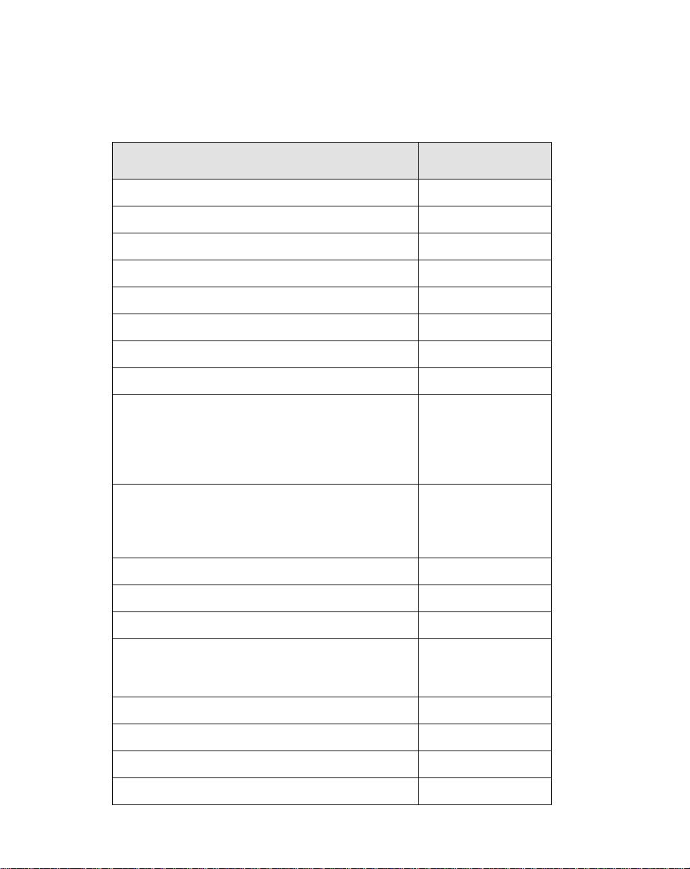
Optional Accessories 1
The following optional accessories can be used with the Stylistic 3400 pen tablet.
Refer to the instructions provided with these accessories for details on their use.
Peripheral/Accessory
Stylistic 3400 port replicator FMW42PR1
Stylistic 3400 mini-dock FMW42DS1
Stylistic 3400 high-usage cradle FMW42CR1
Stylistic 3400 wall-mount cradle FMW42CR3
Stylistic 3400 portfolio case FMWCC42
Stylistic 3400 slip case FMWCC43
Stylistic 3400 Antenna Cover Kit FMW42RC1
External floppy disk drive FMWFD2
USB keyboard (US) FMWKB5A
Infrared keyboard (US) FMWKB4A
Fujitsu Part
Number
(UK) FMWKB5B
(FR) FMWKB5F
(GR) FMWKB5D
(IT) FMWKB5E
(UK) FMWKB4B
(FR) FMWKB4F
(GR) FMWKB4D
Auto adapter FMWCB2
Pen tether FMWST2
Folding desk stand FMWDS3
AC adapter (US) FMWAC6A
(UK) FMWAC6B
(Euro) FMWAC6C
Stylistic 3400 battery pack (spare) FMW42BP1
Stylistic external battery charger FMW42BC1
Screen protectors (package of 12) FMWSP9
Stylistic pen (package of 5) FMW42PN1
2
Getting Started
Page 11
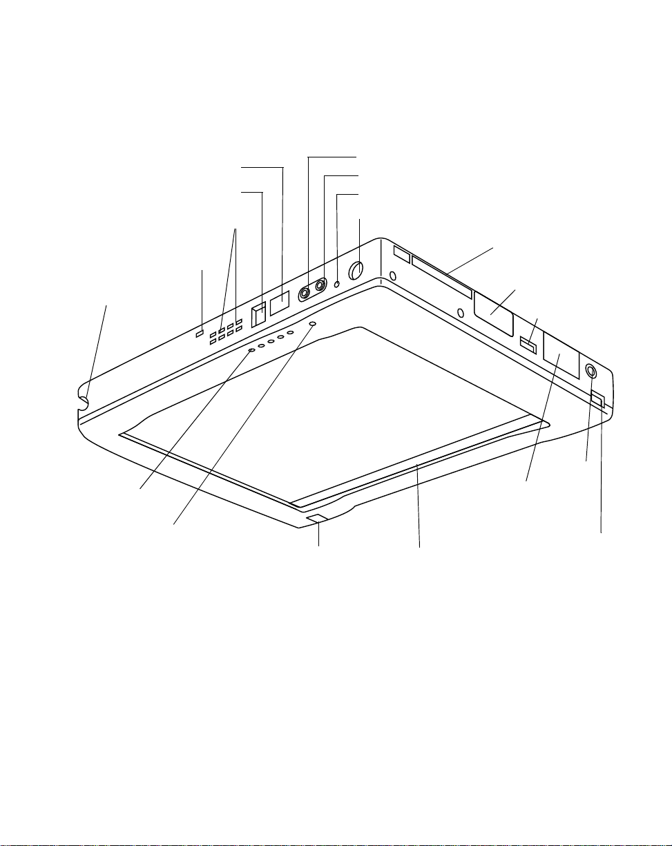
Stylistic 3400 Pen Tablet Features 1
Features and controls that you use to operate the Stylistic 3400 pen tablet are
described briefly below and illustrated in Fig ures 1-1 and 1-2. Details on using these
features and controls are provided later in this manual.
Pen Tether
Attachment P o int
Pen Holder
System
Status LEDs
Microphone
IrDA/FIR Port
Modem Port
Air Flow Vents
Headphone Jack
Microphone Jack
Reset Button
Suspend/Resume Button
Video Port
Hotpad AreaInfrared K e ybo ard Port
PCMCIA CardBus/
Zoom Video Slot
Floppy Drive Port
USB (A) Port
DC Input
Port Replicator
Latch Point
Figure 1-1 Stylistic 3400 Pen Tablet Features (Front View)
Front / Top / Right Features: 1
• System status LEDs: Indicate the operational status of the pen tablet and hard
disk drive, the charge level of the battery, and the status of the hovering mode.
• Pen: The main pointing device that you use to execute programs and enter data.
A pen holder is built into the pen tablet to store the pen when not in use.
Stylistic 3400 Pen Tablet Features
1
3
Page 12

• Suspend/Resume button: Allows you to suspend and resume pen tablet
operation in order to optimize battery life.
• Microphone Jack: Allows you to connect an external microphone.
• Headphone Jack: Allows you to connect a set of headphones.
• PCMCIA CardBus/Zoom Video slot: Allows you to install PC Cards in the
†
system.
• IrDA/FIR port: Provides an infrared interface fo r com mu nication with dev ic es
compliant with IrDA Standard Revision 1.1.
• Infrared keyboard port: The infrared port wraps around the front and bottom of
the display, and is used for communicating with a proprietary infrared keyboard
†
or mouse.
• Hotpads: Allows you to chang e se ttings for the display and speaker by tapping
with the pen.
• USB port A: Allows you to connect Universal Serial Bus-compliant devices to the
†
pen tablet. USB port B is located on the optional mini-dock or port replicator.
• Modem port: Allows you to connect a standard RJ-11 connector to the pen tablet’s
internal 56 Kbps modem.
Note: The port for the LAN element of the internal LAN/Modem module is available on
†
the optional mini-dock and/or port replicator.
• DC input connector: Allows you to connect the AC adapter or auto adapter.
• Reset button: Turns off the pen tablet in the event of system difficulty.
• Air flow vents: Provides secon dary cooling for p rocessor. (Do not ob struct the
vents.)
†
• Pen tether attachment point: Allows you to attach a pen tether.
• Port replicator latch point: Allows you to attach the system to a port replicator or
†
mini-dock.
• Floppy drive port: Allows you to attach a floppy disk drive to the system.
• Video port: Allows you to connect an external video monitor to the Stylistic 3400.
†
These peripherals and accessories are sold separately.
4
Getting Started
†
†
Page 13

Radio Cover Guide
Memory Cover
Battery
Release
Button
1
Speaker Hard Disk Drive Cover
System
Interface
Connector
Metal Contacts
(Power and USB)
Air Flow Vents
Battery Latch
Battery Pack
Kensington Lock Slot
Port Replicator Latch Point
Infrared Keyboard Port
Pen
Figure 1-2 Stylistic 3400 Pen Tablet Features (Rear View)
Rear / Bottom / Left Features: 1
• System interface connector: Allows you to connect the Stylistic port replicator,
†
Stylistic mini-dock, or other approved docking device.
• Speaker: Allows you to play back audio files without external ha rdware.
• Metal contacts: Allows you to place the pen tablet in an approved docking station
for high-insertion connection with power and USB interface.
†
• Removable battery pack: Can be removed and charged in an opt ional external
†
charger.
1
• Battery latch/battery release button: Used in conjunction to release the
removable battery pack.
†
These peripherals and accessories are sold separately.
Stylistic 3400 Pen Tablet Features
5
Page 14

• Air flow vents: Provides secon dary cooling for p rocessor. (Do not ob struct the
vents.)
• Port replicator latch point: Allows you to attach the system to a port replicator.
• Infrared keyboard port: The infrared port is located at the bottom and front of the
†
display, and is used for communicating with an infrared keyboard.
• Memory cover: Removable cover over the RAM chips.
• Radio cover guide: Provides alignment guides and latch points for the third-party
†
LAN radio solution.
• Hard disk drive cover: Covers the removable hard disk drive module.
• Kensington™ lock slot: Allows you to attach a Kensington
MicroSaver
†
These peripherals and accessories are sold separately.
TM
-compatible security cable.
†
†
6
Getting Started
Page 15
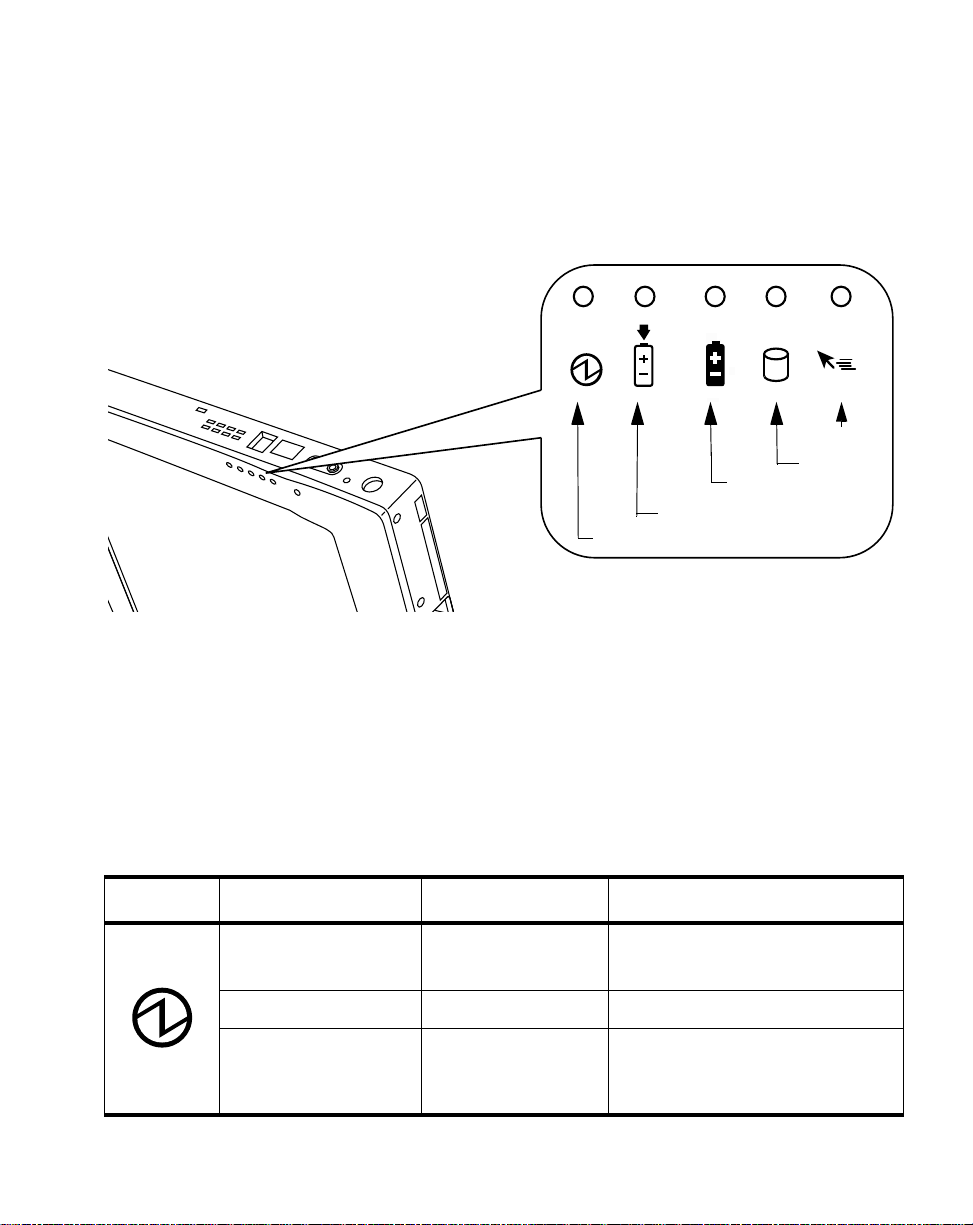
Status Display 1
Icons appear in the Status display indicating the status of system functions such as
system power and battery charge level. The location of icons in the Status display is
shown in Figure 1-3.
Hovering
Battery
Charge/DC In
Power
Figure 1-3 Status Display Icons
HDD
Table 1-1 explains how individual icons are displayed, and describes what the
variations of that display indica te. (If an icon is not displayed, it indicates that the
related system function is off or inactive.
Note: In the following table, a “blinking” LED flashes at the rate of once per second; an
LED that is “blinking, slow” flashes at the rate of one second on, five seconds off.
Table 1-1 System Status Indicators
Icon Mode/State LED State Remarks
Power
• On State
• Idle Mode
• Suspend-to-RAM Green, blinking
• Off State
• Save-to-Disk
Green, continuous
Off
Status Display
7
Page 16

Table 1-1 System Status Indicators
Icon Mode/State LED State Remarks
Charge/
DC Input
Battery
• On State
• Idle Mode
• Suspend-to-RAM
• Save-to-Disk
• Off State
• On State
• Idle Mode
• Suspend-to-RAM
with AC adapter
• Save-to-Disk,
with AC adapter
• Off State
Amber AC adapter and battery pack are
available and system is charging.
Green • AC adapter and battery pack
are available and system is not
charging (battery fully charged).
• AC adapter is available but
battery pack is not present.
Amber, blinking AC adapter and battery pack are
available and waiting to charge
(battery pack is out of thermal
range).
Off AC adapter is not available.
Green, continuous Battery pack charge is between
50%-100%
Amber, continuous Battery pack charge is between
13%-49%
Red, continuous Battery pack charge is between
0%-12%
Red, blinking There is a battery error.
Off Battery pack is not installed.
• Suspend-to-RAM,
without AC adapter
• Save-to-Disk,
without AC adapter
• Off State
8
Getting Started
Green, blinking slow Battery pack charge is between
50%-100%.
Amber, blinking slow Battery pack charge is between
13%-49%.
Red, blinking slow Battery pack charge is between
0%-12%.
Off If battery is inserted during power
off, LED blinks amber for 4
seconds to detect batte ry. Battery
status is displayed for 5 seconds
after that.
Page 17

Table 1-1 System Status Indicators
HDD
Access
Hovering
• On State
• Idle Mode
• Suspend-to-RAM
• Save-to-Disk
• Off State
• On State
(Hovering enabled)
• On State
(Hovering disabled)
• Suspend-to-RAM
• Save-to-Disk
• Off State
Green Displayed when hard disk drive is
accessed.
Off Hard disk drive is not being
accessed.
Green Hovering mode is enabled
Off Hovering mode is disabled.
Off
Status Display
9
Page 18

Connectors and Peripher al Int erfaces 1
Connectors and peripheral interfaces on the Stylistic 3400 pen tablet allow you to
connect a variety of devices. A general layout of the system interfaces is illustrated in
Figure 1-4. Specific interface locations are illustrated in Figure 1-5 and Figure 1-6.
IrDA Peripherals Phone AC Adapter
IrDA 1.1 RJ-11 2-pin DC-In 2-pin
FDD
External CRT
USB Peripherals
LAN Card
FAX/Modem Card
SCSI Card
SRAM Card
Flash Disk Card
Other
FDD 26-pin
VGA 15-pin
USB 4-pin
CardBus T ype II
68-pin
Metal Contact
8-pin
Port Replicator / Mini-dock / Cradle
Battery Connector
10-pin
Stereo Headphone
Jack 3-pin
Microphone Jack
2-pin
Port Replicator
Interface 200-pin
Figure 1-4 Connectors and Peripheral Interfaces
Battery
Headphones
Microphone
10
Getting Started
Page 19

USB (A)
Port
Floppy Drive Port
Video Port
DC Input
PCMCIA CardBus/Zoom Video Slot
Figure 1-5 Peripheral Connectors/Interfaces, Top and Right
System
Interface
Connector
High-Usage
Metal Contac ts
Modem Port
IrDA/FIR Port
Headphone Jack
Microphone Jack
Reset Button
Suspend/Resume Button
Kensington Lock Slot
Infrared Keyboard Port
Figure 1-6 Peripheral Connectors/Interfaces, Bottom and Left
Connectors and Peripheral Interfaces
11
Page 20

Table 1-2 provides a description of each peripheral connector on the Stylistic 3400
pen tablet. Each of the illustrated icons is printed on the pen tablet case.
Table 1-2 Peripheral Connectors/Interfaces
Connector/
Peripheral
DC input
connector
Video port
†
Fig.
Ref.
Pen Tablet Icon Purpose
1-1 Connect an exte rnal power source such as the
AC adapter or auto adapter.
1-1 Connect an external video monitor. Use of the
video port requires changing the Display Select
hotpad to enable the external monitor.
(LCD --> External CRT only --> Simultaneous)
Floppy drive
port
1-1 The floppy disk drive connector uses a special
interface that can be mated only with a Fujitsu
FMWFD2
floppy disk drive. Do not attempt to
connect any other type of unit to this connector.
Contact your reseller for more information.
USB (A) Port 1-1 Connect Universal Serial Bus-compliant devices
to the pen tablet. USB (B) port is located on the
optional Stylistic 3400 mini-dock.
PCMCIA
1-1
Install a Type II PC Card or Zoom Video card.
CardBus slot/
zoom video
Microphone
jack
1-1 Connect an exte rnal microphone. The internal
microphone is disabled when you plug in an
external microphone.
Headphone
jack
†
Open the connector door to access these connectors.
12
1-1 Connect stereo headphones or powered external
speakers. The internal speaker is disabled when
you plug in external headph ones or speakers.
Getting Started
Page 21

Table 1-2 Peripheral Connectors/Interfaces
Connector/
Peripheral
Fig.
Ref.
Pen Tablet Icon Purpose
IrDA/FIR port 1-1 An infrared transceiver built into the pen tablet
allows you to communicate with other devices
that are compliant with the IrDA Standard Rev.
1.1. Effective range for infrared communication is
about 3 feet, and within 15 degrees off of center.
A clear line-of-sight path must exist between the
IrDA port on the pen tablet and the IrDA
transceiv er on the othe r device.
Modem 1-1 Connect a telephone line to the optional internal
modem using a standard RJ-11 telephone plug.
High-Usage
Metal Contacts
1-2 Install the pen tablet in an approved docking
device. The contacts provide DC input and USB
interface.
System
interface port
1-2 Connect th e Sty listi c 3 40 0 po rt replicator or other
†
approved docking device. Refer to the
documentation accompanying the docking device
for more information.
Infrared
keyboard port
1-1,
1-2
An infrared receiv er buil t into the pen tab let allows
you to communicate with a wireless infrared
keyboard. The keyboard infrared port works
optimally between 10 to 30 cm (approximately
4 in. to 12 in.) from the keyboard infrared port,
located on the bottom edge of the pen tablet.
Ensure that there is a clear line-of-sight path
between the infrared receiver on the pen tablet
and the infrared transmitter on the keyboard.
TM
1-2
Kensington
Lock slot
†
Open the connector door to access these connectors.
The Kensin gton MicrosaverTM security slot allows
secure the pen tablet using
you to
Kensington-compatible locking devices.
Connectors and Peripheral Interfaces
13
Page 22

In addition to the connector and interface icons, there are a number of icons that illustrate
component orientation and buttons. These icons are illustrated in Table 1-3.
Table 1-3 Additional System Icons
Icon Description
Battery Indicates the locati on of the remo vable
Battery Release Button Indicates the battery release button.
Battery Release Latch, Open Indicates the position of the battery latch
Battery Release Latch, Closed Indicates the position of the battery latch
Suspend/Resume Button Indicates the Suspend/Re sum e b u tton .
Reset Button No icon Powers down the system in the event of
Icon
Illustration
Purpose
battery cover.
that releases the battery.
that secures the battery.
system difficulty.
14
Getting Started
Page 23

Chapter 2
Using the Stylistic 3400 Pen Tablet
This chapter covers the fundamental concepts, basic system operation and use, and
system functions of the Stylistic 3400 pen tablet. You should familiarize yourself with
this information before you attempt to operate the system.
System States 2
Before you begin using the Stylistic 3400 pen tablet, review the different system states
(or modes) that the pen tablet can use. Being familiar with these system states will
help you determine whether it is appropriate to turn on, resume, suspend, or shut
down the system when you begin a new session or end your current session. System
behavior for each system state is described briefly in the following, with each system
state listed in decreasing order of power usage :
• On state
The system is running and the display screen is on.
• Idle state
Some system functions are regulated or turned off to conserve power . The display
screen may be turned off. The system r eturns to the On state whe n pen activity or
other input is detected.
• Suspend-to-RAM mode
System operation is suspended. Most system functions are turned off to conserve
power. Power to memory is on, maintaining data in programs that were running
before system operation was suspended. The system does not respond to the pen
or other input when in Suspend-to-RAM mode. Refer to the “Resumin g Sy st em
Operation” section later in this chapter for information on returning the system to
the On state.
• Save-to-Disk mode
System operation is suspended. All system functions are turned off to conserve
power. Active data in programs that were running before suspending system
operation is stored on the hard disk drive. The system does not r espond to the pen
or other input. Refer to the “Resuming System Operation” section later in this
chapter for information on returning the system to the On sta te.
15
Page 24

• Off state
All system functions are turned off to conserve power. The system does not
respond to the pen or other input. The syste m boots at the next system power-on.
Note: The system consumes the same amount of power whether it is in Save-to-Disk
mode or the Off state.
Your system may be configured to enter some of these states automatically after a
period of inactivity to conserve battery power.
When you use the Stylistic 3400 pen tablet, you can change the current system state
in a number of ways, depending on which state the system is in. To determine the
current system state, observe the Power icon in the Status display. Table 2-1 gives the
different system states represented by the Power icon and describes how you can
change the system state from the current state.
Table 2-1 Changing System States
Power Icon
Appearance
Power icon displayed
continuously
Power icon blinking
Power icon not
displayed
Information in Table 2-1 is supplied to help you understand which system states your system
*
can enter from the current system state. Refer to the procedures on starting the system,
shutting down the system, suspending system operation, and resuming system operation
given later in this chapter.
Current State
On State
or
Idle State
Suspend-to-RAM
Off State
or
Save-to-Disk
†
To Change State
To enter the Off state, shut down the system
using the Start menu on your system.
To enter Suspend-to-RAM or Save-to-Disk
state, suspend system operation using either
a hardware or software suspend.
†
To enter the On state, resume system
operation by pressing the Suspend/Resume
button.
To enter the Off state, resume system by
pressing the Suspend/Resume button, then
shut down your system.
To enter the On state, start your system, or
resume system operation by pressing the
Suspend/Resume button.
*
†
†
Your system may be configured to use either Suspend-to-RAM mode or Save-to-Disk mode.
16
Using the Stylistic 3400 Pen Tablet
Page 25

P owering Up the P en Tablet 2
Follow the procedure below to start the Stylistic 3400 pen tablet. Before you begin,
confirm that the system is in the Off state. To do so, observe the Status display. If the
Power icon is not visible in the Status display, th e system is in the Off state or in
Save-to-Disk mode a nd it is safe to perform this p rocedure. If the Power ic on is
visible (either blinking or on continuously), do n ot perform this procedure. See
“System States” earlier in this chapter for details on operational modes represented
by the Power icon.
1. Press the Suspend/Resume button to start the system.
2. Ensure that the battery pack in your pen tablet is sufficiently charged, or connect
an external power source such as the AC adapter or auto adapter to your pen
tablet. See “Status Display” in Chapter 1 to determine the percentage of charge
represented by the Battery Gauge icon in the Status display.
After performing system initialization, the system starts the operating system
installed on the hard disk drive. Once the operating system is running, you can use
the system.
Powering Up the Pen Tablet
17
Page 26

Shutting Down the System 2
Follow these steps to shut down and turn off your system:
1. If system operation has been suspended, resume system operation. See
“Resuming System Operation” later in this chapter for details.
2. Save your work and close all running programs.
3. Choose Shut Down from th e Windows (98, NT Workstation, or 2000) Start menu
and carry out the Shut Down command.
The system is now in the Off state.
Suspending Syste m Oper ati on 2
The Stylistic 3400 pen tablet allows you to suspend the system operation without
closing programs or exiting the operating system. Use this feature to conserve battery
power when a system shutdown is not practical or when the battery needs to be
changed.
To suspend system operation:
1. Pr ess the Suspend/Resume button, or carry out the Standby command fr om your
operating system or power management program. (If your system is configured
to suspend operation using Save-to-Disk mode, which is explained later in this
procedure, a message is displayed while data is saved to your hard disk.)
Caution
If you are replacing the battery pack,
suspended and the power icon is flashing
pack. Failure to do so could result in loss of your unsaved data.
The Power icon either flashes (Suspend-to-RAM) or is not displayed
(Save-to-Disk) when system operation is suspended, depending on how your
system is configured. At this point, programs th at were running are stopped,
active data is saved, and the system enters one of two different low-power states,
or suspend modes, as explained in the following paragraphs.
2. Observe the Power icon in the Status display to determine which suspend mode
your system is using.
18
Using the Stylistic 3400 Pen Tablet
wait until system operation is
before you remove the battery
Page 27

• Power icon is blinking: Suspend-to-RAM mode
In this mode, active data is saved by maintaining power to RAM while most
other system components are powered off. The Battery Gauge icon in the
Status display indicates the battery charge level.
• Power icon is not displayed: Save-to-Disk mode
In this mode, active data is stored on the hard disk drive and po wer usage is
reduced to the same level used in the Off state. When the system is in
Save-to-Disk mode, the Battery Gauge icon is not visible in the Status display.
In this mode, there is no danger of losing data if battery power is lost.
If you have successfully performed this procedure, system operation is now
suspended. Refer to “Resuming System Operation” later in this chapter to resume
system operation. Also, note the following with regard to suspending system
operation:
• You can remove the battery pack while the system is in Suspend-to-RAM or
Save-to-Disk modes in order to install a charged battery pack. To prevent losing
unsaved data, wait until system operation has suspended before you remove the
battery pack.
• Y our system may be configured to suspend operation automatically after a period
of inactivity.
• Your system may be configured to enter Save-to-Disk mode automatically after a
period of time in Suspend-to-RAM mode.
• The system uses a small amount of battery power when in Suspend-to-RAM
mode. Eventually, the battery will become fully discharged.
Note: If you will not be using the system for an extended period of time, shut down the
system rather than using Suspend-to-RAM mode.
• If the battery pack charge drops to a Low-Battery Warning level while the system
is running, the system will beep periodically. If this occurs, suspend system
operation, shut down the system, or attach an external power source, such as the
AC adapter, to the pen tablet.
• If the battery charge drops to a Critically Low level while the system is running,
the system is forced into a pre-selected mode (Suspend-to-RAM or Save-to-Disk).
If this occurs, you must either install a charged battery pack, or connect an
appropriate external power source such as the AC adapter before you can resume
system operation. (If the battery charge drops to a Critically Low level while the
system is in Suspend-to-RA M mode, the system stays in Suspend-to-RAM mode
until power is restored or totally dissipated.)
Suspending System Operatio n
19
Page 28

• Suspending system operation interrupts data communications; therefore, some
programs may block the system from suspending to prevent an interruption.
• The suspend action of the Suspend/Resume button may be disabled to prevent
accidental interruption. If this is the case, pressing the Suspend/Resume button
will not suspend system operation as described her e. (In this case, suspend mode
can only be achieved using the system softwa re). Contact yo ur local help desk or
reseller if your system configuration is not suitable.
• If your system is equipped with a PC Card that allows you to connect to a wired
or wireless network, you may be logged off the network after a period of
inactivity while system operation is suspended. Contact your network
administrator or local help desk for details on log-off parameters for your
network.
Resuming System Operation 2
To resume system operation, (from either Suspend-to-RAM or Save-to-Disk modes),
press the Suspend/Resume button.
• From Suspend-to-RAM mode
Status lights indicate that the system state is changing. It may take up to a minute
before the system returns to the On state and system operation resumes. Note that
the display turns on shortly before the pen becomes active due to the power-up
sequences observed by the system.
• From Save-to-Disk mode
Active data is read from the hard disk drive, and the system returns to the On
state after a short period of time.
Note that power to several system components must be restored before system
operation resumes. Allow sufficient time for system operation to resume before
attempting to use the system. If your system uses Save-to-Disk mode, it will take
longer to resume operation as compared to using Suspend-to-RAM mode. Time is
needed to read data from the hard disk drive.
• Use the system as you normally would once system operation resumes.
All programs resume at the point where execution stopped when system operation
was suspended.
20
Using the Stylistic 3400 Pen Tablet
Page 29

Using Hotpads 2
Hotpads are pen-active areas below the system display that you can us e to adjust the
settings of the display and speaker settings while the system is running. Separate
hotpads are available for enabling the right mouse button function and the pen
hovering mode.
To use a hotpad, tap directly on it with the pen. You can also press and hold the pen
tip against the Volume and Brightness hotpa ds to automatically repeat the hotpad
function. The location of each hotpad is shown in Figure 2-1.
Programmable Speaker
Icon
On/Off
Volume
Down
Volume
Up
Display
Select
Figure 2-1 Hotpads
A summary of each hotpad’s function is given below:
• Programmable hotpad
This hotpad can be programmed for application -specific functions. Contact your
local help desk or reseller if you need assistance using the Programmable hotpad.
• Volume hotpads
These hotpads set the volume of the pen tablet speaker or headphones, if used.
(Note that the internal speaker is disabled when headphones are plugged in.)
• Speaker On/Off hotpad
This hotpad turns the pen tablet speaker or headphones on or off. When you tap
this hotpad to turn on the speaker or headphones, the system beeps.
Brightness
(8 levels)
Right
Mouse
Pen
Hovering
Using Hotpads
21
Page 30

• Display Select hotpad
This hotpad allows you to choose the pen tablet display screen, an external video
monitor, or both as the selected system display(s). The pen tablet display screen
appears blank when an external monitor alone is selected.
• Brightness hotpads
These hotpads allow you to adjust the display brightness. The brightness can be
adjusted to eight levels.
• Right Mouse hotpad
This icon is used to switch the pen function from left mouse button to right mouse
button emulation. T o generate a right mouse button single click, tap on the hotpad
icon once and then tap once on the display. To generate a right mouse button
double click, tap on the hotpad icon once and then double tap on the display.
• Pen Hovering hotpad
This hotpad switches the hovering mode on or off; throughout the hovering
mode, the hovering status indicator is lit. Pen Hovering mode provides the user
with better cursor control. When the hovering option is enabled, the cursor can be
positioned over an icon without activating it. This is useful when you are
attempting to read pop-up text associated with an icon, simulating mou se
rollover, selecting a small icon, or begin ning a paint session.
Using the Pen 2
You can use the Stylistic 3400 pen to generate and create electronic “ink”, to select
items, and to navigate through programs on the pen tablet. The pen can be used like
a two button mouse when used in conjunction with the right-mouse button hotpad.
Programs which support handwri ting recognition allow you to write characters
directly on the screen with the pen and then translate your printed text into
keyboard-style input.
Caution
• Ensure that a screen protector is installed on the pen
tablet screen before you use the pen. The warranty does
not cover a scre en that is scratched as a result of not using
a screen protector.
• Use only the pen stylus provided with your pen tablet. Do
not use substitutes that were not designed for the Stylistic
3400.
22
Using the Stylistic 3400 Pen Tablet
Page 31

To toggle between using the pen for inking and usin g it as a mouse, click on the
small pen icon in the system tray at the bottom right of the screen.
Here are some hints on using the pen like a two-button mouse on a desktop system:
• To select an object, tap the mouse tip on the object once. This functions like a
mouse button click with the left mouse button.
• To “double-click” an object, tap twice on the object quickly.
• To generate a “right mouse button single-click”, tap on the hotpad icon once and
then tap once on the display. To generate a “right mouse button double click”,
tap on the hotpad icon once and then double tap on the display.
• To move, or “drag”, an object on the screen, place the pen tip directly over the
object, then as you hold the pen tip against the screen, move the pen.
Calibrating the pen 2
Calibration of the pen adjusts the cursor position on the screen relative to the
position of the pen tip. You calibrate the pen to adjust the distance error between
where the pen actually touches the screen and where the system “thinks” the pen is
touching. If the event you wish to invoke is not displa yed under the pen tip when
you use the pen, you should calibrate the pen.
Pen calibration may be required due to the following situations:
• The pen is being used for the first time.
• The previous user of the Stylistic 3400 pen tablet writes with the opposite hand or
at a different pen angle.
• The system has been in use for some time and the pen has not been recalibrated.
• The original system image has been restored.
To Calibrate the Pen 2
1. Open the Control Panel from the Start|Settings menu, and double-tap the Pen
Configuration icon. Select the Calibration property sheet, then click on Pen
Calibration.
2. Position the Stylistic 3400 pen tablet as you normally would during use. Be sure to
hold the pen at the angle that you regularly use. Touch the screen only with the
pen tip; if you inadvertently touch the screen with your finger or hand during the
calibration process, faulty calibration may result.
Using the Pen
23
Page 32

3. Perform the calibration steps according to the instructions on the screen. The
calibration utility displays a cross-hair symbol in the middle and corners of the
screen, one corner at a time. Hold the pen as you normally would while using the
system and, as accurately as possible, tap the center of each crosshair as it is
displayed.
A dialog box is displayed after you tap the last of the four cross-hair symbols. Tap
the screen within 20 seconds if you wish to save your new calibration settings. If
you don’t tap the screen within 20 seconds, the default calibration settings will be
used.
4. When the Verify New Pen Calibration Settings window appears, choose one of
the following steps.
• If you are satisfied that you tapped the cross-hairs accurately, tap Yes. The
taps that you performed in step 3 are then used to calibrate the screen.
• If you do not want to use the new calibration, tap No.
• If you want to enter a new calibration, tap Recalibrate. The calibration
instructions reappear.
If you have successfully performed the procedure above, the pen is now recalibrated,
and you can use the system as you normally would.
Replacing the Pen 2
With use, the pen tip may become worn or may pick up foreign particles that can
scratch the screen. A damaged or worn tip may not move freely, causing
unpredictable results when using the pen. If your pen exhibits these problems,
replace the pen by contacting your reseller.
Charging the Ba ttery P a c k 2
The Stylistic 3400 battery pack can be charged while it is installed in the pen tablet.
To do so:
1. Connect a DC power source, such as the AC adapter, to the DC input connector
on the pen tablet. The DC Input icon appears in the Status display. If the battery
pack charge level is below 90%, the battery pack begins charging and the
24
Using the Stylistic 3400 Pen Tablet
Page 33

Charging icon appears in the Status display. If the battery pack charge is 90% or
higher when you connect DC power, the battery pack will not charge, preventing
overcharging the battery pack.
2. Look at the Battery Gauge icon in the Status display to determine the percent of
charge in the battery pack. See “Status Display” in Chapter 1 of this manual for a
description of the Battery Gauge icon.
As long as DC power remains connected to th e pen tablet , the cha rging process
continues until the battery pack charge reaches 100%. Charge times shown in Table
2-2 are for a fully discharged battery pack charging both while the pen tablet is and is
not in use.
Table 2-2 Battery Pack Charging Time
Battery Pack Charge
Level Reached
90% 3 hours 6 hours*
100% 4 hours 8 hours*
Approximate Charge Time
(tablet not in use)
Appro xim ate Charge Time
(tablet in use)
* Depends upon the applications in use.
Also note the following with respect to charging the battery pack:
• You can use the system, suspend system operation, or shut down and turn off the
system without interrupting the charging process; however, using the system
while the battery pack is charging will cause the battery pack to charge at a slower
rate, as noted in Table 2-2.
• As noted in the procedure above, the system will not begin charging the battery
pack if the battery pack charge level is 90% or higher when the system is initially
connected to external DC power. (This prevents the battery pack from being
overcharged.)
• The Stylistic 3400 battery pack uses Lithium ion battery cells which have no
“memory effect.” You do not need to discharge the battery pack before you begin
charging.
Charging the Battery Pack
25
Page 34

Removing and Installing the Battery Pack 2
The battery pack can be removed from the pen tablet and swapped with a charged
battery pack. The battery pack can then be charged in an external charger if one is
available. To remove the battery pack from the pen tablet:
1. Choose one of the following:
• If a charged battery pack is available, you can suspend system operation. A
built-in “bridge” battery will maintain the system in Suspend-to-RAM mode
for about 5 minutes while the battery pack is removed; this allows time for
replacement with a charged battery pack.
• If a charged battery pack is not available, save your work and close all
running programs, then shut down the system or Save-to-Disk.
• Plug in an external DC power source.
2. Press and hold the battery release button. (See Figure 2-2.)
3. While holding the button, slide the battery release latch in the direction indicated
in Figure 2-2. The edge of the battery pack lifts away from the surface of the
system.
4. Remove the battery pack from the pen tablet.
If you are using an external battery charger, refer to the instructions provided with
the battery charger.
To install the battery pack:
1. Orient the battery such that the battery connector is positioned over the connector
in the empty battery pack tray. Lay the battery pack into the tray and press it
firmly into the tray until it is seated. When it is properly seated, the battery release
latch should move towards the battery release button.
2. When the battery is firmly seated, press the battery release latch towards the
battery release button until the release button pops up to the level of the system.
Once the battery pack is installed, you can resume system operation or start your
system and use the system normally.
26
Using the Stylistic 3400 Pen Tablet
Page 35

Battery Release Button Battery Release Latch
Battery Cover
Figure 2-2 Removing the Battery Pack
Tips f or Conserving Batte ry P ow er 2
You can extend the charge life of your battery pack by conserving battery power. A
fully charged battery pack can run the system under norm al use in most applications
for approximately 2.5 hours*. Your results may vary depending on your applicati on
and how the system is configured. Here are some suggestions to help you conserve
battery power:
• Use an external power source such as the AC adapter to power the system when
possible.
• Suspend system operation if you know that you won’t be using the system for a
while.
• Shut down the system if you won’t be using the system for an extended period of
time.
• Use power management timeouts (accessible through the BIOS setup) to help you
conserve power automatically. Contact your reseller before modifying the BIOS.
* Battery life is dependent upon a number of factors: operating system, power
settings, and applications in use.
Tips for Conserving Battery Power
27
Page 36

Operation of the Bridge Batte ry
When installed in the pen tablet, the battery pack provides power to some system
components—even when the system is in the Off state. When the battery pack is
removed, power is supplied to these components by a “bridge” battery that is built
into the pen tablet.
The bridge battery is not designed for long-term operation. To maintain the bridge
battery properly, observe the following measures:
Note: The system arrives with the bridge battery in a discharged state.
• To prevent draining the bridge battery, always store the pen tablet w ith a c harged
battery pack installed.
• If the bridge battery becomes drained, it takes approximately 11 hours for it to be
fully recharged.
• The bridge battery charges when the AC Adapter is connected and the system is
in On or Off states or Suspend mode. It charges from the battery only when the
system is in the On state.
Modem Connection 2
Note: • The internal 56 Kbps LAN/modem module installed in the Stylistic 3400 pen
tablet has actual maximum transfer rates of 53 Kbps (receive), 33.6 Kbps (send),
and 14.4 Kbps (fax). Download rates are limited to 53 Kbps in the United States
due to FCC restrict ions.
• The LAN portion of the internal LAN/modem module can only be used when the
system is used with th e o ptional mini-dock or port replicator; there is no LAN
port on the system itse l f .
The Stylistic 3400 pen tablet is designed to accept a standard RJ-11 telephone plug.
Connect the plug to the modem jack located on the top of the pen tablet, to the left of
the IrDA port (reference Figure 1-1). The telephone plug can be installed whether or
not the pen tablet has power applied.
If you need assistance configuring the Stylistic 3400 pen tablet modem or LAN,
contact your local help desk or your reseller.
28
Using the Stylistic 3400 Pen Tablet
Page 37

PC Card Slot 2
The Stylistic 3400 pen tablet PC Card slot allows you to install a Type II PCMCIA
CardBus card.
To install a PC card, position the side with the arrow facing up (i.e., when looking at
the tablet’s display side, the arrow on the card should be visible.) Slide the card into
the PC Card slot, and press it firmly to ensure proper seating.
To install a radio PC card, see the documentation accompanying the Antenna Cover
Kit (FMW42RC1). The Antenna Cover Kit is designed to cover the radio antenna to
protect it from damage.
If you need assistance installing a PC Card in the Stylistic 3400 pen tablet, contact
your local help desk or your reseller.
PC Card Slot
29
Page 38

30
Using the Stylistic 3400 Pen Tablet
Page 39

Chapter 3
Care and Maintenance
This chapter gives you pointers on how to care for and maintain your Stylistic 3400
pen tablet.
Protecting the Di splay Screen 3
The Stylistic 3400 pen tablet is designed to provide you with years of service. Using a
screen protector will help ensure that the screen remains as clear as possible. When
installed, the screen protector becomes a durable, replaceable writing surface that
protects the display screen from abrasion.
To obtain additional screen protectors use Fujitsu part number FMWSP9 (12-pack)
when ordering. Additional information about installation is included w ith the screen
protectors.
Caution
During normal use of the pen tablet, small particles from the
environment can become embedded in the pen tip and
scratch the screen. To prevent scratching the screen, ensure
that a screen protector is installed before using your pen
tablet. The w a rranty does not cov er a sc ree n th at i s sc ra tc hed
as a result of not using a screen protector.
To install a new screen protector on your pen tablet:
1. If a screen protector is already installed on the display screen, remove it before
installing the new screen protector.
The screen protector is held onto the display screen surface by a thin strip of
adhesive around the edges. A notch in one corner of the screen protector allows
you to slide your fingernail under the screen protector for easy removal.
2. Clean the display by wiping the screen surface gently using a so ft cotton cloth
dampened with isopropyl alcohol. Ensure that all residue has be en removed fr o m
the screen before applying a new screen protector.
31
Page 40

Caution
The Stylistic 3400 pen tablet is
liquids on the system or wash it with a heavily soaked cloth.
not waterproof
. Do not pour
3. Remove the protective coating from the adhesive side of the screen pr otector first.
4. Apply the screen protector to the display screen surface. When doing so, orient
the screen protector with the adhesive side of the screen protector facing the
display screen and the notched corner of the screen protector toward the lower
left corner of the display screen.
5. Apply pressure to the screen protector with your finger using a continuous
wiping motion along the edges. The adhesive sets completely within 48 hours.
To ensure a good seal between the screen protector and the display, do not lift the
screen protector from the display once it has been applied.
6. Remove the protective plastic cover from the face of the screen protector.
7. Clean any residue left behind by the protective coating from the exposed surface
of the screen protector by wiping gently with a soft cotton cloth dampened with
isopropyl alcohol. Wipe the screen protector with a soft dry cloth to remove any
low-tack adhesive; this will help prevent the pen tip from squeaking.
The screen protector is now installed.
Storing the Styli stic 34 00 Pen Tablet 3
Caution
Be sure not to store your Stylistic 3400 with the screen side
down, otherwise damage to the display may occur.
Store the Stylistic 3400 pen tablet in the Off state with a fully charged battery pack
installed. The Stylistic 3400 battery pack always provides power to some system
components, even when the system is in the Off state. If the system is stored with the
battery pack removed, these components are powered by the system’s internal
bridge battery. The bridge battery is not designed for extended use and will
discharge in a short period of time; this could result in damage to the batteries. You
can store the pen tablet in the Off state for about 30 days with a fully charged battery
32
Care and Maintenance
Page 41

pack installed. After this period, the battery pack should be recharged or replaced
with a charged battery pack.
Av oiding Overheating 3
The Stylistic 3400 pen tablet monitors its internal temperature. As the internal
temperature approaches the tolerable limits of heat-sensitive components, system
functions are automatically limited or turned off to prevent damage.
To avoid overheating the pen tablet, do not obstruct the air vents on the top and
bottom edges of the pen tablet.
Cleaning the Disp la y S creen 3
To clean the pen tablet display screen, wipe the screen surface gently using a soft
cotton cloth slightly dampened with water or isopropyl alcohol.
Caution
The Stylistic 3400 pen tablet is
liquids on the pen tablet or wash the pen tablet with a heavily
soaked cloth.
not waterproof
. Do not pour
Avoiding Overheating
33
Page 42

Troubleshooting 3
Solutions to some common problems ar e described in the following sections. If you
are experiencing a problem with your Stylistic 3400 pen tablet that you cannot solve
by taking the actions described, contact your local help desk or yo ur res e ller f or
further assistance.
System Will Not Resume Operation 3
If the system will not resume operation after system operation has been suspended,
check the following possible causes:
• The battery pack may either be defective, or discharged to the critically low level.
When the battery pack reaches the critically low level, the system is forced into
Suspend-to-RAM mode to avoid a total system power failure. To correct this
problem, either connect an external power supply (such as the AC adapter), or
install a charged battery pack in the pen tab let.
• The system may be at the critical thermal limit. To avoid damage to heat-sensitive
components, the system enters Suspend-to-RAM mode when it gets too hot.
System operation cannot be resumed until the pen tablet cools off to a tolerable
temperature. Move the pen tablet to a cooler location.
Display Screen Is Blank or Difficult to Read 3
If the display screen on your Stylistic 3400 pen tablet appears blank or is unreadable,
confirm that the system is running (th e P ower icon is displayed continuously on the
Status display), and check the following:
• The system brightness may be set too low, causing the screen to appear too dark.
Use the brightness hotpad to adjust the screen brightness.
• An external monitor may be selected. Tap on the Display Select hotpad to
determine whether the pen tablet display screen is selected.
• The video timeout may have expired. Tap on the display screen to reactivate the
display. Note that this is a normal, power-saving feature.
Cursor Is Not Tracking Pen 3
If the cursor on the screen appears to be misaligned with the pen or is not accurately
tracking the pen, calibrate the pen. See “Calibrating the Pen” in Chapter 2 for details.
34
Care and Maintenance
Page 43

Infrared Data Transfer Is Not Working 3
If you are experiencing problems transferring data over the system’s infrared
interface, note the following:
• Can the IrDA port on the pen tablet “see” the IrDA port on the other device? A
direct line-of-sight path must exist between the IrDA port on the pen tablet and
the IrDA port on the other device.
• The distance between the two devices must not be more than approximately 3 feet
or 1 meter.
• The viewing angle from the IrDA port on the pen tablet must not be more than 15
degrees from a center line between the IrDA port on the pen tablet and the IrDA
port on the other device.
• The device with which you are trying to communicate must be compliant with the
IrDA Stand ard Revision 1. 1 (or 1.0).
P en Tablet Is Not R esponding to the Pen 3
If your pen tablet is not responding to the pen, connect an external keyboard to the
system to see if it responds to keyboard commands. If the system doesn’t respond to
the keyboard, the application or system may have crashed, and it may be necessary
to reset the system.
Audio Volume Too Low 3
If the audio volume on your pen tablet speaker or external headphones is too low,
check the following:
• Ensure that the speaker (or headphone output if using headphones) is enabled. T o
do so, tap the Speaker Mute hotpad. The system beeps when the speaker or
headphone output is turned on using the hotpad.
• Ensure that the volume level set with the Volume hotpads is set to an audible
level.
• Ensure that the mute box in the system volume control (accessible from the
system tray) is not set.
• Ensure that any volume control in your audio software is set to an audible level.
Troubleshooting
35
Page 44

Configuring Peripherals Interfaces 3
Certain peripheral devices can be disabled during the BIOS Setup. If the peripheral
interface you want to use does not appear to be working with your peripheral device,
ensure that it is enabled in the BIOS. Contact your local help desk or reseller if you
need assistance using BIOS Setup.
36
Care and Maintenance
Page 45

Appendix A
Agency Notices
UL Notices 3
Cautions
• For continued protection against the risk of fire, replace only with the same type and
rating of fuse.
• There is a danger of explosion if the CMOS battery is incorrectly replaced. Replace
only with the same or equivalent type recommended by the manufacturer. Dispose of
used batteries according to manufacturer's instruction.
• Changes or modifications not expressly approved by Fujitsu PC Corp. could void this
user’s authority to operate the equipment.
Warnings
• The CMOS battery may explode if mistreated. Do not recharge, disassemble, or
dispose of in fire.
• For a spare battery pack, order only Fujitsu Model
• To charge the battery pack
battery charger model
FMW42BP1
FMW42BC1
externally, use only a Stylistic external
.
FMW42BP1
.
FCC Notices 3
This equipment has been tested and found to comply with the limits for a Class B
digital device, pursuant to Part 15 of the FCC rules.
Changes or modifications not expressly approved by Fujitsu PC Corporation, could
void the user’s authority to operate the equipment.
Notice to Users of Radios and Television 3
These limits are designed to provide reasonable protection against harmful
interference in a residential installatio n. This equipment generates, uses, and can
radiate radio frequency energy and, if not installed and used in accordance with the
instructions, may cause harmful interferen ce to radio communications. However,
there is no guarantee that interference will not occur in a particular installation. If the
equipment does cause harmful interference to radio or television reception, which
Agency Notices
37
Page 46

can be determined by turning the equipment off and on, the user is encouraged to try
to correct the interference by one or more of the following measures:
• Reorient or relocate the receiving antenna.
• Increase the separation between the equipment and receiver.
• Connect the equipment into an outlet that is on a different circuit than the
receiver.
• Consult the dealer or an experienced radio/TV technician for help.
Shielded interconnect cables must be employed with this equipment to ensure
compliance with the pertinent RF emissions limits governing this device.
Notice to Users of the US Telephone Network 3
The Stylistic 3400 pen tablet is supplied with an in ternal modem which complies
with Part 68 of the FCC rules. On the pen tablet is a label that con tains the FCC
Registration Number and Ringer Equivalence Number (REN) of this system, along
with other information. If requested, users must provide their telephone company
with the following info rmation:
• The telephone number to which the pen tablet is connected
• The Ringer Equivalence Number (REN) for this equipment
• The information that the system requires a standard modular jack type USOC
RJ-11C which is FCC Part 68-compliant
• The FCC Registration Number
This equipment is designed to be connected to the telephone network or premises
wiring using a standard mod ular jack type USOC RJ-11C which is FCC Part
68-compliant.
The REN is used to determine the number of devices you may connect to your
telephone line and still have all those devices ring when your number is called.Too
many devices on one line may result in failure to ring in response to an incoming call.
In most, but not all, areas, the sum of all of the devices should not exceed five (5). To
be certain of the number of devices you may connect to your line, as determined by
the RENs, contact your local telephone company .
If this equipment causes harm to the telephone network, your telephone company
may discontinue your service temporarily. If possible, they will notify you in
advance. If advance notice is not practical, they will notify you as soon as possible.
You will also be advised of your right to file a complaint with the FCC.
38
Appendix
Page 47

This fax modem also complies with fax branding requirements per FCC Part 68.
If you experience trouble with this equipment, please contact your support
representative.
Your telephone company will probably ask yo u to disconnect this equipment from
the telephone network until the problem is corrected and you are sure that th e
equipment is not malfunctioning.
This equipment may not be used on coin service telephones provided by your
telephone company. Connection to party lines is subject to state tariffs. Contact your
state’s public utility commission , p ublic services commission, or corporation
commission for more information.
FCC rules prohibit the use of non-hearing aid compatible telephones in the following
locations or applications:
• All public or semipublic coin-operated or credit card telephones.
• Elevators, highways, tunnels, (automobile, subway, railroad, or pedestrian) wher e
a person with impaired hearing might be isolated in an emergency.
• Places where telephones are specifically installed to alert emergency authorities
such as fire, police, or medical assistance personnel.
• Hospital rooms, residential health care facilities, convalescent homes, and prisons.
• Workstations for the hearing impaired.
• Hotel, motel, or apartment lobbies.
• Stores where telephones are used by patrons to order merchandise.
• Public transportation terminals where telephones are used to call taxis or to
reserve lodging or rental cars.
• In hotel and motel rooms at least ten percent of the rooms must contain hearing
aid compatible telephones which will be provided to hearing impaired customers
on request.
DOC (Industry Canada) Compliance Notices 3
This digital apparatus does not exceed the Class B limits for radio noise emissions
from digital apparatus as set forth in the radio interference regulations of the
Canadian Department of Communications.
Le présent appareil numérique n’émet pa s de bruits radioélectriques dépassant les
limites applicables aux appareils numériques de classe B prescrites dans le règlement
Agency Notices
39
Page 48

sur le brouillage radioélectrique édicté par le Ministère des Communications du
Canada.
Notice to Users of Radios and Television 3
This Class B digital apparatus meets all requirements of the Canadian
Interference-Causing Equipment regulations.
Cet appareil numérique de la classe B respecte toutes les exigences du règlement sur
le matériel brouilleur du Canada.
Notice to Users of the Canadian Telephone Network 3
The Canadian Industry Canada label identifies certified equipment. This certification
means that the equipment meets certain telecommunications network protective,
operational, and safety requirements. The Department does not guarantee the
equipment will operate to the user’s satisfaction.
Repairs to telecommunication equipment should be made by a Canadian author ized
maintenance facility. Any repairs or alterations not expressly approved by Fujitsu PC
Corp. or any equipment failures may give the telecommunications company cause to
request the user to disconnect the equipment from the telephone line.
The connecting arrangement code for this equipment is CA11A.
The Load Number is 0.2.
The Load Number assigned to each telephone terminal device denotes the
percentage of the total load to be connected to a telephone loop or circuit to be used
by the device to prevent overloading. The termination on a loop may consist of any
combination of devices such that the total of the load numbers o f all devices does not
exceed 100.
Caution
For safety, users should ensure that the electrical ground of the
power utility, the telephone lines, and the metallic water pipes are
40
connected together. Users should
connections themselves but should contact the appropriate electric
inspection authority or electrician. This may be particularly
important in rural areas.
Appendix
attempt to make such
not
Page 49

Av is Aux Utilisa t eurs Du Réseau Téléphonique Canadien 3
L’étiquette canadienne Industrie Canada identifie l’équipement certifié. Cette
certification signifie que l’équipement satisfait certaines normes de protection,
d’exploitation et de sécurité des réseaux de télécommunications. Le département ne
garantit pas le fonctionnement de l’équipement à la satis faction de l’utilisateur.
Le Stylistic 3400 possede un modem interne co nf orme aux normes de certification
d’Industrie Canada pour protéger les réseaux de t éléc ommu nic at ions et s ati sfai re aux
normes de sécurité. Avant de connecter cet équipement à une li gne téléphonique,
l’utilisateur doit vérifier s’il est permis de connecter cet équipement aux installations
de télécommunications locales. L’utilisa teur est averti que même la conformité aux
normes de certification ne peut dans certains cas empêcher la dégradation du service.
Les réparations de l’équipement de télécommunications doivent être effectuées par
un service de maintenance agréé au Canada. Toute réparation ou modification, qui
n’est pas expressement approuvée par Fujitsu PC Corp., ou toute défaillance de
l’équipement peut entrainer la compagnie de télécommunications à exiger que
l’utlilisateur déconnecte l‘équipement de la ligne téléphonique.
Le code d’arrangement de connexion de cet équipement est CA11A.
Le numéro de charge est 0.2.
Le numéro de charge assigné à chaque terminal téléphonique indique le pourcentage
de la charge totale pouvant être connecté à une boucle ou à un circuit téléphonique,
utilisé par ce périphérique afin de prévenir toute surch arge. La terminaison d’une
boucle peut être constituée de n’importe quelle combinaiso n d e périphériques de
sorte que le total de numéros de charge de tous les périphériques n’excède pas 100.
Avertissement
Pour ass urer la
sécurité, les utilisateurs doivent vérifier que la
prise de terre du service d’électricité, les lignes
téléphoniques et les conduites d’eau métalliques sont
connectées ensemble. Les utilisateurs NE doivent PAS tenter
d’établir ces connexions eux-mêmes, mais doivent contacter
les service s d’inspection d’installations électriques
appropriés ou un électricien. Ceci peut être particulièrement
important en régions rurales.
Agency Notices
41
Page 50

42
Appendix
Page 51

Appendix B
Stylistic 3400 Hardware Specifications
The following table provides general hardware specifications of the Stylistic 3400 by
category.
Stylistic 3400 Specifications
Physical Specifications
Dimensions 11” w x 8.5” d x 1.1” h (280mm x 215mm x 27.4mm)
Weight 3.2 lbs. (1.45 Kg)
Processing Specifications
CPU Intel Pentium III
Chip set Intel 440MX - 100
Processor Speed 400 MHz
Memory/Storage Specifications
Main RAM 64 MB on main board
32MB, 64MB , and 12 8MB e xpansion modules av ail able , with
a system maximum of 192 MB.
L1 cache (CPU) 16 KB
L2 cache 256 KB
BIOS ROM
Hard disk drive • Removable 2.5” HDD
512 KB (flash ROM upgradeable)
• 6 GB IDE HDD
• Ultra DMA
Stylistic 3400 Hardware Specifications
43
Page 52

Stylistic 3400 Specifications (Continued)
Input/Output Specifications
Digitizer • Resistive, with palm rejection
Display • Indoor Color Display
10.4” TFT XGA (1024 x 768 dot)
256K colors
Brightness: 8 lev els
• Indoor/Outdoor Color Display
10.4” TFT SVGA (800 x 600 dot)
256K colors
Brightness: 8 lev els
VRAM 2.5 MB VRAM
Interface Specifications
PC Card Slots • One Type-II
• PCMCIA CardBus version 3.0
• Zoom Video port
Integrated Interfaces • FDD
• RJ-11
• USB
• DC-In
• Video connector
• Expansion connecto r
Infrared IrDA version 1.1 (FIR, 4Mbps)
Audio • Sound Function + AC’97 codec (18-bit stereo codec)
• Sound Blaster Pro-compatible
• Internal microphone and speaker
• Microphone and headphone jacks
High-Usage Docking
Contacts
44
Appendix
• DC-In
• USB Host
Page 53

Stylistic 3400 Specifications (Continued)
User Controls • Hotpads: programmable, volume, display, brightness,
right button, hovering
• Suspend/Resume button
• Reset button (Power Off switch)
Status Indicators (LEDs) • Power
• Charge/DC-In
• Battery level
• HDD
• Hovering
Power Specifications
Main Battery • 6-cell
• Removable, Lithium ion
• 10.8 V @ 2600 mAH
• Warm-swappable
• Recharge Time:
Suspend/Off: 3 hours (90%), 4 hours (100%)
Operating: 8 hours (100%)
• Life: ~2.5 hours (Battery life is dependent upon the
operating system, power management, and applications
in use.)
• Suspend Life: Minimum 5 days
Off State: Approximately 30 days
Temperature
Humidity
Emissions
Environmental Specifications
o
o
- 40
Operating: 0
Non-operational: -20
C (32o - 104o F)
o
- 60o C (-4o - 140o F)
Operating: 20 - 80% non-condensing
Non-operating: 20-80% non-condensing
Agency Approval Specifications
• EN55022, Class B
• FCC Prt 15, Subpart J, Class B
Stylistic 3400 Hardware Specifications
45
Page 54

Stylistic 3400 Specifications (Continued)
• EN61000-4-2
Immunity
Safety
Operating systems Windows 98, Windows NT 4.0 Workstation, Windows 2000
CE Certification • EN55022 (including CISPR22 Class B emissions)
• ENV50140
• CN61000-4-4
• UL1950
• CSA950
• CSA601
• IEC601
Additional Specifications
• EN60950 (TuV safety mark)
46
Appendix
Page 55

Index
A
air flow vents, 4, 6
antenna cover kit, 2
audio volume too low, 35
auto adapter, 2
B
battery charger, external, 2
battery gauge, 25
battery gauge icon, 19
battery icon, 8, 14
battery latch, 5
battery pack, 2
charging, 24
charging times, 25
critically low level, 19
low-battery warn ing, 19
no memory effect, 25
overcharge protection, 25
removing and installing, 26
storing in system unit, 32
will not begin charging, 25
battery power
conserving, 27
used in suspend-to-RAM mode, 19
battery release button, 14
battery release latch, 14
bridge batter y, 28
brightness, 21
adjusting, 22
brightness hotpads, 22
C
calibrating the pen, 23
care and maintenance, 31
Charge/DC input icon, 8
charging the batte ry pack, 24
cleaning the display screen, 33
configuring peripherals interface, 36
connectors an d p eripheral inte rfaces, 10
conserving battery power, 27
critically low battery level, 19
cursor
not tracking pen, 34
D
DC adapter, 2
DC input connector, 12
DC power connector, 4
display
brightness, adjusting, 22
screen is blank, 34
screen, cleaning, 33
display select hotpad, 22
E
external battery charger, 2
external floppy disk drive, 2
external vid eo monitor, 12, 22
F
FCC Notices, 37
floppy disk drive connector, 12
floppy drive port, 4, 12
folding deskstand, 2
H
hard disk drive access icon, 9
HDD cover, 6
headphone, 4
headphone j ack, 12
high-usage cradle, 2
high-usage m etal contacts, 13
hotpads, 4, 21
brightness, 22
display select, 22
Index-1
Page 56

pen hovering, 22
programmable, 21
right mouse, 22
speaker mute, 21
volume, 21
hovering mode icon, 9
I
icons, 7
idle state, 15
infrared data transfer not working, 35
infrared keyboard, 2
infrared keyboard port, 4, 13
infrared port, 6
interfaces
connectors and peripherals, 10
internal LAN/modem, 1
IrDA port, 4, 13
K
Kensington lock, 6
Kensington lock slot, 13
L
low-battery warn ing, 19
P
PC Card, 12
slot, 4, 29
Pen, 4
pen, 3
not responding, 35
replacing, 24
tether, 2
tether attachm ent points, 4
using, 22
pen hovering hotpads, 22
peripheral connectors, 12
port replicator, 2
connector, 13
port replicator latch point, 4
portfolio case, 2
power icon, 7, 16
blinking, 16, 19
not displayed, 16
power usage, 15
problems, solving, 34
programmable hotpad, 21
protecting the display screen, 31
R
removable battery pack, 5
Reset button, 4
resuming system operation, 20, 34
M
memory cover, 6
metal contacts, 5
microphone, 4
microphone jack, 12
mini-dock, 2
Modem
connection, 28
port, 4
modem, 13
O
Off state, 16, 18
optional, 2
optional accessories, 2
overheating, avoiding, 33
Index-2
S
Save-to-Disk mode, 15, 18, 19, 20
screen protectors, 2
shutting down the system, 18
slip case, 2
solving problems, 34
speaker, 5
speaker mute hotpad, 21
status display, 7
battery icon, 8
Charge/DC input icon, 8
hard disk drive access icon, 9
hovering mo de icon, 9
power icon, blinking, 16
power icon, system states indicated by, 7,
16
Page 57

storing the system unit, 32
Stylistic 3400
accessories, 2
care and maintenance, 31
features, 3, 5
items included with, 1
storing, 32
using, 15
Stylistic 3400 Specifications
additional, 46
agency approva l, 45
environmental, 45
input/output, 43
interface, 44
memory/storage, 43
physical, 43
power, 45
processing, 43
Stylistic Pen, 2
suspend mode, determini ng, 18
Suspend/Resume
button, 4
disabled, 20
suspend/resume button, 14
suspending system operation, 18
Suspend-to-RA M, 15
mode, 19, 20
system interface port, 5, 13
system states, 15, 16
Idle state, 15
Off state, 16
On state, 15
Save-to-Disk, 15
Suspend-to-RA M, 15
system status LEDs, 3
system will not resume operation, 34
using the pen, 22
using the Stylistic 3400, 15
V
video port, 4, 12
volume hotpads, 21
W
wall-mount cradle, 2
Windows 2000, 1
Windows 98, 1
Windows NT4.0 Workstation, 1
Z
zoom video slot, 12
T
troubleshooting, 34
turning off the system, 18
U
Universal Serial Bus, 4
USB keyboard, 2
USB Port, 4, 12
Index-3
Page 58

Index-4
Page 59

User’s Guide
Guide de I’utilisateur
Benutzerhandbuch
Manual del Usuario
Manuale Utente
Page 60

Fujitsu PC Corp. a fait tout son possible pour s'assurer de l'exactitude et de l'exhaustivité de cette docume ntation.
Néanmoins, dans la mesure où nou s travaillo ns sa ns ce sse à l'am élio ration d es fonctionna lités de nos prod uits,
nous ne pouvons garantir l'exactitude de s info rma tions qu' elle c ontie nt. Nous no us déc ha rgeo ns de toute
responsabilité pour les erreurs, les omissions ou les modifications à venir concernant cette documentation.
Fujitsu et le logo Fujitsu sont des marques déposées de Fujitsu Limited.
Stylistic 3400 est une marque de Fujitsu PC Corp.
IBM, IBM PC AT et IBM PS/2 sont des marques déposées d'IBM Corporation.
Kensington et MicroSaver sont des marques déposé es du Kensington Technolog y Gr oup.
PCMCIA et CardBus sont des marques déposées de la Personal Computer Memory Card International
Association.
Intel et Pentium sont des marques déposées d'Intel Corporation.
Microsoft est une marque déposée de Microsoft Corporation. Windows 98, Windows NT et Windows 2000
sont des marques de Microsoft Corporation.
Tous les autres produits so nt des marques ou des marques dépo sées de leurs sociétés respectives.
Copyright 2000 - Fujitsu PC Corporation. Tous droits réservés. Aucune partie de cette publication ne peut
être copiée, reproduite ou traduite sans l'accord écrit préalable de Fujitsu PC Corp. Aucune partie de cette
publication ne peut être stockée ou transmise sous une forme él ectronique quelconque sans l 'accord écrit
préalable de Fujitsu PC Corp
.
Page 61

Déclaration de conformité
Application de la / des directive(s) du Conseil Européen: 89/336/EEC
Normes en fonction desquelles est réalisée cette déclaration de conformité
Norme générique d'émission EN50081-1:1992
Norme(s) de test EN55022 (Classe B):1995
Norme générique d'immunité EN50082-1:1992
Norme(s) de test EN61000-4-2:1995, EN61000-4-3:1995,
EN61000-4-4:1995
Norme de sécurité produit EN60950:1992
Nom du fabric ant Fujitsu PC Corporation
Adresse du fabricant 5200 Patrick Henry Drive
Santa Clara, Californie. 95054
Nom de l'importateur Fujitsu Personal Systems, Inc
Adresse de l'importateur c/o DHL Express Logistics Ctr
Building 2
Brussels National Airport
B-1930 Zaventem, Belgique
Type de l'appareil
Ardoise PC
Numéro du modèle Stylistic 3400, FMW4203TX, FMW4203TS
Année de fabrication 2000
Je, soussigné, déclare que l'appareil mentionné ci-dessus est conforme
aux directives et aux normes mentionnées ci-dessus.
A: Santa Clara, Californie Signature:
Date: 04-04-00 Nom: T. Amemiya
Fonction: Vice President, Engineering - Fujitsu PC Corp.
iii
Page 62

iv
Page 63

Table des mati ères
Chapitre 1
Démarrage
Contenu de la boîte de l'ardoise Stylistic 3400 ............................................. 1
Accessoires en option .................................................................................... 2
Fonctions de l'ardoise Stylistic 3400............................................................. 3
Affichage d'état.............................................................................................. 7
Connecteurs et interfaces périphériques ....................................................... 11
Chapitre 2
Utilisation de l'ardoise Stylistic 3400
Etats système.................................................................................................. 17
Mise sous tension de l'ardois e..................................................................... ... 19
Arrêt du système............................................................................................ 20
Suspension des opérations ............................................................................. 20
Reprise des opérations du système ................................................................ 22
Utilisation des touches rapides ...................................................................... 23
Utilisation du stylet........................................................................................ 24
Etalonnage du stylet.................. ............................. ... .... ..................... 25
Remplacement du stylet..................................................................... 26
Chargement du bloc batterie.......................................................................... 26
Extraction et installation du bloc batterie...................................................... 27
Conseils de réduction de la consommation de l'énergie de la batterie........... 29
Connexion du modem.............................. .... .... .............................................. 30
Connecteur de carte PCMCIA....................................................................... 31
Chapitre 3
Entretie n e t Ma i ntenance
Protection de l'écran....................................................................................... 33
Stockage de l'ardoise Stylistic 3400 .............................................................. 34
Eviter la surchauffe........................................................................................ 35
Nettoyage de l'écran....................................................................................... 35
Dépannage ..................................................................................................... 36
L'ardoise est bloquée en mode veille..................... ............................ 36
L'écran est vide ou illisible ................................................................ 36
Le curseur ne suit pas le stylet........................................................... 36
Le transfert infrarouge des données ne fonctionne pas...................... 37
L'ardoise ne répond pas au stylet....................................................... 37
Le volume audio est trop bas............................................................. 37
Configuration des interfaces des périphériques................................. 37
v
Page 64

Annexe A
Spécifications matériel de Stylistic 3400
Spécifications de Stylistic 3400 .................................................................... 39
Spécifications physiques.................................................................... 39
Spécifications alimentation électrique............................................... 41
Spécifications environnementales...................................................... 41
Spécifications pour homologation ..................................................... 41
Spécifications supplémentaires.......................................................... 42
vi
Page 65

Chapitre 1
Démarrage
Le Stylistic 3400™ est un ordinateur à stylet à hautes performances conçu pour foncti onn er
sous Microsoft Windows 98, Windows NT 4.0 Workstation ou Windows 2000. Le présent
chapitre comprend une présentation générale de l'o rdinateur à stylet Stylistic 3400 et de ses
caractéristiques.
Contenu de la boîte de l'a rdoise S tylisti c 3400 1
Les éléments suivants sont inclus avec l'ardoise Stylistic 3400 :
• Stylet Stylistic 3400
• Bloc batterie Stylistic 3400 (expédié installé dans l'ardoise Stylistic 3400)
• Adaptateur secteur
• Protège-écrans (quantité : 2)
• Disque dur avec système d'exploitation préinstallé dans l'ardoise
• Combinaison réseau local / module modem interne (V.90) à 56 kb/s * : réception à
53 kb/s ; envoi à 33,6 kb/s ; télécopie à 14,4 kb/s
• Certificat d'authenticité du logiciel du système d'exploitation
• Carte de garantie du Stylistic 3400
* Le débit de 56 kb/s est nominal ; en raison des restrictions imposée s par la FC C, le
débit réel est limité à 53 kb/s.
1
Page 66
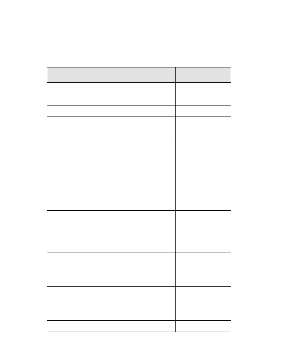
Accessoires en option 1
y
y
g
y
y
g
g
y
g
g
y
Les accessoires optionnels suivants peuvent être utilisés avec l'ardoise Stylistic 3400.
Reportez-vous aux instructions fournies avec ces accessoires pour obtenir des informations
sur leur utilisation.
Périphérique/accessoire
Duplicateur de port S t
Mini station d'accueil St
berceau pour utilisation fréquente Stylistic 3400 FMW42CR1
berceau à monta
Housse portfolio St
Housse Stylistic 3400 FMWCC43
Kit couvre-antenne St
lecteur de disquettes externe FMWFD2
clavier USB (US) FMWKB5A
Clavier infrarou
listic 3400 FMW42PR1
listic 3400 FMW42DS1
e mural Stylistic 3400 FMW42CR3
listic 3400 FMWCC42
listic 3400 FMW42RC1
e (US) FMWKB4A
Numéro de pièce
Fujitsu
(GB) FMWKB5B
(FR) FMWKB5F
(GR) FMWKB5D
(IT) FMWKB5E
(GB) FMWKB4B
(FR) FMWKB4F
(GR) FMWKB4D
Alimentation allume-ci
Attache de st
Support bureau pliant FMWDS3
adaptateur c.c. FMWAC6
Bloc batterie de recha n
Chargeur de batteries externe Stylistic FMW42BC1
Protè
lets Stylistic (lot de 5) FMW42PN1
St
2
Démarrage
let FMWST2
e-écran (lot de 12) FMWSP9
ares FMWCB2
e Stylistic 3400 FMW42BP1
Page 67

Fonctions de l'ard oise Styl istic 34 00 1
j
glag
y
y
g
Les fonctions et les commandes que vous allez utiliser pour faire fonctionner l'ardoise
Stylistic 3400 sont décrites brièvement et illustrées dans les figures 1-1 et 1-2 ci-dessous.
Vous trouverez des détails concernant l'utilisation de ces fonctions et commandes dans la suite
de ce manuel.
Prise
ack pour casque téléphonique
Prise jack pour microphone
Bouton Réinit.
Bouton Suspend/Resume
PCMCIA CardBus/
Connecteur vidéo zoom
Lecteur de disquettes
Port USB (A)
Porte-st
Port IrDA/FIR
Port modem
Events de ventilation
Attache de st
Point de fixation
let
let
Système
Diodes lumineuses
d'état
Fonctions avant / dessus / côté droit : 1
Alimentation en
courant continu
Port vidéo
Microphone
Duplicateur de port
Pavés de ré
ePort clavier infrarouge
Point de verrouilla
e
Figure 1-1 Fonctions de l'ardoise Stylistic 3400 (vue de face)
• Diodes lumineuses d'état du système : elles indiquent l'état opérationnel de l'ardoise et
du disque dur, le niveau de charge de la batterie et l'état du mode hovering.
• Stylet : c'est le principal dispositif de pointage que vous utilisez pour exécuter les
programmes et entrer les données. Un porte-stylet est intégré à l'ardoise pour y ranger le
stylet quand ce dernier n'est pas utilisé.
Fonctions de l'ardoise Stylistic 3400
3
Page 68

• Bouton Suspend/Resume : permet de suspendre et de reprendre l'utilisation du système
afin d'économiser la batterie.
• Prise jack de microphone : permet de connecter un microphone externe.
• Prise jack pour casque téléphonique : permet de connecter un casque téléphonique.
• Connecteur PCMCIA CardBus/vidéo zoom : permet d'installer des cartes PCMCIA
†
dans le système.
• Port IrDA/FIR : fournit une interface infrarouge pour communiquer avec des
périphériques conformes à la version révisée 1.1 de la norme IrDA.
• Port clavier infrarouge : le port infrarouge entoure l'avant et le fond de l'affichage et il
†
sert à communiquer avec une souris ou un clavier infrarouge exclusif.
• Touches rapides : permettent de modifier les caractéristiques de l'affichage et du
haut-parleur en tapant avec le stylet.
• Port USB A : permet de brancher des périphériques de type USB (Universal Serial Bus)
sur l'ardoise. Le port USB B se trouve sur la mini station optionnelle ou sur le duplicateur
†
de port.
• Port modem : permet de brancher un connecteur standard RJ-11 au modem interne à 56
Kb/s de l'ardoise.
Note : Le port de l'élément réseau local du module interne réseau local/modem est
†
disponible sur la mini station optionnelle et/ou le duplicateur de port.
• Connecteur d'entrée d'alimentation en courant continu : permet de connecter
†
l'adaptateur secteur ou l'alimentation allume-cigares.
• Bouton Réinit. : met l'ardoise hors tension en cas de problème syst ème.
• Events de ventilation : assurent le refroidissement secondaire du processeur. (Ne pas
obstruer les évents).
• Point de fixation de l'attache du stylet: permet de fixer une attache de stylet.
• Point de verrouillage du duplicateur de port : permet d'attacher le système à un
†
duplicateur de port ou à une mini station.
• Port de lecteur de disquettes : permet d'attacher un lecteur de disquettes au système.
• Port vidéo : permet de connecter un moniteur vidéo externe au Stylistic 3400.
†
Ces périphériques et accessoires sont vendus séparément.
4
Démarrage
†
†
Page 69

g
Guide du couvercle radio
Couvercle de la mémoire
Batterie
Libération
Bouton
Haut-parleur
1
Couvercle du disque dur
Système
Interface
Connecteur
Contacts métalliques
(Alimentation et USB)
Events de ventilation
Loquet de la batterie
Verrou Kensington
Point de verrouillage du duplicateur de port
Port clavier infrarouge
Bloc batterie
Figure 1-2 Fonctions de l'ardoise Stylistic 3400 (vue arrière)
Caractéristiques ar ri ère / fond / côté
auche : 1
• Connecteur d'interface système : permet de connecter le duplicateur de port Stylistic, la
†
mini station Stylistic ou un autre dispositif d'accueil approuvé.
• Haut-parleur : permet la lecture des fichiers audio sans matériel externe.
• Contacts métalliques : permettent de placer l'ardoise dans une station d'accueil
approuvée pour assurer une connexion haute insertion avec l'alimentation et l'interface
†
USB.
• Bloc batterie amovible : peut être enlevé et chargé dans un chargeur externe optionnel.
Stylet
†
1
• Bouton loquet/libération de la batterie : permet de libérer le bloc batterie amovible.
†
Ces périphériques et accessoires sont vendus séparément.
Fonctions de l'ardoise Stylistic 3400
5
Page 70

• Events de ventilation : assurent le refroidissement secondaire du processeur. (Ne pas
obstruer les évents).
• Point de verrouillage du duplicateur de port : permet d'attacher le système à un
duplicateur de port.
†
• Port clavier infrarouge : le port infrarouge est situé au fond et à l'avant de l'affich age et il
sert à communiquer avec un clavier infrarouge.
†
• Couvercle de mémoire : couvercle démontable qui recouvre les puces de mémoire vive.
• Guide du couvercle radio : fournit des guides d'alignement et des points de verrouillage
pour solution radio de réseau local tiers.
†
• Couvercle du disque dur : recouvre le module du disque dur amovible.
• Fente de verrouillage Kensington™ : permet d'attacher un câble de sécurité compatible
†
à Kensington MicroSaver
†
Ces périphériques et accessoires sont vendus séparément.
TM
.
6
Démarrage
Page 71

Affichag e d'état 1
g
Des témoins apparaissent dans l'affichage d'état et renseignent sur l'état des fonctions
systèmes telles que l'alimentation ou le niveau de charge de la batterie. L'emplacement de
chaque témoin de l'affichage d'état est indiqué à la Figure 1-3.
Hoverin
Batterie
Charge/entrée c.c.
A limentatio n
Figure 1-3 Témoins de l'affichage d'état
Disque dur
Le Tableau 1-1 explique comment sont affichés les divers témoins et décrit ce que signifient
les variations de cet affichage (si un témoin n'est pas affiché, la fonction système
correspondante est désactivée ou inactive).
Affichage d'état
7
Page 72

Note : Dans le tableau ci-dessous, une diode lumineuse "clignotante" est u ne diode qui
g
g
g
g
y
g
g
g
g
g
s'allume une fois par seconde, une diode "clignotante lente" est allumée pendant
une seconde et éteinte pendant cinq secondes.
Tableau 1-1 Témoins d'état du système
Témoin Mode/état
Alimentation
Charge/
entrée c.c.
• Etat Marche
• Mode "Idle"
• Suspend-to-RAM Vert, cli
•état Arrêt
• Sauve
• Etat Marche
• Mode "Idle"
• Suspend-to-RAM
• Sauve
• Etat Arrêt
arde sur disque
arde sur disque
Etat diode
lumineuse
Vert, continu
notant
Arrêt
Oran
e L'adaptateur secteur et le bloc
batterie sont disponibles et le
s
char
Vert • L'adaptateur secteur et le
• L'adaptateur secteur est
Oran
e, clignotant L'adaptateur secteur et le bloc
batterie sont disponibles et le
système attend pour s e mettre
en char
dépassé ses limites
thermiques).
Remarques
stème est en cours de
e.
bloc batterie sont
disponibles et le système
n'est pas en cours de
char
e (la batterie est
complètement char
disponible mais le bloc
batterie n'est pas installé.
e (le bloc batterie a
ée).
Arrêt L'adaptate ur secteur n'es t pas
disponible.
8
Démarrage
Page 73

g
g
g
g
g
g
g
g
Tableau 1-1 Témoins d'état du système
Batterie • Etat Marche
• Mode "Idle"
• Suspend-to-RAM avec
adaptateur secteur
• Save-to-Disk,
avec adaptateur
secteur
•état Arrêt
• Suspend-to-RAM,
sans adaptateur
secteur
• Save-to-Disk,
sans adaptateur
secteur
•état Arrêt
Vert, continu La char
entre 50 et 100 %.
e, continu La charge du bloc batterie est
Oran
entre 13 et 49 %.
e, continu La charge du bloc batterie est
Rou
entre 0 et 12 %.
e, clignotant Une erreur batterie s'est
Rou
produite.
Arrêt Le bloc batterie n'est pas
installé.
Vert, cli
Oran
lent
Rou
lent
Arrêt Si la batterie est insérée
notant lent La charge du bloc batterie est
entre 50 et 100 %.
e, clignotant
e, clignotant
La charge du bloc batterie est
entre 13 et 49 %.
La charge du bloc batterie est
entre 0 et 12 %.
lorsque l'appareil est hors
tension, la diode lumineuse
orange clignote pendant 4
secondes pendant que la
batterie est détectée, après
quoi l'état de la batterie est
affiché pendant 5 secondes.
e du bloc batterie est
Accès au
disque
dur
• Etat Marche
• Mode "Idle"
• Suspend-to-RAM
• Sauve
•état Arrêt
arde sur disque
Vert Affiché pendant un accès au
disque dur.
Arrêt Il ne se prod uit pas d' accès a u
disque dur.
Affichage d'état
9
Page 74

g
g
g
Tableau 1-1 Témoins d'état du système
Hovering • Etat Marche
(Hovering activé)
• Etat Marche
(Hoverin
• Suspend-to-RAM
• Sauve
•état Arrêt
désactivé)
arde sur disque
Vert Le mode hovering est activé.
Arrêt Le mode hoverin
désactivé.
Arrêt
est
10
Démarrage
Page 75

Connecteurs et int erface s périphériques 1
Les connecteurs et les interfaces périphériques de l'ardoise Stylistic 3400 vous permettent de
brancher toute une série de périphériques. La disposition générale des interfaces du système
est illustrée à la Figure 1-4. Les emplacements spécifiques des interfaces sont illustrés à la
Figure 1-5 et à la Figure 1-6.
IrDA Peripherals Phone AC Adapter
IrDA 1.1 RJ-11 2-pin DC-In 2-pin
FDD
External CRT
USB Peripherals
LAN Card
FAX/Modem Card
SCSI Card
SRAM Card
Flash Disk Card
Other
FDD 26-pin
VGA 15-pin
USB 4-pin
CardBus T ype II
68-pin
Metal Contact
8-pin
Port Replicator / Mini-dock / Cradle
Battery Connector
10-pin
Stereo Headphone
Jack 3-pin
Microphone Jack
2-pin
Port Replicator
Interface 200-pin
Figure 1-4 Connecteurs et interfaces périphériques
Battery
Headphones
Microphone
Connecteurs et interfaces périphériques
11
Page 76
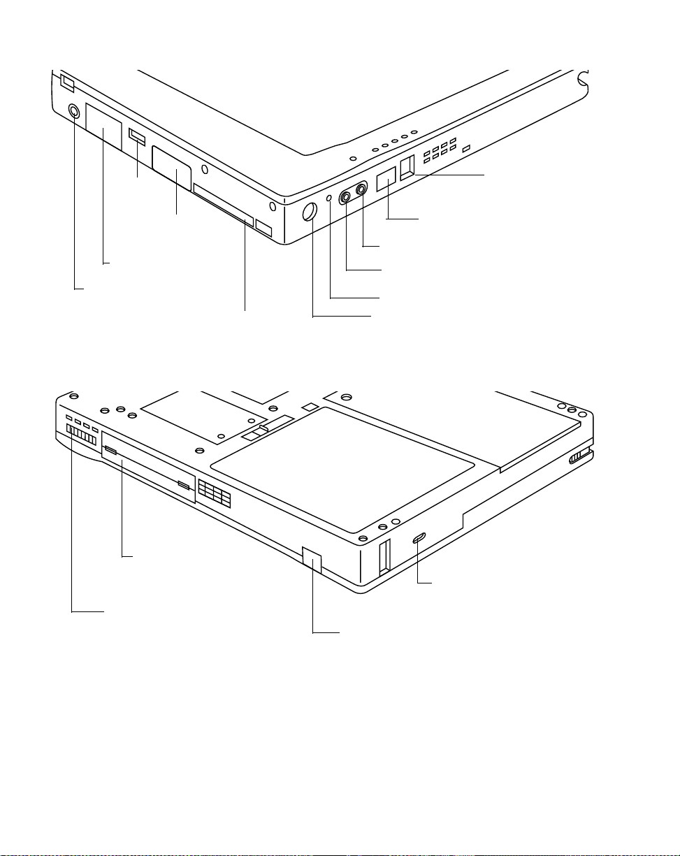
USB (A)
y
port
Port de lecteur
de disquettes
Port vidéo
Alimentation
en courant continu
Connecteur PCMCIA CardBus/vidéo zoo m
Figure 1-5 Connecteurs/interfaces périphériques, dessus et côté droit
S
stème
Interface
Connecteur
Utilisation fréquente
Contacts métalliques
Port modem
Port IrDA/FIR
Prise jack pour casque téléphonique
Prise jack pour microphone
Bouton Réinit.
Bouton suspend/resume
Verrou Kensington
Port clavier infrarouge
Figure 1-6 Connecteurs/interfaces périphériques, fond et côté gauche
12
Démarrage
Page 77
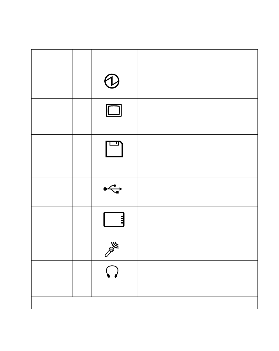
Le Tableau 1-2 décrit chaque connecteur périphérique de l'ardoise Stylistic 3400. Chacune
g
g
g
y
y
y
y
y
des icônes illustrées est reproduite en surimpression sur la housse de l'ardoise.
Tableau 1-2 Connecteurs/interfaces périphériques
Connecteur/
périphérique
Connecteur
d'alimentation
en courant
Fig.
Réf.
Témoin de
l'ardoise
Objet
1-1 Connexion d'une source de courant extérieure
telle que l'adaptateur secteur ou l'alimentation
allume-ci
ares.
continu
Port vidéo
†
1-1 Connexion d'un moniteur vidéo externe. Pour
utiliser le port vid éo, activez l e moniteu r externe à
l'aide de la touche rapid e de sélection d'afficha
(LCD --> Afficha
e externe uniquement -->
Simultané)
Port de lecteur
de disquettes
1-1 Le conne cteur du lecteu r de disquettes utilise une
interface spéciale qui ne s'adapte qu'à un lecteur
de disquettes Fujitsu FMWFD2. N'essa
de relier tout autre t
pe de lecteur à ce
connecteur. Contactez votre revendeur pour plus
d'informations.
Port USB (A) 1-1 Connexion des périphériques de t
(Universal Serial Bus) à l'ardoi se. Le port USB (B)
se trouve sur la mini station d'accueil optionnelle
listic 3400.
St
Connecteur
PCMCIA
CardBus/vidéo
zoom
1-1
Installation d'une carte PCMCIA de t
d'une carte vidéo zoom.
e.
ez pas
pe USB
pe II ou
Prise jack pour
microphone
1-1 Connexion d'un microphone externe. Le
microphone interne est désactivé quand vous
branchez un microphone extérieur.
Prise jack pour
casque
téléphonique
1-1 Connexion d'un casque téléphonique stéréo ou
des haut-parleurs extérieurs alimentés. Le
haut-parleur interne est désactivé quand vous
branchez un casque téléphonique ou des
haut-parleurs extérieurs.
†
Ouvrez la porte connecteurs pour accéder à ces connecteurs.
Connecteurs et interfaces périphériques
13
Page 78

g
g
g
g
y
g
g
g
g
g
g
g
Tableau 1-2 Connecteurs/interfaces périphériques
Connecteur/
périphérique
Fig.
Réf.
Témoin de
l'ardoise
Objet
Port IrDA/FIR 1-1 Un émetteur récepteur infrarouge intégré à
l'ardoise vous permet de communiquer avec
d'autres périphériques conformes à la version 1.1
de la norme IrDA. 1.1. La portée efficace des
communications infrarou
mètre dans un éventail de 15 de
es est d'environ un
rés de part et
d'autre de l'axe. Aucun obstacle ne doit
interrompre le trajet du faisceau infrarou
le port IrDA de l'ardoise et l'émetteur récepteur
IrDA du périphérique.
Modem 1-1 Connexion d'une li
ne téléphonique au modem
interne optionnel à l' aide d'une fiche t éléphonique
RJ-11 standard.
Contacts
métalliques
pour utilisation
fréquente
Port d'interface
†
stème
s
1-2 Installat ion de l'ardoise dans un dispositif
d'accueil approuvé. Les contacts assur ent
l'alimentation en courant continu et l'interface
USB.
1-2 Connexion du duplicateur de port Stylistic 3400
ou d'un autre dispositif d'accueil approuvé.
Reportez-vous à la documentation qui
accompa
ne le dispositif d'accueil pour plus
d'informations.
e entre
Port clavier
infrarou
†
14
1-1,
e
1-2
Un récepteur infrarou
permet de communiquer avec un clavier
infrarou
e sans fil. Le port infrarouge du clavier
fonctionne de manière op tim ale l orsq ue le clavier
se trouve à une distance comprise entre 10 et
30 cm (environ 4 à 12 pouces) du port infr arou
situé sur le bord inférieur de l'ardoise.
Assurez-vous qu'il n'ex is te auc un obs tac le sur le
trajet du faisceau infrarou
infrarou
e de l'ardoise et l'éme tteur inf rarouge du
clavier.
Ouvrez la porte connecteurs pour accéder à ces connecteurs.
Démarrage
e intégré à l'ardoise vous
e
e entre le récepteur
Page 79

g
g
g
y
Tableau 1-2 Connecteurs/interfaces périphériques
Connecteur/
périphérique
Fente de
verrouilla
Kensin
e
ton
†
Ouvrez la porte connecteurs pour accéder à ces connecteurs.
TM
Fig.
Réf.
1-2
Témoin de
l'ardoise
Objet
La fente de sécurité Kensington MicrosaverTM
vous permet de verrouiller l'ardoise à l'aide de
dispositifs de fixation compatibles avec
Kensin
ton.
Outre les témoins des connecteurs et de l'interface, il existe d'autres témoins qui illustrent
l'orientation et les boutons des éléments. Ces témoins sont illustrés au Tableau 1-3..
Tableau 1-3 Autres témoins système
Description des témoins
Batterie Indique l'emplacement du couvercl e de la
Bouton de libération de la
batterie
Illustration
des témoins
Objet
batterie amovible.
Indique le bouton de libération de la
batterie.
Verrou de libération de la
batterie, ouvert
Verrou de libération de la
batterie, fermé
Bouton Suspend/Resume Indique le bouton suspend/resume.
Bouton Réinit. Pas de témoin Met le s
Indique l'emplacement du verrou qui libère
la batterie.
Indique l'emplacement du verrou qui
bloque la batterie.
stème hors tension en cas de
problème.
Connecteurs et interfaces périphériques
15
Page 80

16
Démarrage
Page 81

Chapitre 2
Utilisation de l'ardoise Stylistic 3400
Ce chapitre traite des concepts fondamentaux, des principes de base de fonctionnement et
d'utilisation et des fonctions système de l'ardoise Stylistic 3400 . Vous devez vous fam iliar iser
avec toutes ces informations avant d'essayer de faire fonctionner le système.
Etats système 2
Avant de commencer à utiliser l'ardoise Stylistic 3400, étudiez ses différents états système (ou
modes). Le fait de bien les conn a ître vous permettra de déterminer s'il faut mettre sous tension
ou hors tension le système et suspendre ou reprendre les opérations lorsque vous commencez
une nouvelle session ou que vous terminez la session en cours. Les sections qui suivent
décrivent brièvement le comportement du système pour chaque état, les états étant classés par
ordre décroissant de consommation d'énergie:
• Etat Marche
Le système fonctionne et l'écran est allumé.
• Etat "Idle"
Certaines fonctions système sont limitées ou désactivées afin d'économiser l'énergie.
L'écran d'affichage peut être éteint. Le système revient à l'état Marche quand il détecte une
activité du stylet ou toute autre sollicitation.
• mode Suspend-to-RAM
Le fonctionnement du système est suspendu. La plupart des fonctions système sont
désactivées afin d'économiser l'énergie. La mémoire continue d'être alimentée pour
conserver les données des programmes qui étaient en cours d'exécution lorsque les
opérations ont été suspendues. Le système ne répond pas au stylet ni à d'autres entrées
lorsqu'il se trouve en mode Suspend-to-RAM. Reportez-vous à la section "Reprise des
opérations" dans la suite de ce chapitre pour des instructio ns sur le retour à l'état Marche.
• mode sauvegarde sur disque
Le fonctionnement du système est suspendu. Toutes les fonctions système sont
désactivées afin d'économiser l'énergie. Les données actives des programmes en cours
d'exécution avant la suspension des opérations du système sont stockées sur le disque dur.
Le système ne répond plus au stylet ni aux autres formes d'entrée de données.
Reportez-vous à la section "Reprise des opérations" dans la suite de ce chapitre pour des
instructions sur le retour à l'état Marche.
• Etat Arrêt (éteint)
Toutes les fonctions système sont désactivées afin d'économiser l'énergie. Le système ne
répond plus au stylet ni aux autres formes d'entrée de données. Le système boot lorsqu'il
est remis sous tension.
17
Page 82

Note : Le système consomme la même quantité d'électricité qu'il soit en mode
y
g
g
g
g
y
y
y
g
y
y
Sauvegarder sur disque ou à l'état Arrêt.
Votre système peut être configuré de manière à ce qu'il prenne automatiquement l'un de ces
états après une certaine période d'inactivité pour économiser l'énergie de la batterie.
Lorsque vous devez utiliser l'ardoise Stylistic 3400, vous pouvez modifier l'état actuel du
système de différentes manières, selon l'état dans lequel il se trouve Pour déterminer l'état
actuel du système, regardez le témoin d'alimentation dans l'affichage d'état. Le Tableau 2-1
indique les divers états système représentés par le témoin d'alimentation et il vous indique
comment passer de l'un à l'autre.
Tableau 2-1 Modification des états système
Aspect du témoin
d'alimentation
Témoin d'alimentation
affiché en continu
Témoin d'alimentation
notant
cli
Témoin d'alimentation
non affiché
* Les info rmatio ns co nte nues d ans le Table au 2- 1 son t données pour vous aider à compr endre
dans quels états votre s
procédures de démarra
de son fonctionnement qui sont don nées dans la suite de ce chapitre.
Etat actuel
Etat Marche
ou
Etat "Idle"
Suspend-to-RAM
†
Etat Arrêt
ou Sauve
sur disque
stème peut passer à partir de son état actuel. Reportez-vous aux
e et d'arrêt du système et aux procédures d'interrupti on et de reprise
arder
†
Pour passer à l'état Arrêt, mettez le système
hors tension à l'aide du menu Démarra
Pour passer en mode Suspe nd-to-RAM ou en
mode de sauvegarde sur disque†, suspendez
les opérations en utilisant la commande
suspendre d'un matériel ou d'un logiciel.
Pour passer à l'état Marche, relancez les
opérations en appu
Suspend/Resume.
Pour passer à l'état Arrêt, relancez les
opérations en appu
Suspend/Resume puis arrêtez le s
Pour passer à l'état Marche, mettez en
marche le s
en appu
Pour changer d'état
ant sur le bouton
ant sur le bouton
stème ou relancez les opérations
ant sur le bouton Suspen d/Resum e.
*
e.
stème.
†
Votre système peut être configuré pour utiliser so it le mode Suspend-to -RAM, soit le mode de
arde sur disque.
sauve
18
Utilisation de l'ardoise Stylistic 3400
Page 83

Mise sous tension de l' ardoise 2
Suivez la procédure décrite ci-dessous pour démarrer l'ardoise Stylistic 3400. Avant de
commencer, assurez-vous que le système est à l'état Arrêt. Pour ce faire, observez l'affichage
d'état. Si le témoin d'alimentation n'est pas visible dans l'affichage d'état, le système est à l'état
Arrêt ou en mode Sauvegarder sur disque et vous pouvez appliquer cette procédure. Si le
témoin d'alimentation est visible (soit clignotant, soit allum é en continu), n'exécutez pas cette
procédure. Reportez-vous à la section "Etats système" plus haut dans ce chapitre pour obtenir
une description détaillée des modes de fonctionnement symbolisés par le témoin
d'alimentation.
1. Appuyez sur le bouton Su spend/Resume pour démarrer le système.
2. Assurez-vous que la batterie de votre ardoise est suffisamment chargée ou connectez
l'ardoise à une alimentation extérieure à l'aide de l'adaptateur secteur ou de l'adaptateur
allume-cigares. Reportez-vous à la section "Affichage d'état" du chapitre 1 pour voir
comment déterminer le pourcentage de charge à l'aide du témoin de jauge de la batterie de
la barre d'état.
Une fois que vous avez initialisé le système, celui-ci démarre le système d'exploitation qui est
installé sur le disque dur. Une fois le système d'exploitation lancé, vous pouvez utiliser
l'ardoise.
Mise sous tension de l'ardoise
19
Page 84

Arrêt du système 2
g
Suivez les étapes ci-dessous pour arrêter et mettre hors tension votre ardoise:
1. Si les opérations avaient été suspendues, relancez le système. Reportez-vous à la section
“Reprendre les opérations du système” plus bas dans ce chapitre.
2. Sauvegardez votre travail et fermez tous les programmes en cours d'utilisation.
3. Choisissez Arrêter dans le menu Démarrer de Windows (98, NT Workstation ou 2000) et
appliquez la procédure d'arrêt.
Le système est alors à l'état Arrêt.
Suspension des opérations 2
L'ardoise Stylistic 3400 vous permet de suspendre les opérations système sans fermer les
applications ni quitter le système d'exploitation. Servez-vous de cette fonction pour
économiser la batterie quand il n'est pas pratique d'arrêter le système ou lorsque vous devez
remplacer la batterie.
Pour suspendre les opérations système:
1. Appuyez sur le bouton Suspend/Resume ou activez la commande Interrompre de votre
système d'exploitation ou d'un programme d'économie d'énergie. (Si votre système est
configuré pour suspendre les opérations en passant en mode de sauvegarde sur disque,
expliqué plus loin dans la présente procédure, un message s'affiche pendant que vos
données sont enregistrées sur votre disque dur) .
20
Attention
Si vous devez remplacer le bloc batterie,
système soient suspendues et que le témoin d'alimentation clignote
avant d'enlever le bloc. Si vous ne le faites pas, vous risquez de perdre les
données non enre
istrées.
Selon la configuration de votre système, le témoin d'alimentation clignote
(Suspend-to-RAM) ou il n'est pas affiché (sauvegarde sur disque) lorsque les opérations
système sont suspendues. A ce moment, les programmes en cours d'exécution sont
arrêtés, les données actives sont sauvegardées et le système entre dans l'un des deux
modes à faible consommation d'énergie, ou modes veille, comme il est expliqué dans les
paragraphes qui suivent.
Utilisation de l'ardoise Stylistic 3400
attendez que les opérations
Page 85

2. Observez le témoin d'alimentation de l'affichage d'état pour déterminer le mode veille
utilisé par votre système.
• Le témoin d'alimentation clignote: mode Suspend-to-RAM
Dans ce mode, les données actives sont sauvegardées en maintenant la mémoire
RAM sous tension tandis qu e la plu part des autres éléments du système sont mis hors
tension. Le témoin de jauge de batterie de l'affichage d'état indique le niveau de
charge de la batterie.
• Le témoin d'alimentation n'est pas affiché: mode Sauve ga rder sur disque.
Dans ce mode, les données actives sont mémorisées sur le disque dur et la
consommation d'énergie est la même qu'à l'état Arrêt. Lorsque le système est en
mode Sauvegarde sur disque, le témoin de jauge de batterie n'est pas visible dans
l'affichage d'état. Dans ce mode, il n'y a aucun risque de perte de données en cas
d'interruption de l'alimentation batterie.
Si vous avez effectué correctement cette procédure, les opérations du système sont maintenant
suspendues. Reportez-vous à la section “Reprendre les opérations du système” plus bas dans
ce chapitre pour relancer le système. En outre, notez ce qui suit concernant la suspension des
opérations du système:
• Pour installer un bloc batterie chargé, vous pouvez enlever le bloc batterie en place
lorsque le sy stèm e est en mode Suspend-to-RA M ou en mode sauvegarde s ur disque. Pour
éviter la perte de données n on s auvegardées, attendez que les opérations système aient été
suspendues avant d'enlever le bloc batterie.
• Votre système peut être configuré pour suspendre les opérations automatiquement après
une certaine période d'inactivité.
• Votre système peut être configuré pour passer automatiquement en mode de sauvegarde
sur disque après une certaine période en mode Suspend-to-RAM.
• Le système utilise une petite quantité d'énergie de la batterie quand il est en mode
Suspend-to-RAM. La batterie finira donc par se décharger complètement.
Note : Si vous prévoyez de ne pas utiliser votre ardoise pendant une longue période,
mettez-la hors tension plutôt que d'utiliser le mode Suspend-to-RAM.
• Si la charge du bloc batterie atteint le niveau bas d'alerte (batterie) alors que le système
fonctionne, ce dernier émet des bips par intermittence. Si ceci se produit, suspendez les
opérations, mettez l'ardoise hors tension ou connectez-la à une alimentation extérieure, en
utilisant l'adaptateur secteur par exemple.
• Si la batterie atteint le niveau critique de charge alors que le système fonctionne, ce
dernier bascule d'office dans un mode présélectionné (Suspend-to-RAM ou sauvegarder
sur disque). Si ceci se produit, vous devez installer un bloc batterie chargé ou connectez
l'ardoise à une alimentation extérieure appropriée, l'adaptateur secteur par exemple, avant
Suspension des opérations
21
Page 86

de pouvoir reprendre les opérations système. (Si la batterie atteint le niveau critique de
charge alors que le système est en mode Suspend-to-RAM, le système reste dans ce mode
jusqu'à ce que l'alimentation soit restaurée ou que la charge soit totalement dissipée).
• Le fait de suspendre les o pér a tions interrompt les transmissions de données ; néanmoins,
certains pr ogrammes peu vent empêcher le système de suspendre ses opérations afin de
prévenir un tel type d'interruption.
• L'action du bouton Suspend/Resume peut être désactivée pour éviter une interruption
accidentelle. Si c'est le cas, le fait d'appuyer su r ce bou ton ne s uspen dra pas les opérations
comme décrit ici. (Les opérations ne peuvent alors être suspendues qu'à l'aide du logiciel
système). Contactez le service d'assistance client ou votre revendeur si la configuration de
votre système ne convient pas.
• Si votre ardoise est équipée d'une carte PCMCIA qui vous permet de vous connecter à un
réseau fixe ou hertzien, vous pouvez être déconnecté de ce réseau après une certaine
période d'inactivité lorsque les opérations du système sont suspendues. Contactez
l'administrateur réseau ou le service d'assistance clients pour obtenir des informations
détaillées sur les paramètres de déconnexion de votre réseau.
Reprise des opérations du système 2
Pour reprendre les opérations, que ce soit à partir du mode Suspend-to-RAM ou du mode de
sauvegarde sur disque, appuyez sur le bouton Suspend/Resume.
• A partir du mode Suspend-to-RAM (veille RAM)
Les voyants d'état indiquent que l'état du système se modifie. Vous pouvez devoir attendre
jusqu'à une minute avant que le système revienne à l'état Marche et que les opérations
système reprennent. Notez que l'écran s'allume un peu avant que le stylet ne s'active en
raison des séquences de mise sous tension respectées par le système.
• A partir du mode de sauvegarde sur disque (veille disque)
Les données actives sont lues sur le disque dur et, après quelques secondes, le système
repasse à l'état Marche.
Notez que l'alimentation de plusieurs éléments du système doit être restaurée avant la
reprise des opérations. Laissez aux opérations le temps de reprendre avant d'essayer
d'utiliser l'ardoise. Si votre système est en mode de sauvegarde sur disque, les opérations
mettront un peu plus longtemps à reprendre que s'il est en mode Suspend-to-RAM. Ce
délai supplémentaire est nécessaire pour lire les données à partir du disque dur.
• Utilisez l'ardoise de la façon habituelle une fois que les opérations du système ont repris.
Tous les programmes reprennent au point où ils en étaient l ors de la sus pension des
opérations.
22
Utilisation de l'ardoise Stylistic 3400
Page 87

Utilisation des touches rapides 2
g
Les touches rapide s sont des zones sensibles au stylet situées en dessous de l'affichage
système qui servent à régler les paramètres de l'affichage et du haut-parleur pendant que le
système fonctionne. D'autres touches rapides permettent d'utiliser la fonction bouton droit de
la souris et le mode hovering du stylet.
Pour utiliser une touche rapide, tapez dessus avec le stylet. Vous pouvez également maintenir
appuyée la pointe du stylet contre les touches Volume et Luminosité pour répéter
automatiquement la fonction de la touche. L'emplacemen t de chaq ue tou che rapide est indiqué
à la Figure 2-1.
Programmable Haut-parleur
Témoin
Marche/Arrêt
Volume
Bas
Volume
Haut
Affichage
Sélectionner
Luminosité
(8 niveaux)
Figure 2-1 Touches rapides
Vous trouverez ci-dessous un résumé de la fonction de chaque touch e rapide.
• Touche programmable
Cette touche rapide peut être program mée pour des fonctions spécifiques de l'application.
Contactez votre service d'assistance clients ou votre revendeur si vous avez besoin d'aide
pour utiliser la touche rapide programmable.
• Touches de réglage de volume
Ces touches rapides permettent de régler le volume du haut-parleur ou du casque
téléphonique de l'ardoise si vous vous en servez. (Notez que le haut-parleur interne est
désactivé lorsqu'un casque téléphonique est branch é).
Droit
Souris
Stylet
Hoverin
• Touche rapide marche/arrêt du haut-parleur
Cette touche rapide allume ou éteint le haut-parleur ou le casque téléphonique de l'ardo ise.
Le système émet un bip lorsque vous tapez sur cette touche pour mettre en marche le
haut-parleur ou le casque téléphonique.
Utilisation des touches rapides
23
Page 88

• Touche de sélection écran
g
g
ç
Cette touche rapide vous permet de sélectionner l'aff ichage par l'écran de l'ardoise, par un
moniteur vidéo externe ou par les deux systèmes. L'écran de l'ardoise est vide si vous
sélectionnez un moniteur externe seul.
• Touches rapides de luminosité
Ces touches vous permette nt de régler la luminosité de l'affichage. La luminosité peut être
réglée selon huit niveaux.
• Touche rapide bouton droit de la souris
Cette touche sert à changer la fonction du stylet de l'émulation du bouton gauche de la
souris à l'émulation du bouton droit. Pour effectuer un clic unique de bouton droit de la
souris, tapez une fois sur la touche puis une fois sur l'affichage. Pour effectuer un double
clic de bouton droit de la souris, tapez une fois sur la touche puis deux fois sur l'affichage.
• Touche hovering du stylet
Cette touche active et désactive le mode hovering. Lorsque ce mode est actif, le témoin
d'état Hovering est allumé. Le mode hovering du stylet assure un meille ur contrôle du
curseur. Lorsque l'option hovering est sélectionnée, le curseur peut être placé sur une
icône sans l'activer. Ceci est utile si vous voulez lire un message contextuel associé à une
icône, simuler le déplacement de la souris, sélectionner une petite icône ou commencer
une session peinture.
Utilisation du stylet 2
Vous pouvez utiliser le stylet Styl is t ic 34 00 pou r générer et capturer de "l'encre" électronique,
pour sélectionner des objets et pour naviguer dans les programmes de l'ardoise. Le stylet peut
être utilisé comme une souris à deux boutons conjointement avec la touche rapide d'émulation
du bouton droit de la souris. Les applications qui comportent des fonctions de reconnaissance
de l'écriture vous permettent d'écrire directement sur l'écran avec le stylet. Elles traduisent
ensuite ce que vous avez écrit en texte de style clavier.
Attention
• Assurez-vous que l'écran de l'ardoise porte un
protè
e-écran avant d'utiliser le stylet. La garantie ne
s'applique pas aux rayures d'un écran dépourvu de
protè
e-écran.
• N'utilisez que le stylet fourni avec l'ardoise. N'utilisez pas
d'autres produits qui n'ont pas été con
3400.
us pour le Stylistic
Pour basculer entre l'utilisation du stylet comme instrument d'écriture et comme souris,
cliquez sur la petite icône en forme de stylet dans le plateau système en bas à droite de l'écran.
24
Utilisation de l'ardoise Stylistic 3400
Page 89

Vous trouverez ci-après quelques conseils pour utiliser le stylet comme la souris à deux
y
boutons d'un ordinateur de bureau.
• Pour sélectionner un objet, tapez une fois avec la pointe du stylet sur l'objet en question.
Ceci a le même effet que de cliquez une fois avec le bouton gauche de la souris.
• Pour double-cliquer sur un objet, tapez deux fois rapidement sur l'objet choisi.
• Pour "cliquer une fois avec le bouton droit de la souris", tapez une fois sur la touche,
puis une fois sur l'affichage. Pour "double-cliquer avec le bouton droit de la souris",
tapez une fois sur la touche, puis deux fois sur l'affichage.
• Pour déplacer ou "faire glisser" un objet sur l'écran, placez la pointe du stylet
directement sur l'objet puis déplacez le stylet en maintenant la pointe au con tact de l'écran.
Etalonnage du styl et 2
L'étalonnage du stylet permet de régler la position du curseur sur l'écran par rapport à la
position de la pointe du stylet. Cette opération permet de réduire l'erreur de distance entre
l'endroit où le stylet touche réellement l'écran et l'endroit où le système "pense" qu'il se
trouve. Si l'objet que vous vo ulez appel er ne s 'affi che pas so us l a poi nte du st ylet lorsq ue vo us
utilisez ce dernier, vous devez étalonner le stylet.
L'étalonnage du stylet peut être nécessaire dans les situations suivantes :
• Le stylet est utilisé pour la première fois.
• L'utilisateur précédent de la tablette Stylistic 3400 écrit de l'autre main ou tient le stylet
sous un angle différent.
• L'ardoise a été utilisée pendant un certain temps sans que le stylet soit ré-étalonné.
• L'image du système d'origine a été restaurée.
Pour étalonner le st
1. Ouvrez le panneau de configuration dans le menu Démarrer/Paramètres et double-tapez
sur l'icône stylet. Sélectionnez le fichier de propriétés Etalonnage, puis cliquez sur
Etalonnage du stylet.
2. Placez l'ardoise Stylistic 3400 comme vous le faites habituellement quand vous l'utilisez.
Assurez-vous que vous tenez le s t ylet avec le même angle que d'habitude. T o uchez l'écran
uniquement avec la pointe du stylet: l'étalonnage peut être erroné si vous touchez l'écran
du doigt ou de la main au cours de cette procédure.
let: 2
Utilisation du stylet
25
Page 90

3. Réalisez l'étalonnage en suivant les instructions qui apparaissent à l'écran. L'utilitaire
d'étalonnage affiche une cible successivement dans chacun des qu atre coin s de l'écran. En
tenant toujours le styl et comme vous le faites normalement, t apez de manière aus si précise
que possible sur le centre de chaque cible qui s'affiche.
Une boîte de dialogue apparaît lorsque vous avez tapé sur la dernière des quatre cibles.
T ap ez sur l'écran dans le s 20 s econ des qu i sui v ent s i vou s v oul ez en regis t rer le s no uveau x
paramètres d'étalonnage. Si vous ne le faites p a s, les paramètres d'étalonnage par défaut
seront utilisés.
4. Lorsque la fenêtre Vérification des nouveaux paramètres d'étalonnage du stylet apparaît,
sélectionnez l'une des options suivantes.
• Si vous estimez avoir tapé précisément sur le centre des cibles, tapez sur Oui.
L'étalonnage que vous avez effectué à l'étape 3 est accepté.
• Si vous ne voulez pas conserver le nouvel étalonnage, tapez sur Non.
• Si vous voulez refaire l'étalonnage, tapez sur Recalibrate. Les instructions
d'étalonnage sont alors affichées de nouveau.
Si vous avez réussi à exécuter la procédure décrite ci-dessus, votre stylet est étalonné et vous
pouvez vous en servir de la manière habituelle.
Remplacement du stylet 2
A l'usage, la pointe du stylet peut s'user ou amasser des particules abrasives qui peuvent rayer
l'écran. Une pointe endommagée ou tordue risque de ne pas se déplacer librement et
l'utilisation du stylet peut avoir alors des résultats im prévisibles. Si votre stylet exhibe ce
genre de problèmes, il faut le remplacer en contactant votre revendeur.
Chargement du bl oc bat terie 2
Le bloc batterie du Stylistic 3400 peut être chargé pendant qu' il est inst all é dans l'ardoise.
Pour ce faire:
1. Connectez une source d'alimentation en courant continu, l'adaptateur secteur p ar exemple,
au connecteur d'entrée en courant continu de l'ardoise. Le témoin Entrée c.c. apparaît dans
l'affichage d'état. Si le niveau de charge de la batterie est inférieur à 90 %, la batterie se
26
Utilisation de l'ardoise Stylistic 3400
Page 91
met en charge et le témoin de chargement apparaît dans l'affichage d'état. Si le niveau de
charge est supérieur ou égal à 90 % lorsque vous connectez la source d'alimentation en
courant continu, la batterie ne se met pas en charge, ce qui évite les surcharges.
2. Observez le témoin de jauge de la batterie dans l'affichage d'état pour connaître le
pourcentage de charge approximatif de la batterie. Reportez-vous à la section "Témoins
d'état" du chapitre 1 de ce manuel qui décrit le témoin de jauge de la batterie.
Tant que l'alimentation en courant continu reste connectée à l'ardoise, la charge se poursuit
jusqu'à ce que le niveau de charge de la batterie atteigne 100 %. Les temps de charge qui sont
indiqués au Tableau 2-2 correspondent à la charge d'une batterie complètement vide qui se
recharge soit quand l'ardoise fonctionne, soit quand elle ne fonctionne pas.
Tableau 2-2 Temps de charge de la batterie
Charge du bloc batterie
Niveau atteint
90 % 3 heures 6 heures*
100 % 4 heures 8 heures*
Temps de charge
approximatif
(l'ardoise ne fonctionne pas)
Temps de charge
approximatif
(l'ardoise fonctionne)
* En fonction des applications utilisées.
Veuillez également faire attention aux points suivants lorsque vous chargez la batterie:
• Vous pouvez utiliser le système, susp endre les opérations ou arrêter et mettre l'ardois e
hors tension sans suspendre la charge de la batterie ; cependant, l'utilisation de l'ardoise
alors que la batterie est en charge ralentit le rythme de la charge, comme le fait apparaître
le Tableau 2-2.
• Comme indiqué dans la proc édure ci-dessus, le système ne met pas la batterie en charge si
le niveau de charge est supérieur ou égal à 90 % au moment où l'ardoise est connectée à
une source d'alimentation externe (ceci afin d'éviter les surcharges).
• Le bloc batterie Stylistic 3400 utilise des éléments au lithium-ion qui n'ont pas “d'effet
mémoire”. V ous n'avez donc pas besoin de décharger complètement la batterie avant de la
mettre en charge.
Extraction et installation du bloc batterie 2
Le bloc batterie peut être retiré de l'ardoise et remplacé par une batterie chargée. La batterie
vide peut alors être rechargée à l'aide d'un chargeur externe, si vous en avec un. Pour retirer le
bloc batterie de l'ardoise:
Extraction et installation du bloc batterie
27
Page 92

1. Choisissez l'une des options suivantes:
• Si vous disposez d'un bloc batterie chargé, vous pouvez suspendre les opérations du
système. Une batterie "en pont" intégrée maintient le système en mode
Suspend-to-RAM pendant environ 5 minutes lorsque le bloc batterie est enlevé, ce
qui permet de le remplacer par un bloc batterie chargé.
• Si vous ne disposez pas de bloc batterie chargé, enregistrez votre travail et fermez
tous les programmes actifs, puis arrêtez le système ou passez en mode de sauv egarde
sur disque.
• Connectez une source extérieure d'alimentation en courant continu.
2. Appuyez et maintenez enfoncé le bouton de libération de la batterie. (voir la Figure 2-2).
3. Tout en maintenant le bouton, faites glisser le verrou de libération de la batterie dans la
direction indiquée à la Figure 2-2. Le bord du bloc batterie se soulève de la surface de
l'ardoise.
4. Retirez le bloc batterie de l'ardoise.
Si vous utilisez un chargeur de batterie externe, reportez-vous aux instructions d'utilisation
fournies avec cet appareil.
Pour installer le bloc batterie:
1. Orientez la batterie de manière à ce que son connecteur soit placé sur le connecteur du
plateau de batterie vide. Placez le bloc batterie dans le plateau et enfoncez-le fermement
jusqu'à ce qu'il s'enclenche. Lorsque le bloc batterie est correctement placé, le verrou de
libération do it se déplacer vers le bouton de libération.
2. Lorsque la batterie est fermement en place, appuyez sur le verrou de libération de la
batterie en direction du bouton de libération jusqu'à ce que ce dernier se soulève jusqu'au
niveau de l'ardoise.
Le bloc batterie une fois installé, vous pouvez reprendre les opérations du système et l'utiliser
de la manière habitu elle.
28
Utilisation de l'ardoise Stylistic 3400
Page 93

Verrou de libération
de la batterie
Couvercle
de batterie
Bouton de libération de la batterie
Figure 2-2 Enlever le bloc batterie
Conseils de réduction de la consommati on de l 'énergie de la
batterie 2
Vous pouvez prolonger la durée de vie de votre batterie en réduisant la consommation
d'énergie. En utilisation normale, un bloc batterie entièrement chargé peut faire fonctionner le
système pendant 2,5 heures environ avec la plupart des applications*. Cette durée peut varier
en fonction des applications que vous faites tourner et de la configuration du système. Voici
quelques su ggestions qui vous permettront d'économiser l'énergie de votre batterie:
• dans la mesure du possible, utilisez une source d'alimentation extérieure telle que
l'adaptateur secteur pour alimenter le système,
• suspendez les opérations système si vous envisagez de ne pas utiliser votre système
pendant quelques minutes,
•éteignez l'ardoise si vous ne devez pas l'utiliser pendant une période plus longue,
• et utilisez des temporisateurs de gestion d'énergie (disponibles avec la configuration
BIOS) qui vous aideront à économiser l'énergie de façon automatique. Contactez votre
revendeur avant de modifier le BIOS.
* La durée de vie de la batterie dépend de divers facteurs: système d'exploitation,
paramètres d'alimentation et applications utilisées.
Conseils de réducti on de la conso mm ati on de l'énergie de la batterie
29
Page 94

Utilisation de la batterie en pont
Lorsqu'il est installé dans l'ardoise, le bloc batterie alimente certains éléments du système,
même lorsque celui-ci est à l'état Arrêt. Lorsque le bloc batterie est enlevé, ces éléments sont
alimentés par une batterie "en pont" intégrée à l'ardoise.
La batterie en pont n'est pas conçue pour une utilisation prolongée. Pour l'entretenir
convenablement, respectez les mesures suivantes:
Note : L'ardoise est livrée avec une batterie en pont déchargée.
• Pour éviter de décharger la batterie en pont, stockez toujours l'ardoise avec un bloc
batterie chargé.
• Si la batterie en pont se décharge complètement, il faut environ 11 heures pour qu'elle se
recharge à fond.
• La batterie en pont se charge lorsque l'adaptateur secteur est connecté et que le système est
à l'état Marche ou Arrêt ou en mode Suspend. Elle se charge à partir de la batterie
seulement lorsque le système est à l'état Marche.
Connexion du modem 2
Note: • La vitesse de transfert maximale réelle du module interne modem/réseau local
de 56 kb/s installé dans l'ardoise Stylistic 3400 est de 53 kb/s (réception), 33,6
kb/s (émission) et 14,4 kb/s (télécopie). La FCC limite la vitesse de
téléchargement à 53 kb/s aux Etats-Unis.
• La partie réseau local du module ne peut être utilisée que lorsque l'ardoise est
installée dans la mini station d'accueil ou le duplicateur de port. Il n'existe pas
de port pour réseau local sur l'ardoise elle-même.
L'ardoise Stylistic 3400 est conçue pour accepter une fiche téléphonique RJ-11 standard.
Connectez la fiche à la prise jack du modem située sur l'ardoise, à gauche du port IrDA (voir
la Figure 1-1). La fiche téléphonique peut être installée que l'ardoise soit sous tension ou non.
Si vous avez besoin d'aide pour configurer le modem ou le réseau local de l'ardoise Stylistic
3400, contactez votre service d'assistance clients ou votre revendeur.
30
Utilisation de l'ardoise Stylistic 3400
Page 95

Connecteur de car te PCMCI A 2
Le connecteur de carte PCMCIA de l'ardoise Stylistic 3400 vous permet d'installer une carte
CardBus PCMCIA de Type II.
Pour installer une carte PCMCIA, placez vers le haut le côté qui porte une flèche (la flèche de
la carte doit être visible lorsque vous regardez l'ardoise du côté écran). Faites glisser la carte
dans le connecteur de carte PCMCIA et enfoncez-la fermement pour qu'elle s'enclenche bien.
Pour installer une carte PCMCIA radio, reportez-vous à la documentation qui accompagne le
kit de couvercle d'antenne (FMW42RC1). Ce kit est conçu pour recouvrir et protéger
l'antenne radio.
Si vous avez besoin d'aide pour installer une carte PCMCIA dans votre ardoise Stylistic 3400,
contactez votre service d'assistance clients ou le revendeur.
Connecteur de carte PCMCIA
31
Page 96

32
Utilisation de l'ardoise Stylistic 3400
Page 97

Chapitre 3
g
g
g
Entretien et Maintenance
Ce chapitre vous donne des conseils sur l'entretien et la maintenance de votre ardoise Stylistic
3400.
Protection de l 'écran 3
L'ardoise Stylistic 3400 est conçue pour vous donner satisfaction pendant de longues années.
L'utilisation d'un protège-écran va vous aider à garder un écran aussi clair que possible. Une
fois installé, le protège-écran constitue une surface d'écriture durable, remplaçab le et an tireflet
qui protège l'écran de toute rayure.
Pour obtenir des protège-écrans de remplacement, commandez la pièce Fujitsu numéro
FMWSP9 (lot de 12 unités). Des informations supplémentaires sur l'installation des
protège-écrans se trouvent dans la notice qui les accompagne.
Attention
Au cours de l'utilisation normale de l'ardoise, de petites
particules provenant de l'environnement extérieur peuvent se
loger dans la pointe du stylet et rayer l'écran. Pour l'éviter,
assurez-vous qu'un protè
votre ardoise. La
écran dépourvu de protè
arantie ne s'applique pas aux rayures d'un
e-écran est installé avant d'utiliser
e-écran.
Pour installer un nouveau protège-écran sur votre ardoise:
1. si un protège-écran était déjà en place, retirez-le avant d'installer le nouveau.
Le protège-écran est maintenu en place sur la surface de l'écran par une mince bande
adhésive le long des bords. Une encoche dans l'un des coins du protège-écran vous permet
de glisser votre ongle dessous pour le retirer plus facilement.
2. Nettoyez l'écran en frottant doucement sa surface avec un chif fon do ux en co ton imprégné
d'alcool isopropyli que. Assu rez-vous q u'il ne reste pas de fil m sur l'écran avant d'appliquer
le nouveau protège-écran.
33
Page 98

y
g
Attention
L'ardoise Stylistic 3400
et ne la netto
ez pas avec un chiffon détrempé.
n'est pas étanche
. Ne la moui llez pa s
3. Retirez d'abord le film protecteur de la face adhésive du nouveau protège-écran.
4. Appli quez le protège-écran sur la surface de l'écran. Ce faisant, orientez-le avec la face
adhésive vers l'écran et l'encoche dans le coin inférieur gauche de l'écran.
5. Appuyez sur le protège-écran avec vos doigts en faisant des mouvements circulaires
le long des bords. L'adhésif prend complètement en 48 heures. Pour assurer un bon
contact entre le protège-écran et l'écran, ne soulevez pas le protège-écran une fois qu'il a
été appliqué.
6. Retirez le film protecteur plastique de l'autre côté du protège-écran.
7. Eliminez tous les résidus qui ont pu rester sur le protège-écr an en frottant doucement sa
surface avec un tissu doux en coton légèrement imprégné d'alcool isopropylique. Essuyez
ensuite le protège-écran avec un chiffon doux sec pour retirer toute trace d'adhésif: cette
précaution évitera au stylet de grincer.
Votre protège-écran est maintenant installé.
Stockage de l'ardoi se Stylist ic 34 00 3
Attention
Prenez soin de ne pas stocker votre Stylistic 3400 en le
posant sur l'écran, ce qui risquerait de détériorer l'afficha
e.
Stockez l'ardoise Stylistic 3400 à l'état Arrêt et après avoir vérifié qu'elle comporte un bloc
batterie complètement chargé. Le bloc batterie du Stylistic 3400 alimente en électricité
certains éléments du syst ème même lorsque celui-ci est à l'état Arrêt. Si le système est stocké
sans le bloc batterie, ces éléments sont alimentés par la batterie en pont interne du système. La
batterie en pont n'est pas conçue pour une utilisation prolongée et elle se déchargera en très
peu de temps, ce qui peut la détériorer. Vous pouvez stocker l'ardoise à l'état Arrêt pendant
environ 30 jours avec un bloc batterie complètement chargé. Au bout de cette période, la
batterie doit être rechargée ou remplacée par une batterie chargée.
34
Entretien et Maintenance
Page 99

Eviter la surchauffe 3
y
L'ardoise Stylistic 3400 surveille sa température interne. Lorsque cette dernière s'appro che de
la limite maximale supportable par les éléments sensibles à la chaleur, les fonctions du
système sont automatiquement limitées ou désactivées pour éviter toute détérioration.
Pour éviter la surchauffe, n'obstruez pas les évents qui se trouvent sur l'ardoise et le long de
ses bords inférieurs.
Nettoyage de l'écran 3
Pour nettoyer l'écran de l'ardoise, essuyez doucement sa surface avec un chiffon doux en
coton légèrement humecté d'eau ou d'alcool isopropylique.
Attention
L'ardoise Stylistic 3400
et ne la netto
ez pas avec un chiffon détrempé.
n'est pas étanche
. Ne la moui llez pa s
Eviter la surchauffe
35
Page 100

Dépann ag e 3
Les sections qui suivent décrivent les solutions à certains problèmes courants. Si votre ardoise
Stylistic 3400 présente un problème qu e vous n'arrivez pas à résoudre en exécutant les actions
décrites, contacter votre service d'assistance clients ou votre revendeur pour obtenir de l'aide.
L'ardoise est bl o quée en mode veille 3
Si l'ardoise ne reprend pas les opérations après qu'elles ont été suspendues, vérifiez les points
suivants:
• Le bloc batterie peut être défectueux ou avoir atteint son niveau bas de charge critique.
Quand ce niveau est atteint, l'ardoise se met d'office en mode Suspend-to-RAM pour
éviter une perte totale d'alimentation. Pour corriger ce problème, connectez une
alimentation externe (l'adaptateur secteur par exemple) ou installez un bloc batterie
chargé.
• Le système peut avoir atteint sa température critique. Pour év iter que soient endommagés
les éléments sensibles à la chaleur, le système se met en mode Suspend-to-RAM quand la
température est trop élevée. Les opérations ne reprendront que lorsque la température sera
redescendue dans des limites acceptables. Placez l'ardoise dans un endroit plus frais.
L'écran est vide ou illisible 3
Si l'écran de votre ardoise Stylistic 3400 est vide ou illisible, assurez-vous que le système
fonctionne (le témoin lumineux d'alimentation est affiché en continu dans l'affichage d'état) et
vérifiez les points suivants:
• La luminosité peut être réglée à un niveau trop faible, ce qui rend l'écran presque noir.
Utilisez la touche de réglage de luminosité pour ajuster ce paramètre.
• Il se peut qu'un moniteur externe ait été sélectionné. Tapez sur la touche Sélection écran
pour vérifier si l'écran de l'ardoise est bien sélectionné.
• La temporisation vidéo peut avoir expiré. Tapez sur l'écran pour le réactiver. Notez qu'il
s'agit ici d'une fonction normale qui permet d'économiser de l'énergie.
Le curseur ne suit pas le stylet 3
Si le curseur à l'écran ne suit pas exactement le stylet ou s'il semble ne pas être correctement
aligné avec lui, étalonnez le stylet. Reportez-vous à la procédure "Etalonnage du stylet"
décrite au chapitre 2.
36
Entretien et Maintenance
 Loading...