

Page 1
Series HMI Connection Manual
Siemens S7 300 (ISO TCP)
HMI Factory Setting:
IP Address: 192.168.0.1
COM Port: 102
Control Area / Status Area: DBW0 / DBW20
Connection
Standard Jumper Cable / Network Cable without jumper (Auto-detected by HMI)
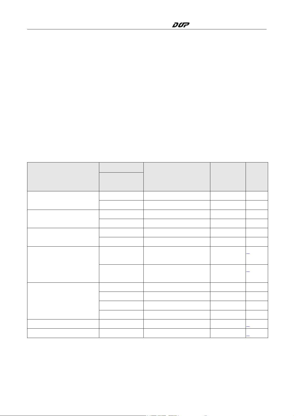
Definition of PLC Read/Write Address
a. Registers
Format
Type
Input Image
Output Image
Internal Bits
Data Area
Data Area (DB10)
Word No.(n)
Bank No.(m)
IWn IW0 – IW65534 Word
IDn ID0 – ID65532 Double Word
QWn QW0 – QW65534 Word
QDn QD0 – QD65532 Double Word
MWn MW0 – MW65534 Word
MDn MD0 – MD65532 Double Word
DBm.DBWn DB1.DBW0 –
DBm.DBDn DB1.DBD0 –
DBWn DBW0 – DBW65534 Word
DBDn DBD0 – DBD65532 Double Word
VWn VW0 – VW65534 Word
VDn VD0 – VD65532 Double Word
Read/Write Range Data Length Note
Word 1
DB255.DBW65534
Double Word
DB255.DBW65532
1
Timer Tn T0 – T65535 Word 2
Counter
V1.02 Revision January, 2012 203
Cn C0 – C65535 Double Word
3
Page 2
Series HMI Connection Manual
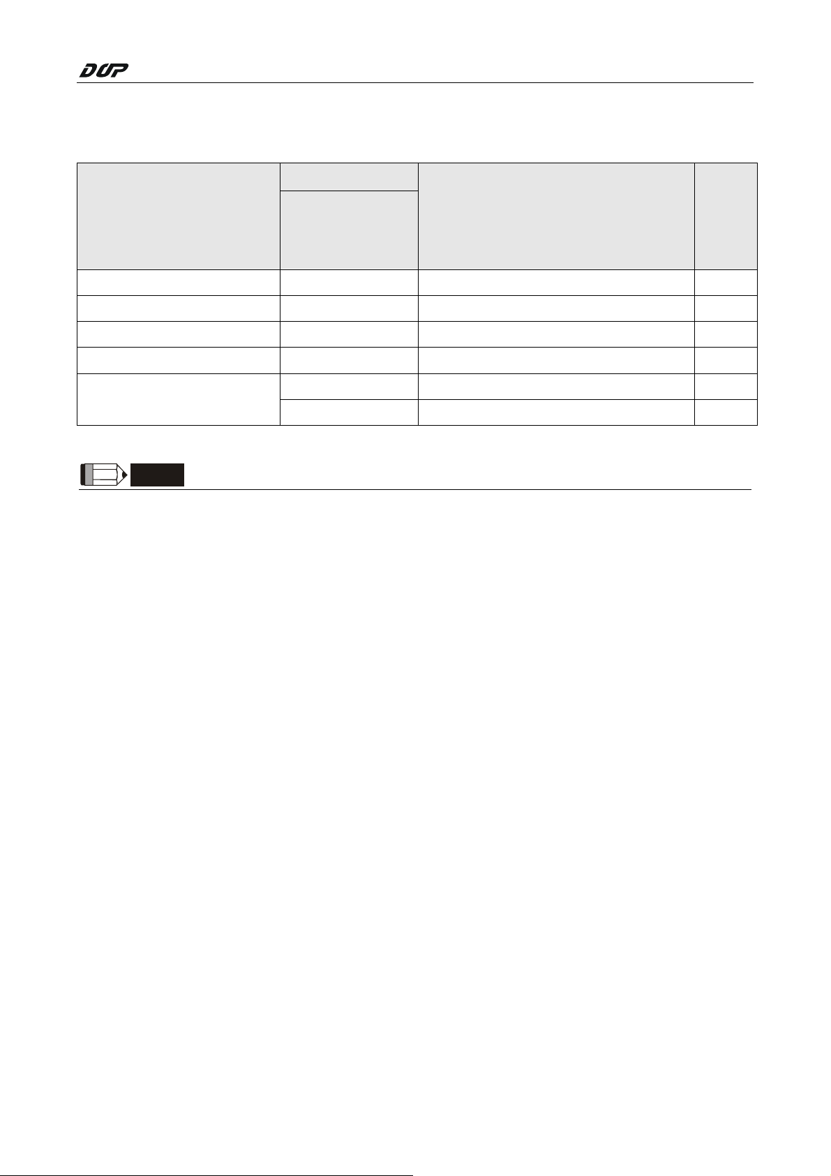
b. Contacts
Format
Type
Input Image In.b I0.0 - I65535.7
Output Image Qn.b Q0.0 - Q65535.7
Internal Bits Mn.b M0.0 - M65535.7
Data Area DBm.DBXn.b DB1.DBX0.0 – DB255.DBX65535.7
Data Area (DB10)
NOTE
1) PLC needs to enable DB memory (DBm.DBWn、DBm.DBDn、DBm.DBXn.b) before DB data
Word No.(n)
Bank No.(m)
Bit No.(b)
DBXn.b DBX0.0 – DBX65535.7
Vn.b V0.0 – V65535.7
Read/Write Range Note
can be read.
2) Timer reads only up to 3 digits. If a value input is more than 3 digits, the Timer will
regards the highest 3 (decimal) and replace the rest by 0. For example, a value 12345
will be written as 12300 in PLC.
3) Counter reads only up to 3 digits. If a value input is more than 3 digits, the Counter will
regards the first 3 digits and leave out the rest. For example, a value 12345 will be
written as 123 in PLC.
4) Except register Tn and Cn,data type of register is Byte and its order is opposite to usual
controller , for example :
1、 IW3 is a word which combined from IB3 and IB4,High Byte of IW3 is IB3;Low Byte of
IW3 is IB4.
2、 ID3 is Double Word which combined from IB3, IB4, IB5 and IB6, and its order from
highest to lowest is IB3, IB4, IB5 andIB6.
And please be attentive to use these registers, because their Data type is different with
Data Length, it will need more than one register for each access, for example:
1、 AIW6 which Data Type is Byte and Data Length is 1 Word, when it used for one word
Numeric Entry , it will occupy two addresses AIB6 and AIB7。
204 V1.02 Revision January, 2012
Page 3

Series HMI Connection Manual
2、 MD12 which Data Type is Byte and Data Length is Double Word,when it used for one
word Numeric Entry, it will occupy four addresses MB12,MB13,MB14 and MB15; But
data only stored in MB14 and MB15.
3、 IW3 which Data Type is Byte and Data Length is 1 Word , when it used for double word
Numeric Entry, it will occupy for addresses IB3,IB4,IB5 and IB6,order from highest to
lowest byte is IB5,IB6,IB3 和 IB4.
V1.02 Revision January, 2012 205
Page 4

Series HMI Connection Manual
Settings
Screen Editor:
1. HMI Ethernet Setting
206 V1.02 Revision January, 2012
Page 5

2. PLC Ethernet Setting
Series HMI Connection Manual
Simatic (V5.4):
1. Right click on “CP343-1 Lean” module and select "Object Properties", on this page set up “IP
address” and “Subnet mask” for CP343-1 Lean Module. Please be aware that the “IP
address” setting must be the same as PLC Ethernet setting in Screen Editor and the “Subnet
mask” setting must be the same as the HMI Ethernet setting in Screen Editor.
2. To add a new "Other station", right click on “Object Properties", add a new Interface and set
the “Type” as “Industrial Ethernet”. To set up HMI “IP address” and “Subnet mask”, go to
“Ethernet interface" > "Properties", please be aware that this setting must be the same as the
HMI Ethernet setting in Screen Editor. As the setting is completed, left click on the green box
above “Other station” and drag to link with the green line above.
V1.02 Revision January, 2012 207
Page 6

Series HMI Connection Manual
3. Right click on the CPU module and select "Insert New Connection", for “Connection Partner”
select “Unspecified” and for “Type” select “TCP connection”. Then go to "Properties - TCP
connection" >"Options", and set “Mode” to “Fetch passive”; please follows the restriction for
“Address” setting, set “Address” to Local Port No. must be the same as PLC Ethernet setting
in Screen Editor, to Partner’s IP must be the same as HMI Ethernet setting in Screen Editor,
but Port No. can be any Port No. depending on the structure of network connection.
4. Right click on another CPU to add a new “TCP connection” and repeats setting 3, except the
“Mode”, go to “Options” > “Mode” and select “Write passive”.
5. After setting 1~4 is done, you will see two “TCP connection” at the bottom of PLC Ethernet
setting page. PLC Ethernet setting is completed.
6. For detail on parameter setting, please refer to Siemens PLC user manual.
HSA
208 V1.02 Revision January, 2012
 Loading...