FUJITSU 240R Service Manual

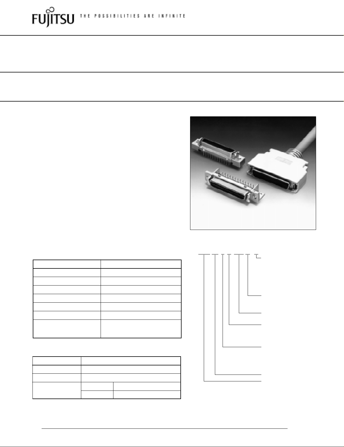
FOR BOARD-TO-CABLE CONNECTION

240R SERIES

FEATURES

1.27 mm (0.050 in.) pitch contact arrangement enables high-density mounting.

Bellows contacts ensure stable contact preventing pins from bending. The bellows contacts also have excellent stability with repeated insertion and extraction.

Cables and connectors are assembled by discrete wire IDC.

Connectors on the cable side provide superb EMI shielding/ESD protection with an inner-metal and outer-plastic dual cover.

Conforms to IEEE 1284.C Interface

Tails are spaced in a four-row staggered arrangement (2.54 mm × 1.905 mm) (0.100 in. × 0.075 in.) for easy

PC board design.


ORDERING CODE

SPECIFICATIONS


FCN-24 5 D 050-G / E


Item


Specifications


Operating temperature range


–55°C to +85°C


Current rating


DC 1 A


Voltage rating


AC 240 V


Contact resistance


50 mΩ max. (DC 20 mV, 10 mA)


Insulation resistance


1,000 MΩ min. (DC 500 V)


Dielectric withstand voltage


AC 750 V for 1 minute


AWG #28 and #30 stranded wires


Applicable wire


with φ0.5 to 0.65 mm (0.020 to


0.026 in.) insulation diameter


MATERIALS


Item


Materials


Insulator

Polyester (UL94V-0)


Conductor

Copper alloy


Plating

Contact


Gold plating


Terminal


Palladium plating


E:Metal type (board side) or metal type for discrete wire IDC (cable side)

G:Metal type for wire to wire heat bonded multi cable IDC

S: Cover

G: Gold plating

A:Cover

B:Wide-hole cover

Number of contacts: 20, 26, 36, 50, 68, or 80

Unit type

D: Socket

R: Plug

C: Cover

Tail type

0: Cover

4:Straight

5:Right-angle

7:IDC

240 series

Fujitsu connector

Specifications

Dimensions are in millimeters (inches)

www.fcai.fujitsu.com


subject to change

1


FUJITSU 240R Service Manual

240R Series

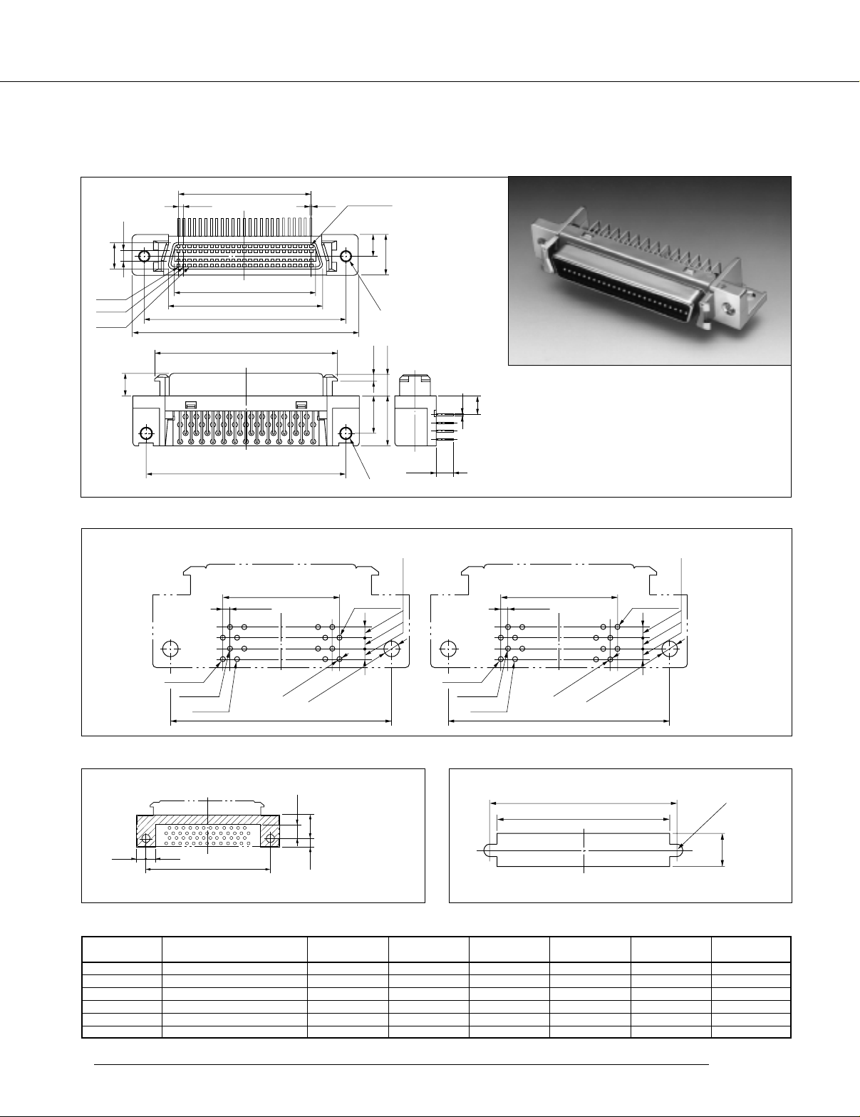
RIGHT-ANGLE SOCKET [METAL SHELL] DIMENSIONS


A


1.27 (0.050)


0.4


End terminal


(0.106)


(0.015)


(0.188)


2.7


4.8


6.3

(0.248)


9.4

(0.379)


No. 1


B


2


C


(0

-


No. 2


.M2


D


.


102)6


No. 3


E


F


(0.338) (0.051)


(0.188)

0.3 (0.011)


1.3

4.8


5.2

(0.204)


8.61

11.5 (0.452)

4.8

(0.188)


2


-


(0


D


.M2


3.9 (0.153)


.


Unit: mm (in.)


102)6


MOUNTING HOLE LAYOUT (COMPONENT SIDE)


26 and 50 contacts


)


20, 36, 68 and 80 contacts


)


±0.1

±0.004


±0.1

±0.004


A ±0.1 (±0.004)


1.905

(0.075


A ±0.1 (±0.004)


1.905

(0.075


1.27 ±0.1 (0.050 ±0.004)


Last No.


1.27 ±0.1 (0.050 ±0.004)


Last No.


.1


1


.


0


0


No. 1


±


No. 1


±


06


8


)


.06


8


)


.


.


.


2


0


2


.004


0


.004


±


φ


No. 2


±


φ


No. 2


0


0


8


) –


±


.8


)


.


.002

2


0


.002

2


0


φ


0


.110


φ


0

.110


No. 3


±


No. 3


±


.031


(0


.031


(0


(0


(0


Unit: mm (in.)


D ±0.1 (±0.004)


D ±0.1 (±0.004)


PATTERN INHIBITED AREAS


RECOMMENDED PANEL DIMENSIONS


–0.004)


R1.5 ±0.1


D ±0.1 ( ±0.004)


(R0.059 ±0.004)


5.3 –0

(0.149


–0

–0.004)


(F + 0.5) ±0.1 ((F + 0.020) ±0.004)


)


8.8

(0.149


±0.1

±0.004


3.4 –0.1


3.2 –0

(0.149 –0.004)


8.1

(0.318

(0.149 –0.004)

3.8 –0.1 (0.149 –0.004)


D ±0.1 (±0.004)


Unit: mm (in.)


Unit: mm (in.)

PART NUMBERS AND DIMENSIONS

Unit: mm (in.)

Number of

Part number

A

B

C

D

E

F

contacts


20

FCN-245D020-G/E

11.43 (0.450)

13.45 (0.529)

16.45 (0.647)

27.45 (1.080)

33.35 (1.312)

23.30 (0.917)

26

FCN-245D026-G/E

15.24 (0.600)

17.26 (0.679)

20.26 (0.797)

31.26 (1.231)

37.16 (1.462)

27.11 (1.067)

36

FCN-245D036-G/E

21.59 (0.850)

23.61 (0.929)

26.61 (1.047)

37.61 (1.480)

43.51 (1.712)

33.46 (1.317)

50

FCN-245D050-G/E

30.48 (1.200)

32.50 (1.279)

35.50 (1.397)

46.50 (1.830)

52.40 (2.062)

42.35 (1.667)

68

FCN-245D068-G/E

41.91 (1.650)

43.93 (1.729)

46.93 (1.847)

57.93 (2.280)

63.83 (2.512)

53.78 (2.117)

80

FCN-245D080-G/E

49.53 (1.950)

51.55 (2.029)

54.55 (2.147)

65.55 (2.580)

71.45 (2.812)

61.40 (2.417)

Specifications

Dimensions are in millimeters (inches)

www.fcai.fujitsu.com


subject to change

2


Loading...
+ 2 hidden pages