

Page 1
查询FCN-215J030供应商查询FCN-215J030供应商
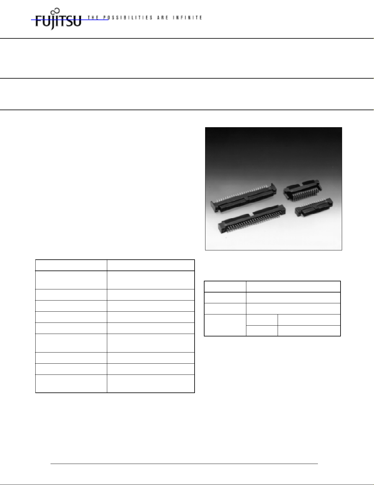
FOR BOARD-TO-BOARD CONNECTION
210 SERIES
■ FEATURES
• 1.27 mm (0.050 in.) pitch contact arrangement in two
rows enables high-density mounting.
• Connectors are available with 30 to 120 contacts.
• Terminals are spaced in a four-row staggered
arrangement (2.54 mm × 1.905 mm.) (0.100 in. ×
0.075 in.) for easy PC board design.
• Sockets are available for board mounting and for
0.635 mm (0.025 in.) pitch flat cable.
[See the description of the FCN-210 series (for boardto-cable connection).]
• Insulation is UL-approved (94V-0).
■ SPECIFICATIONS
Item
Operating temperature
range
Current rating
Voltage rating
Contact resistance
Insulation resistance
Dielectric withstand
voltage
Insertion force
Withdrawal force
Applicable PC board
(standard)
Specifications
–55°C to +105°C
DC 2 A
AC 250 V
35 mΩ max. (DC 6 V, 0.1 V)
1000 MΩ min. (DC 500 V)
500 VAC for 1 minute
4 kg max. (10 pins)
250 g min. (10 pins)
Thickness: 0.8 to 1.6 mm
(0.031 to 0.063 in.)
■ MATERIALS
Item
Insulator
Conductor
Plating
Polyester (UL94V-0)
Copper alloy
Contact
Terminal
Materials
Gold plating
Palladium plating
Specifications
subject to change
Dimensions are in millimeters (inches) www.fcai.fujitsu.com
1
Page 2
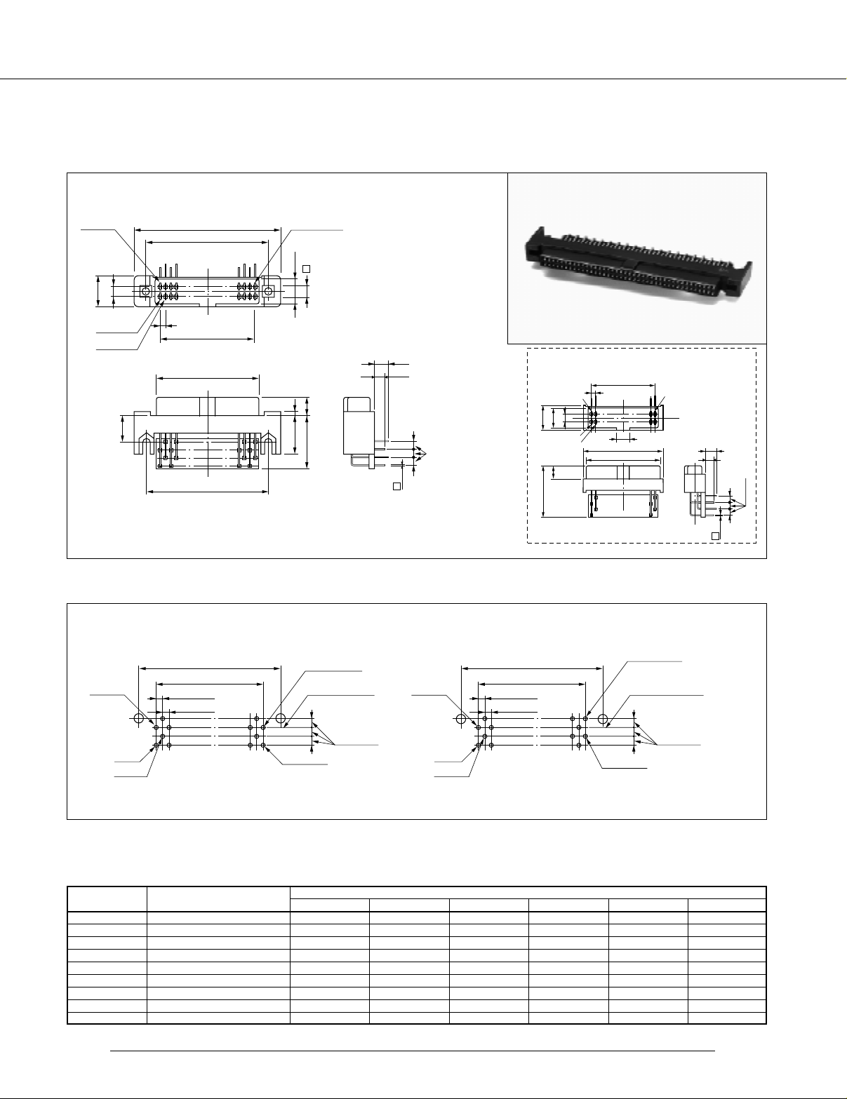
RIGHT-ANGLE SOCKET
■ DIMENSIONS
210 Series
1.27
(0.050)
A
B
C
D
1.5 (0.059)
10 (0.394)
E
No. 2 End terminal
2.54
(0.100)
8
(0.315)
No. 1
No. 3
7.1
(0.280)
■ MOUNTING HOLE LAYOUT
-30, 34 and 50 contacts
Mating side
±0.004)
±0.1 (
E
±0.004)
±0.1 (
No. 2
1.27
1.27
±0.1
±0.1
C
±0.004
(.050
)
±0.004
(.050
)
(0.126)
5.9 (0.232)
3.2
5
(0.197)
13.8
(0.543)
(Component side)
End terminal
+0.2
+0.008
2-φ2.2
-0
(.087
(Mounting hole)
-0
3.5 (0.138)
2.8 (0.110)
0.4
(0.016)
Unit: mm (in.)
No. 2
)
1.905 (0.075)
-40, 60, 80, 92, 100 and 120 contacts
1.27
±0.1
1.27
Mating side
±0.004)
±0.1 (
E
±0.004)
±0.1 (
C
±0.004
(.050
±0.1
(.050
(No-mounting-flange type)
C
1.27
No. 2
5.9 (0.232)
8 (0.315)
2.54 (0.100)
No. 1
No. 3
5 (0.196)
18.8 (0.0740)
)
±0.004
)
(0.050)
4 (0.157)
F
D
End terminal
End terminal
+0.2
2-φ2.2
-0
(.087
(Mounting hole)
+0.008
-0
3.5
(0.138)
)
2.8
(0.110)
0.4
(0.016)
1.905
(0.075)
±0.01
(.075
±0.004
)
No. 1
No. 3
(.031
No. 1
No. 3
φ 0.8
(.031
±0.06
±0.002
1.905
)
The no-mounting-flange type does not require the mounting hole of 2-φ2.2 mm (0.09 in.).
■ PART NUMBERS AND DIMENSIONS
Number of
contacts
30
34
40
50
60
80
92
100
120
Part number
FCN-215J030-G/0
FCN-215J034-G/0
FCN-215J040-G/0
FCN-215J050-G/0
FCN-215J060-G/0
FCN-215J080-G/0
FCN-215J092-G/0
FCN-215J100-G/0
FCN-215J120-G/0
A
31.83 (1.253)
34.73 (1.367)
38.18 (1.503)
44.35 (1.746)
50.88 (2.003)
63.58 (2.503)
71.20 (2.803)
76.28 (3.003)
88.98 (3.503)
26.28 (1.035)
28.82 (1.135)
32.63 (1.285)
38.98 (1.535)
45.33 (1.785)
58.03 (2.285)
65.65 (2.585)
70.73 (2.785)
83.43 (3.285)
Replace “-G/0” with “-G/A” for no-mounting-flange type
Specifications
subject to change
Dimensions are in millimeters (inches) www.fcai.fujitsu.com
B
Dimensions: mm (in.)
C
17.78 (0.700)
20.32 (0.800)
24.13 (0.950)
30.48 (1.200)
36.83 (1.450)
49.53 (1.950)
57.15 (2.250)
62.23 (2.450)
74.93 (2.950)
D
20.68 (0.814)
23.22 (0.914)
27.03 (1.064)
33.38 (1.314)
39.73 (1.564)
52.43 (2.064)
60.05 (2.364)
65.13 (2.564)
77.83 (3.064)
±0.06
φ 0.8
±0.002
)
E
25.28 (0.995)
27.82 (1.095)
31.63 (1.245)
37.98 (1.495)
44.33 (1.745)
57.03 (2.245)
64.65 (2.545)
69.73 (2.745)
82.43 (3.245)
±0.01
(.075
±0.004
1.905
Unit: mm (in.)
F
23.08 (0.908)
34.37 (0.353)
38.18 (1.503)
44.53 (1.753)
50.88 (2.003)
63.58 (2.503)
71.20 (2.803)
76.28 (3.003)
88.98 (3.503)
)
2
Page 3

210 Series
Europe
Fujitsu Components Europe B.V.
Diamantlaan 25
2132 WV Hoofddorp
Netherlands
Tel: (31-23) 5560910
Fax: (31-23) 5560950
Email: info.marketing@fceu.fujitsu.com
Web: www.fceu.fujitsu.com
Asia Pacific
Fujitsu Components Asia Ltd.
102E Pasir Panjang Road
#04-01 Citilink Warehouse Complex
Singapore 118529
Tel: (65) 375-8560
Fax: (65) 273-3021
Email: fcal@fcal.fujitsu.com
www.fcal.fujitsu.com
Fujitsu Components
International
Headquarter
Offices
Japan
Fujitsu Component Limited
Gotanda-Chuo Building
3-5, Higashigotanda 2-chome, Shinagawa-ku
T okyo 141, Japan
Tel: (81-3) 5449-7010
Fax: (81-3) 5449-2626
Email: promothq@ft.ed.fujitsu.com
Web: www.fcl.fujitsu.com
North and South America
Fujitsu Components America, Inc.
250 E. Caribbean Drive
Sunnyvale, CA 94089 U.S.A.
Tel: (1-408) 745-4900
Fax: (1-408) 745-4970
Email: marcom@fcai.fujitsu.com
Web: www.fcai.fujitsu.com
© 2001 Fujitsu Components America, Inc. All company and product names are trademarks or registered trademarks
of their respective owners. Rev. 09/2001
Specifications
subject to change
Dimensions are in millimeters (inches) www.fcai.fujitsu.com
3
 Loading...