

Page 1

FUJITSU Server
PRIMEQUEST
Installation Manual
2000 Series
C122-E174-01EN
Page 2

Preface
This manual describes how to set up this product, including the steps for installation of the PRIMEQUEST 2000 series
server, initialization, and software installation. The manual is intended for system administrators.
For details on the regulatory compliance statements and safety precautions, see the PRIMEQUEST 2000 Series Safety
and Regulatory Information (C122-E171XA).
Errata and addenda for the manual
The PRIMEQUEST2000 Series Errata and Addenda (C122-E182EN) provides errata and addenda for the manual.
Read the PRIMEQUEST2000 Series Errata and Addenda (C122-E182EN) thoroughly in reference to the manual.
Organization of this manual
This manual is organized as follows.
CHAPTER 1 Installation Overview
Chapter 1 describes the workflow up to actual operation of the PRIMEQUEST 2000 series server
CHAPTER 2 Preparing for Main Unit Installation
Chapter 2 describes the preparation before main unit installation. This preparation includes work up t o power
cable connection.
CHAPTER 3 Work before Operating System Installation
Chapter 3 describes the work that must be done before you install an operating system on the PRIMEQUEST 2000 series
server. The chapter also describes settings for actual operation and various setup works.
CHAPTER 4 Installation of Operating System and bundled software
Chapter 4 describes how to install the operating system and bundled software.
Chapter 5 describes how to make various necessary settings after operating system.
CHAPTER 6Work after installation
Chapter 6 describes the work performed after PRIMEQUEST 2000 series installation. This work includes configuring NTP
and security.
CHAPTER 7Power ON and OFF of the partition
Chapter 7 describes partition power control.
Appendix A List of setting items (link)
Appendix A provides links to Appendix A List of Settings in the PRIMEQUEST 2000 Series Tool Reference (C122-
E177EN)
Appendix B About software (link)
Appendix B provides a link to 3.3 Bundled Software in the PRIMEQUEST 2000 Series General Description (C122-
B025EN).
Appendix C Configuring the SAN boot environment (link)
Appendix C is a link to the PRIMEQUEST 1000/2000 Series SAN Boot Environment Configuration Manual (C122E155EN).
Appendix D Notes on VMware installation
Appendix D describes the procedure for installing an internal hard disk in a RAID environment in VMware vSphere and
provides notes on installation
Appendix E Setting up the NTP Server (Windows)
Appendix E describes how to specify and set of an NTP se rver for a specific Windows operating system
Preface
i
Page 3

Preface
Revision History
Edition Date Revised location (type) (*1) Description
1 2014-02-18 - -
*1: Chapter, section, and item numbers in the "Revised location" column refer to those in the latest edition of the
document. However, a number marked with an asterisk (*) denotes a chapter, section, or item in a previous
edition of the document.
ii
Page 4

Preface
Product operating env ironment
This product is a computer intended for use in a computer room environment. For details on the product operating
environment, see the following manual:
PRIMEQUEST 2000 Series Hardware Installation Manual (C122-H007EN)
Safety Prec aut ions
Alert messages
This manual uses the following alert messages to prevent users and bystanders from being injured and to prevent
property damage.
This indicates a hazardous (potentially dangerous) situation that is likely to result in death or serious
personal injury if the user does not perform the procedure correctly.
This indicates a hazardous situation that could result in minor or moderate personal injury if the user
does not perform the procedure correctly. This also indicates that damage to the product or other
property may occur if the user does not perform the procedure correctly.
This indicates information that could help the user use the product more efficiently.
Alert messages in the text
An alert statement follows an alert symbol. An alert statement is indented on both ends to distinguish it from regular text.
Similarly, one space line is inserted before and after the alert statement.
Only Fujitsu certified service engineers should perform the following tasks on this product and the
options provided by Fujitsu. Customers must not perform these tasks under any circumstances.
Otherwise, electric shock, injury, or fire may result.
- Newly installing or moving equipment
- Removing the front, rear, and side covers
- Installing and removing built-in options
- Connecting and disconnecting external interface cables
- Maintenance (repair and periodic diagnosis and maintenance)
The List of important alert items table lists important alert items.
iii
Page 5

Preface
List of important alert items
This manual does not contain important alert items.
This indicates a hazardous (potentially dangerous) situation that is likely to result in death or serious personal injury if the user
does not perform the procedure correctly.
Work
Category
Setup
Field engineers perform the following tasks on this product.
Customers must not perform these tasks under any circumstances.
Otherwise, electric shock, injury, or fire may result.
- Newly installing or moving equipment
- Removing the front, rear, and side covers
- Installing and removing built-in options
- Connecting and disconnecting external interface cables
- - Maintenance (repair and periodic diagnosis and maintenance)
Warning Location
1.1 Setup Workflow
This indicates a hazardous situation that could result in minor or moderate personal injury if the user does not perform the
procedure correctly. This also indicates that damage to the product or other property may occur if the user does not perform
the procedure correctly.
Work
Category
Normal
operation
The unit may be damaged or operating abnormally.
- Follow the precautions, warnings, and instructions shown on the main unit.
- Do not block the vent holes.
- Do not install the main unit in a location exposed to direct sunlight or close to
a device that may generate large amounts of heat.
- Do not install the main unit in a location exposed to large amounts of dust,
corrosive gas, or salt spray.
- Do not install the main unit in a location subject to strong vibration. Install the
main unit on a flat surface.
- Use grounded Category 3 wiring or better. Using another type of grounded
wiring may cause abnormal operation.
- Do not route cables under the main unit. Do not allow cables to become taut.
- Do not disconnect the power cables while the main unit power is on.
- If it is hard to push the connector latch of a LAN cable or other cable when
attempting to disconnect the cable, push it with a flathead screwdriver.
Forcibly inserting a finger may cause personal injury or damage the unit.
- Do not place anything on top of the main unit. Do not work above or on top of
Warning Location
2.1Safety
Precautions
iv
Page 6

Preface
representative or field engineer without turning on the power supply again.
Normal
operation
the main unit.
- Prevent rapid rises in the ambient temperature during winter. Such an abrupt
temperature change may cause condensation to form in the main unit. Allow
sufficient warm-up time before starting operation.
- Do not install the main unit close to a photocopier, air-conditioning unit,
welder, or other device that generates electromagnetic noise.
- Do not install the main unit close to a device that generates large amounts of
electrical noise.
- Do not connect the main unit to the same power supply line as an elevator in
the facility or other equipment that would expose it to sudden voltage drops.
- Implement antistatic measures at the installation site.
- Confirm that the power supply voltage and frequency are adequate
according to the respective ratings shown on the main unit.
- Do not insert or drop foreign matter into the openings of the main unit. The
main unit contains high-voltage components. If any metallic matter or other
electro-conductive object enters the main unit through an opening, it may
cause a short circuit. This may lead to fire, electric shock, or damage to the
main unit.
- For details on maintenance of the main unit, contact the distributor where you
purchased your product, or your sales representative.
(Ignition)
When over current is detected and the power is cut off by tripping the breaker of the
AC power or op tional po wer dis tributio n bo x, the re is a possib ilit y th at fa ilu re, s uch
as short circuit occurring in the main unit. In such case, contact to your sales
3.2.1 Power-on/off
of main unit
Normal
operation
Normal
operation
(Damage to data)
Confirm that the System Power LED of the OPL is off before turning off the main
power. If you turn off the main power while the System Power LED of the OPL is
on, data may be damaged.
(Damage to data)
Confirm that selection of disk is right, when choosing a dumping device. If selection
is mistaken, data may be damaged.
3.2.1 Power-on/off
of main unit
5.3 Setting of
sadump
v
Page 7
Preface
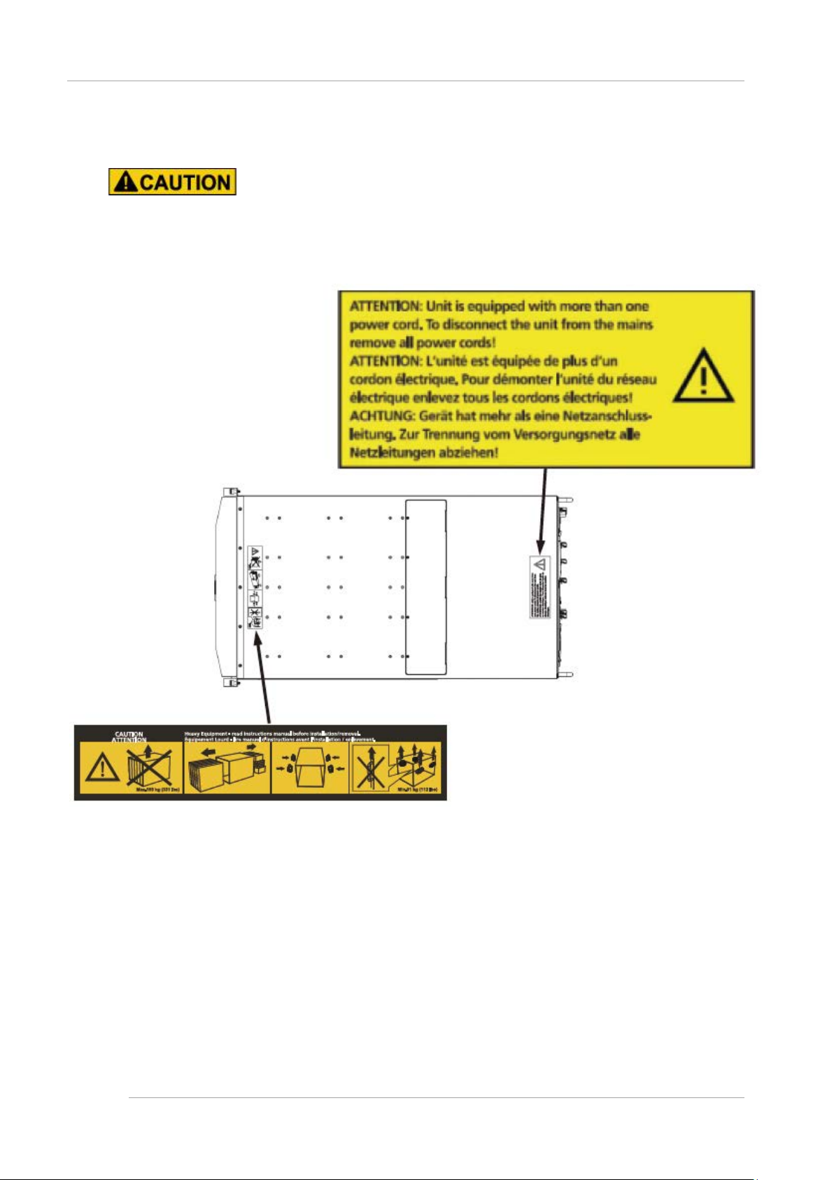
Warning labels
Never remove the warning labels.
Warning label location (the main cabinet top )
vi
Page 8
Preface
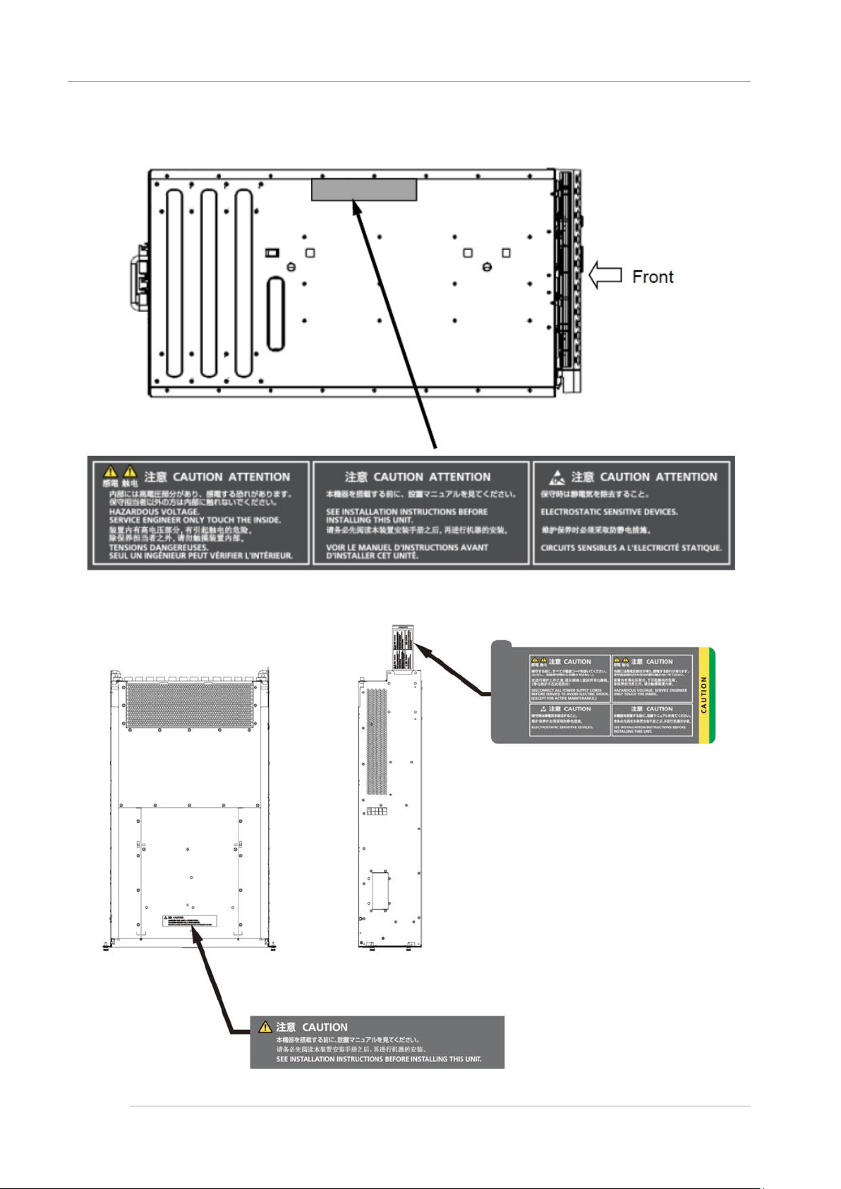
Warning label location (the main cabinet l eft)
Warning label location (PCI_Box)
vii
Page 9

Preface
Notes on Handling the Product
About this product
This product is designed and manufactured for standard applications. Such applications include, but are not limited to,
general office work, personal and home use, and general industrial use. The product is not intended for applications that
require extremely high levels of safety to be guaranteed (referred to below as "safety-critical" applications). Use of the
product for a safety-critical application may present a significant risk of personal injury and/or death. Such applications
include, but are not limited to, nuclear reactor control, aircraft flight control, air traffic control, mass transit control, medical
life support, and missile launch control. Customers shall not use the product for a safety-critical application without
guaranteeing the required level of safety. Customers who plan to use the product in a safety-critical system are requested
to consult the Fujitsu sales representatives in charge.
Storage of accessories
Keep the accessories in a safe place because they are required for server operation.
Adding optional products
For stable operation of the PRIMEQUEST 2000 series server, use only a Fujitsu-certified optional product as an added
option.
Note that the PRIMEQUEST 2000 series server is not guaranteed to operate with any optional product not certified by
Fujitsu.
Maintenance
Only Fujitsu certified service engineers should perform the following tasks on this product and the
options provided by Fujitsu. Customers must not perform these tasks under any circumstances.
Otherwise, electric shock, injury, or fire may result.
- Newly installing or moving equipment
- Removing the front, rear, and side covers
- Installing and removing built-in options
- Connecting and disconnecting external interface cables
- Maintenance (repair and periodic diagnosis and maintenance)
Only Fujitsu certified service engineers should perform the following tasks on this product and the
options provided by Fujitsu. Customers must not perform these tasks under any circumstances.
Otherwise, product failure may result. PRIMEQUEST 2000 Series General Description
- Unpacking an optional Fujitsu product, such as an optional adapter, delivered to the customer
Modifying or recycling the product
Modifying this product or recycling a secondhand product by overhauling it without prior approval
may result in personal injury to users and/or bystanders or damage to the product and/or other
property.
viii
Page 10

Preface
Note on erasing data from hard disks when disposing of the product or transferring it
Disposing of this product or transferring it as is may enable third parties to access the data on the hard disk and use it for
unforeseen purposes. To prevent the leakage of confidential information and important data, all of the data on the hard
disk must be erased before disposal or transfer of the product.
However, it can be difficult to completely erase all of the data from the hard disk. Simply initializing (reformatting) the hard
disk or deleting files on the operating system is insufficient to erase the data, even though the data appears at a glance to
have been erased. This type of operation only makes it impossible to access the data from the operating system.
Malicious third parties can restore this data.
If you save your confidential information or other important data on the hard disk, you should completely erase the data,
instead of simply carrying out the aforementioned operation, to prevent the data from being restored. To prevent important
data on the hard disk from being leaked when the product is disposed of or transferred, you will need to take care to erase
all the data recorded on the hard disk on your own responsibility.
Furthermore, if a software license agreement restricts the transfer of the software (operating system and application
software) on the hard disk in the server or other product to a third party, transferring the product without deleting the
software from the hard disk may violate the agreement. Adequate verification from this point of view is also necessary.
Product and service inquiries
For all product use and technical inquiries, contact the distributor where you purchased your product, or a Fujitsu sales
representative or systems engineer (SE). If you do not know the appropriate contact address for inquiries about the
PRIMEQUEST 2000 series, use the Fujitsu contact line.
Fujitsu contact line
We accept Web inquiries. For details, visit our website:
https://www-s.fujitsu.com/global/contact/computing/PRMQST_feedback.html
Warranty
If a component failure occurs during the warranty period, we will repair it free of charge in accordance with the terms of the
warranty agreement. For details, see the warranty.
Before requesting a repair
If a problem occurs with the product, confirm the problem by referring to 11.2 Troubleshooting in the PRIMEQUEST 2000
Series Administration Manual (C122-E175EN). If the error recurs, contact your sales representative or a field engineer.
Confirm the model name and serial number shown on the label affixed to the right front of the device and report it. Also
check any other required items beforehand according to 11.2 Troubleshooting in the PRIMEQUEST 2000 Series
Administration Manual (C122-E175EN).
The system settings saved by the customer will be used during maintenance.
ix
Page 11

Preface
Manual
How to use this manual
This manual contains important information about the safe use of this product. Read the manual thoroughly to understand
the information in it before using this product. Be sure to keep this manual in a safe and convenient location for quick
reference.
Fujitsu makes every effort to prevent users and bystanders from being injured and to prevent property damage. Be sure to
use the product according to the instructions in this manual.
Manuals for the PRIMEQUEST 2000 series
The following manuals have been prepared to provide you with the information necessary to use the PRIMEQUEST 2000
series.
You can access HTML versions of these manuals at the following sites:
Japanese-language site: http://jp.fujitsu.com/platform/server/primequest/manual/2000/
Global site: http://www.fujitsu.com/global/services/computing/server/primequest/
http://manuals.ts.fujitsu.com/
Title
PRIMEQUEST 2000 Series Getting
Started Guide
PRIMEQUEST 2000 Series Safety
and Regulatory Information
PRIMEQUEST 2000 Series Errata
and Addenda
PRIMEQUEST 2000 Series
General Description
SPARC Enterprise / PRIMEQUES T
Common Installation Planning
Manual
PRIMEQUEST 2000 Series
Hardware Installation Manual
PRIMEQUEST 2000 Series
Installation Manual
PRIMEQUEST 2000 Series User
Interface Operating Instructions
PRIMEQUEST 2000 Series
Administration Manual
PRIMEQUEST 2000 Series Tool
Reference
PRIMEQUEST 2000 Series
Message Reference
Describes what manuals you should read and how to access
important information after unpacking the PRIMEQUEST 2000
series server. (This manual comes with the product.)
Contains important information required for using the
PRIMEQUEST 2000 series safely.
Provides errata and addenda for the PRIMEQUEST 2000 series
manuals. This manual will be updated as needed.
Describes the functions and features of the PRIMEQUEST 2000
series.
Provides the necessary information and concepts you should
understand for installation and facility planning for SPARC
Enterprise and PRIMEQUEST installations.
Includes the specifications of and the installation location
requirements for the PRIMEQUEST 2000 series.
Describes how to set up the PRIMEQUEST 2000 series server,
including the steps for installation preparation, initialization, and
software installation.
Describes how to use the Web-UI and UEFI to assure proper
operation of the PRIMEQUEST 2000 series server.
Describes how to use tools and software for system
administration and how to maintain the system (component
replacement and error notification).
Provides information on operation methods and settings, including
details on the MMB and UEFI functions.
Lists the messages that may be displayed when a problem occurs
during operation and describes how to respond to them.
Description
Manual code
C122-E170XA
C122-E171XA
C122-E182EN
C122-B025EN
C120-H007EN
C122-H007EN
C122-E174EN
C122-E176EN
C122-E175EN
C122-E177EN
C122-E178EN
x
Page 12

Preface
Title
PRIMEQUEST 2000 Series
REMCS Installation Manual
PRIMEQUEST 2000 Series
Glossary
Describes REMCS service installation and operation C122-E180EN
Defines the PRIMEQUEST 2000 series related terms and
abbreviations.
Description
Related m anuals
The following manuals relate to the PRIMEQUEST 2000 series.
You can access these manuals at the following site:
http://www.fujitsu.com/global/services/computing/server/primequest/
http://manuals.ts.fujitsu.com/
Contact your sales representative for inquiries about the ServerView manuals
Title
ServerView Suite ServerView
Operations Manager Quick
Installation (Windows)
ServerView Suite ServerView
Operations Manager Quick
Installation (Linux)
ServerView Suite ServerView
Installation Manager
ServerView Suite ServerView
Operations Manager Server
Management
ServerView Suite ServerView
RAID Management User
Manual
ServerView Suite Basic
Concepts
ServerView Operations
Manager Installation
ServerView Agents for Linux
ServerView Operations
Manager Installation
ServerView Agents for
Windows
ServerView Mission Critical
Option User Manual
ServerView RAID Manager
VMware vSphere ESXi 5
Installation Guide
Describes how to install and start ServerView Operations
Manager in a Windows environment.
Describes how to install and start ServerView Operations
Manager in a Linux environment.
Describes the installation procedure using ServerView Installation
Manager.
Provides an overview of server monitoring using ServerView
Operations Manager, and describes the user interface of
ServerView Operations Manager.
Describes RAID management using ServerView RAID Manager. None
Describes basic concepts about ServerView Suite. None
Describes installation and update installation of ServerView Linux
Agent.
Describes installation and update installation of ServerView
Windows Agent.
Describes the necessary functions unique to PRIMEQUEST
(notification via the MMB, hot replacement command) and
ServerView Mission Critical Option (SVmco), which is required for
supporting these functions.
Describes the installation and settings required to use ServerView
RAID Manager on the VMware vSphere ESXi 5 server.
Description
Manual code
C122-E179EN
Manual code
None
None
None
None
None
None
None
None
xi
Page 13

Preface
Title
MegaRAID SAS Softw are Provides technical information on using RAID controllers.
Refer to the manual from the SVS-ServerView Suite ServerBooks
DVD(Manual)2 supplied with the product or from the following
URL:
The Fujitsu Technology Solutions manuals server
http://manuals.ts.fujitsu.com/
MegaRAID SA S Devi ce
Driver Installation
Modular RA ID C ont rol ler
Installation Guide
Provides technical information on using RAID controllers.
Refer to the manual from the SVS-ServerView Suite ServerBooks
DVD(Manual)2 supplied with the product or from the following
URL:
The Fujitsu Technology Solutions manuals server
http://manuals.ts.fujitsu.com/
Provides technical information on using RAID controllers.
Refer to the manual from the SVS-ServerView Suite ServerBooks
DVD(Manual)2 supplied with the product or from the following
URL:
The Fujitsu Technology Solutions manuals server
http://manuals.ts.fujitsu.com/
Description
Manual code
None
None
None
Abbreviations
This manual uses the following product name abbreviations.
Formal product name Abbreviation
Microsoft ® Windows Server ® 2012 R2 Standard Windows, Windows Server 2012
Microsof t ® Wind ows Serv er ® 20 12 R2 Datacenter
Microsoft ® Windows Server ® 2012 St andar d
Microsoft ® Windows Server ® 2012 Datacenter
Microsoft ® Windows Server ® 2008 R2 Standard Windows, Windows Server 2008
Microsoft ® Windows Server ® 2008 R2 Enterprise
Microsoft ® Windows Server ® 2008 R2 Datacenter
Red Hat ® Enterprise Linux ® 6 (for Intel64) Linux, RHEL6, RHEL
Novell (R) SUSE(R) LINUX Enterprise Server 11 Service Pack 3 SLES11 SP3
Oracle Linux 6 (x86_64) Oracle Linux, Oracle Linux 6
VMware vSphere (R) 5 VMware, vS phere 5 .x, VM ware 5, VMware 5 .x
VMware (R) ESXi (TM) 5 ESXi, ESXi 5, ESXi 5.x
Trademarks
- Microsoft, Windows, and Windows Server are trademarks or registered trademarks of Microsoft Corporation in the
United States and/or other countries.
- Linux is a registered trademark of Linus Torvalds.
- Red Hat, the Shadowman logo and JBoss are registered trademarks of Red Hat, Inc. in the U.S. and other countries.
- Intel, Intel logo, Intel Inside, Intel Inside logo, Intel Atom, Intel Atom Inside, Intel Core, Core Inside, Intel vPro, vPro
Inside, Celeron, Celeron Inside, Itanium, Itanium Inside, Pentium, Pentium Inside, Xeon, Xeon Phi, Xeon Inside,
xii
Page 14

Preface
Ultrabook are trademarks or registered trademarks of Intel Corporation.
- Ethernet is a registered trademark of Fuji Xerox Co., Ltd. in Japan and is a registered trademark of Xerox Corp. in
the United States and other countries.
- VMware is a trademark or registered trademark of VMware, Inc. in the United States and other countries.
- Novell and SUSE Linux Enterprise Server are trademarks of Novell, Inc.
- Xen is a trademark or registered trademark of Citrix Systems, Inc. or its subsidiaries in the United States and other
countries.
- Other company names and product names are the trademarks or registered trademarks of their respective owners.
- Trademark indications are omitted for some system and product names in this manual.
Notation
This manual uses the following fonts and symbols to express specific types of information.
Font or symbols Meaning Example
Italics Title of a manual that you should refer to See the PRIMEQUEST 2000 Series
Installation Manual (C122-E174EN).
[ ]
Window names as well as the names of
buttons, tabs, and drop-down menus in
windows are enclosed in brackets.
Click the [OK] button.
Notation for the CLI (command line interface)
The following notation is used for commands.
Command syntax
Command syntax is represented as follows.
- Variables requiring the entry of a value are enclosed in angle brackets < >
- Optional elements are enclosed in brackets [ ].
- Options for optional keywords are grouped in | (stroke) separated lists enclosed in brackets [ ].
- Options for required keywords are grouped in | (stroke) separated lists enclosed in braces { }.
Command syntax is written in a box.
Remarks
The command output shown in the PDF manuals may include line feeds at places where there is no line feed symbol (¥ at
the end of the line).
Notes on notations
- If you have a comment or request regarding this manual, or if you find any part of this manual unclear, please take a
moment to share it with us by filling in the form at the following webpage, stating your points specifically, and sending
the form to us:
https://www-s.fujitsu.com/global/contact/computing/PRMQST_feedback.html
- The contents of this manual may be revised without prior notice.
- In this manual, the Management Board and MMB firmware are abbreviated as "MMB."
- In this manual, IOU_10GbE and IOU_1GbE are collectively referred to as IO Units.
- Screenshots contained in this manual may differ from the actual product screen displays.
- The IP addresses, configuration information, and other such information contained in this manual are display
xiii
Page 15

Preface
examples and differ from that for actual operation.
- The PDF file of this manual is intended for display using Adobe® Reader® in single page viewing mode at 100%
zoom.
This manual shall not be reproduced or copied without the permission of Fujitsu Limited.
Copyright 2014 FU JITSU LIMIT ED
xiv
Page 16

Preface
Contents
Preface ................................................................................................................................................................................................................ i
Installation Overview ............................................................................................................................................................ 1 CHAPTER 1
Setup Workflow .............................................................................................................................................................................. 1
1.1
1.1.1 Work performed by a field engineer ......................................................................................................................................... 1
1.1.2 Work perf ormed by the us er ..................................................................................................................................................... 2
Preparing for Main Unit Installation ..................................................................................................................................... 3 CHAPT ER 2
Safety Precautions ......................................................................................................................................................................... 3
2.1
2.2 Before Installing the Main Unit ...................................................................................................................................................... 4
2.3 Checking Environmental Conditions ............................................................................................................................................ 4
2.4 Preparing the Power Supply Equipment ...................................................................................................................................... 4
2.4.1 Electrical specifications ............................................................................................................................................................. 4
2.4.2 Facility power requirements and characteristics ..................................................................................................................... 4
2.4.3 Grounding.................................................................................................................................................................................. 5
2.5 Checking the Installation Site ........................................................................................................................................................ 5
2.6 Preparing to Install the Main Unit .................................................................................................................................................. 5
2.7 Confirming the Supplied Parts ...................................................................................................................................................... 5
2.8 Mounting the Main Unit in a 19-inch Rack .................................................................................................................................... 6
2.9 Connecting the Power Cables ...................................................................................................................................................... 6
Work before Operating System Installation ........................................................................................................................ 8 CHAPTER 3
Before Starting Setup .................................................................................................................................................................... 8
3.1
3.1.1 MMB Settings ............................................................................................................................................................................ 8
3.1.2 Partition Settings ....................................................................................................................................................................... 8
3.2 System Startup .............................................................................................................................................................................. 8
3.2.1 Power-on/off of main unit .......................................................................................................................................................... 9
3.3 Connection and Setting of MMB ................................................................................................................................................... 9
3.3.1 Connecting the MMB console PC ......................................................................................................................................... 11
3.3.2 MMB Initialization. ................................................................................................................................................................... 12
3.3.3 Setting of Connection for Actual operating Environment ...................................................................................................... 13
3.3.4 Login to MMB .......................................................................................................................................................................... 15
3.3.5 Web-UI Window View ............................................................................................................................................................ 16
3.3.6 Network set up of MMB .......................................................................................................................................................... 17
3.3.7 Set up of telnet ........................................................................................................................................................................ 19
3.3.8 Configuration of DNS server .................................................................................................................................................. 21
3.3.9 Set up of Alarm E-Mail ............................................................................................................................................................ 23
3.3.10 Registration of User Account ............................................................................................................................................. 25
3.3.11 Setting of System Name .................................................................................................................................................... 28
3.3.12 Setting of Date and Time ................................................................................................................................................... 29
3.4 Partition Configuration ................................................................................................................................................................. 31
3.4.1 Setting the partition configuration ........................................................................................................................................... 31
3.4.2 Setting the Home SB .............................................................................................................................................................. 34
3.4.3 Setting of Reserved SB .......................................................................................................................................................... 36
3.4.4 Partition name settings ........................................................................................................................................................... 39
xv
Page 17

Preface
3.4.5 Various mode settings ............................................................................................................................................................ 40
3.4.6 Settings of Console Redirection ............................................................................................................................................. 42
3.4.7 Power OFF and ON of the partition ....................................................................................................................................... 44
3.4.8 Confirmation of partition information ...................................................................................................................................... 44
3.5 Storage of the configuration information ..................................................................................................................................... 45
3.5.1 Backup of the MMB configuration information ...................................................................................................................... 45
Installation of Operating System and bundled software................................................................................................... 47 CHAPTER 4
Installation procedure of Operating System and bundled software .......................................................................................... 47
4.1
4.2 Procedure to install Windows in SAN/iSCSI storage device ..................................................................................................... 47
4.2.1 Presetting ................................................................................................................................................................................ 47
4.2.2 Preparation for installation ...................................................................................................................................................... 48
4.2.3 Installation of operating system .............................................................................................................................................. 48
4.2.4 Bundled software setting after installation is completed ....................................................................................................... 49
4.2.5 Connection of SAN and the internal HDD/SDD after installation ......................................................................................... 50
4.3 Procedures to install Windows into internal HDD/SSD ............................................................................................................. 51
4.3.1 Presetting ................................................................................................................................................................................ 51
4.3.2 Preparations for installation .................................................................................................................................................... 51
4.3.3 Installation of operating system .............................................................................................................................................. 51
4.3.4 Setting the bundled software after completion of installation ................................................................................................ 52
4.3.5 After Installation, Connection between SAN and internal HDD/SSD................................................................................... 54
4.4 Procedures to install RHEL in SAN storage device ................................................................................................................... 54
4.4.1 Presetting ................................................................................................................................................................................ 54
4.4.2 Preparation for installation ...................................................................................................................................................... 55
4.4.3 Execution of installation .......................................................................................................................................................... 55
4.4.4 Configuring Bundled Software after Installation .................................................................................................................... 56
4.4.5 After installation, connecting SAN and internal HDD/SSD .................................................................................................. 57
4.5 Procedure to install RHEL into internal HDD/SSD ..................................................................................................................... 57
4.5.1 Presetting ................................................................................................................................................................................ 57
4.5.2 Preparing for Installation ......................................................................................................................................................... 58
4.5.3 Installation ................................................................................................................................................................................ 58
4.5.4 Configuring Bundled Software after Installation .................................................................................................................... 59
4.5.5 After installation, connecting SAN with internal HDD/SSD ................................................................................................... 60
4.6 Procedure to install VMware 5.x on the SAN storage device ................................................................................................... 60
4.6.1 Presetting ................................................................................................................................................................................ 61
4.6.2 Preparation of installation ....................................................................................................................................................... 61
4.6.3 Installation of VMware 5.x....................................................................................................................................................... 61
4.6.4 Setting of Software Watchdog................................................................................................................................................ 62
4.6.5 VMware 5.x Installation completion. ...................................................................................................................................... 62
4.6.6 Installation of Bundled Software ............................................................................................................................................. 63
4.7 Procedure to install VMware 5.x into internal HDD/SSD ........................................................................................................... 63
4.7.1 Presetting ................................................................................................................................................................................ 63
4.7.2 Preparation of installation ....................................................................................................................................................... 63
4.7.3 VMware 5.x installation ........................................................................................................................................................... 64
4.7.4 Setting of software watchdog ................................................................................................................................................. 64
4.7.5 Completion of VMware 5.x installation ................................................................................................................................... 65
xvi
Page 18

Preface
4.7.6 Installation of the bundled software ........................................................................................................................................ 65
4.8 Procedure of Hyper-V installation ............................................................................................................................................... 65
4.9 Procedure of KVM installation ..................................................................................................................................................... 65
4.10 Procedure to install SUSE Linux Enterprise Server 11 Service Pack 3 into the SAN Storage Unit ....................................... 66
4.10.1 Presetting ............................................................................................................................................................................ 66
4.10.2 Preparation of installation ................................................................................................................................................... 66
4.10.3 Installation ........................................................................................................................................................................... 66
4.10.4 Configuring Bundled Software after Installation................................................................................................................ 68
4.10.5 After installation, connecting SAN and internal HDD/SSD ............................................................................................. 68
4.11 Procedure to install SUSE Linux Enterprise Server 11 Service Pack 3 into the Internal HDD ............................................... 70
4.11.1 Presetting ............................................................................................................................................................................ 70
4.11.2 Preparing for Installation .................................................................................................................................................... 70
4.11.3 Installation ........................................................................................................................................................................... 70
4.11.4 Configuring Bundled Software after Installation................................................................................................................ 71
4.11.5 After installation, connecting SAN and internal HDD/SSD .............................................................................................. 71
Work after Operating System installation.......................................................................................................................... 72 CHAPTER 5
Types of work ............................................................................................................................................................................... 72
5.1
5.2 Setting of SVS (SVagent/SVmco) .............................................................................................................................................. 72
5.3 Setting of sadump ........................................................................................................................................................................ 72
5.4 Setup of dump environment (Windows) ..................................................................................................................................... 88
5.4.1 About memory dump file/paging file ...................................................................................................................................... 88
5.5 Setup of dump environment (Linux) ........................................................................................................................................... 88
5.5.1 How to use sadump (Linux) ................................................................................................................................................... 89
5.6 Setup of NTP client ...................................................................................................................................................................... 91
5.7 Saving management and configuration information .................................................................................................................. 91
5.7.1 Storage of MMB configuration information ............................................................................................................................ 91
5.7.2 Storage of BIOS configuration information ............................................................................................................................ 92
5.8 Setup for lifespan monitoring according to RAS support service .............................................................................................. 93
5.8.1 Monitoring life-span of UPS battery ....................................................................................................................................... 93
5.9 “Write Policy” recommended setting of SAS array controller card ............................................................................................ 93
Work after installation ......................................................................................................................................................... 94 CHAPTER 6
Redundant configuration of network adaptor ............................................................................................................................. 94
6.1
6.2 NTP Configuration ....................................................................................................................................................................... 95
6.2.1 Method of operating NTP in PRIMEQUEST 2000 series .................................................................................................... 95
6.2.2 Setting NTP server ................................................................................................................................................................. 96
6.3 Configuring DNS server .............................................................................................................................................................. 97
6.4 Set up of SMTP ........................................................................................................................................................................... 98
6.5 Set up of security ......................................................................................................................................................................... 98
6.5.1 Set up of Access Control ........................................................................................................................................................ 99
6.5.2 Set up of SNMP ................................................................................................................................................................... 101
6.5.3 Set up of SSH ...................................................................................................................................................................... 105
6.5.4 HTTPS Settings ................................................................................................................................................................... 106
6.6 Schedule operations ................................................................................................................................................................. 107
Power ON and OFF of the partition ............................................................................................................................... 108 CHAPTER 7
Related to the power ON and OFF of the partition ................................................................................................................. 108
7.1
xvii
Page 19

Preface
7.1.1 Power ON of the partition .................................................................................................................................................... 108
7.1.2 Power OFF of the partition .................................................................................................................................................. 109
Appendix A List of setting items (link) .......................................................................................................................................................... 111
A.1 Setting items of MMB ........................................................................................................................................................................ 111
A.2 Setting items of UEFI ......................................................................................................................................................................... 111
A.3 Setting items of BMC ......................................................................................................................................................................... 111
Appendix B About software (link) ................................................................................................................................................................ 112
B.1 Types and general description of the bundled software .................................................................................................................. 112
Appendix C Configuring the SAN boot environment (link) ......................................................................................................................... 113
Appendix D Notes on VMware installation ................................................................................................................................................. 114
D.1 Building the RAID environment in the VMware 5.x internal disk..................................................................................................... 114
D.2 Installing VMware 5.x Bundled Software ......................................................................................................................................... 114
Appendix E Setting up the NTP Server (Windows) ................................................................................................................................... 115
E.1 Overview of NTP Client Settings ...................................................................................................................................................... 115
E.2 NTP Settings in Windows Server 2012 and Windows Server 2012 R2 ........................................................................................ 116
E.2.1 Specifying an NTP Server.......................................................................................................................................................... 116
E.2.2 Synchronization Interval and Startup Settings of NTP Service ................................................................................................ 120
E.2.3 Event Task Settings ................................................................................................................................................................... 122
E.3 NTP Settings in Windows Server 2008 R2 ...................................................................................................................................... 129
E.3.1 Specifying an NTP Server.......................................................................................................................................................... 129
E.3.2 Synchronization Interval and Startup Settings of NTP Service .................................................................................................... 131
E.3.3 Event Task Settings ....................................................................................................................................................................... 133
xviii
Page 20

Preface
Figures
FIGURE 2.1 Power cable socket locations (PRIMEQUEST2000 Series) ............................................................................................ 7
FIGURE 2.2 Power cable socket locations (PCI_Box) ........................................................................................................................... 7
FIGURE 3.1 External Views of Mounting Locations and External interface of MMB .......................................................................... 11
FIGURE 3.2 Location of MMB user port ................................................................................................................................................ 13
FIGURE 3.3 Network Configuration and IP Address of Management LAN ........................................................................................ 14
FIGURE 3.4 MMB Web-UI [Login] Window .......................................................................................................................................... 16
FIGURE 3.5 Example of [IPv4 Interface] Window ................................................................................................................................ 18
FIGURE 3.6 Example of [IPv6 Interface] Window ................................................................................................................................ 18
FIGURE 3.7 Example of [Network Protocols] Window ......................................................................................................................... 20
FIGURE 3.8 Example of [IPv4 Interface] Window ................................................................................................................................ 21
FIGURE 3.9 Example of [IPv6 Interface] Window ................................................................................................................................ 22
FIGURE 3.10 Example of [Alarm E-Mail] Window ................................................................................................................................ 23
FIGURE 3.11 Example of [Alarm E-Mail Filtering Condition] Window ................................................................................................. 24
FIGURE 3.12 Example of [User List] Window ....................................................................................................................................... 25
FIGURE 3.13 Example of [Add User] Window ..................................................................................................................................... 26
FIGURE 3.14 Example of [Edit User] Window ...................................................................................................................................... 27
FIGURE 3.15 [System Information] Window Example ......................................................................................................................... 28
FIGURE 3.16 [Date/ Time] Window Example ....................................................................................................................................... 29
FIGURE 3.17 [Management LAN Port Configuration] Windows Example ......................................................................................... 30
FIGURE 3.18 [Partition Configuration] Window Example..................................................................................................................... 31
FIGURE 3.19 Example of [Add SB/IOU to Partition] Window .............................................................................................................. 32
FIGURE 3.20 [Partition Configuration] Window Example..................................................................................................................... 33
FIGURE 3.21 Example of [Remove SB/IOU from Partition] Window .................................................................................................. 34
FIGURE 3.22 Example of [Partition Home] Window ............................................................................................................................ 35
FIGURE 3.23 Example of [Reserved SB Configuration] Window ........................................................................................................ 36
FIGURE 3.24 Settings of BlueScreenTimeout ([Configuration] tab) .................................................................................................... 38
FIGURE 3.25 Settings of BlueScreenTimeout (Settings of [Misc]) ...................................................................................................... 39
FIGURE 3.26 Example of [Partition Configuration] Window ................................................................................................................ 40
FIGURE 3.27 Example of [IPv4 Console Redirection Setup] Window ................................................................................................ 43
FIGURE 3.28 Example of [IPv6 Console Redirection Setup] Window ................................................................................................ 44
FIGURE 3.29 Example of [Information] Window ................................................................................................................................... 45
FIGURE 3.30 Example of [Backup/Restore MMB Configuration] Window ......................................................................................... 46
FIGURE 4.1 File Structure ...................................................................................................................................................................... 57
FIGURE 4.2 File Structure ...................................................................................................................................................................... 60
FIGURE 5.1 Example of Device Manager Menu .................................................................................................................................. 73
FIGURE 5.2 Main menu (sadump) ........................................................................................................................................................ 74
FIGURE 5.3 sadump set-up menu ........................................................................................................................................................ 75
FIGURE 5.4 sadump set-up menu ........................................................................................................................................................ 76
FIGURE 5.5 Main menu (sadump) ........................................................................................................................................................ 77
FIGURE 5.6 Dump Device Maintenance Menu .................................................................................................................................... 78
FIGURE 5.7 Dump Device Structure Menu .......................................................................................................................................... 79
FIGURE 5.8 Dump Device Selection Menu .......................................................................................................................................... 80
xix
Page 21

Preface
FIGURE 5.9 Dump Device Selection Menu .......................................................................................................................................... 81
FIGURE 5.10 Dump Device Structure Menu ........................................................................................................................................ 82
FIGURE 5.11 Dump Device Maintenance Menu.................................................................................................................................. 83
FIGURE 5.12 Dump Device Setting Menu ............................................................................................................................................ 84
FIGURE 5.13 Dump Device List Menu.................................................................................................................................................. 85
FIGURE 5.14 Dump Device Setting Menu ............................................................................................................................................ 86
FIGURE 5.15 Dump Device Maintenance Menu.................................................................................................................................. 87
FIGURE 5.16 Main Menu (sadump) ...................................................................................................................................................... 88
FIGURE 5.17 Example of [Backup/Restore MMB Configuration] Window ......................................................................................... 91
FIGURE 5.18 Example of [Backup BIOS Configuration] ...................................................................................................................... 92
FIGURE 6.1 External network configuration .......................................................................................................................................... 94
FIGURE 6.2 Operation Diagram when External NTP Server is used (When thre e NTP serv ers ar e used ) ..................................... 96
FIGURE 6.3 Example of [Date/Time] Window ...................................................................................................................................... 97
FIGURE 6.4 Example of [Access Control] Window .............................................................................................................................. 98
FIGURE 6.5 Example of [Add Filter] Window ....................................................................................................................................... 99
FIGURE 6.6 Example of [Access Control] Window ........................................................................................................................... 100
FIGURE 6.7 Example of [Add Filter] Window .................................................................................................................................... 101
FIGURE 6.8 Example of [Network Protocols] Window ...................................................................................................................... 102
FIGURE 6.9 Example of [SNMP Community] Window ..................................................................................................................... 103
FIGURE 6.10 Example of [SNMP Trap] Window .............................................................................................................................. 104
FIGURE 6.11 Example of [SNMP v3 Configuration] ......................................................................................................................... 105
FIGURE 6.12 Example of [Network Protocols] Window .................................................................................................................... 106
FIGURE 6.13 Example of [Network Protocols] window ..................................................................................................................... 107
FIGURE 7.1 Example of [Power Control] window ............................................................................................................................. 108
FIGURE 7.2 Example of [Power Control] window ............................................................................................................................. 109
FIGURE E.1 Settings for system clock synchronization .................................................................................................................... 115
FIGURE E.2 [Date and Time] window (1) .......................................................................................................................................... 117
FIGURE E.3 [Date and Time] window (2) .......................................................................................................................................... 118
FIGURE E.4 [Internet Time Settings] window .................................................................................................................................... 119
FIGURE E.5 [Registry Editor] selection window ................................................................................................................................. 120
FIGURE E.6 [Registry Editor] window ................................................................................................................................................ 121
FIGURE E.7 [Windows Time Properties] window .............................................................................................................................. 122
FIGURE E.8 [Task Scheduler] window .............................................................................................................................................. 123
FIGURE E.9 [Create Basic Task Wizard] window (Create a Basic Task) ........................................................................................ 123
FIGURE E.10 [Create Basic Task Wizard] window (Task Trigger) ................................................................................................... 124
FIGURE E.11 [Create Basic Task Wizard] window (When a Specific Event Is Logged) ................................................................ 125
FIGURE E.12 [Create Basic Task Wizard] window (Action) ............................................................................................................. 125
FIGURE E.13 [Create Basic Task Wizard] window (Start a Program) ............................................................................................. 126
FIGURE E.14 [Create Basic Task Wizard] window (Summary) ....................................................................................................... 127
FIGURE E.15 [Properties] dialog box ................................................................................................................................................. 128
FIGURE E.16 [Select User or Group] window ................................................................................................................................... 128
FIGURE E.17 [Date and Time] window (1) ........................................................................................................................................ 129
FIGURE E.18 [Date and Time] window (2) ........................................................................................................................................ 130
FIGURE E.19 [Internet Time Settings] window .................................................................................................................................. 130
FIGURE E.20 [Run] window ................................................................................................................................................................ 131
xx
Page 22

Preface
FIGURE E.21 [Registry Editor] window .............................................................................................................................................. 131
FIGURE E.22 [Services] window ........................................................................................................................................................ 132
FIGURE E.23 [Windows Time Properties] window ............................................................................................................................ 133
FIGURE E.24 [Task Scheduler] window ............................................................................................................................................ 134
FIGURE E.25 [Create Basic Task Wizard] window (Create a Basic Task) ...................................................................................... 134
FIGURE E.26 [Create Basic Task Wizard] window (Task Trigger) ................................................................................................... 135
FIGURE E.27 [Create Basic Task Wizard] window (When a Specific Event Is Logged) ................................................................ 135
FIGURE E.28 [Create Basic Task Wizard] window (Action) ............................................................................................................. 136
FIGURE E.29 [Create Basic Task Wizard] window (Start a Program) ............................................................................................. 137
FIGURE E.30 [Create Basic Task Wizard] window (Summary) ....................................................................................................... 137
FIGURE E.31 [Properties] dialog box ................................................................................................................................................. 138
FIGURE E.32 [Select User or Group] window ................................................................................................................................... 138
xxi
Page 23

Preface
Tables
TABLE 1.1 Work performed by the u ser .................................................................................................................................................. 2
TABLE 2.1 Accessories required in main unit installation ....................................................................................................................... 5
TABLE 3.1 Flow of connection and setting of MMB.............................................................................................................................. 10
TABLE 3.2 External interface of MMB ................................................................................................................................................... 11
TABLE 3.3 contents of setting of terminal software ............................................................................................................................... 11
TABLE 3.4 Settings required for connecting external LAN ................................................................................................................... 14
TABLE 3.5 URL to be entered for Login ................................................................................................................................................ 15
TABLE 3.6 Default user account/password ........................................................................................................................................... 16
TABLE 3.7 Setting of Various modes .................................................................................................................................................... 41
TABLE 4.1 Operating system installation by SVIM ............................................................................................................................... 48
TABLE 4.2 Operating System Installation using SVIM ......................................................................................................................... 52
TABLE 4.3 Operating system installation with SVIM ............................................................................................................................ 55
TABLE 4.4 Operating system installation with SVIM ............................................................................................................................ 58
TABLE 4.5 Operating system installation with SVIM ............................................................................................................................ 61
TABLE 4.6 Operating system installation by SVIM ............................................................................................................................... 64
TABLE 4.7 Operating system installation with SVIM ............................................................................................................................ 68
TABLE 4.8 Operating system installation with SVIM ............................................................................................................................ 70
TABLE 5.1 Type of operations ............................................................................................................................................................... 72
TABLE 5.2 Replacement warning message/ Replacement message notification (UPS) .................................................................. 93
xxii
Page 24

CHAPTER 1 Installation Overview
1.1 Setup Workflow
This chapter describes the workflow up to actual operation of the PRIMEQUEST2000 series server.
For an overview of the hardware and software and Product names and functions of the server, see the
PRIMEQUEST2000 Series General Description (C122-B025EN).
1.1 Setup Workflow
This section describes the workflow for the tasks required to prepare the PRIMEQUEST2000 series server for operation.
Setup work consists of tasks performed by a field engineer and other tasks performed by the user.
The setup workflow is described below.
Field engineers perform the following tasks on this product.
Customers are not allowed to perform these tasks under any circumstances. Otherwise, electric shock, injury, or fire may
result.
- Newly installing or moving equipment
- Removing the front, rear, and side covers
- Installing and removing built-in options
- Maintenance (repair and periodic diagnosis and maintenance)
Installatio n Overvie w CHAPTER 1
1.1.1 Work performed by a field engineer
A field engineer sets up the unit. This includes the following tasks:
- Checking mounted components
- Preparing for main unit installation
- Checking partitions ... etc.
Remark
The following tasks need to be completed before the user starts the setup work:
- Unit setup by a field engineer
- MMB setup within the scope of responsibility of the field engineer
- Running test programs ... etc.
1
Page 25

CHAPTER 1 Installation Overview
1.1 Setup Workflow
1.1.2 Work performed by the user
The user performs the following tasks in the order given.
TABLE 1.1 Work performed by the user
No. Work item Work tasks and description See
1. Setup
- Initializing partition settings
Perform tasks such as setting partition names
and configuring partitions individually.
3.1.2 Partition Settings
- Connecting and configuring the MMB
(operating environment)
- Setting up the connection environment for actual
operation.
Set up the MMB connection environment, such as
by setting the IP addresses for actual operation.
- Initializing MMB settings
Set the parameters for the entire MMB, such as the
user account names or system names.
- Setting various modes
Set modes as needed.
- Starting the system and confirming system startup
Start the system and confirm that it has started
normally.
- Saving setting information
Save the set ting in form ation f or the MM B.
2. Installing the OS and
bundled software.
3. Work after installation Specify the monitoring method, and save the specified
4. Configuring SNMP
and security
Install the operating system and bundled software. CHAPTER 4Installation of Operating
information.
Configure SNMP and security . CHAPTER 7Power ON and OFF of the
3.3.3Setting of Connection for Actual
operating Environment
3.3.10Registration of User Account
3.3.11Setting of System Name
3.3.12Setting of Date and Time
3.4.5Various mode settings
3.2System Startup
3.5Storage of the configuration
information
System and bundled software
CHAPTER 5Types of work
partition
2
Page 26

CHAPTER 2 Preparing for Main Unit Installation
2.1 Safety Precautions
Preparing for Main Unit CHAPTER 2
This chapter describes the preparation before main unit installation.
This preparation includes work up to power cable connection.
2.1 Safety Precautions
Observe the following precautions when installing the main unit.
Installation of main units must follow the precautions below. Otherwise system may be damaged.
- Follow the precautions, warnings, and instructions labelled on the main unit.
- Do not block the vent holes.
- Do not install the main unit in a location exposed to direct sunlight or close to a device that may generate heat.
- Do not install the main unit in a location exposed to dust, corrosive gas, or salt spray.
- Do not install the main unit in a location subject to strong vibration. Install the main unit on a flat surface.
- Use grounded Category 3 wiring or better. Using another type of grounded wiring may cause abnormal operation.
- Do not route cables under the main unit. Do not allow cables to become taut.
- Do not disconnect the power cables while the main unit power is on.
- If it is hard to push the connector latch of a LAN cable or other cable when attempting to disconnect the cable, push it
with a flathead screwdriver.
Forcibly inserting a finger may cause personal injury or damage the unit.
- Do not place anything on top of the main unit. Do not work above or on top of the main unit.
- Prevent rapid rises in the ambient temperature during winter. Such an abrupt temperature change may cause
condensation to form in the main unit. Allow sufficient warm-up time before starting operation.
- Do not install the main unit close to a photocopier, air-conditioning unit, welder, or other device that generates
electromagnetic noise.
- Do not install the main unit close to a device that generates large amounts of electrical noise.
- When installing the main unit, do not connect it to the power supply line for an elevator in the facility, since this would
expose it to sudden voltage drops.
- Implement antistatic measures at the installation site.
- Confirm that the power supply voltage and frequency follows rating values labelled on main unit.
- Do not put any materials in the main unit. The main unit contains high-voltage compone nts. So i f metallic matter o r
other electro-conductive object enters the main unit through an opening, it may cause a short circuit. This may lead to
fire, electric shock, or damage to the main unit.
- For details on maint enanc e o f the main uni t, c ontact the dist ributor whe re yo u purch ased you r produc t, or you r sal es
representative.
Installation
3
Page 27

CHAPTER 2 Preparing for Main Unit Installation
2.2 Before Installing the Main Unit
2.2 Before Installing the Ma in Unit
Be sure that you understand the system configuration and have acquired all the requisite installation information before
installing the main unit.
For a system overview and details on the system configuration, see the PRIMEQUEST2000 Series General Description
(C122-B025EN). For details on the installation prerequisites, see the PRIMEQUEST2000 Series Hardware Installation
Manual (C122-H007EN).
2.3 Checking Environmental Conditions
This section describes the environmental conditions for main unit installation.
The conditions of the main unit operating environment depend on the altitude of the installation site.
For details on the environmental conditions of the PRIMEQUEST2000 series, see 1.3 Installation Specifications in the
PRIMEQUEST2000 Series Hardware Installation Manual (C122-H007EN).
For details on the recommended temperature and humidity of the computer room, see the SPARC
Enterprise/PRIMEQUEST Common Installation Planning Manual (C120-H007EN).
2.4 Preparing the Power Supply Equipment
This section describes the electrical specifications, facility power requirements, and grounding for the
PRIMEQUEST2000 series. To prevent accidents, confirm that the power supply equipment can supply enough power to
the system. Electricianing and installation work shall conform to local ordinances and local and national government
regulations.
For details on the power supply equipment, see the SPARC Enterprise/PRIMEQUEST Common Installation Planning
Manual (C120-H007EN).
2.4.1 Electrica l specifications
For details on the electrical specifications of the PRIMEQUEST2000 series, see 1.3 Installation Specifications in the
PRIMEQUEST2000 Series Hardware Installation Manual (C122-H007EN).
For details on the power cables, see 2.2.1 Basic interfaces and peripheral devices in the PRIMEQUEST2000 Series
Hardware Installation Manual (C122-H007EN).
For details on the connectors and their shapes, see 2.4.1 PRIMEQUEST2000 series main unit in the PRIMEQUEST 2000
Series Hardware Installation Manual (C122-H007EN).
2.4.2 Facility power requirements and characteristics
To obtain the required degree of redundancy, the facility must have two independent supplies of power. Connect the circuit
breakers to the power receiver provided by the electric power company or to a UPS (uninterruptible power supply).
If the main unit operates in an environment that experiences frequent power failures or has a power source that often
4
Page 28

CHAPTER 2 Preparing for Main Unit Installation
2.5 Checking the Installation Site
becomes unstable, the component failure rate tends to rise.
The PRIMEQUEST2000 series supports the following powe r f eed:
- redundant power feed
- dual power feed
For details on the power line configurations for redundant power connections and dual power connections, see 2.3 Power
Cable Connections in the PRIMEQUEST2000 Series Hardware Installation Manual (C122-H007EN).
2.4.3 Grounding
The PRIMEQUEST2000 series is shipped with grounded (three-wire) power cables. You need to connect the power
cables to outlets with ground terminals. To determine the type of power supply in your building, contact the building
manager or a qualified electrician.
2.5 Checking the Installatio n Site
Before installing the main unit, confirm that the installation site has enough space for the required service
(maintenance) area and for accommodating the peripheral devices. For details on checks of the installation site, see
Chapter 1 Installation Information in the PRIMEQUEST2000 Series Hardware Installation Manual (C122- H007EN).
2.6 Preparing to Install the Main Unit
TABLE 2.1 Accessories required in main unit installation lists the accessories required in main unit installation. Prepare
these accessories in advance.
TABLE 2.1 Accessories required in main unit installatio n
Accessory name Description
No. 2 Phillips screwdriver Used to mount the unit in a rack.
Wrist strap Used to prevent main unit damage from static electricity
discharged from your body.
Conductive mat Required for some system configurations. T o order any of
Ethernet Category 5 cable or better
Console PC-to-LAN cable (for user LAN)
External switching hub Used to connect the PRIMEQUEST2000 series server to
Multitester Used to check the input AC voltage.
the accessories, contact the distributor where you
purchased your product, or your sales representat ive.
an external switching hub via a LAN.
2.7 Confirming the Supplied Parts
Confirm that the delivered parts match the shipping list provided with the main unit.
If any of the parts listed in the shipping list or performance records are missing, incorrect, or damaged, contact the
distributor where you purchased your product, or your sales representative.
5
Page 29
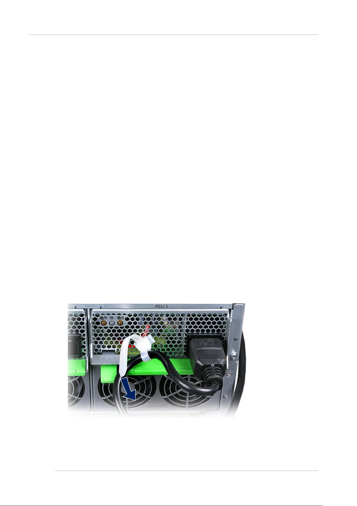
CHAPTER 2 Preparing for Main Unit Installation
2.8 Mounting the Main Unit in a 19-inch Rack
Note
If you also purchased optional modules for installation, such as additional memory modules or PCI Express cards, first
confirm that the main unit functions normally before mounting the optional modules in the main unit.
2.8 Mounting the Main Unit in a 19-inch Rack
The PRIMEQUEST2000 series server is mounted for use in a 19-inch rack. For details on mounting, see Appendix A
Racks in the PRIMEQUEST2000 Series Hardware Installation Manual (C122-H007EN).
2.9 Connecting the Power Cables
This section describes how to connect the power cables.
You need to connect the power cables to outlets with ground terminals.
Remark
The main unit and PCI_Box are designed to operate with a power supply facility that supports grounded wiring. Do not
connect the main unit and PCI_Box to a power supply facility that does not provide grounded wiring. To determine the type
of power su pply in your building, contact the building manager or a qualified electrician.
Operations
1. Confirm with an engineer specializing in electricity that the input power satisfies power requirements. For details on
the power requirements, see 1.3 Installation Specifications in the PRIMEQUEST2000 Series Hardware Installation
Manual (C122-H007EN).
2. Confirm that the power cables are connected to the AC inlets of the main unit and PCI_Box. Also confirm that the
power cables are secured with the AC cord clamps for the AC inlets on the main unit.
- The cable is passed through the circle of release Thailand.
- Release tie is tightened and the power cable is fixed. The insulation connector is mistaken from t he serv er and
does not come off.
Remark
6
Page 30

CHAPTER 2 Preparing for Main Unit Installation
2.9 Connecting the Power Cables
Release tie can be detached by bending it with the choke end of the zip tie.
3. Group all the cables that run outside the main unit and PCI_Box into power cables and signal cables, and secure
them firmly to the cable holders of the 19-inch rack with cable ties.
4. Confirm that the AC power breaker is off. Then, connect the power cables to AC power. For details on the power
cable connections, see “2.4.2Facility power requirements and characteristics”.
FIGURE 2.1 Power cable socket location s (PRIMEQUEST2000 Series)
FIGURE 2.2 Power cable socket location s (PCI_Box)
7
Page 31

CHAPTER 3 Work before Operating System Installation
3.1 Before Starting Setup
Work before Opera ting Syst em CHAPTER 3
Installation
This chapter descri bes the wo rk that mus t be done before yo u install the operati ng system on the PRI MEQUEST 2000
series and setting of actual operation and various setup works.
3.1 Before Starting Setup
This section describes the items necessary to predetermine before the setup.
3.1.1 MMB Settings
It is necessary to predetermine the following items to configure MMB.
- IP address, hostname, subnet mask, and gateway address
- IP address of the PC used as the MMB console (referred to below as the MMB console PC)
- ID for MMB User Account
- PRIMEQUEST 2000 series system name (Also used as the system name for SNMP)
- Management LAN environment
For details on setting of MMB, see “3.3 Connection and Setting of MMB”.
Note
The management LA N, remote maintenance LAN and an y other LAN must be configured as ne tworks with different
subnet masks.
3.1.2 Partition Settings
To construct multiple partitions, following items should be predetermined.
- Number of partitions
- Name of Partition
- Configuration of Partition
- Home SB
For details on setting of partition, see “3.4 Partition Configuration”
If partition name and host name of the operating system installed on the partition are the same, operations management of
partition becomes easier.
Note
- For 2400E/2800E Model
- In case PCI Address Mode is set to PCI Segment Mode, PCI ROM Priority parameter in BIOS menu must be set
"EFI Compatible ROM" if RAID disk drives including HDD and SSD are to be mounted in Non Home SB.
- In case PCI Address Mode is set to PCI Segment Mode, Legacy OS installation to H DD/SS D on SB is possible
only in Home SB.
- In case PCI Address Mode is set to PCI Segmen t Mode, Legac y OS boot ing from HDD/SSD on SB is possible
only in Home SB.
3.2 System Startup
Power control required to startup the system is described in this section.
In case of not being turned on the main power supply of the main unit, follow the procedure described below.
8
Page 32

CHAPTER 3 Work before Operating System Installation
3.3 Connection and Setting of MMB
3.2.1 Power-on/off of main unit
Power-on/off of main unit is described.
Power on
The procedure to turn on the main power supply of the main unit is described below.
(Ignition)
When over current is detected and the power is cut off by tripping the breaker of the AC power or optional power
distribution box, there is a possibility that failure, such as short circuit occurring in the main unit. In such case, contact to
your sales representative or field engineer without turning on the power supply again.
Note
- When the power supply is turned on again after removing the power cable from the AC Inlet, connect the power cable
The procedure to turn on the main power supply of the main unit is described below.
1. Connect the power cable to the AC inlet of the main unit.
2. Connect to AC power or optional power distribution box.
3. Turn on the power supply by turning on the circuit breaker of AC power.
Power off
The procedure to turn off the main power supply of the main unit is described below.
(Data corruption)
Turn off the main power supply of the main unit after confirming that System Power LED of Operator Panel (OPL) Is turned
off. If the main power supply is turned off while the System Power LED of the OPL is ON, there is a risk of the data being
corrupted.
The procedure to turn off the main power supply of the main unit is described below.
1. Turn off the power supply of the main unit. For details, see “7.1.2 Power OFF of the partition”.
2. Confirm that the System Power LED of OPL is turned off.
3. Remove the power cable connected to power distribution box.
after ten se conds or more.
For details on the power cable connection, see “2.9 Connecting the Power Cables”.
After removing the power cable, follow the procedure sequentially from step 1 to turn on the power supply again
Remark
When the System Power LED of OPL is turned on, it is in the state that power supply cannot be turned off. When
Alarm LED is turned on , contact to your sales representative or field engineer.
3.3 Connection and Setting of MMB
The MMB has LED displ ay or provides view for server maintenance or adm inistration that the field engineer constructs the
environment for testing and test program is executed. Therefore, it is necessary to reconfigure MMB from test environment
to actual operating environment. Skip the steps for items already set by field engineer.
After MMB connection, implement following steps by using MMB Web-Ul ( Web User Interface).
- User account registration
- Security setting
9
Page 33

CHAPTER 3 Work before Operating System Installation
Procedure
Item
Description
Refer to
1.
Connection of MMB
console PC
Connect the MMB console PC to set up
the environment for actual operation.
3.3.1 Connecting the MMB
console PC
2.
Initial setting of MMB
Initialize MMB settings before setting
actual operation.
3.3.1 Connecting the MMB
3.
Connection setting of
environment
The MMB is set for a test connection.
actual operation.
3.3.3 Setting of Connection for
4.
Login to MMB
Log in to the MMB.
Web-UI window for reference.
3.3.4 Login to MMB
5.
Network setting of actual
The MMB is set for testing purposes,
operation mode.
3.3.6 Network set up of MMB
3.3.9 Set up of Alarm E-Mail
6.
Various initial settings of
Various initial settings of MMB are implemented.
see “3.5 Storage of the configuration information”.
3.3.10 Registration of User
3.3 Connection and Setting of MMB
- Time setting
Implement following procedure of connection and setting of MMB.
TABLE 3.1 Flow of connection and setting of MMB
up the connection environment for
actual operating
operation
MMB
Since all the screensh ots in this manual are examples, dependin g on the configuration, these may diffe r from the actual screen
displays.
Set up the connection environment for
There is also a description of the MMB
so configure the network and Web
servers for actual operation. Make the
required settings appropriate to your
-Registration of user account.
-System name setting
-Date/ Time setting
It is recommended to take the back up of information
of the settings when the initial settings are completed.
For details on the back-up of information which is set,
console PC
Actual operating Environment
3.3.5 Web-UI Window View
3.3.7 Set up of telnet
3.3.8 Configuration of DNS
server
Account
3.3.11 Setting of System
Name
3.3.12 Setting of Date and
Time
10
Page 34

CHAPTER 3 Work before Operating System Installation
External interface
Quantity
Remark
RS232C(COM Port)
1
Used by the field engineer when setting-up the device. It does not use in
LAN 1000Base- T
2
User port
LAN 100Base-TX
2
Maintenance
-[REMO TE]: REM CS Por t
Setting item
Value
Bit/ second
19200
Data bit
8
Parity
No
Stop bit
1
Flow control
No
Emulation
VT100
3.3 Connection and Setting of MMB
3.3.1 Connecting the MMB console PC
This section describes the connection of the MMB and MMB console PC.
To reconfigure the environment of the operation, connect the COM port of the MMB console PC and the External interface
RS232C (COM port) of the MMB with RS232C cross cable.
For the mounting location and external interface overview of the MMB, refer to the figure below.
FIGURE 3.1 Exte rnal Views of Mounting Lo cations and External int erface of MMB
TABLE 3.2 External interface of MMB
normal operations.
-[LOCAL] : CE Port
Set the terminal software by using following contents, at the time of connecting COM port,
TABLE 3.3 contents of setting of terminal software
11
Page 35
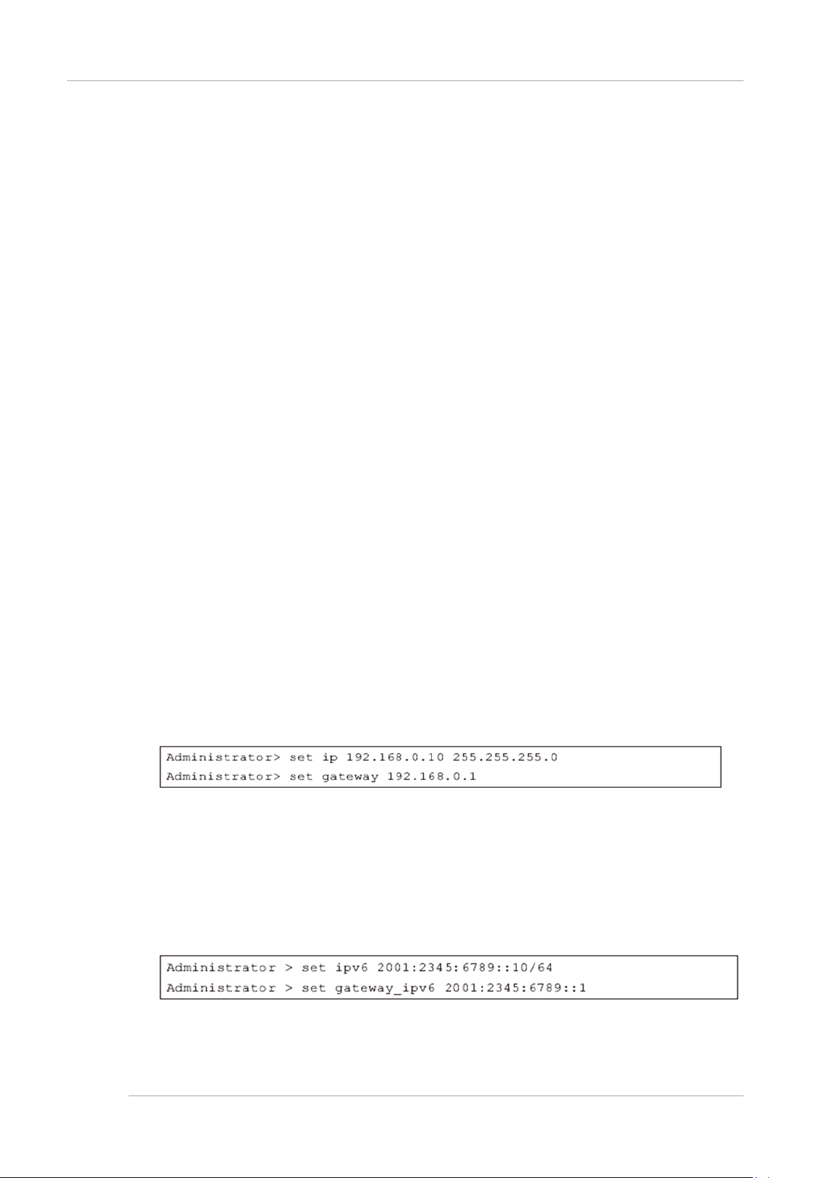
CHAPTER 3 Work before Operating System Installation
3.3 Connection and Setting of MMB
3.3.2 MMB Init ialization.
The procedure for the MMB initialization is described below.
If field engineer initialized the MMB, it is not necessary to implement following procedure.
Operations
1. Turn on the power supply of the main unit.
→ Alarm LED of each unit is turned on while MMB Ready LED is blinking (During initialization).
After MMB Ready LED turns from blinking to lighting, the login prompt is displayed.
2. Once MMB Ready LED is turned on (Initialization complete), confirm that the Alarm LED of each unit has been
turned off.
3. Login to Administration by using terminal software from MMB console PC.
→ When you first log in, you will be asked to change the Administrator password.
4. Set the password.
Note
The password with eight more characters should be set.
Usable character codes are alphanumeric characters ([A-Z] [a-z] [0-9]) and the following symbols
! ” # $ % & ’ ( ) = . ^ ~ ¥ ` [ ] { } : * ; + ? < . > , / _ |
If the entered password is invalid, re-setting of the password is requested.
5. Then set MMB network.
Remark
When IPv4 and IPv6 are operated, both IPv4 and IPv6 are set.
- In case of IPv4
Set the IP Address by using the following commands.
# set hostname <FQDN type host name>
# set ip <IP Address> <netmask>
# set gateway <def ault ga teway I P Addr ess>
# set http enable
Example: In case of IP Address:192.168.0.10/ netmask:255.255.255.0/ gateway:192.168.0.1
- In case of IPv6
Set IP Address by using following commands.
# set hostname <FQDN type host name>
# set ipv6 {auto} <IP Address/Prefix>
# set gateway_ipv6 <default gateway IP Address>
# set http enable
Example: In case of IP Address=2001:2345:6789::10/ Prefix=64/ gateway=2001:2345:6789::1
6. Enable http by set http enable command.
12
Page 36

CHAPTER 3 Work before Operating System Installation
3.3 Connection and Setting of MMB
Web-UI of MMB can be accessed from MMB console PC through LAN.
Remark
Use set https command to enable https.
7. Enable telnet by using set telnet enable command.
8. Set date and time as required.
Use the following commands.
Administrator> set date MMDDhhmm[[CC]YY][,ss]
Example: To set 2013/7/27 as date and 13:10:00 as time
3.3.3 Setting o f Connect ion for A ctual operating Environment
According to the following operations, set the connection environment for the actual operation.
- Set IP address of MMB console PC
- Connect MMB console PC to the User port of the MMB
- Connect external LAN of PRIMEQUEST 2000 series
Setting of IP address of MMB console PC
Set the IP address of the PC used as the MMB console. See the Manual of the PC to be used for the setting method.
Connection of MMB console PC to the user interface of the MMB
Connect the MMB console PC to the use r port #0 of the MMB using LA N cable. Once it is c onnected, commu nication
between MMB console PC and MMB is possible via LAN.
FIGURE 3.2 Location of MMB user port
Connection of External LAN of PRIMEQUEST 2000 Series
Configuration of e xternal LAN con nection of PRIMEQUEST 2 000 series a nd the notes for external LAN connec tion are
described below. C onnection to an exte rnal LAN is recommend ed afte r setting t he security . For de tails on s ecurity, see
“6.5 Set up of security”
.
13
Page 37

CHAPTER 3 Work before Operating System Installation
Conditions
Required settings
When using the switching hub which supports the
external switch
Prevent circulatory prevention function to [disable] Spanning Tree Protocol
It is necessary to set the firewall and mail server in such a way that
Connection format is as given below.
from the external switch of the
Service Installation Manual (C122-E180EN).
3.3 Connection and Setting of MMB
FIGURE 3.3 Network Configuration and IP Address of Management LAN
Ports for managin g MMB#0 and MMB#1 are connect ed to the externa l switchi ng hub device using a LAN c able. At the
same time MMB console PC is also connecte d to the external switching hub device. Physical IP addres s and Virtual IP
address of MMB#0 a nd MM B#1 are set in identical subnet.
- Physical IP Address (In the above figure, MMB#0=192.168.1.100, MMB#1=192.168.1.101)
- Virtual IP Address (In the above figure, 192.168.1.102)
For external connection (W eb browser, Terminal for Maintenance, REMCS, etc.), communication is done by vir tual IP
address.
TABLE 3.4 Settings required for connecting external LAN
circulatory prevention function (Spanning Tree
Protocol or the domain Separation, etc.) in the
When the data given below corresponds to any of
the category-
-Destination server becomes external server which
is passed through the firewall.
-Use a mail server which restricts the IP address.
For REMCS connection
of connection por t of switching hub and the main unit o r to set Domain
Separation ‘ON’.
physical IP address packets of MMB #0 and MMB#1 can pass through.
- When connecting to internet:
Connect REMCS po rt to the external switchi ng hub. Or connect to the
center by restricting the firewall
management port.
- When connecting to P-P
Connect each REMCS port of MMB of MMB#0 and MMB#1 to the Dialup route directly.
For details on REMCS linkage, see PRIMEQUEST 2000 series REMCS
Remark
- Packe ts a re transm itted f rom MMB in “NTP”, “Ala rm E-Mail”, and “REMCS” . When bo th the ph ysical IP add ress and
the virtual IP address of MMB are set, the tra nsmissio n sou rce I P addr ess of packe t is cons idered as the p hysica l IP
address of the MMB.
14
Page 38
CHAPTER 3 Work before Operating System Installation
http://nodename:adminport
http://nodename:adminport/login.cgi (In case of Windows Server 2012 and Windows Server 2008 R2)
SSL
https://nodename:adminport
Above-mentioned nodename: adminport is described in following format.
case of SSL)
3.3 Connection and Setting of MMB
- Physical IP address of MMB is also used in PRIMECLUSTER linkage.
3.3.4 Login to MMB
The method of login to the MMB is described below.
Login/ Logout in MMB Web-UI
The procedure of Login/Logout for MMB Web-UI is described below.
Specify any of th e follow ing t o login t o Web-UI.
- Virtual IP Address
- Fully Qualified Domain Name (FQDN) corresponding Virtual IP Address
Note
- MMB Web-UI sup ports the fol lowing brows ers. Note that, if the browser other than this is used, Web UI window may
not display correctly.
- Internet Explorer 9 onwards
- Firefox 20 onwards
- Do not multiple login by using W eb-UI from one MMB console PC to PRIMEQUEST 2000 series (Also includes
multiple login with the same user name). If multiple login is done, the following phe nomenon may occur by the typ es
and version of a browser to be operated. Moreover, do not multiple login by using multiple tabs.
- The operation authority of the user logged in previously with Web-UI might change to the operation authority of the
user who logs in later.
- When one Web-UI is logged out, all Web-UIs might be logged out.
Remark
To specify the FQDN, the DNS server should be set in the MMB console PC
For details on DNS server setting, see “3.3.8 Configuration of DNS server”,
Login
1. Start th e Web brow ser.
Remark
Enable JavaScript and Download in the browser setting.
2. Enter next URL.
TABLE 3.5 URL to be entered for Login
Standard
Remark
Nodename: FQDN of MMB or IP Address.
adminport: port number assigned at the management port of the MMB (Default value is 8081 and 432 in
Note
When an https connection is established, a warning message appears because the certificate is not one from
a third-party organization. Ignore it and continue establishing the connection.
3. Since MMB Web-UI login window is displayed, enter user account and password and click on [Login] button.
15
Page 39

CHAPTER 3 Work before Operating System Installation
Username
Administrator
Password
Password set up by the field engineer when setting a device
3.3 Connection and Setting of MMB
FIGURE 3.4 MMB Web-UI [Login] Window
Remark
At the time of initial start-up and if the settings have not been changed, following default user account and password
are applicable.
TABLE 3.6 Default user account/pas sword
● Logout
Click [Logout] on the Navigation Bar.
→ Log out from Web-UI.
3.3.5 Web-UI Window View
For details on W eb-UI window view, see “Ch apter 1 Web-UI Overview” of PRIMEQ UEST 2000 Series User I nterface
Operating Instructions (C122-E176EN)
Remark
When [Read Error] is displayed on Web-UI Window, confirm the contents by referring to “11.2Troubleshooting” of
PRIMEQUEST 2000 series Administration Manual (C122-E175EN). In spite of referring to the manual, if the error cannot
be resolved, recurs, contact repairs inquiry counter or a sales representative.
Before making contact, confirm the model name and serial number shown on the label on the device and communicate the
same.
Basic oper ation s in MMB We b-UI
The flow of basic operations is as follows.
16
Page 40

CHAPTER 3 Work before Operating System Installation
3.3 Connection and Setting of MMB
1. The Menu is selected from Navigation Bar.
→ The Submenu of the selected menu is displayed in the submenu area.
2. The Menu is selected from the submenu.
→ The window corresponding to the selected menu is displayed in the content area.
3. Information displayed on the window is confirmed and set.
When [Apply] Button is clicked, the information is set.
When [Cancel] Button is clicked, the information returns to the previous status.
Note
When Internet Explorer is being used, if the display of dialog box for confirmation of process execution, or the display of
dialog box or for notification of process completion exceeds 2 minute or more, its connection with MMB Web-UI is cut. In
this case, login again to MMB Web-UI.
3.3.6 Network set up of MMB
MMB Network is set up. For the items already set at this time, confirm the setting contents. For the items not set, make the
settings.
Following IP Addresses are set.
- Virtual IP Address used to access Web-UI
- Physical IP Address assigned to the MMB interface.
See “3.5 Storage of the configuration information” for the backup of information which is set
Note
- Set up of MMB Physical I P Address is not required, as long as MMB is not mounte d at the installation location
MMB#1, and PRIMECLUSTER linkage is not performed.
- Log in to ‘Administrator privileges, to set up MMB network.
- When on [Network Interface] wi ndow, if [ Apply] Button is clicked af ter changing [ MMB#0 IP Add ress] or [MMB#1 IP
Address]:
To reflect the settings, the network is temporarily stopped, and Web-UI is cut. It is possible to connect to Web-UI again
by selecting Web-UI menu.
- When Virtual IP Address is changed:
Connection with MMB Web-UI is cut. Re-login is required when MMB Web-UI is to be used.
Remark
When Virtual IP Address is set up:
The Web browser has an access fo r the virtual IP address of PRIMEQU EST 2000 se ries. Therefore, the MMB Web-UI
cannot be accessed by specifying the physical IP address of MMB#0, and MMB#1.
Terminal for maintenance and REMCS can access as against the IP address set in [Maintenance IP Address] of [Network
Configuration]-[Network Interface].
Operations
1. Click [Network Configuration]-[Network Interface].
→ [Network Interface] screen is displayed. For details on [Network Interface] screen, see
‘1.5.2[Network Interface] Menu’ of PRIMEQUEST 2000 series Tool Reference (C122-E177EN).
17
Page 41
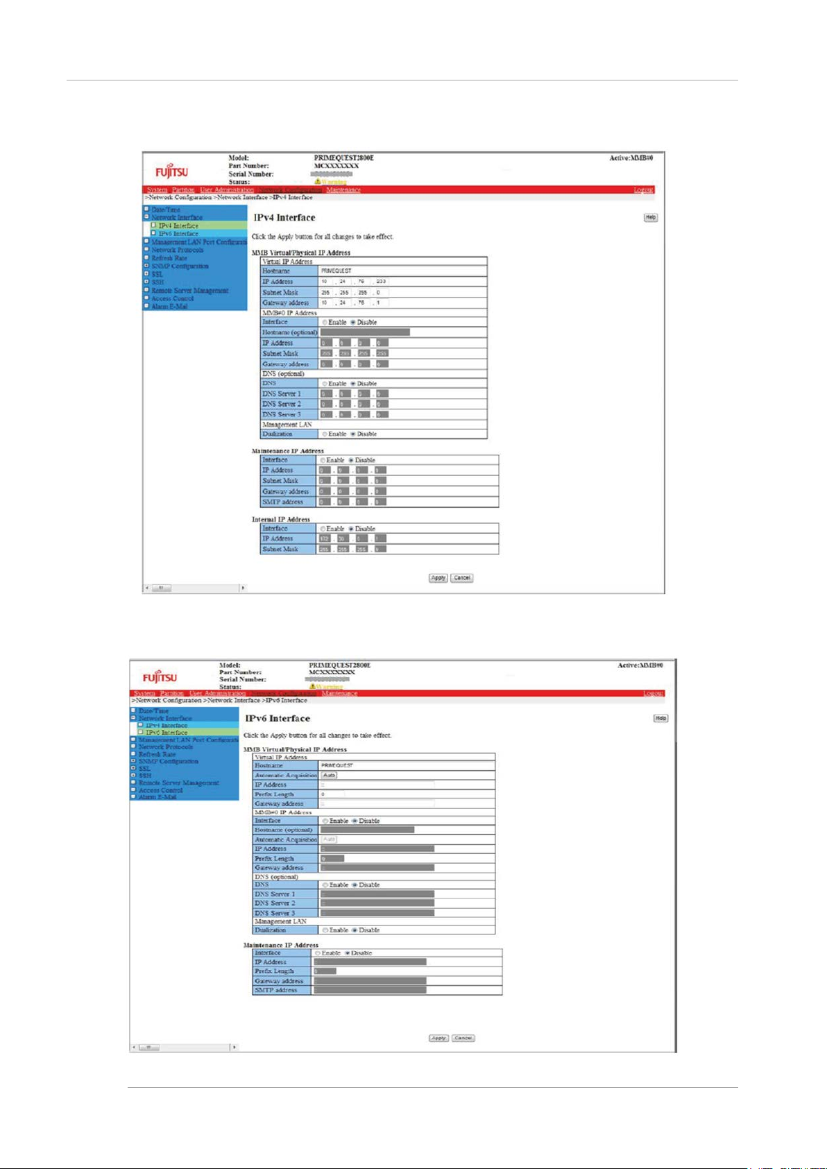
CHAPTER 3 Work before Operating System Installation
3.3 Connection and Setting of MMB
FIGURE 3.5 Example of [IPv4 Interface] Window
FIGURE 3.6 Example of [IPv6 Interface] Window
18
Page 42

CHAPTER 3 Work before Operating System Installation
3.3 Connection and Setting of MMB
2. The values are entered in [IP Address], [Subnet Mask] (*1) of [Virtual IP Address]. Host name is also set up.
*
1: [Prefix Length] is entered at the time of [IPv6]. [Gateway Address] is also entered at the time of [Gateway
Address].
3. Each item is entered by clicking [Enable] for [Interface] in [MMB#0 IP Address] or [MMB#1 IP Address]. Here, the
assigned Physical IP Address is specified.
4. [Apply] button is clicked when the required items are set up.
Notes
If an incorrect value of IP Address is set, MMB Web-UI is not displayed. In that case, the correct value is set by
connecting MMB console PC to the MMB COM port.
Remark
The Physical IP Address and the Virtual IP Address of MMB#0, and MMB#1 are set up in the same subnet.
3.3.7 Set up of telnet
MMB telnet is set up.
See “3.5 Storage of the configuration information” for the backup of set up information.
The following condition must be satisfied in advance when field engineers perform the Maintenance tasks on this product.
- Video Redirection and Virtual Media are available.
For details on how to setup the procedure, see Chapter 1.3.6 [Console Redirection Setup] window in the PRIMEQUEST
2000 Series Tool Reference (C122-E177).
- SSH or Telnet is available.
For details on ho w to setup the procedure, see Chapter 1.5 .4 [Network P rotocols] windo w in the PRI MEQUEST 2000
Series Tool Reference (C122-E177).
Note
To set up telnet, log in to Administrator privileges.
19
Page 43

CHAPTER 3 Work before Operating System Installation
3.3 Connection and Setting of MMB
Operations
1. Click [Network Configuration]-[Network Protocols].
→ [Network Protocols] window is displayed. For details on [Network Protocols] window, see “1.5.4[Network
Protocols] Window” of PRIMEQUEST 2000 series Tool Reference (C122-E177EN).
FIGURE 3.7 Example of [Network Protocols] Window
2. Items of [Telnet] are set.
Note
MMB uses the following fixed port number of TCP/IP. Do not change the following port numbers.
- 623/udp: For RMCP communication
- 664/udp: For RMCP communication
3. Click [Apply] button.
20
Page 44
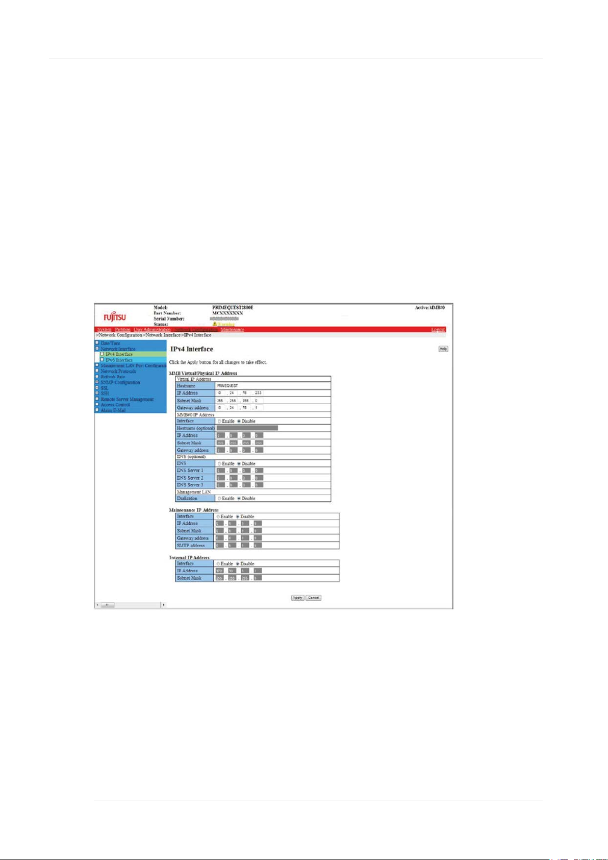
CHAPTER 3 Work before Operating System Installation
3.3 Connection and Setting of MMB
3.3.8 Configuration of DNS server
Only when using a DNS server, set up DNS server.
For the backup of set up information, see “3.5 Storage of the configuration information”.
Note
Log in to Administrator privileges to set up the above-mentioned items.
Operations
1. Click [Network Configuration]-[Network Interface]. Select [IPv4 Interface] or [IPv6 Interface].
→ [IPv4 Interface] or [IPv6 Interface] window is displayed. For details on [IPv4 Interface] or [IPv6 Interface] window,
see “1.5.2 [Network Interface] Menu” of PRIMEQUEST 2000 series Tool Reference (C122-E177EN).
FIGURE 3.8 Example of [IPv4 Interface] Window
21
Page 45

CHAPTER 3 Work before Operating System Installation
3.3 Connection and Setting of MMB
FIGURE 3.9 Example of [IPv6 Interface] Window
2. Click [Enable] of [DNS] in [DNS (optional)], then each item is entered.
3. Click [Apply] button after setting the required items.
22
Page 46

CHAPTER 3 Work before Operating System Installation
3.3 Connection and Setting of MMB
3.3.9 Set up of A larm E-Mail
Set up the following for Alarm E-Mail.
- Whether to notify through E-Mail, when an error occurs during operation.
- Error level and notification destination at the time of notifying.
For the backup of the set up information, see “3.5 Storage of the configuration information”.
Note
To set up the above mentioned items, log in to Administrator privileges ‘.
Operations
1. Click [Network Configuration]-[Alarm E-Mail].
→ [Alarm E-Mail] window is displayed. For details on [Alarm E-Mail] Window, see “1.5.11 [Alarm E-Mail] window” of
PRIMEQUEST 2000 series Tool Reference (C122-E177EN).
FIGURE 3.10 Example of [Alarm E-Mail] Window
2. Enter required items.
Remark
When transmitting [Alarm E-Mail], [From] address to be transmitted to SMTP server is as follows.
- When [Use envelope “from” address] checkbox is on,
The address set up in [From] of [Alarm E-Mail] window becomes [From] a ddress to be transmit ted to SMTP
server.
- When [Use envelope “from” address] checkbox is off (initial set up)
Following [From] address is transmitted to SMTP server according to the format of [Hostname], set up in [Virtual
IP Address]-[Hostname] in [Network Configuration]-[Network In terfac e] wind ow.
- In FQDN format: root@[Hostname]
- Except in FQDN format: root@localdomain.localdomain
Mail address set up in [From], is used as [From] address of the mail to be transmitted to mail receiver ([To]).
- When FQDN is specified in SMTP Server name, DNS Server needs to be set up. DNS S erver can be s et up
23
Page 47

CHAPTER 3 Work before Operating System Installation
3.3 Connection and Setting of MMB
- from [Network Configuration]-[Network Interface].
3. The operation button is clicked depending upon the purpose.
- When the condition for transmission of mail is set up: [Filter] Button
- When the settings are to be enabled: [Apply] Button
- During Test transmission: [Test E-M ail] Butt on
Setting the conditions for transmission of mail
1. To set the conditions for transmitting the mail, click [Filter] button on [Alarm E-Mail] window.
FIGURE 3.11
Example of [Alarm E-Mail Filtering Condition] Window
2. Select required items. When multiple items are selected, each item is AND condition, when multiple options are
selected in each item, it is OR condition.
3. Click [Apply] Button.
24
Page 48

CHAPTER 3 Work before Operating System Installation
3.3 Connection and Setting of MMB
3.3.10 Registration of Use r Account
As an initial set up, user accounts of the required number are registered. The number of maximum registration is 16.
Refer “3.5 Storage of the configuration information” for the backup of set up information.
Operations
1. Click [User Administration] [User List].
→ [User List] window is displayed. For details on [User List] window, see “1.4.1[User List] Window” of
PRIMEQUEST 2000 serie
s Tool Reference (C122-E177EN)
FIGURE 3.12 Example of [User List] Window
2. Click [Add User] button.
→ [Add User] window is displayed. For details on [Add User] window, see “[Add User] Window” of “1.4.1[User List]
Window” of PRIMEQUEST 2000 series Tool Reference (C122-E177EN).
25
Page 49

CHAPTER 3 Work before Operating System Installation
3.3 Connection and Setting of MMB
FIGURE 3.13 Example of [Add User] Window
Remark
In case of changing the user count, click the [Edit User] button on the [User List] and change the recorded contents on the
[Edit User] window.
For details of [Edit User] Window, see “ [Edit User] Window” of “1.4.1 [User List] Window” of PRIMEQUEST 2000 series
T ool Reference (C122-E177EN).
26
Page 50

CHAPTER 3 Work before Operating System Installation
3.3 Connection and Setting of MMB
FIGURE 3.14 Example of [Edit User] Window
3. Input the required items.
4. Click [Apply] button.
27
Page 51

CHAPTER 3 Work before Operating System Installation
3.3 Connection and Setting of MMB
3.3.11 Setting of System Name
Sets the name for system of PRIMEQUEST 2000 series. This name is used as SNMP [System Name].
For the backup of the set information, see“3.5 Storage of the configuration information”.
Operations
1. Click [System] - [System Information]
→ [System Information] window is displayed.
For details on [System Information] window, see “1.2.5 [System Information] Window” of PRIMEQUEST 2000 series
Tool Reference (C122-E177EN).
FIGURE 3.15 [System Information] Window Example
2. Enter [System Name].
3. Click [Apply] button.
28
Page 52

CHAPTER 3 Work before Operating System Installation
3.3 Connection and Setting of MMB
3.3.12 Setting of Date and T ime
The date, time and NTP (In case of NTP server) of the MMB is set
However, occasionally it is already set by the field engineer. If it is already set by the field engineer and if it is not required to
be changed, go to the next setting.
For the backup of the set information, see“3.5 Storage of the configuration information”.
Remark
provides NTP client function . The NTP client function of MMB adjusts the time on the basis of another N TP Server.
MMB
For a stable NTP operation, specify multiple NTP Servers from each NTP client (In case of RHEL more than three servers
are recommended).
Operations of [Date/ Time] window
1. Click [Network Configuration] - [Date/Time].
→ [Date /Time] window is displayed. For details on [Date /Time] window, see “1.5.1 [Date/Time] window” of
PRIMEQUEST 2000 series Tool Reference (C122-E177EN).
FIGURE 3.16 [Date/ Time] Window Example
2. Input required items.
3. Click [Apply] Button.
Operations of [Management LAN Port Configuration]
1. Click [Network Configuration] - [Management LAN Port Configuration].
→ [Management LAN Port Configuration] window is displayed. For details of [Management LAN Port Configuration]
window, see “1.5.3 [Management LAN Port Configuration] window” of PRIMEQUEST 2000 series Tool Reference
(C122-E177EN).
29
Page 53

CHAPTER 3 Work before Operating System Installation
3.3 Connection and Setting of MMB
FIGURE 3.17 [Management LAN Port Configuration] Windows Example
2. Enter required items.
3. Click [Apply] Button.
30
Page 54

CHAPTER 3 Work before Operating System Installation
3.4 Partition Configuration
3.4 Partition Configuration
This section describes partition configuration. PQ2400E and 2800E are available for these func tions. Power off, power on
for every partition is required to re flect the configuratio n change of partition. All screenshots are display examples. The
displayed contents differ according to the system configuration.
3.4.1 Setting the pa rtition configuration
This section describes addition and removal of operations of SB and IOU.
Adding o f SB/IO U
SB and IOU can be added to the partition.
Operations
1. Click [Partition] - [Partition Configuration]
→ [Partition Configuration] window is displayed. For details of [Partition Configuration] window, see “1.3.3 Partition
Configuration] window” of PRIMEQUEST 2000
series Tool Reference (C122-E177EN).
FIGURE 3.18
[Partition Configuration] Window Example
2. Click the radio button of partition number in which one SB or one IOU is added
3. Click [Add Unit] Button
31
Page 55
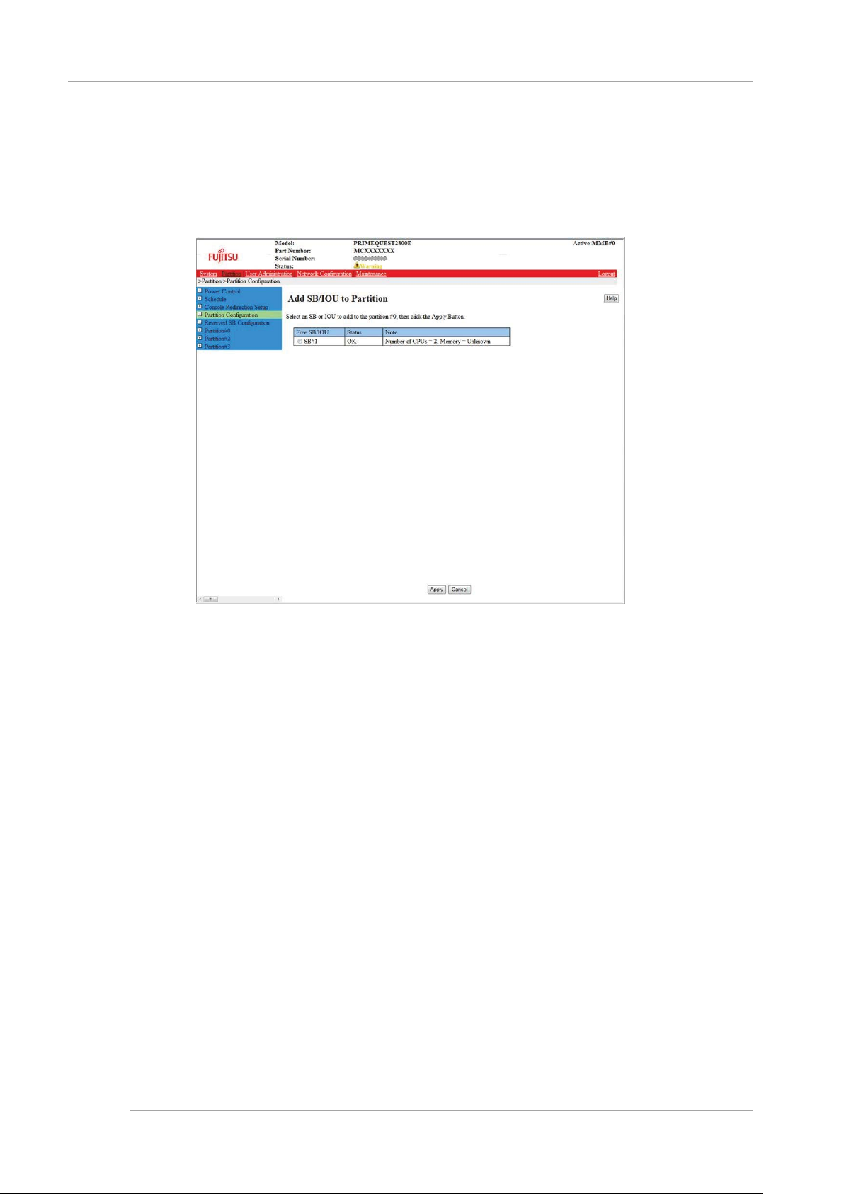
CHAPTER 3 Work before Operating System Installation
3.4 Partition Configuration
→ [Add SB/IOU to Partition] window is displayed. Free SB and IOU are displayed in the list. For details of [Add
SB/IOU to Partition] window, see “ [Add SB/IOU to Partition] window] of “1.3.3 [Partition Configuration] window” of
PRIMEQUEST 2000 series Tool Reference (C122-E177EN).
.
FIGURE 3.19 Example of [Add SB/IOU to P artitio n] Wind ow
4. Click the radio button of one SB or one IOU to add it to the partition.
5. Only one SB or one IOU can be selected by one operation.
6. Click the [Apply] button.
→Confirmation dialogue box is displayed.
7. Click [OK] button.
→The selected one SB or one IOU is added in the partition.
Repeat procedure 2~6 until you have added all the required SBs or IOUs.
Removing of SB and IOU
This section describes the method of removing the SB or IOU from the partition.
Remark
Y ou cannot remove a SB or IOU while the operating system on the target partition is running. Remove the SB or IOU while
the partition power is in the standby status.
Operations
1. Click [Partition] - [Partition Configuration]
→ [Partition Configuration] window is displayed. For details of [Partition Configuration] window, see “1.3.3 Partition
Configuration] window” of PRIMEQUEST 2000
series Tool Reference (C122-E177EN).
32
Page 56

CHAPTER 3 Work before Operating System Installation
3.4 Partition Configuration
FIGURE 3.20 [Partition Configuration] Window Example
2. Click the radio button of the partition number from which the SB/IOU is to be remov ed.
3. Click the [Remove Unit] button.
[Remove SB/IOU from Partition] window is displayed. SB and IOU are displayed in the list. The SB and IOU are
incorporated in the partition that is selected by procedure 2.
For details of [Remove SB/IOU from Partition] window, see “[[Remove SB/IOU from Partition] window] of “1.3.3
[Partition Configuration] window” of PRIMEQUEST 2000 series Tool Reference (C122-E177EN).
33
Page 57

CHAPTER 3 Work before Operating System Installation
3.4 Partition Configuration
FIGURE 3.21 Example of [Remove SB/IOU from Partition] Window
4. Click the radio button of one SB or one IOU which is to be removed from the partition.
Only one SB or one IOU can be selected by one operation.
5. Click the [Apply] button.
→ A confirmation dialogue box is displayed.
6. Click [OK] button.
→The selected one SB or one IOU is removed from the partition and is free.
3.4.2 Setting the Home SB
One SB in each partitio n is set as the Home SB. The SB tha t is initially added in every partitio n is automaticall y set as
Home SB.
Moreover when Home SB is removed, the SB having the smallest number among the SB that configures the partition and
which is not degraded is automatically set as Home SB.
In Home SB, the USB port and the VGA port can be used as external connectors.
When the Home S B has to be change d, it is specified by Web-UI. For details of Home SB, see “5.9 Home SB” of
PRIMEQUEST 2000 series Product Description (C122-B025EN).
Remark
The Windows license needs to be verified depending on the integration of the SB and the enable kit. For details, see “
License verification based on the integration of SB and enabling kit” of “3.4 component expansion” of PRIMEQUEST 2000
series Administration Manual (C122-E175EN).
Operations
1. Click [Partition] - [Partition Configuration] - [Home]
→ [Partition Home] window is displayed. For details of [Partition Home] window, see “[Partition Home] window” of
“1.3.3 [Partition Configuration] window” of PRIMEQUEST 2000 series Tool Reference (C122-E177EN).
34
Page 58
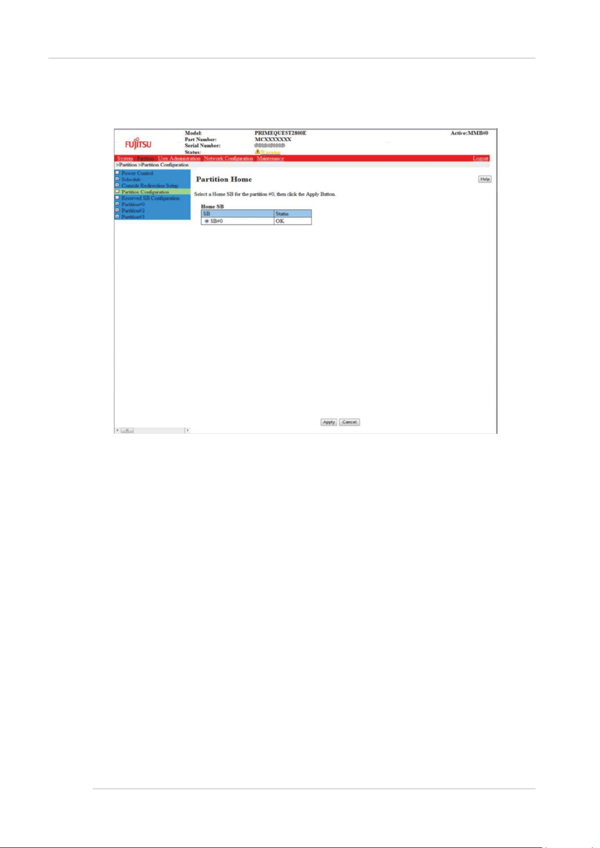
CHAPTER 3 Work before Operating System Installation
3.4 Partition Configuration
FIGURE 3.22
Example of [Partition Home] Window
2. Selecting a SB as the Home SB for the partition.
3. Click the radio button for the selected Home SB.
Remark
As long as SB is set as Home even if it is not mounted, it is displayed as gray out. The radio button on the row which
is shown as grayed out can be changed to the radio button on the row which is not shown as grayed out. Once the
radio button is disabled from gray out display, the original radio button cannot be selected again.
4. Click [Apply] button.
→ A confirmation dialogue box is displayed.
Note.
At the time of clicking the [Apply] button, if the power supply for the partition has been turned on, Home cannot be
changed. A warning dialogue box is displayed.
5. Click [OK] button to continue the process, click [Cancel] button to cancel the process.
Returns to [Partition Configuration] window.
35
Page 59
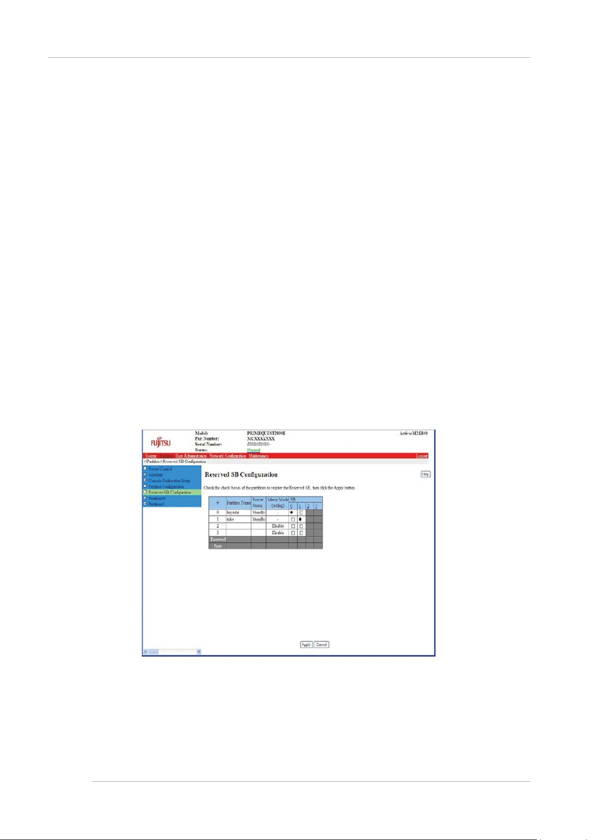
CHAPTER 3 Work before Operating System Installation
3.4 Partition Configuration
3.4.3 Setting of Reserved SB
If hardware failure occurs in the SB which is added in the partition and it may be necessary to remove the SB. Reserved
SB is an SB which is newly added in the partition instead of removal of SB.
To configure Reserved SB in partition, following points should be considered. SB which is not added in the specified
partition can be defined as Reserved SB.
The following SB
- SB in free status
- SB added in other partitions
- SB defined in Reserved SB of other partitions
For details of Reserved SB, see “3.2.3 Reserved SB” of PRIMEQUEST 2000 series Administration Manual (C122E175EN).
Remark
- Flexible I/O mode configuration is required to implement the Reserved SB.
- Windows license verification is required depending on the com bination of SB and enables kit. For details “Activation
depending on the combination of SB and enabl e kit” of “3 .4 Component extension” of PRIMEQUEST 2000s Series
Administration Manual (C122-E175EN).
Operations
1. Click [Partition]-[Reserved SB Configuration]
[Reserved SB Configuration] window is displayed. Check box is displayed vertically in the free status SB column
or the column of SB which is defined as Reserved SB. For details of [Reserved SB Configuration] window, see “1.3.5
[Reserved SB Configuration] window” of PRIMEQUEST 2000 series Tool Reference (C122-E177EN).
is not added in the partition.
FIGURE 3.23
2. Check the checkbox of the partition to be reserved in SB column.
3. Click [Apply] button.
Remark
Uncheck the checkbox on [Reserved SB Configuration] window to free the reserved SB.
Example of [Reserved SB Configuration] Window
36
Page 60

CHAPTER 3 Work before Operating System Installation
3.4 Partition Configuration
Reserved SB configuration conditions
Reserved SB has following conditions.
- Reserved SB cannot be configured in the partition that uses TPM functions.
- An SB installed with 32GB DIMM cannot be configured on a Reserved SB of the partition, which is configured on the
SB installed with memory having various capacities (8GB, 16GB, 64GB DIMM).
- An SB with 64GB DIMM cannot be configured on an Reserved SB of the partition which is configured on the SB
installed with memory having various capacities (8GB, 16GB, 32GB DIMM).
If the above menti oned mou nting c onditions a re no t fulfilled , a messa ge dial ogue bo x of “Unable to register the specified
SB#x as a Reserved SB due to the home SB is TPM enabled.” would be dis played and the Reserved SB configu ration
would be prevented.
Memory Operation Mode may be changed after switch over of faulty SB to Reserved SB if:
- Reserved SB is configured for partition of one SB, and
- The Reserved SB does not fulfill requirements for Memory Operation Mode
In that case, a confirmation dialogue box of “The DIMM does not satisfy requirements of the Mirror Mode. If you register the
specified SB%s as a Reserved SB, the Mirror Mode will be disabled when switching to s pecified SB. Are you sure to
continue?[Y/N]” would be displa yed when configuring t he Reserved SB. Reserved SB fo r partition of multi ple SB must
follows conditions below. This is applicable for PRIMEQUEST 2800E.
- Mount two CPUs for Reserved SB of the partition.
- Reserved SB fulfills Memory Operation Mode requirements same as switching source partition.
- Mount the same type of CPU with the SB that configures partition for Reserved SB.
If the above mounting conditions are not fulfilled, a message dialogue box of “Unable to register the specified SB#x as a
Reserved SB because the DIMM does not satisfy requirements of Mirror Mode.” is displayed and Reserved SB
configuration would be prevented.
Points to be considered for Windows
When switching to Reserved SB in the partition operating on Windows,, Windows operating system is not activated at the
time of initial start-up after switching to Reserved SB.
Configure the Reserved SB in partition operated by Windows so that Windows can be configured automatically.
For configuration details, see “11.4.3 Settings of Dump environment (Windows)” of PRIMEQUEST 2000 series
Administration Manual (C122-E175EN). Turn on the [Start-up automatically] check box of [Start-up and recover] dialogue
box.
Consider the time required for reactivation, when the operation is stopped during SB failure resulting from the above
mentioned reasons.
Total 2 times are required for reactivation at the time of initial start-up and switching to Reserved SB.
However, if below mentioned prevention procedure is executed, reactivation request can be controlled.
Windows re-start prevention procedure
The request of reactivation can be controlled by recognizing Reserved SB to the PRIMEQUEST 2000 series in advance.
Execute the following procedures for all Windows partitions.
If this prevention procedure is executed, reactivation is not demanded, when switched to Reserved SB due to SB failure.
1. Shut down the partition after completing Windows installation.
2. One SB is removed from the partition by using MMB Web-UI. When multiple SBs are installed, any one out of them
can be removed.
3. Add SB for Reserved SB to the partition.
For details, see “ Built in SB and IOU” of “3.4.1 Setting the partition configuration”.
4. Turn on the power supply of partition and start the Windows.
5. Login by Administrator privileges‘. Reactivate according to the instructions, if the message requesting the reactivation
is displayed.
6. Shut down after Windows is reactivated.
7. Remove the SB for Reserved SB, which was added in procedure 3, from the partition by using MMB Web-UI.
8. Add SB removed from procedure 2 to the partition.
Points to be considered for VMware
When switched to Reserved SB by the partition wherein ESX is in operation, the guest operating system may not be
activated at the time of the initial start after switching to the Reserved SB.
37
Page 61

CHAPTER 3 Work before Operating System Installation
3.4 Partition Configuration
Set the items of automatic activation of guest operating system and BlueScreenTimeout while configuring the Reserved SB
in the partition wherein ESX is in operation.
For example, to reset the items 20 seconds after a panic occurs in the ESX host, set “20” to BlueScreenTimeout.
Remark
If items are not reset, when ESX host becomes panic, set “0” to BlueScreenTimeout.
Setting method of BlueScreenTimeout
Execute BlueScreenTimeout settings from vSphere Client.
1. [Configuration] tab of host is opened on vSphere Client. Click [Detailed settings] of [Software] column.
FIGURE 3.24 Settings of BlueScreenTimeout ([Configuration] tab)
2. [Detailed settings] window is opened. Click [Misc] in left side column.
3. Each parameter is displayed in right side frame. BlueScreenTimeout value is set to [Misc. BlueScreenTimeout].
38
Page 62

CHAPTER 3 Work before Operating System Installation
3.4 Partition Configuration
FIGURE 3.25 Settings of BlueScreenTimeout (Settings of [Misc])
For details on vSphere Client, see the manual of VMware.
3.4.4 Partition n ame se ttings
Administrator privileges are required to set partition name. Fujitsu recommends using host name for partition name.
Operations
1. Click [Partition]-[Partition Configuration]
39
Page 63

CHAPTER 3 Work before Operating System Installation
3.4 Partition Configuration
FIGURE 3.26 Example of [Partition Configuration] Window
Remark
Above mentioned window is used in case of maximum configurations.
2. Select partition which sets the partition name and enter the partition name in [Partition name] cell.
Remark
The name can be input up to 16 characters. The characters that can be used are as follows.
[0-9], [a-z ], [A-Z], half-width space, # (Sharp), _ (Underline), and – (Hyphen)
3. Click [Set Partition Name] button.
Name is set for the selected partition.
3.4.5 Various mode settings
Dynamic Reconfiguration, Memory operation mode, and Hyper Threading Mode, etc. of the partition are set. Setting items
are set by MMB Web-UI and UEFI. Following table lists the setting items and screen transition.
For details on the respective settings, see PRIMEQUEST 2000 series Tool Reference (C122-E177EN)
40
Page 64

CHAPTER 3 Work before Operating System Installation
Refer to[PRIMEQUEST 2000 series Tool
Reference] (C122-E177EN)
Setting operating system
installation Mode
MMB Web-UI-[Partition]-[Partition#x][Mode]
1.3.8[Partition #x] Menu
[Mode] Window
Memory Operation Mode
MMB Web-UI-[Partition]-[ Partition#x][Mode]
1.3.8[Partition #x] Menu
[Mode] Window
PCI Address Mode
MMB Web-UI-[Partition]-[ Partition#x][Mode]
1.3.8[Partition #x] Menu
[Mode] Window
Dynamic Reconfiguration
MMB Web-UI-[Partition]-[ Partition#x][Mode]
1.3.8[Partition #x] Menu
[Mode] Window
TPM
MMB Web-UI-[Partition]-[ Partition#x][Mode]
1.3.8[Partition #x] Menu
[Mode] Window
Assignment of I/O space
UEFI-[Device Manager]-[I/O Space
Assignment Configuration]
3.4.2[I/O Space Assignment
Configuration] Menu
Hyper-threading
UEFI-[Device Manager]-[CPU
Configuration]
3.4.4 [CPU Configuration] Menu
CPU Active Cores
UEFI-[Device Manager]-[CPU
Configuration]
3.4.4 [CPU Configuration] Menu
Hardware Prefetcher
UEFI-[Device Manager]-[CPU
Configuration]
3.4.4 [CPU Configuration] Menu
Adjacent Cache Line Prefetch
UEFI-[Device Manager]-[CPU
Configuration]
3.4.4 [CPU Configuration] Menu
DCU Steamer Prefetcher
UEFI-[Device Manager]-[CPU
Configuration]
3.4.4 [CPU Configuration] Menu
DCU Ip Prefetcher
UEFI-[Device Manager]-[CPU
Configuration]
3.4.4 [CPU Configuration] Menu
Execute Disable Bit
UEFI-[Device Manager]-[CPU
Configuration]
3.4.4 [CPU Configuration] Menu
Intel Virtualization Technology
UEFI-[Device Manager]-[CPU
Configuration]
3.4.4 [CPU Configuration] Menu
Intel (R) VT-d
UEFI-[Device Manager]-[CPU
Configuration]
3.4.4 [CPU Configuration] Menu
Power Technology (*3)
UEFI-[Device Manager]-[CPU
Configuration]
3.4.4 [CPU Configuration] Menu
Enhanced SpeedStep (*1)
UEFI-[Device Manager]-[CPU
Configuration]
3.4.4 [CPU Configuration] Menu
Turbo Mode (*1)
UEFI-[Device Manager]-[CPU
Configuration]
3.4.4 [CPU Configuration] Menu
Energy P erfor manc e
UEFI-[Device Manager]-[CPU
Configuration]
3.4.4 [CPU Configuration] Menu
P-State Coordination
UEFI-[Device Manager]-[CPU
Configuration]
3.4.4 [CPU Configuration] Menu
CPU C3 Report
UEFI-[Device Manager]-[CPU
Configuration]
3.4.4 [CPU Configuration] Menu
CPU C6 report
UEFI-[Device Manager]-[CPU
Configuration]
3.4.4 [CPU Configuration] Menu
CPU C7report
UEFI-[Device Manager]-[CPU
Configuration]
3.4.4 [CPU Configuration] Menu
Package C State limit
UEFI-[Device Manager]-[CPU
Configuration]
3.4.4 [CPU Configuration] Menu
QPI Link Frequency Select
UEFI-[Device Manager]-[CPU
Configuration]
3.4.4 [CPU Configuration] Menu
Frequency Floor Override
UEFI-[Device Manager]-[CPU
Configuration]
3.4.4 [CPU Configuration] Menu
Perfmon and DFX devices
UEFI-[Device Manager]-[CPU
Configuration]
3.4.4 [CPU Configuration] Menu
Commit Changes and Exit
UEFI-[Device Manager]-[CPU
Configuration]
3.4.4 [CPU Configuration] Menu
Discard Changes and Exit
UEFI-[Device Manager]-[CPU
Configuration]
3.4.4 [CPU Configuration] Menu
3.4 Partition Configuration
TABLE 3.7 Setting of Various modes
Setting item Screen transition
41
Page 65

CHAPTER 3 Work before Operating System Installation
3.4 Partition Configuration
Note
- Confirm the I/O space is allocated in the SAS device (SAS card, RAID card, RAID card in DU or RAID card in SB) of a
relevant partition.
Further, also confirm the allocation of the I/O space to the FC card, onboard LAN an d LAN Car d (Only the card for the
boot passing), while installing on the SAN storage device.
SAS device is displayed as “Device: SAS", and the FC device is displayed as “Device: Fibre". When I/O space is not
allocated, operate [I/O Space Assignment Configuration] menu and remove the allocation of LAN and fibre channel.
However, do not remove the allocation of I/O space for the FC card onboard LAN and LAN Card used for installation,
when the operating system is installed for the storage in SAN environment.
- Confirm whether the Boot device used in the relevant partition is recognized in the UEFI. For confirmation, see
"3.3[Boot Manager] menu" of PRIMEQUEST 2000 series Tool Reference (C122-E177EN). Identify the Boot device by
operating the [Boot Manager] menu when the Boot device is not recognized by the UEFI.
- A confirmation dialo g box is displayed, When th e DIMM c onfiguration mism atches Reserved SB and th e partition,.
When switched to Reserved SB, warning message containing the reaso ns for releasing Memor y Operation Mode is
shown and confirm whether to continue the settings.
For details on [Mode] window, see “ [Mode] window” of “1.3.8 [Partition#x] menu” of PRIMEQUEST 2000 series Tool
Reference (C122-E177EN).
3.4.6 Settings of Console Redirection
When operating system is installed remotely, it is necessary to set Console Redirection. Set the Console Redirection to the
subnet same as management LAN.
[IPv4 Console Redirection Setup] window
1. Click [Partition] - [Console Redirection Setup] - [IPv4 Console Redirection Setup] window.
[IPv4 Console Redirection Setup] window is displayed. For details on window, see “1.3.6 [Console Redirection
Setup] window” of PRIMEQUEST 2000 series Tool Reference (C122-E177EN).
42
Page 66

CHAPTER 3 Work before Operating System Installation
3.4 Partition Configuration
FIGURE 3.27 Example of [IPv4 Console Redirection Setup] Window
2. Set IP address and subnet mask to access Console Redirection LAN for IPv4
3. Enable video redirection and virtual media respectively.
4. Click [Apply] button.
Note
After installation, disable the functions not used.
[IPv6 Console Redirection Setup] window
1. Click [Partition] - [Console Redirection Setup] - [IPv6 Console Redirection Setup] window.
[IPv6 Console Redirection Setup] window is displayed. For details on window, see “1.3.6 [Console Redirection
Setup] window” of PRIMEQUEST 2000 series Tool Reference (C122-E177EN).
43
Page 67

CHAPTER 3 Work before Operating System Installation
3.4 Partition Configuration
FIGURE 3.28 Example of [IPv6 Console Redirection Setup] Window
2. Set IP address and the prefix length to access Console Redirection LAN for IPv6. When it is set automatically, IP
address and the prefix length is acquired by clicking on [Auto] button.
3. Enable video redirection and virtual media respectively.
4. Click [Apply] button.
3.4.7 Power OFF and ON of the partition
Power OFF and power ON are required for each partition to reflect the configuration change in the partition. For the details
of Power OF F and pow er ON, s ee CHAPTER 7Power ON and OFF of the partition”.
Remark
When the console is connected to the partition, processing continues until [UEFI] window is displayed after completion of
POST (Power On Self Test) and then it stops.
3.4.8 Confirmation of partition information
The status of the partition and the partition related information is displayed.
The partition configuration of the entire system of PRIMEQUEST 2000 series can be confirmed even by the [Partition
Configuration] window.
Operations
1. Click [Partition]-[Partition#x]-[Information].
[Information] window is displayed. For details on [Information] window, see “ [Information] window” of “1.3.8
[Partition#x] menu” of PRIMEQUEST 2000 series Tool Reference (C122-E177EN).
44
Page 68

CHAPTER 3 Work before Operating System Installation
3.5 Storage of the configuration information
FIGURE 3.29 Example of [Information] Window
3.5 Storage of the configuration information
Here, the storage o f the information configured at the time of installation is explai ned. Take the backup of the MMB
configuration information.
Remark
Regularly take the backup of the MMB configuration information after the operation begins.
All the printed windo ws are examples of the dis play. The contents that are displayed by the system confi guration are
different.
3.5.1 Backup of the MMB configuration informat ion
Here, the Backup of the MMB configuration information is explained.
Remark
The configuration information is restorable only with the PRIMEQUEST chassis which backed it up. For the details of MMB
configuration informatio n restore see "8.12 Backup/ Restore of MMB configurati on n information" of PRI MEQUEST 2000
Series Administration Manual (C122-E175EN).
Operating principle
45
Page 69

CHAPTER 3 Work before Operating System Installation
MMB_(Backup date)_(MMB version).dat
3.5 Storage of the configuration information
1. Click [Maintenance] - [Backup/Restore Configuration] - [Backup/Restore MMB Configuration]
The Backup/Restore MMB Configuration window is displayed. For [Backup/Restore MMB Configuration] window
see "[ Backup/Restore MMB Configuration] window" of "1.6.2 [Backup/Restore Configuration] menu" of
PRIMEQUEST 2000 series Administration Tool Reference (C122-E177EN).
FIGURE 3.30 Example of [Backup/Restore MMB Configuration] Window
2. Click the [Backup] button.
The storage location dialog box of the browser is displayed.
3. Select the storage path and click the [OK] button.
The download of configuration information file begins.
The initial value name of the MMB configuration information file to be backed up is as follows.
46
Page 70

CHAPTER 4 Installation of Operating System and bundled software
4.1 Installation procedure of Operating System and bundled software
Installatio n of O perat ing S ystem CHAPTER 4
and bundled software
The installation method of operating system and the bundled software is explained here.
4.1 Installation procedure of Operating System and bundled
software
When Boot Watchdog is enabled, during installation operation, partition reset may occur unpredictably by Boot Watchdog
function. Therefore, Boot Watchdog is cancelled before operating system is installed. For the cancellation method see
"9.4.1 Automatic reboot condition setting of partition" of PRIMEQUEST 2000 series Administration Manual (C122-E175EN).
SVIM(ServerView Installation Manager) is used to install operating system in the partition of PRIMEQUEST 2000 series.
SVIM is a setup support tool to execute the below mentioned operations.
- Installation of operating system
- Installation of driver necessary for the operating system
- Installation of the bundled software
For the software which is automatically installed by using SVIM see "3.3 Bundled software" of PRIMEQUEST 2000 series
Product Description (C122-B025EN).
For SVIM outline see ServerView Suite ServerView Installation Manager.
Moreover, there are poin ts to be noted for SVIM. See the lis t of points to be noted for the PRIMEQUEST 2000 series
ServerViewSuite .
Notes
Confirm the installation of SAN boot environment, installation of VMware as follows.
- Configuration of SAN boot environment
When SAN boot environment is to be installed, the SAN boot environment is configured before the operating system
is installed.
For the construction of SAN boot environment, see PRIMEQUEST 2000sSeries SAN Boot Environment
Configuration Manual (C122-E155) .
- When the installation VMware of operating system and the bundled software is to be installed then the procedure is
different. For the installation procedure of VMware, see “Appendix D Notes on VMware installation”.
All the inserted windows are examples of display and the contents displayed by the system configuration, etc. are different.
4.2 Procedure to install Windo ws in SA N/iSCSI stor age dev ice
Here, the procedure to install Windows in SAN storage device is explained. Start the installation after confirming the MMB
configuration setting and successful login to the MMB. For the settings of SAN storage device, FC-card, Converged
Network Adapter and NIC for iSCSI Boot, see PRIMEQUEST 1000/2000 Series SAN Boot Environment Configuration
Manual (C122-E155) .
4.2.1 Presetting
The following settings are done if necessary.
1. LUN of SAN storage device is set.
2. [PCI ROM Priority] of BIOS is set.
- For the UEFI Install
- Set [Device Manager]-[PCI Subsystem Configuration]-[PCI ROM Priority] of BIOS menu to ”EFI Compatible
47
Page 71

CHAPTER 4 Installation of Operating System and bundled software
Mode
Function Overview
Objective
Quick
The operating system can be installed in the state recommended by
This mode is used when
installed.
Guide
It is set according to wizard set up information. The information that was
install
This mode is used for
operating system.
4.2 Procedure to install Windows in SAN/iSCSI storage device
ROM”.
- For the UEFI Install:
- Set [Device Manager]-[PCI Subsystem Configuration]-[PCI ROM Priority] of BIOS menu to ”Legacy ROM”.
- Set [Device Manager]-[PCI Subsystem Configuration]-[OpROM Sc an Configuration] of BIOS menu to “Enable”
only for booting Device.
3. BIOS is set to recognize LUN of FC card.
For the settings of FC card, Converged Network Adapter and NIC for iSCSI Boot, see PRIMEQUEST 1000/2000
Series SAN Boot Environment Configuration Manual (C122-E155) .
4. The partition settings in MMB are confirmed after the internal HDD/SDD of PRIMEQUEST is r emoved.
- SB/IOU configuration is set
See “3.4.1 Setting the partition configuration”
- Console redirection is set
See “3.4.6 Settings of Console Redirection”
- Video redirection: Enable
- Virtual media: Enable
- Various modes are set
See “3.4.5 Various mode settings”
5. Only LUN which becomes the installation target of SAN storage device is connected to the partition of
PRIMEQUEST.
For the settings of SAN storage device, see “Attached manual in the SAN storage device”.
6. I/O space is allocated in FC card of the boot path target and SAS RAID controller, RAID card. For the allocation of I/O
space, see “5.5.1 How to use sadump ( Linux)” and “3.4.5 Various mode sett ings” of PRIMEQUEST 2 000 series
Administration Tool Reference (C122-E177EN).
4.2.2 Preparation for installation
The following preparations are done.
1. The following disk images should be prepared.
Media of Windows operating system
2. FC cable is made a single path (Connection of only 1 FC cable).
4.2.3 Installation of operating system
Operating system installation by SVIM is explained.
There are the following types in the operating system installation by SVIM. For the detailed procedure of the respective
modes, see ServerView Suite ServerView Installation Manager.
TABLE 4.1 Operating system installation by SVIM
Mode
Mode
Operations
Fujitsu by only executing the required minimum settings.
set, is saved in a configuration file and can be used at the time of re-
All the inserted windows are examples of display and the contents displayed by the system configuration, etc. are different.
1. Make the settings by which the ServerView Suite DVD is booted from the virtual media for the partition.
For settings, see“1 .6.2 Remote control operation (BMC)” of PRIMEQUEST 2000 series Administ ration Manual
(C122-E175EN).
operating system is easily
advanced setting of RAID and
48
Page 72

CHAPTER 4 Installation of Operating System and bundled software
4.2 Procedure to install Windows in SAN/iSCSI storage device
2. The power supply of the partition is turned on.
Notes
It can be started by selecting "Fo rce boot fr om DV D" by Boo t Select or or it can be st arted f rom the vi rtual me dia by
changing the boot order to DVD by UEFI.
When the operating s ystem corresponds to UEFI mode then the installation can b e done in the UEFI mode by
changing the boot order by the following procedure.
a. After the power supply of partition is turned on, press any key (such as the [Space] key except the [Enter] key
until the Fujitsu logo is displa yed and the Boot Manage r front page is displa yed when any key (such as the
[Space] key) is pressed.
b. The menu is selected in the following order by the Boot Manger front page. [Boot Maintenance Manager]- [Boot
Options]- [Change Boot Order]- [Change the order]
c. UEFI: Fujitsu Virtual CDROMx xxx is set at the upper-most s tep. For the Boot or der setting me thod, see “
Change of priority le vel (Change Boot Order)” of “ 3.5.2 [Boot Options] me nu” of PRIMEQUEST 2000 series
Tool Reference (C122-E177EN).
d. [Commit Changes and Exit] – [Reset System] is specified and the partition is rebooted.
3. After a period of time, the language selection window is displayed. In case of English, select "English".
4. Click the "Next" button without setting anything on the initial display window.
5. [Deployment] is selected by the [To Welcome ServerView Installation Manager].
6. Installation mode is selected, operating system to be installed is selected and the operating system is set.
Remark
IP address of LAN canno t be set by the setting of op erating system. Set the IP address after operating system
installation.
7. Click “Installation start-up”.
The installation starts.
8. It is replaced to the installation medium of operating system according to the SVIM instruction.
4.2.4 Bundled soft ware setting after installation is comp leted
Bundled software is set after the completion of operating system installation.
1. OneCommand Manager is installed in the following cases.
- When the Emulex FC card or Converged Network Adapter Card is mounted.
And
- When OneCommandManager is not installed
The installation condition of OneComma ndManager is de termined by the p resence of [Emu lex] – [OneCommand
Manager] under the [start] menu – [all programs].
Note
In Windows Server 2012 o r Windows Server 2012 R2, “the [start] menu – [all pro grams]“ should read “the [start]
menu – [all apps]“.
a. Driver/Utilit y of MC-0JFC3X, MC-0JFC4X, MC-0JFC7X, MC-0JFC8X or MC-0JCE3X is downloaded from the
following URL.
http://support.ts.fujitsu.com/
Note
Driver/ Utility can be used by the PRIMEQUEST 2000 series though PRIMERGY is described in the
downloaded binary.
b. The downloaded file is executed by a double click.
The prompt window of cmd.exe (black window) is displayed for a while and the file is extracted.
c. The window closes automatically after the extraction is completed.
The download file is extracted and folder or file is newly created.
Remark
If the window does not close even if "Complete" is displayed on the title bar of the window then click the "Close"
button and close the window.
d. Double cl ick and execut e "elxocm-windows-x86-XXXXX.exe"(in case of x86, 32-bit OS) or "elxocm-windows-
x64-XXXXX.exe"(in case of x64, 64-bit OS) in "FC_vXXXXXX" directory created by extraction.
Remark
"XXXX" shows the version number. Read properly.
2. Qlogic Converge Console (GUI/CLI) is installed in the following cases.
- When the Qlogic FC card is mounted.
And
49
Page 73

CHAPTER 4 Installation of Operating System and bundled software
4.2 Procedure to install Windows in SAN/iSCSI storage device
- When Qlogic Converge Console (GUI/CLI) is not installed
The installation condition of Qlogic Converge Console (GUI) is determined by the presence of [Qlogic Corporation] –
[QCC GUI (localhost)] under the [start] menu – [all programs]
The installation conditi on of Qlogic Converge Console (CLI) is d etermined b y the prese nce of [Qlogic Management
Suite] -[QConvergeConsole CLI] under the [start] menu – [all programs]
Note
In Windows Server 2012 or Windows Server 2012 R2, “the [start ] menu – [all programs]“ sho uld read “the [start]
menu – [all apps]“.
a. Driver/ Utility ofMC-0JFC5X or MC-0JFC6X is downloaded from the following URL.
http://support.ts.fujitsu.com/
Note
Driver/Utility can be used by the PRIMEQUEST 2000 series though PRIMERGY is described in the
downloaded binary.
b. The downloaded file is executed by a double click.
The prompt window of cmd.exe (black window) is displayed for a while and the file is extracted.
c. The window closes automatically after the extraction is completed.
The download file is extracted and folder or file is newly created.
Remark
If the window does not close even if "Complete" is displayed on the title bar of the window then click the "Close"
button and close the window.
d. Double click and execute "QConvergeConsole_Installer_Windows_XXXXX.exe" in "QCC_vXXXXXX" directory
created by extraction.
Remark
"XXXX" shows the version number. Read properly.
3. When the installation is completed, the partition is rebooted.
4. The setting of management is confirmed.
Confirm STP function for switch is turned off if the switch is connected to management LAN for MMB.
5. The trap destination and mail destination are set through MMB.
Execute the coordination with the management software, etc. only if necessary.
a. [SNMP settings] is displayed on the MMB window and enable [SNMP] .
b. The trap destination of SNMP through MMB is set.
“6.5.2 S et up of S NMP”
6. Dump area is set.
Confirm that there is sufficient free space on the hard disk before acquiring the memory damp.
For details, see "11.4.3 S ettings of dump environment (Windows)" of P RIMEQUEST 2000 series Administration
Manual (C122-E175EN).
7. The management information and configuration information are stored.
For details, see “5.7 Saving management and configuration information”.
8. RAS support service is set.
For details, see “5.8 Setup for lifespan monitoring according to RAS support service”.
- When the duration of life of the UPS battery is monitored: see “5.8.1 Monitoring life-span of UPS battery”
9. Watchdog Timer allows reboot OS in case that OS freezes. Rebooting OS is executed when the set time
passes,
Manual (C122-E175EN).
For details, see “8.4 Automatic P artiti on Resta rt C onditio ns ” of P RIMEQU ES T 200 0 serie s A dmin istration
4.2.5 Connection of SAN and the internal HDD/SDD after installation
For SAN and the int ernal H DD/SD D connection after the completion of installation, see PRIMEQUEST 1000/ 2000 Series
SAN Boot Environment Configuration Manual (C122-E155) .
1. Change and confirm the settings of the detailed information of the FC card.
For details, see PRIMEQUEST 1000/2000 Series SAN Boot Environment Configuration Manual (C122-E155).
2. OneCommand Manager is started. The following driver parameters are set.
For the details of the set value, see San storage device manual.
- Topology
- Queue Depth
- Queue Target
- Link Speed
3. Check the registry information.
For details on the checking method, see PRIMEQUEST 1000/2000 Series SAN Boot Environment Creation Manual
(C122-E155).
50
Page 74

CHAPTER 4 Installation of Operating System and bundled software
4.3 Procedures to install Windows into internal HDD/SSD
For details on setting value, see Manual of SAN storage device.
-TimeOutValue
4.3 Procedures to install W indo ws into internal HDD/SSD
This section briefly describes the procedures by which Windows is installed in the internal HDD/SSD. Start the installation
after checking the MMB configuration and successful to log in to the MMB.
4.3.1 Presetting
If necessary, the following settings are done.
1. Remove each built-in HDD that is not the installation destination.
2. The setting of partition is checked by MMB.
- Setting of configuration of SB/IOU
See “3.4.1 Setting the partition configuration”
- Setting of Console Redirection
See “3.4.6 Settings of Console Redirection”
- Video redirection: Enable
- Virtual media: Enable
- Setting of various modes
See “3.4.5 Various mode settings”
3. [PCI ROM Priority] of BIOS is set.
- For the UEFI Install
- Set [Device Manager]-[PCI Subsystem Configuration]-[PCI ROM Priority] of BIOS menu to ”EFI Compatible
ROM”.
- For the UEFI Install:
- Set [Device Manager]-[PCI Subsystem Configuration]-[PCI ROM Priority] of BIOS menu to ”Legacy ROM”.
- Set [Device Manager]-[PCI Subsystem Configuration]-[O pROM Scan Configuration] of BIOS menu to “Enable”
only for booting Device.
4. The I/O space is allocated in the SAS card and in the SAS RAID controllerRAID card.
For details on allocati on of I/O space, see “3.4.5 Various mode setti ngs” and [Configure I/O Space Assignment]
menu” of PRIMEQUEST 2000 series Tool Reference (C122-E177EN).
4.3.2 Preparations for installation
The following preparations are done.
1. The following disk images are prepared.
Media of Windows operating system
2. Remove all FC cables.
3. Mount the following disk image by connecting the video redirection.
4. Change the boot order, and set DVD Boot to the top priority of the starting order.
For details, see “1.3.1 [Power Control] window” of PRIMEQUEST 2000 series Tool Reference (C122-E177EN).
4.3.3 Installation of ope rating sy stem
This section explains the installation of operating system using SVIM.
There are the following types of operating system installations using SVIM.
For the detailed procedures of each mode, see ServerView Suite ServerView Installation Manager.
51
Page 75

CHAPTER 4 Installation of Operating System and bundled software
Mode
Functional Overview
Purpose
Quick
mode
You can simply use the minimum settings necessary for operating
system installation. This mode uses Fujitsu's recommended settings.
For easy installation.
Guide
You can specify setup information by following the instructions of the
use during reinstallation.
For detailed setting of RAID or
4.3 Procedures to install Windows into internal HDD/SSD
TABLE 4.2 Operating System Installation using SVIM
mode
All the screenshots are the display examples. Contents displayed may differ depending on system configuration.
Operations
1. If setting is done, you can boot the ServerView Suite DVD from virtual media for the partition.
2. The power supply of the partition is turned ON.
wizard. You can save the specified information in a configuration file for
For details on configuration, see“1.6.2 Remote control operation (BMC)” of PRIMEQUEST 2000 series
Administration Manual (C122-E175EN).
Note
It can be started by selecting "Force boot from DVD" by Boot Sele c tor or it can be started from the virtual media by
changing the boot order to DVD by UEFI.
When operating system corresponds to the UEFI mode, the installation can be done in UEFI mode by changing the
boot order according to the following procedure.
a. After turning on the power supply of the partition, while the FUJITSU logo is displayed, press any key (such as
[Space] key) except [Enter] key and the Boot Manager front page is displayed.
b. The menu is selected on the Boot Manager front page in the following order. [Boot Maintenance Manager]-
[Boot Options]-[Change Boot Order]-[Change the order]
c. UEFI:Fujitsu Virtual CDROMx xxx is set on the top step.
For details on the setting method of boot order, see “■ Change Boot Order of “3.5.2 [Boot Options] menu” of
PRIMEQUEST 2000 series Tool Reference (C122-E177EN).
d. [Commit Changes and Exit] - [Reset System] is specified and the partition is rebooted.
OS.
3. After a period of time, the language selection window is displayed. In case of English, select “English”.
4. In initial display window, click the [Next] button as follows without setting anything.
5. Select [Deployment] on the [To Welcome ServerView Installation Manager] window.
6. Select the installation mode and the operating system to be installed and set the operating system.
Remark
The IP address of L AN cannot be set in the set ting of operating system. Set the IP address after installin g the
operating system.
7. Click [Installation Start].
The installation is started.
8. Replace with the installation medium of the operating system according to the instructions of SVIM.
4.3.4 Setting the bund led software after completion of installation
After completion of operating system installation, set the bundled software.
1. Install OneCommand Manager in the following cases.
- When the Emulex FC card or Converged Network Adapter Card is mounted
and
- When the OneCommand Manager is not installed.
It can be judged whether [Emulex] -[OneCommand Manage r] exist under [Start] menu-[All programs] in the
installation status of OneCommand Manager.
Note
In Windows Server 2012 or Windows Server 2012 R2, “the [start] menu – [all programs]“ should read “the [start]
menu – [all apps]“.
a. Download the driver/utili ty of MC-0JFC3X, MC-0JFC4X, MC-0JFC7X, MC-0JFC8X or MC -0JCE3X from the
52
Page 76

CHAPTER 4 Installation of Operating System and bundled software
4.3 Procedures to install Windows into internal HDD/SSD
following URL.
http://support.ts.fujitsu.com/
Note:
The driver/utility can be used in the PRIMEQUEST 2000 series though PRIMERGY is described in the
downloaded binary.
b. Double click the downloaded file and execute it.
The prompt screen of cmd.exe (black window) is displayed for a while and the file is extracted.
c. The window is closed automatically when the extraction is completed.
The downloaded file is uncompressed, and the folder or the file is created newly.
Remark
When the window is not closed even if displayed as [Complete] in the title bar of the window, click the [Close]
button and close the window.
d. Double-click the " elxocm-windows-x86-XXXXX.exe"(in case of x86, 32-bit OS) or "elxocm-windows-x64-
XXXXX.exe"(in case of x64, 64-bit OS) in the “FC_vXXXXXX" directory created i n the decompression, and
execute it.
Remark
“XXXXX” shows the version number. Read it in different way properly.
2. Qlogic Converge Console (GUI/CLI) is installed in the following cases.
- When the Qlogic FC card is mounted.
And
- When Qlogic Converge Console (GUI/CLI) is not installed
The installation condition of Qlogic Converge Console (GUI) is determined by the presence of [Qlogic Corporation] –
[QCC GUI(localhost)] under the [start] menu – [all programs]
The installation conditi on of Qlogic Converge Console (CLI) is d etermined b y the prese nce of [Qlogic Management
Suite] -[QConvergeConsole CLI] under the [start] menu – [all programs]
Note
In Windows Server 2012 o r Windows Server 2012 R2, “the [start] menu – [all pro grams]“ should read “the [start]
menu – [all apps]“.
a. Driver/ Utility of MC-0JFC5X or MC-0JFC6X is downloaded from the following URL.
http://support.ts.fujitsu.com/
Note
Driver/Utility can be used by the PRIMEQUEST 2000 series though PRIMERGY is described in the
downloaded binary.
b. The downloaded file is executed by a double click.
The prompt window of cmd.exe (black window) is displayed for a while and the file is extracted.
c. The window closes automatically after the extraction is completed.
The download file is extracted and folder or file is newly created.
Remark
If the window does not close even if "Complete" is displayed on the title bar of the window then click the "Close"
button and close the window.
d. Double click and execute "QConvergeConsole_Installer_Windows_XXXXX.exe" in "QCC_vXXXXXX"
directory created by extraction.
Remark
"XXXX" shows the version number. Read properly.
3. When the installation is completed, reboot the partition.
4. Check the setting of management LAN.
The STP function of the port to be connected is turned OFF when the management LAN is used for communication
with MMB in the switching hub which supports the STP function.
5. Set the trap destination and Mail Sending destination through MMB.
Execute linkage with the operation management software only if necessary.
a. The [SNMP setting] is displayed on the MMB screen, and enable the SNMP .
b. The trap destination of SNMP is set through MMB.
See “6.5.2 Set up of SNMP”
6. Set the dump area.
Check whether there is s ufficient free space in the hard disk before ac quiring the memor y dump. For details, see
(“11.4.4 Setting (Windows) of dum p environment” of PRIMEQUEST 2000 series Administration Manual (C122E175EN).
7. Save the management information and configuration information.
For details, see “5.7 Saving management and configuration information”.
8. Set RAS support service.
53
Page 77

CHAPTER 4 Installation of Operating System and bundled software
4.4 Procedures to install RHEL in SAN storage device
For details, see“5.8 Setup for lifespan monitoring according to RAS support service”.
-When monitoring the longevity of UPS battery: see “5.8.1 Monitoring life-span of UPS battery”
9. Watchdog Timer allows reboot OS in cas e that OS freezes.
passes,
Manual (C122-E175EN).
For details, see “8.4 Au tomatic P artiti on Resta rt C ond itions ” of P RIMEQU ES T 200 0 serie s A dmin istration
Rebooting OS is executed when the set time
4.3.5 A fter Installation, Connection bet ween SA N and interna l HDD/SSD
For SAN and the internal HDD/SDD connection after the completion of installation, see PRIMEQUEST 1000/2000 Series
SAN Boot Environment Configuration Manual (C122-E155) .
1. Change and confirm the settings of the detailed information of the FC card.
For details, see PRIMEQUEST 1000/2000 Series SAN Boot Environment Configuration Manual (C122-E155).
2. OneCommand Manager is started. The following driver parameters are set.
For the details of the set value, see San storage device manual.
- Topology
- Queue Depth
- Queue Target
- Link Speed
3. Check the registry information.
For details on the checking method, see PRIMEQUEST 1000/2000 Series SAN Boot Environment Creation Manual
(C122-E155).
For details on setting value, see Manual of SAN storage device.
-TimeOutValue
4.4 Procedures to install RHEL in SAN sto rage dev ice
This section describes the procedure to install RHEL in SAN storage device.
Start the installation after conf irming the MMB configuration and successful to log in to th e MMB. . For details on SAN
storage, FC card, Converged Network Adapter and NIC for iSCSI Boot setting, see PRIMEQUEST 1000/2000 Series SAN
Boot Environment Configuration Manual (C122-E155).
4.4.1 Presetting
Set the following if necessary.
1. Set the LUN of the SAN storage device.
2. [PCI ROM Priority] of BIOS is set.
- For the UEFI Install
- Set [Device Manager]-[PCI Subsystem Configuration]-[PCI ROM Priority] of BIOS menu to ”EFI Compatible
ROM”.
- For the UEFI Install:
- Set [Device Manager]-[PCI Subsystem Configuration]-[PCI ROM Priority] of BIOS menu to ”Legacy ROM”.
- Set [Device Manager]-[PCI Subsystem Configuration]-[OpROM Sc an Configuration] of BIOS menu to “Enable”
only for booting Device.
3. Set the BIOS to recognize LUN of the FC card, Converged Network Adapter and NIC for iSCSI Boot.
For setting the FC card, Converged Network Adapter and NIC for iSCSI Boot, see “Chapter 2 Setting of fiber channel
card (FC card)” of PRIMEQUEST 1000/2000 Series SAN Boot Environment Configuration Manual (C122-E155).
4. Check the setting of the partition by MMB after removing the internal HDD/SSD of PRIMEQUE ST.
- SB/IOU configuration is set
See “3.4.1 Setting the partition configuration”
- Console redirection is set
See “3.4.6 Settings of Console Redirection”
- Video redirection: Enable
- Virtual media: Enable
- Various modes are set
See “3.4.5 Various mode settings”
54
Page 78

CHAPTER 4 Installation of Operating System and bundled software
Mode
Functional Overview
Purpose
Quick mode
The operating system can be installed with the recommendation
of Fujitsu only by setting minimum required limits.
It is used when the operating system is
to be readily installed.
Guide mode
The setup information is set following the wizard. The
can be used during reinstallation.
It is used when the details of RAID and
4.4 Procedures to install RHEL in SAN storage device
5. Connect only the LUN which installs the SAN storage device to the partition of PRIMEQUEST.
For the setting of SAN storage device, see the manual attached with the SAN storage device.
6. Allocate the I/O space in the FC card for boot path and in the SAS RAID controllerRAID card.
For details on allocation of the I/O space, see “5.5.1 [Configure I/O Space Assignment] menu” and “3.4.5 Various
mode settings” of PRIMEQUEST 2000 Series Tool Reference (C122-E177EN).
4.4.2 Preparation for installation
No RHEL distribution DVD is available for RHEL installation. Users who have purchased a RHEL subscription
will need to create a RHEL distribution DVD.
Customer Portal :
https://access.redhat.com/home
Create an image of the RHEL distribution DVD.
Creation of RHEL installation DVD image
The image file of distribution DVD is downloaded by log in to the customer portal (https://access.redhat.com/) of Red Hat
Company in other systems.
Note
The image file of distribution DVD is different for the minor release and each architecture (for Intel64). Download the
targeted DVD image file.
Remark
The subscription registration to the customer portal of the Red Hat Company is required to download the file.
Preparation for boot
The FC cable is made single path (connect only one FC cable).
4.4.3 Execution of installation
The operating system installation with SVIM is explained.
There are the following types for operating system instal lation with SVIM. For the detailed procedu re of each mode, see
ServerView Suite ServerView Installation Manager.
TABLE 4.3 Operati ng sys te m i nstal la tion wit h S VIM
information which is set is saved in the configuration file, and it
All the screenshots are display examples. The contents displayed may differ depending on system configuration.
Operations
1. The settings are done to boot the ServerView Suite DVD from virtual media for the partition.
For details on configuration, see“1.6.2 Remote control operation (BMC)” of PRIMEQUEST 2000 series
Administration Manual (C122-E175EN).
2. The power supply of the partition is turned ON.
Note:
It can be started by selecting "Force boot from DVD" by Boot Sele c tor or it can be started from the virtual media by
changing the boot order to DVD by UEFI.
When operating system corresponds to the UEFI mode, the installation can be done in UEFI mode by changing the
boot order according to the following procedure.
the operating system are set.
55
Page 79

CHAPTER 4 Installation of Operating System and bundled software
# rpm -qi libnl
# rpm -ivh libnl-<version>-<release>.<arch>.rpm
4.4 Procedures to install RHEL in SAN storage device
a. After turning on the power supply of the partition, while the FUJITSU logo is displayed, press any key (such as
[Space] key) except [Enter] key and the Boot Manager front page is displayed.
b. The menu is selected on the Boot Manager front page in the following order. [Boot Maintenance Manager]-
[Boot Options]-[Change Boot Order]-[Change the order]
c. UEFI:Fujitsu Virtual CDROMx xxx is set on the top step.
For details on the setting method of boot order, see “■ Change Boot Order of “3.5.2 [Boot Options] menu” of
PRIMEQUEST 2000 series Tool Reference (C122-E177EN).
d. [Commit Changes and Exit] - [Reset System] is specified and the partition is rebooted.
3. After a period of time, the language selection window is displayed.
In case of English, select “English”.
4. In initial display window, click [Next] button without setting anything.
5. Select [Deployment] in [Welcome ServerView Installation Manager] window.
6. Select installation mode, select operating system to be installed and set the operating system.
Remark
The IP address of LAN cannot be set in setting operating system. Set IP address after installing the operation system.
7. Click [Start installation].
The installation is started.
8. Replace with the installation medium of operating system according to the instructions of SVIM.
4.4.4 Configu ring Bundled Software after Installat ion
Bundled software is configured after installing the operating system.
1. The trap destination from the partition is configured.
Remark
Configuring of the trap destination can be checked by using standard trap for SNMP service. For details, see “6.5.2
Set up of SNMP”.
2. The trap destination and Mail destination through MMB are configured.
In linkage with operations management software, it is configured only if necessary.
- Configuring SNMP trap destination through MMB
See “6.5.2 Set up of SNMP”
- The report destination and the filter are set when Alarm E-Mail is configured.
See “3.3.9 Set up of Alarm E-Mail”
3. OneCommand Manager is installed while installing FC card.
a. By executing the following command, the libnl package information is displayed. Confirm that libnl is installed.
If libnl is not instal led, search libnl package in installation media o f distribution, and install libnl package by
executing the following command.
Remark
Read the part of <version>, <release>, <arch> properly.
b. Download the driver/utility of MC-0JFC31/31B/41/41B/91/91B/A1/A1B from the following URL.
http://support.ts.com/
Note
Though PRIMERGY is described in t he downloaded binary, driver/utility can be used by the PRIMEQUES T
2000 series.
56
Page 80

CHAPTER 4 Installation of Operating System and bundled software
# tar xvzf F1010350.tar.gz
4.5 Procedure to install RHEL into internal HDD/SSD
c. The file to be downloaded is copied in an arbitrary directory of the PRIMEQUEST 2000 series and then
extracted.
d. The file given below is extracted.
Remark
For the method of installing “SNIA HBA API library”, see readme.txt extracted under HBA_API_LIB.
e. Reboot the partition after installation.
FIGURE 4.1 File Structure
4. The dump area is configured.
Confirm that hard disk
5. Save the management information and configuration.
For details, see “5.7 Saving management and configuration information”.
6. RAS support service is configured.
For details, see “5.8 Setup for lifespan monitoring according to RAS support service”.
When the life of UPS battery is to be monitored, see “5.8.1 Monitoring life-span of UPS battery”.
7. Watchdog Timer allows reboot OS in case that OS freezes.
passes.
Manual (C122-E175EN).
For details, see “8.4 Au tomatic P artiti on Resta rt C ond itions ” of PRIMEQUEST 2000 series Administration
has enough free space before collecting the memory dump.
Rebooting OS is executed when the set time
4.4.5 A fter installation, conne cting SA N and internal HDD/SSD
See PRIMEQUEST 1000/2000 Series SAN Boot Envi ronment Configuration Manual (C122-E155), for connecting SAN
with internal HDD/SSD, after installation.
Moreover, for details on driver parameter, see readme of the driver supplied.
4.5 Procedure to install RHEL into internal HDD/SSD
This section briefly describes the procedure to install RHEL into internal HDD/SSD.
Start the installation after confirming the MMB configuration and successful to log in to the MMB.
4.5.1 Presetting
If necessary, the following settings are done.
1. Remove each internal HDD that is not the installation destination.
2. The setting of partition is checked by MMB.
- Setting of configuration of SB/IOU
- Setting of Console Redirection
- Video redirection: Enable
- Virtual media: Enable
- Setting of various modes
See “3.4.1 Setting the partition configuration”
See “3.4.6 Settings of Console Redirection”
57
Page 81

CHAPTER 4 Installation of Operating System and bundled software
Mode
Functional Overview
Purpose
Quick mode
You can simply use the minimum settings necessary for
recommended settings.
For easy installation.
Guide mode
You can specify setup information by following the instructions
configuration file for use during reinstallation.
For detailed setting of RAID or OS.
4.5 Procedure to install RHEL into internal HDD/SSD
See “3.4.5 Various mode settings”
3. [PCI ROM Priority] of BIOS is set.
- For the UEFI Install
- Set [Device Manager]-[PCI Subsystem Configuration]-[PCI ROM Priority] of BIOS menu to ”EFI Compatible
ROM”.
- For the UEFI Install:
- Set [Device Manager]-[PCI Subsystem Configuration]-[PCI ROM Priority] of BIOS menu to ”Legacy ROM”.
- Set [Device Manager]-[PCI Subsystem Configuration]-[O pROM Sc an Configuration] of BIOS menu to “Enable”
only for booting Device.
4. The I/O space is allocated in the SAS card and in the SAS RAID controllerRAID card.
For details on allocati on of I/O space, see “3.4.5 Various m ode settings” and [Configure I/O Space Assignment]
menu” of PRIMEQUEST 2000 series Tool Reference (C122-E177EN).
4.5.2 Preparing for Installation
As distribution DVD of RH EL is not provided beforehand while inst alling RHEL, the user who has subscribed the RHEL
must create the DVD by himself.
Creating the RHEL Distribution DVD Image
Download the image file of distribution DVD by logging in to customer portal (https://access.redhat.com/) of Red Hat, Inc. by
using other system.
Note
The image file of the distrib ution DVD differs with respect of the minor release a nd architecture (for Intel 64). Therefore,
download the intended DVD image file.
Remark
It is necessary to register in the customer portal of Red Hat, Inc. for subscription before downloading the file.
Preparing for Boot
All FC cables are removed.
4.5.3 Installation
The operating system installation with SVIM is explained.
There are the following types for operating system instal lation with SVIM. For the detailed procedu re of each mode, see
ServerView Suite ServerView Installation Manager.
operating system installation. This mode uses Fujitsu's
of the wizard. You can save the specified information in a
All the screenshots are display examples. The contents displayed may differ depending on system configuration.
Operations
1. The settings are done to boot the ServerView Suite DVD from virtual media for the partition.
For details on configuration, see“1.6.2 Remote control operation (BMC)” of PRIMEQUEST 2000 series
Administration Manual (C122-E175EN).
2. The power supply of the partition is turned ON.
TABLE 4.4 Oper ating sy st em installation with SVIM
58
Page 82

CHAPTER 4 Installation of Operating System and bundled software
# rpm -qi libnl
# rpm -ivh libnl-<version>-<release>.<arch>.rpm
4.5 Procedure to install RHEL into internal HDD/SSD
Note:
It can be started by selecting "Force boot from DVD" by Boot Sele c tor or it can be started from the virtual media by
changing the boot order to DVD by UEFI.
When operating system corresponds to the UEFI mode, the installation can be done in UEFI mode by changing the
boot order according to the following procedure.
a. After turning on the power supply of the partition, while the FUJITSU logo is displayed, press any key (such as
[Space] key) except [Enter] key and the Boot Manager front page is displayed.
b. The menu is selected on the Boot Manager front page in the following order. [Boot Maintenance Manager]-
[Boot Options]-[Change Boot Order]-[Change the order]
c. UEFI:Fujitsu Virtual CDROMx xxx is set on the top step.
For details on the setting method of boot order, see “■ Change Boot Order of “3.5.2 [Boot Options] menu” of
PRIMEQUEST 2000 series Tool Reference (C122-E177EN).
d. [Commit Changes and Exit] - [Reset System] is specified and the partition is rebooted.
3. After a period of time, the language selection window is displayed.
In case of English, select “English”.
4. In initial display window, click [Next] button without setting anything.
5. Select [Deployment] in [Welcome ServerView Installation Manager] window.
6. Select installation mode, select operating system to be installed and set the operating system.
Remark
The IP address of LAN cannot be set in setting operating system. Set IP address after installing the operation system.
7. Click [Start installation].
The installation is started.
8. Replace with the installation medium of operating system according to the instructions of SVIM.
4.5.4 Configu ring Bundled Software after Installat ion
Bundled software is configured after installing the operating system.
1. The trap destination from the partition is configured.
Remark
Configuring of the trap destination can be checked by using standard trap for SNMP service. For details, see “6.5.2
Configuring SNMP”.
2. The trap destination and Mail destination through MMB are configured.
In linkage with operations management software, it is configured only if necessary.
- Configuring SNMP trap destination through MMB
See “6.5.2 Set up of SNMP”
- The report destination and the filter are set when Alarm E-Mail is configured.
See “3.3.9 Set up of Alarm E-Mail”
3. OneCommand Manager is installed while installing FC card.
a. By executing the following command, the libnl package information is displayed. Confirm that libnl is installed.
If libnl is not instal led, search libnl package in installation media o f distribution, and install libnl package by
executing the following command.
Remark
Read the part of <version>, <release>, <arch> properly.
b. Download the driver/utility of MC-0JFC31/31B/41/41B/91/91B/A1/A1B from the following URL.
59
Page 83

CHAPTER 4 Installation of Operating System and bundled software
# tar xvzf F1010350.tar.gz
4.6 Procedure to install VMware 5.x on the SAN storage device
http://support.ts.fujitsu.com/
Note
Though PRIMERGY is described in t he downloaded binary, driver/utility can be used by the PRIMEQUE ST
2000 series.
c. The file to be downloaded is copied in an arbitrary directory of the PRIMEQUEST 2000 series and then
extracted.
d. The file given below is extracted.
Remark
For the method of installing “SNIA HBA API library”, see readme.txt extracted under HBA_API_LIB.
e. Reboot the partition after installation.
FIGURE 4.2 File Structure
4. The dump area is configured.
Confirm that hard disk
5. NTP client is configured.
NTP server on the operating system side is configured.
For details, see “5.6 Setup of NTP client”.
6. Save the management information and configuration.
For details, see ““5.7 Saving management and configuration information”.
7. RAS support service is configured.
For details, see “5.8 Setup for lifespan monitoring according to RAS support service”.
When the life of UPS battery is to be monitored, see “5.8.1 Monitoring life-span of UPS battery”.
8. Watchdog Timer allows reboot OS in case that OS freezes.
passes.
Manual (C122-E175EN).
For details, see “8.4 Au tomatic P artiti on Resta rt C ond itions ” of PRIMEQUEST 2000 series Administration
has enough free space before collecting the memory dump.
Rebooting OS is executed when the set time
4.5.5 A fter installation, conne cting SA N with internal HDD/SSD
See PRIMEQUEST 1000/2000 Series SAN Boot Envi ronment Configuration Manual (C122-E155), for connecting SAN
with internal HDD/SSD, after installation.
Moreover, for details on driver parameter, see readme of the driver supplied.
4.6 Procedure to install VMware 5. x on th e SA N storage dev ice
This section brie fly describes the procedure by which VMware 5.x is installed on the S AN storage device. Start the
installation after confirming the MMB configuration and successful to log in to the MMB. For the details of SAN storage and
FC card, Converged Network Adapter an d NIC for iSCSI Boot se ttin gs, see P RIMEQUEST 1000/ 2000 Series SAN Boot
Environment Configuration Manual (C122-E155).
60
Page 84

CHAPTER 4 Installation of Operating System and bundled software
Mode
Functional Overview
Purpose
Quick mode
You can simply use the minimum settings necessary for
recommended settings.
For easy installation.
4.6 Procedure to install VMware 5.x on the SAN storage device
4.6.1 Presetting
Set the following if necessary.
1. Set the LUN of the SAN storage device.
2. [PCI ROM Priority] of BIOS is set.
- For the UEFI Install
- Set [Device Manager]-[PCI Subsystem Configuration]-[PCI ROM Priority] of BIOS menu to ”EFI Compatible
ROM”.
- For the UEFI Install:
- Set [Device Manager]-[PCI Subsystem Configuration]-[PCI ROM Priority] of BIOS menu to ”Legacy ROM”.
- Set [Device Manager]-[PCI Subsystem Configuration]-[OpROM Sc an Configuration] of BIOS menu to “Enable”
only for booting Device.
3. Set the BIOS to recognize LUN of the FC card, Converged Network Adapter and NIC for iSCSI Boot.
For setting the FC card, see “Chapter 2 Setting of fiber channel card (FC card)” of PRIMEQUEST 1000/2000 Series
SAN Boot Environment Configuration Manual (C122-E155).
4. Prepare the server that operates ServerView Operations Manager (SVOM).
5. Check the setting of the partition by MMB after removing the internal HDD/SSD of PRIMEQUEST.
- SB/IOU configuration is set
See “3.4.1 Setting the partition configuration”
- Console redirection is set
See “3.4.6 Settings of Console Redirection”
- Video redirection: Enable
- Virtual media: Enable
- Various modes are set
See “3.4.5 Various mode settings”
6. Connect only the LUN which installs the SAN storage device to the partition of PRIMEQUEST.
For the setting of SAN storage device, see the manual attached with the SAN storage device.
7. Allocate the I/O space in the FC card for boot path and in the SAS RAID controllerRAID card.
For details on allocation of the I/O space, see “3.4.5 Various mode settings” and “5.5.1 [Configure I/O Space
Assignment] menu” of PRIMEQUEST 2000 Series Tool Reference (C122-E177EN).
8. Set PCI Address Mode to PCI Bus Mode by MMB Web-UI.
For details on PCI Address Mode setting, see “1.3.8 [Partition#x] Menu” of PRIMEQUEST 2000 series Tool
Reference Manual (C122-E177EN).
4.6.2 Preparation of installation
Additionally, see the VMware information, at the time of preparation of the installation.
For the VMware information, contact the distributor where you purchased your product, or your sales representative.
The following preparation is done just before the installation.
1. The following disk image is prepared.
Media of VMware 5.x
2. The FC cable is made a single path (wire connection of only 1 FC cable).
4.6.3 Installation of VMware 5.x
The operating system installation with SVIM is explained.
There are the following types for operating system instal lation with SVIM. For the detailed procedu re of each mode, see
ServerView Suite ServerView Installation Manager.
TABLE 4.5 Operating system installation with SVIM
operating system installation. This mode uses Fujitsu's
61
Page 85

CHAPTER 4 Installation of Operating System and bundled software
Guide mode
You can specify setup information by following the instructions
configuration file for use during reinstallation.
For detailed setting of RAID or OS.
4.6 Procedure to install VMware 5.x on the SAN storage device
of the wizard. You can save the specified information in a
All the screenshots are display examples. The contents displayed may differ depending on system configuration.
Operations
1. The settings are done to boot the ServerView Suite DVD from virtual media for the partition.
For details on configuration, see“1.6.2 Remote control operation (BMC)” of PRIMEQUEST 2000 series
Administration Manual (C122-E175EN).
2. The power supply of the partition is turned ON.
Note:
It can be started by selecting "Force boot from DVD" by Boot Sele c tor or it can be started from the virtual media by
changing the boot order to DVD by UEFI.
When the operating system is applicable for UEFI mode, the installation can be done in UEFI mode by changing the
boot order according to the following procedure.
a. After turning on the power supply of the partition, while the FUJITSU logo is displayed, press any key (such as
[Space] key) except [Enter] key and the Boot Manager front page is displayed.
b. The menu is selected on the Boot Manager front page in the following order. [Boot Maintenance Manager]-
[Boot Options]-[Change Boot Order]-[Change the order]
c. UEFI:Fujitsu Virtual CDROMx xxx is set on the top step.
For details on the setting method of boot order, see “■ Change Boot Order of “3.5.2 [Boot Options] menu” of
PRIMEQUEST 2000 series Tool Reference (C122-E177EN).
d. [Commit Changes and Exit] - [Reset System] is specified and the partition is rebooted.
3. After a period of time, the language selection window is displayed.
In case of English, select “English”.
4. In initial display window, click [Next] button without setting anything.
5. Select [Deployment] in [Welcome ServerView Installation Manager] window.
6. Select installation mode, select operating system to be installed and set the operating system.
Remark
The IP address of LAN cannot be set in setting operating system. Set IP address after installing the operation system.
7. Click [Start installation].
The installation is started.
8. Replace with the installation medium of operating system according to the instructions of SVIM.
4.6.4 Setting of Software Watchdog.
1. Start ServerView Operations Manager.
2. Select [Server List].
3. Right click the targeted partition which is in the server list on the left side. Select [Maintenance]- [ASR Properties] on
the displayed menu.
4. Select the [Watchdog setting] on the displayed window.
5. Execute the following settings to the [Software] item, and click the application button.
- [Enable] check box is on.
- At the time of abnormal operation, select [Continuous Operation] at [Action].
- The value for period of 1-100 minutes is input at [Time-out time]
6. Input the User name/password, and press 'Enter'.
4.6.5 VMware 5.x Installation completion.
Reboot the partition of the PRIMEQUEST 2000 series when the setting is completed.
62
Page 86

CHAPTER 4 Installation of Operating System and bundled software
4.7 Procedure to install VMware 5.x into internal HDD/SSD
4.6.6 Installation of Bund led Soft ware
For details on bundled software, see [D.2 VMware 5.x Bundled Software Installation]
4.7 Procedure to install VMware 5.x into internal HDD/SSD
This section describes the procedure of installing internal HDD/SSD for VMware 5.x.
Start the installation after confirming the MMB configuration and successful to log in to the MMB.
4.7.1 Presetting
Set the following if necessary.
1. Prepare the server to be operated by ServerView Operations Manager (SVOM).
2. Check the partition settings in the MMB after removing internal HDD/SSD of PRIM EQUEST
- Setting of configuration of SB/IOU
See “3.4.1 Setting the partition configuration”
- Setting of Console Redirection
See “3.4.6 Settings of Console Redirection”
- Video redirection: Enable
- Virtual media: Enable
- Setting of various modes
See “3.4.5 Various mode settings”
3. [PCI ROM Priority] of BIOS is set.
- For the UEFI Install
- Set [Device Manager]-[PCI Subsystem Configuration]-[PCI ROM Priority] of BIOS menu to ”EFI Compatible
ROM”.
- For the UEFI Install:
- Set [Device Manager]-[PCI Subsystem Configuration]-[PCI ROM Priority] of BIOS menu to ”Legacy ROM”.
- Set [Device Manager]-[PCI Subsystem Configuration]-[O pROM Sc an Configuration] of BIOS menu to “Enable”
only for booting Device.
4. The I/O space is allocated in the SAS card and in the SAS RAID controllerRAID card.
For details on allocati on of I/O space, see “3.4.5 Various mode setti ngs” and [Configure I/O Space Assignment]
menu” of PRIMEQUEST 2000 series Tool Reference (C122-E177EN).
5. Set PCI Address Mode to PCI Bus Mode through MMB Web-UI.
For details on PCI Address Mode setting, see “1.3.8 [Partition#x] Menu” of PRIMEQUEST 2000 series Tool
Reference Manual (C122-E177EN).
4.7.2 Preparation of installation
See the VMware information thoroughly at the time of installation preparation.
For the VMware product, please contact who you purchased the product from.
Set the following.
1. The following disk images are prepared.
VMware 5.x media
2. Remove all FC cables.
3. Mount the following disk image by connecting the video redirection.
4. Configure the RAID environment.
For details, see the MegaRAID SAS Software, the MegaRAID SAS Device Driver Installation, or the LSI MegaRAID
(R) SAS Software contained on the SVS DVD.
5. Change the boot order, and set DVD Boot to the top priority of the starting order.
For details, see “1.3.1 [Power Control] window” of PRIMEQUEST 2000 series Tool Reference (C122-E177EN).
63
Page 87

CHAPTER 4 Installation of Operating System and bundled software
Mode
Functional Overview
Purpose
Quick mode
You can simply use the minimum settings
settings.
For easy installation.
Guide mode
You can specify setup information by following
use during reinstallation.
For detailed setting of RAID or OS.
4.7 Procedure to install VMware 5.x into internal HDD/SSD
4.7.3 VMware 5.x installation
This section describes the installation of the operating system by SVIM.
The type of the op erating system installation by SVIM includes the following types. For the detailed procedure of t he
concerned mode, see ServerView Suite ServerView Installation Manager.
TABLE 4.6 Operating system installation by SVIM
necessary for operating system installation.
This mode uses Fujitsu's recommended
the instructions of the wizard. You can save the
specified informati on in a configuration file for
All the screenshots are display examples and the displayed contents differs depending on the system configuration.
Operations
1. The settings are done to boot the ServerView Suite DVD from virtual media for the partition.
For details on configuration, see“1.6.2 Remote control operation (BMC)” of PRIMEQUEST 2000 series
Administration Manual (C122-E175EN).
2. The power supply of the partition is turned ON.
Note:
It can be started by selecting "Force boot from DVD" by Boot Sele c tor or it can be started from the virtual media by
changing the boot order to DVD by UEFI.
When operating system corresponds to the UEFI mode, the installation can be done in UEFI mode by changing the
boot order according to the following procedure.
a. After turning on the power supply of the partition, while the FUJITSU logo is displayed, press any key (such as
[Space] key) except [Enter] key and the Boot Manager front page is displayed.
b. The menu is selected on the Boot Manager front page in the following order. [Boot Maintenance Manager]-
[Boot Options]-[Change Boot Order]-[Change the order]
c. UEFI:Fujitsu Virtual CDROMx xxx is set on the top step.
For details on the setting method of boot order, see “■ Change Boot Order of “3.5.2 [Boot Options] menu” of
PRIMEQUEST 2000 series Tool Reference (C122-E177EN).
d. [Commit Changes and Exit] - [Reset System] is specified and the partition is rebooted.
3. After a period of time, the language selection window is displayed.
In case of English, select “English”.
4. In initial display window, click [Next] button without setting anything.
5. Select [Deployment] in [Welcome ServerView Installation Manager] window.
6. Select installation mode, select operating system to be installed and set the operating system.
Remark
The IP address of LAN cannot be set in setting operating system. Set IP address after installing the operation system.
7. Click [Start installation].
The installation is started.
8. Replace with the installation medium of operating system according to the instructions of SVIM.
4.7.4 Setting o f soft ware watchdog
1. Start the ServerView Operations Manager.
64
Page 88

CHAPTER 4 Installation of Operating System and bundled software
4.8 Procedure of Hyper-V installation
2. Select [Server list].
3. Right click the partition targeted in the server list at the left side.
[Maintenance] − [ASR property] is selected on the displayed menu.
4. [Watch dog setting] is selected from the displayed window.
5. Click [Application] button by setting the following in [Software] item.
− Check ON the [Enable] check box.
− Select [Continuance operation] on the [Action] at the time of abnormal operation.
− Enter the value between 1~100 minutes for the [Time-out period].
6. Enter the user name / password and click [Enter] key.
4.7.5 Completion of VMware 5.x installation
Reboot the partition of PRIMEQUEST 2000 series after the completion of setting.
4.7.6 Installation of the bundled software
For the installation of bundled software, see “Installation of D.2 VMware 5.x bundled software”.
4.8 Procedure of Hyper-V instal lation
Install Hyper-V after installing the operating system (Windows Server 2008 R2, Windows Server 2012 or Windows Server
2012 R2).
4.9 Procedure of KVM instal lation
Install KVM after installing the operating system (Linux RHEL6).
See the following for the installation procedure of KVM.
PRIMEQUEST 2000 Series Simple Construction Guide (Linux/KVM edition).
65
Page 89

CHAPTER 4 Installation of Operating System and bundled software
4.10 Procedure to install SUSE Linux Enterprise Server 11 Service Pack 3 into the SAN Storage Unit
4.10 Procedure to install SUSE Linux Enterprise Server 11
Service Pack 3 i nto the SAN Storag e Unit
This section describes the procedures for installing SUSE Linux Enterprise Server 11 Servic e P a c k 3 (referr ed to below as
SLES11 SP#) on the SAN storag e unit. C onfirm the MMB conf igurat ion and suc cessful login to t he MMB bef ore starting
the installation.
For details on configuring the SAN storag e unit an d F C card , Converged Network Adapter and NIC for iS CSI Boot , see
the PRIMEQUE ST 1000 Series SAN Boot Environment Configuration Manual (C122-E155EN).
4.10.1 Presetting
Set the following if necessary.
1. Set the LUN of the SAN storage device.
2. [PCI ROM Priority] of BIOS is set.
- For the UEFI Install
- Set [Device Manager]-[PCI Subsystem Configuration]-[PCI ROM Priority] of BIOS menu to ”EFI Compatible
ROM”.
- For the UEFI Install:
- Set [Device Manager]-[PCI Subsystem Configuration]-[PCI ROM Priority] of BIOS menu to ”Legacy ROM”.
- Set [Device Manager]-[PCI Subsystem Configuration]-[OpROM Sc an Configuration] of BIOS menu to “Enable”
only for booting Device.
3. Set the BIOS to recognize LUN of the FC card, Converged Network Adapter and NIC for iSCSI Boot.
For setting the FC card, Converged Network Adapter and NIC for iSCSI Boot, see PRIMEQUEST 1000/2000 Series
SAN Boot Environment Configuration Manual (C122-E155).
4. Prepare the server that operates ServerView Operations Manager (SVOM).
5. Check the setting of the partition by MMB after removing the internal HDD/SSD of PRIMEQUEST.
- SB/IOU configuration is set
See “3.4.1 Setting the partition configuration”
- Console redirection is set
See “3.4.6 Settings of Console Redirection”
- Video redirection: Enable
- Virtual media: Enable
- Various modes are set
See “3.4.5 Various mode settings”
6. Connect only the LUN which installs the SAN storage device to the partition of PRIMEQUEST.
For the setting of SAN storage device, see the manual attached with the SAN storage device.
7. Allocate the I/O space in the FC card for boot path and in the SAS RAID controllerRAID card.
For details on allocation of the I/O space, see “3.4.5 Various mode settings” and “5.5.1 [Configure I/O Space
Assignment] menu” of PRIMEQUEST 2000 Series Tool Reference (C122-E177EN).
4.10.2 Preparation of installation
Prepare the SLES11 SP3 installation DVD.
Preparation for boot
The FC cable is made single path (connect only one FC cable).
4.10.3 Installation
The operating system installation with SVIM is explained.
66
Page 90

CHAPTER 4 Installation of Operating System and bundled software
4.10 Procedure to install SUSE Linux Enterprise Server 11 Service Pack 3 into the SAN Storage Unit
There are the following types for operating system instal lation with SVIM. For the detailed procedu re of each mode, see
ServerView Suite ServerView Installation Manager.
67
Page 91

CHAPTER 4 Installation of Operating System and bundled software
Mode
Functional Overview
Purpose
Quick mode
You can simply use the minimum settings necessary for
recommended settings.
For easy installation.
Guide mode
You can specify setup information by following the instructions
configuration file for use during reinstallation.
For detailed setting of RAID or OS.
4.10 Procedure to install SUSE Linux Enterprise Server 11 Service Pack 3 into the SAN Storage Unit
TABLE 4.7 Oper ating sy st em installation with SVIM
operating system installation. This mode uses Fujitsu's
of the wizard. You can save the specified information in a
All the screenshots are display examples. The contents displayed may differ depending on system configuration.
Operations
1. The settings are done to boot the ServerView Suite DVD from virtual media for the partition.
For details on configuration, see“1.6.2 Remote control operation (BMC)” of PRIMEQUEST 2000 series
Administration Manual (C122-E175EN).
2. The power supply of the partition is turned ON.
Note:
“Force boot from DVD” can be selected by the Boot Selector and can be ac tivated from DVD or it can be activated
from the DVD drive by changing the boot order into DVD with UEFI.
When operating system corresponds to the UEFI mode, the installation can be done in UEFI mode by changing the
boot order according to the following procedure.
a. After turning on the power supply of the partition, while the FUJITSU logo is displayed, press any key (such as
[Space] key) except [Enter] key and the Boot Manager front page is displayed.
b. The menu is selected on the Boot Manager front page in the following order. [Boot Maintenance Manager]-
[Boot Options]-[Change Boot Order]-[Change the order]
c. UEFI:Fujitsu Virtual CDROMx xxx is set on the top step.
For details on the setting method of boot order, see “■ Change Boot Order of “3.5.2 [Boot Options] menu” of
PRIMEQUEST 2000 series Tool Reference (C122-E177EN).
d. [Commit Changes and Exit] - [Reset System] is specified and the partition is rebooted.
3. After a period of time, the language selection window is displayed.
In case of English, select “English”.
4. In initial display window, click [Next] button without setting anything.
5. Select [Deployment] in [Welcome ServerView Installation Manager] window.
6. Select installation mode, select operating system to be installed and set the operating system.
Remark
The IP address of LAN cannot be set in setting operating system. Set IP address after installing the operation system.
7. Click [Start installation].
The installation is started.
8. Replace with the installation medium of operating system according to the instructions of SVIM.
4.10.4 Configuring Bundled Software after Installation
After completing OS installation, configure the bundled software.
For details about the following settings, see the ServerView Mission Critical Option User Manual.
4.10.5 After installation, connecting SAN and internal HDD/SSD
For details on connecting the SAN and internal HDD after the installation, see the PRIMEQUEST 1000 Series SAN
Boot Environment Configuration Manual (C122-E155EN). Also, for details on driver parameters, see the readme
file that comes with the driver.
68
Page 92

CHAPTER 4 Installation of Operating System and bundled software
4.10 Procedure to install SUSE Linux Enterprise Server 11 Service Pack 3 into the SAN Storage Unit
69
Page 93

CHAPTER 4 Installation of Operating System and bundled software
Mode
Functional Overview
Purpose
Quick mode
The operating system can be installed with the recommendation
of Fujitsu only by setting minimum required limits.
It is used when the operating system is
to be readily installed.
4.11 Procedure to install SUSE Linux Enterprise Server 11 Service Pack 3 into the Internal HDD
4.11 Procedure to install SUSE Linux Enterprise Server 11
Service Pack 3 i nto the Internal HDD
This section concisely describes the procedures for installing SUSE Linux Enterprise Server 11 Service Pack 3 (referred to
below as SLES11 SP3 ) on the internal HDD. Confirm the MMB config uration and successful login to the MMB before
starting the installation.
4.11.1 Presetting
If necessary, the following settings are done.
1. Remove each internal HDD that is not the installation destination.
2. The setting of partition is checked by MMB.
- Setting of configuration of SB/IOU
See “3.4.1 Setting the partition configuration”
- Setting of Console Redirection
See “3.4.6 Settings of Console Redirection”
- Video redirection: Enable
- Virtual media: Enable
- Setting of various modes
See “3.4.5 Various mode settings”
3. [PCI ROM Priority] of BIOS is set.
- For the UEFI Install
- Set [Device Manager]-[PCI Subsystem Configuration]-[PCI ROM Priority] of BIOS menu to ”EFI Compatible
ROM”.
- For the UEFI Install:
- Set [Device Manager]-[PCI Subsystem Configuration]-[PCI ROM Priority] of BIOS menu to ”Legacy ROM”.
- Set [Device Manager]-[PCI Subsystem Configuration]-[OpROM Sc an Configuration] of BIOS menu to “Enable”
only for booting Device.
4. The I/O space is allocated in the SAS card and in the SAS RAID controllerRAID card.
For details on allocation of I/O space, see “3.4.5 Various mode settings” and “5.5.1 [Configure I/O Space
Assignment] menu” of PRIMEQUEST 2000 series Tool Reference (C122-E177EN).
4.11.2 Preparing for Installation
Prepare the SLES11 SP3 installation DVD.
4.11.3 Installation
The operating system installation with SVIM is explained.
There are the following types for operating system instal lation with SVIM. For the detailed procedu re of each mode, see
ServerView Suite ServerView Installation Manager.
TABLE 4.8 Oper ating sy st em i nst all ati on w ith SVI M
70
Page 94

CHAPTER 4 Installation of Operating System and bundled software
Guide mode
The setup information is set following the wizard. The
can be used during reinstallation.
It is used when the details of RAID and
4.11 Procedure to install SUSE Linux Enterprise Server 11 Service Pack 3 into the Internal HDD
All the screenshots are display examples. The contents displayed may differ depending on system configuration.
Operations
1. The settings are done to boot the ServerView Suite DVD from virtual media for the partition.
2. The power supply of the partition is turned ON.
3. After a period of time, the language selection window is displayed.
4. In initial display window, click [Next] button without setting anything.
5. Select [Deployment] in [Welcome ServerView Installation Manager] window.
6. Select installation mode, select operating system to be installed and set the operating system.
7. Click [Start installation].
8. Replace with the installation medium of operating system according to the instructions of SVIM.
information which is set is saved in the configuration file, and it
For details on configuration, see“1.6.2 Remote control operation (BMC)” of PRIMEQUEST 2000 series
Administration Manual (C122-E175EN).
Note:
“Force boot from DVD” can be selected by the Boot Selector and can be ac tivated from DVD or it can be activated
from the DVD drive by changing the boot order into DVD with UEFI.
When operating system corresponds to the UEFI mode, the installation can be done in UEFI mode by changing the
boot order according to the following procedure.
a. After turning on the power supply of the partition, while the FUJITSU logo is displayed, press any key (such as
[Space] key) except [Enter] key and the Boot Manager front page is displayed.
b. The menu is selected on the Boot Manager front page in the following order. [Boot Maintenance Manager]-
[Boot Options]-[Change Boot Order]-[Change the order]
c. UEFI:Fujitsu Virtual CDROMx xxx is set on the top step.
For details on the setting method of boot order, see “■ Change Boot Order of “3.5.2 [Boot Options] menu” of
PRIMEQUEST 2000 series Tool Reference (C122-E177EN).
d. [Commit Changes and Exit] - [Reset System] is specified and the partition is rebooted.
In case of English, select “English”.
Remark
The IP address of LAN cannot be set in setting operating system. Set IP address after installing the operation system.
The installation is started.
the operating system are set.
4.11.4 Configuring Bundled Software after Installation
After completing OS installation, configure the bundled software.
For details about the following settings, see the ServerView Mission Critical Option User Manual.
4.11.5 After installation, connecting SA N and internal HDD/SSD
See PRIMEQUEST 1000/2000 Series SAN Boot Envi ronment Configuration Manual (C122-E155), for connecting SAN
with internal HDD/SSD, after installation.
Moreover, for details on driver parameter, see readme of the driver supplied.
71
Page 95

CHAPTER 5 Work after Operating System installation
Task
Description
Installed operating
system
See
Setting of SVAgent
Setting of SVAgent
Linux, Windows
5.2 Setting of SVS (SVagent/SVmco)
Setting of sadump
Setting of sadump
Linux
5.3 Setting of sadump
Setting of Dump environment
Setting of Dump environment
Windows
5.4 Setup of dump
Setting of Dump environment
Setting of Dump environment
Linux
5.5 Setup of dump
Setting of NTP client
Setting of NTP client
Linux
5.6 Setup of NTP client
Information management/Save
Management information of
MMB / Save configuration
information of BIOS
Linux, Windows
“5.7 Saving management and
Life monitoring setting according
Life monitoring setting of FBU
Linux, Windows
5.8 Setup for lifespan
support service
5.1 Types of work
Work after Operati ng S ystem CHAPTER 5
installation
This chapter desc ribes every setting that is req uired after the installation of the operating system o f the PRIMEQUEST
2000 Series
5.1 Types of work
Content and type of operations that are to be implemented after installation of the operating system are given below.
TABLE 5.1 Type of operations
configuration information
to RAS backup service
and UPS battery
5.2 Setting of SVS (SVagent/SVmco)
Settings for follo wing products must be done after ins tallation of OS. See the follo wing manuals for the details of the
settings of SVagent/SVmco.
SVmco is necessary, only when you use PRIMECLUSTER linkage
- SVagent:
ServerView Operations Manager Installation ServerView Agents for Linux
ServerView Operations Manager Installation ServerView Agents for Windows
- SVmco:
ServerView Mission Critical Option User Manual.
environment (Windows)
environment (Linux)
configuration information
monitoring according to RAS
5.3 Setting of sadump
In sadump, the following items are set for each partition.
- Validation of sadump
- Collection address of dump
- Compression at the time of dump collection
- Movement af ter dum p coll ection
- Re-use of dump collection address.
72
Page 96

CHAPTER 5 Work after Operating System installation
Amount of memory installed +512 MB
5.3 Setting of sadump
The sadump setting is executed on the BIOS set-up menu.
Before the setting is e xecuted, it is necessary to reserve the area of the damp de vice which becomes the collection
address of dump. W hen there is a system fault, the register informa tion and memory contents are output to the dump
device. Due to this reason, the capacity of the device that performs dump output is determined, so as to match the memory
size. The required area is obtained by the estimation given below and it is reserved.
The dump device can use th e disk a nd t he disk part ition. In cas e of dump de vic e creat ed for the disk p artiti on, create the
disk partition when installing the operating system.
In case of setting the device on ETERNUS to dump device. It is necessary to execute UEFI driver setting in advance.
For the details of setting procedure see, PR IMEQUEST 1000/2000 Se ries SAN Boot Environment Configura tion Manual
(C122-E155).
All the screenshots are display examples. The display contents differ according to the system configuration.
For the details of sadump settings, see “Chapter 5 Setting of sadump environm ent” of PRIMEQUES T 2000 series Tool
Reference (C122-E177EN).
All the windows given here are display examples. The display contents differ according to the system configuration.
Operations
1. Device Manager menu of UEFI is displayed.
For the details of de vice manager menu displa y, see, “Chapter 3 UE FI Menu Opera tions” o f PRI MEQUEST 2000
series Tool Reference (C122-E177EN)
FIGURE 5.1
Example of Device Manager Menu
2. Select [sadump Configuration] and press [Enter] key
Main menu (sadump) is displayed
73
Page 97

CHAPTER 5 Work after Operating System installation
5.3 Setting of sadump
FIGURE 5.2
Main menu (sadump)
3. Select [Set-up Manager] and press [Enter] key
sadump set-up menu is displayed.
74
Page 98

CHAPTER 5 Work after Operating System installation
5.3 Setting of sadump
FIGURE 5.3
sadump set-up menu
4. Select [Enabled] on [ENABLE].
75
Page 99

CHAPTER 5 Work after Operating System installation
5.3 Setting of sadump
FIGURE 5.4
sadump set-up menu
5. Select [Commit Changes and Exit] and press [Enter].
→ Return to the main menu (sadump) after the settings are reflected.
76
Page 100

CHAPTER 5 Work after Operating System installation
5.3 Setting of sadump
FIGURE 5.5
Main menu (sadump)
6. Select [Dump device Manager] on main menu (sadump), and press [Enter] key.
The dump device maintenance menu is displayed.
77
 Loading...