

Page 1

Pipeline Leak Noise Monitoring System
LNL-1
Fuji Leak Nets
Operation Manual
Fuji Tecom Inc.
February 20, 2014
LNL-1 manual Fujitecom., Inc. 2013
Page 2

Table of contents
What is Fuji Leak Nets?.......................................................................................................................................... 4
Application.............................................................................................................................................................. 4
System configuration .............................................................................................................................................. 5
Safety precautions ................................................................................................................................................... 6
[Hardware]
1. Product configuration.....................................................................................................................................11
1-1 Standard products ..................................................................................................................................11
1-2 Optional accessories ..............................................................................................................................11
2. Name of each part and explanation of switches ............................................................................................ 12
2-1 Analyzer ............................................................................................................................................... 12
2-2 Logger .................................................................................................................................................. 13
3. Before use of the product .............................................................................................................................. 14
4. Work flow ..................................................................................................................................................... 15
4-1 Monitoring of pipeline.......................................................................................................................... 15
4-2 Selection of pipeline ............................................................................................................................. 16
5. Setting of device and operating procedure .................................................................................................... 17
6. Display and function of logger...................................................................................................................... 18
6-1 Turning on the power supply................................................................................................................ 18
6-2 Turning off the power supply ............................................................................................................... 18
7. Analyzer display screen and function ........................................................................................................... 19
7-1 “Start screen”........................................................................................................................................ 19
7-2 “Main menu” ........................................................................................................................................ 19
7-3 “Logger Data Collection Menu” .......................................................................................................... 20
7-4 “Data Display Menu” ........................................................................................................................... 21
7-4-1 “Logger List Display Screen” ........................................................................................................ 21
7-4-2 “Min. sound level list display screen” ........................................................................................... 21
7-4-3 “Trend Graph Display” .................................................................................................................. 22
7-4-4 “Distribution Display Screen” ....................................................................................................... 22
7-5 “Setting Menu”..................................................................................................................................... 23
7-5-1 “Logger ID Editing Screen (Logger Selection)”............................................................................ 24
7-5-2 “Logger ID Editing Screen (ID Edit)” ........................................................................................... 24
7-5-3 “Date/time Setting Screen” ............................................................................................................ 25
7-5-4 “Measurement Time Setting Screen”............................................................................................. 25
7-5-5 “Threshold Value Setting Screen”.................................................................................................. 26
7-5-6 “Data Collection Time Setting Screen” ......................................................................................... 26
7-5-7 “Data Collection Day-of-week Setting Screen”............................................................................. 27
7-5-8 “Logger Setting Screen” ................................................................................................................ 28
7-5-9 Analyzer Memory Capacity Check Screen” ............................................................................... 29
7-5-10 “Data Delete Selection Screen” ..................................................................................................... 30
7-5-11 Logger Test Mode Screen” ............................................................................................................ 31
7-5-12 Logger Setting Confirmation Screen”............................................................................................ 32
8. Data transfer to PC ........................................................................................................................................ 33
8-1 Data transfer via USB cable ................................................................................................................. 33
8-2 Data transfer via SD card ..................................................................................................................... 33
9. Storage .......................................................................................................................................................... 34
LNL-1 manual Fujtecom., Inc. 2014
2
Page 3

10. Message .................................................................................................................................................... 35
10-1 “Full Memory Capacity Screen” .......................................................................................................... 35
10-2 “Memory Card Error Screen”............................................................................................................... 35
10-3 “Analyzer Error Screen” ...................................................................................................................... 35
11. List of initial settings ................................................................................................................................ 36
12. Product specifications............................................................................................................................... 37
12-1 Analyzer ............................................................................................................................................... 37
12-2 Logger .................................................................................................................................................. 37
12-3 Radio …………………………………………….……………………..…………………………….37
12-4 USB cable............................................................................................................................................. 37
12-5 AC power supply adapter ………………………………………………………………………..37
13. FCC STATEMENTS……………………………………………………………………………………..38
14. INDUSTRY CANADA STATEMENTS…………………………………………………………………39
LNL-1 manual Fujtecom., Inc. 2014
3
Page 4

Foreword
Thank you very much for your recent selection of our Pipeline Leak Noise Monitoring System LNL-1 (Fuji Leak
Nets). This Operation Manual pertains to operation and handling of LNL-1. This manual mainly describes
how to use this product and how to use its software. Make sure to read this manual and become fully
acquainted with operation and handling of this product before its use. If there is any matter that is not clear
enough to you regarding operation and handling of this product, please contact our office.
You are kindly requested to keep this manual in a place of easy access for permitting reference to it whenever it
is needed. If this manual is lost, please contact our nearest distributor.
What is Fuji Leak Nets?
The loggers mounted with sensors are installed on the ancillary equipment of water pipeline such as valves, fire
hydrants and air valves, and “minimum sound levels of water leak noise” are collected at a certain interval. The
minimum sound levels recorded on the loggers are transmitted to the data collector via radio communication.
The collected minimum sound levels are judged normal or abnormal based on the threshold in the management
software and the results are displayed on the map. In addition, the respective logger data displayed in the graph
can be compared, and ageing variation can be found. Therefore, faulty pipelines can be detected very effectively.
Application
Detection of water leaking pipeline
Monitoring main water pipeline for leakage
Monitoring water pipes below tracks and national roads for leakage
Monitoring water pipes near gas pipes, etc. for leakage
LNL-1 manual Fujtecom., Inc. 2014
4
Page 5

System configuration
Collection of logger data by wireless
(Main menu)
(Logger list)
(
Threshold setting
)(Trend graph
)(Various analysis menu
)(Min. sound
le
vel
list
(
Histogram
)
Analyzer
USB connection
Data transfer
Setting
Data collection
Setting of measurement conditions
Wireless
Respective analyses of
(Map menu)
(
Min. sound pressure
(
Trend-graph
(
Histogram)(
Logger list
)
The loggers are set on
the map, and information on the respective facility
LoggerData for maximum 35 days can be
display)
communication
Only the analyzer is required to perform
logger setting and display graph.
The icon menu enables easy operation.
3-stage ranking for discrimination of
abnormal sound
Maximum 500 logger registration
Data is saved in the memory card.
Lithium battery is mounted.
External power supply can be used (12/24V)
Drip-proof specification (IP52)
The device is small and light.
SD card
Management
software
abnormal points
value list display)
points is visually controlled.
Minimum sound level control for each area/block
Data collected from each logger are shown in graph and analyzed.
Aging variation of abnormal sound level can be displayed in animation.
comparison)
communication
recorded.
Data are transferred via wireless
communication.
Can be installed for as long as 8 years
Perfect waterproof (IP68)
LNL-1 manual Fujtecom., Inc. 2014
5
Page 6
Safety precautions
Carefully read and fully understand safety precautions described below before use of this product.
Observe instructions and procedures described in the manual for operation and handling of this product.
Make sure to observe the precautions described in this manual and marked on the product.
Symbols
Safety precautions are classified into the following three categories.
Warning Negligence of the precautions may result in death or severe injury.
Caution Negligence of the precautions may result in minor or non-severe injury.
Caution
Warning
When you install this system, sufficiently check the surrounding traffic conditions to ensure safety.
Do not swing or throw the loggers.
Caution
Be careful not to drop the analyzer and the logger.
Be careful not to drop the logger and its storage case on your foot.
The analyzer and logger are precision equipment. Do not disassemble them.
Caution
The analyzer and logger are precision equipment. Do not disassemble them.
The attached storage case must contain only the components of this product.
The analyzer is not waterproof. Do not submerge it in water.
When you dispose of this product, follow the rules of your local government.
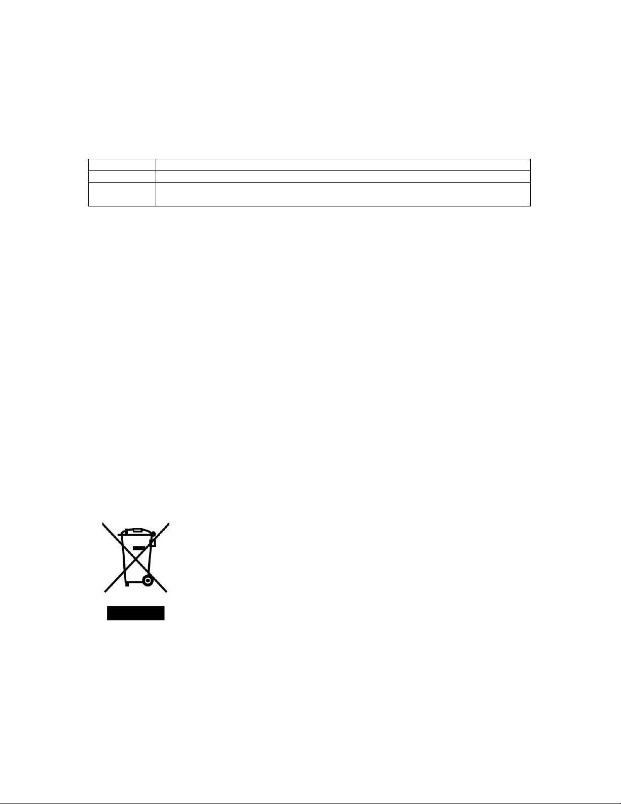
Waste Electrical and Electronic Equipment (WEEE), Directive 2002/96/EC (This directive is only valid in
the EU.)
This product complies with the WEEE Directive (2002/96/EC) marking requirement.
The following marking indicates that you must not discard this electrical/electronic product in domestic
household waste.
Product Category
With reference to the equipment types in the WEEE directive Annex 1, this product is classified as a “IT and
telecommunications equipment” product.
Do not dispose in domestic household waste.
When disposing products in the EU, contact your local distributor.
Negligence of the precautions may result in severe damage to the device or major physical
property.
Danger
Immersion
“Do not immerse the battery with liquid such as water, sea water or soda.”
If the protection circuit in the battery is broken with liquid, the battery cannot be protected and may on fire,
smoke, explode, or cause heat generation by unexpected electrical load.
LNL-1 manual Fujtecom., Inc. 2014
6
Page 7

High Temperature
“Do not use or place the battery near fire, a heater or a high temperatures (more than 80℃).”
The battery’s polyolefin separator may get damaged from the heat and could cause an internal short circuit.
This may cause the battery to catch on fire, smoke, explode, or cause heat generation.
Charger and Charge Condition
“Do not use unauthorized chargers.”
If the battery is charged under unacceptable conditions (For example: usage in restricted temperature ranges,
over voltage, or over current with unauthorized chargers) the battery may catch on fire, smoke, explode, or
cause heat generation.
Reverse Polarity
“Do not force a reverse-charge or a reverse-connection.”
The battery has correct polarity. If the battery doesn’t fit, please check the battery’s orientation and do not
force into the battery mount. If the battery is forced to set with a different polarity, the battery may catch on
fire, smoke, explode, or cause heat generation.
Direct Connection
“Do not connect the battery with AC plug (outlet) or car plugs.”
The battery requires a specific charger. If the battery connects with the outlet directly, the battery may catch
on fire, smoke, explode, or cause heat generation.
Inappropriate Use with Other Equipment
“Do not adapt the battery to unspecified applications.”
If the battery is used for unspecified applications or systems, the battery may get damaged or catch on fire,
smoke, explode, or cause heat generation.
Incineration and Heat
“Please keep the battery away from heat and fire”
The battery materials will get damaged and may catch on fire, smoke, explode, or cause heat generation.
Short-Circuit
“Do not make a short-circuit.”
Do not connect the + and - terminals with conductive material. Do not carry or store the battery with
metal objects (such as wire, necklace or hairpins). If the battery is in a short-circuit, excessive large current
will flow and may catch on fire, smoke, explode, or cause heat generation.
Impact
“Avoid unnecessary impact to the battery.”
Unnecessary impact may cause the battery to leak, heat generation, smoke fire or explode. Also, the
protection circuit may break and that will lose the function of the battery’s protection system.
Penetration
“Do not penetrate with a nail or strike with a hammer.”
The battery cell may get destroyed or damaged. And the battery’s protection circuit may get damaged and
cause an internal short-circuit. Additionally, the battery may catch on fire, smoke, explode, or cause heat
generation.
Soldering
“Do not directly solder the battery.”
The insulator could melt or the gas release vent might get damaged from the heat. Additionally, the battery
may catch on fire, smoke, explode, or cause heat generation.
Disassemble and Reconstruction
“Do not disassemble the battery.”
If the protection circuit gets damaged, the battery will not be protected. Then, the battery may catch on fire,
smoke, explode, or cause heat generation.
LNL-1 manual Fujtecom., Inc. 2014
7
Page 8

Charge near High Temperatures
“Do not charge the battery near high temperatures”
If the battery is charged near high temperatures, the battery may not be able to charge due to the activation of
the protection circuit. In these conditions, the protection circuit may break and the battery may catch on fire,
smoke, explode, or cause heat generation.
Warning
Ingestion
“Keep away from infants”
The battery should be kept away from infants. In case of swallowing the battery, see a doctor immediately.
Storing
“Do not put the battery in the microwave or other cooking appliances”
The battery may on fire, smoke, explode, or cause heat generation due to heat or the electrical impact from the
microwave.
Mixed Use
“Do not mix the battery with other batteries.”
The battery should not be used with other batteries with different capacity, chemistry or manufacturer. Do not
connect with other batteries or mix with other batteries. The battery may catch on fire, smoke, explode, or
cause heat generation.
Rust, Changing Color and Deformities
“Do not use abnormal batteries.”
Please stop using the battery if there are noticeable abnormalities such as abnormal smell, heat, deformities, or
discoloration. The battery may have a defect and may catch fire, smoke, heat generation or explode if used
continuously.
Charging Time
“Stop charging if the charging process cannot be finished.”
If the battery can not finish the charging process within the specified time, please stop the charging process.
The battery may catch on fire, smoke, explode, or cause heat generation.
Leakage ①
“Do not use a leaking battery near flames”
If the battery or liquid leaking from the battery has a pungent odor, the battery should keep away from flames.
The battery may ignite and explode.
Leakage②
“Do not touch a leaking battery”
If the liquid leaking from the battery gets into eyes, it will cause significant damage. If the leaking liquid
gets into your eyes, please flush eyes immediately with pure water. Please consult a physician immediately.
If the liquid remains in the eyes it will cause significant damage.
Transport
“Pack the battery tightly during transport”
To prevent short-circuit or damages, please tightly pack the battery into a case or a carton box.
Caution
Use under Direct Sunlight
“Do not use or leave the battery in excessive heat such as in a car in direct sunlight.
The battery may catch on fire, smoke, explode, or cause heat generation. Also, it might cause a deterioration
of battery’s characteristics and battery life.
Static Electricity
The battery pack has a protection circuit. Do not use the battery where it generates static electricity (more
then 100V) that might damage the protection circuit. If the protection circuit is broken, the battery may catch
LNL-1 manual Fujtecom., Inc. 2014
8
Page 9

on fire, smoke, explode, or cause heat generation.
Charging Temperature Range
Charging temperature range is regulated between 0℃ and 40℃. Do not charge the battery out of the
specified temperature range. Otherwise, it may cause heat generation, leakage, or a serious damage. Also, it
might cause deterioration of the battery’s characteristics and battery life.
Manual
Please read the manual before usage. Please save the manual for future reference.
Charging Method
Please read the charger’s manual for the charging method.
First Time Use
Please contact the supplier if the battery has unusual odor, heat generation or rusts during the first usage.
Use by Children
Parents must explain how to use the system and the battery. Please check back periodically to ensure children
are using the system and the battery correctly.
Inflammable Materials
Please keep away from flammable materials during the charge and the discharge. It may catch on fire, smoke,
explode, or cause heat generation.
Leakage
If electrolyte leak from the battery and adhere to the skin or clothes, immediately flush it with water.
Otherwise, it may cause skin irritation.
Insulation
If lead wires or metal objects come out from the battery, please seal and insulate them completely. Otherwise,
the battery may cause a short circuit and catch on fire, smoke, explode, or cause heat generation.
Recycle
Please recycle the battery according to local rules or regulations after use.
Warranty period
The warranty period of this product is one year (12 months) counted from the date of its purchase.
The “Warranty certificate” assures our best service to the customer. Enter the customer’s name, address and
date of purchase in the “Warranty certificate” and store safely. Kindly give the “Warranty certificate (for file)”
to our sales representative or mail it to our office. Should any functional trouble arise to this product during the
warranty period, we will carry out our repair at no cost to the customer. Presentation of the “Warranty
certificate” is required in such a case. Please kindly understand it in advance that our service will be provided
for value, unless the “Warranty certificate” is presented. If any trouble arises after the warranty period or if any
failure occurs due to a reason for which the customer is responsible, our service will be provided for value.
Please contact the nearest distributor if you have any questions regarding this product.
LNL-1 manual Fujtecom., Inc. 2014
9
Page 10

Hardware Volume
10
LNL-1 manual Fujtecom., Inc. 2014
Page 11
1. Product configuration
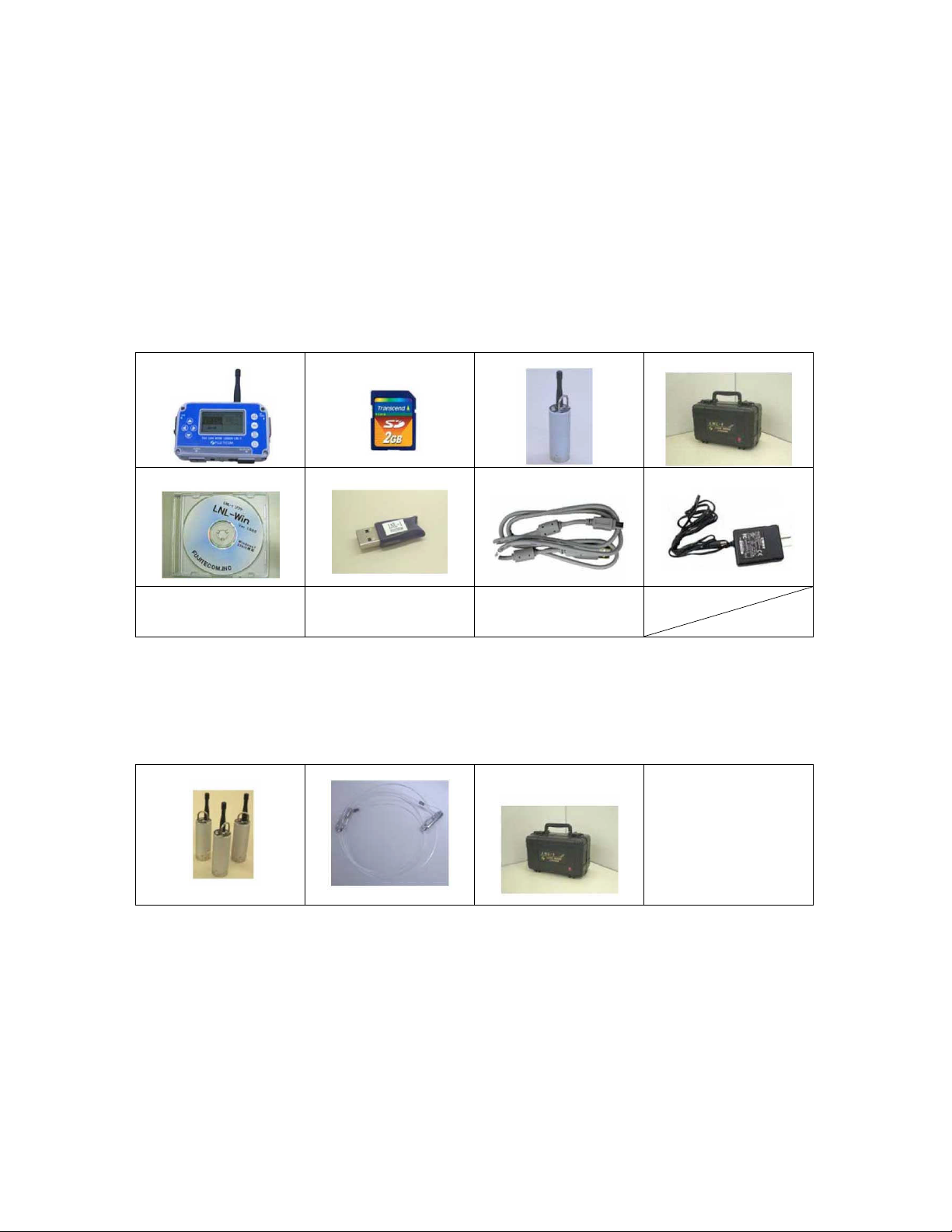
1-1 Standard products
[1] Analyzer 1
[2] SD card (2GB) 1
[3] Logger 10
[4] Storage case 1
[5] Management software 1
[6] USB authentication key 1
[7] USB cable 1
[8] AC power supply adapter (12V) 1
[9] Operation manual 1
[10] Warranty certificate 1
[1] Analyzer [2] SD card (2GB) [3] Logger [4] Storage case
[5] Management software [6] USB authentication key [7] USB cable [8] AC power supply adapter
[9] Operation manual [10] Warranty certificate
No printing
1-2 Optional accessories
[12] Additional loggers for expansional deployment (10 loggers/order)
[13] Installation rope (Jigs for installation in deep end of water)
[14] Storage case for additional loggers (Maximum 20 loggers can be contained.)
[12] Additional loggers [13] Installation rope [14] Storage box for additional
loggers
11
LNL-1 manual Fujtecom., Inc. 2014
Page 12
2. Name of each part and explanation of switches
2-1 Analyzer
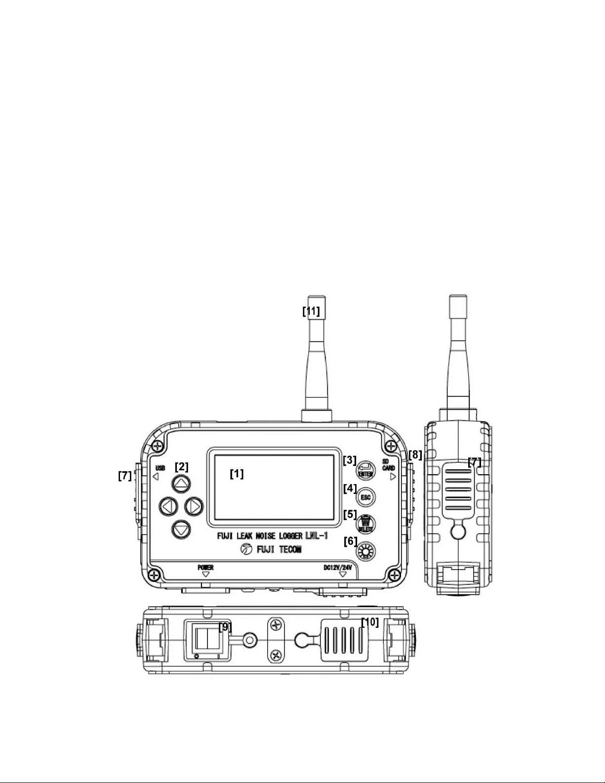
Display
[1] Liquid crystal display
[2] Arrow key This key is used when selection is made, page is moved and figures are
changed.
[3] ENTER key This key is used to fix setting.
[4] ESC key This key is used when returning to the previous screen.
[5] DELETE key This key is used for deletion of characters/words or for other operation.
[6] Backlight key Turns on/off the backlight.
Connectors and others
[7] USB USB cable is inserted into this connector when communication is made with
PC.
[8] SD CARD SD card is inserted into this connector.
[9] POWER SWITCH This switch turns on/off power supply.
[10] 12V/24VDC This terminal is used for battery charge or connection to external power
supply.
[11] Antenna This antenna receives data and transmits setting.
12
LNL-1 manual Fujtecom., Inc. 2014
Page 13
2-2 Logger
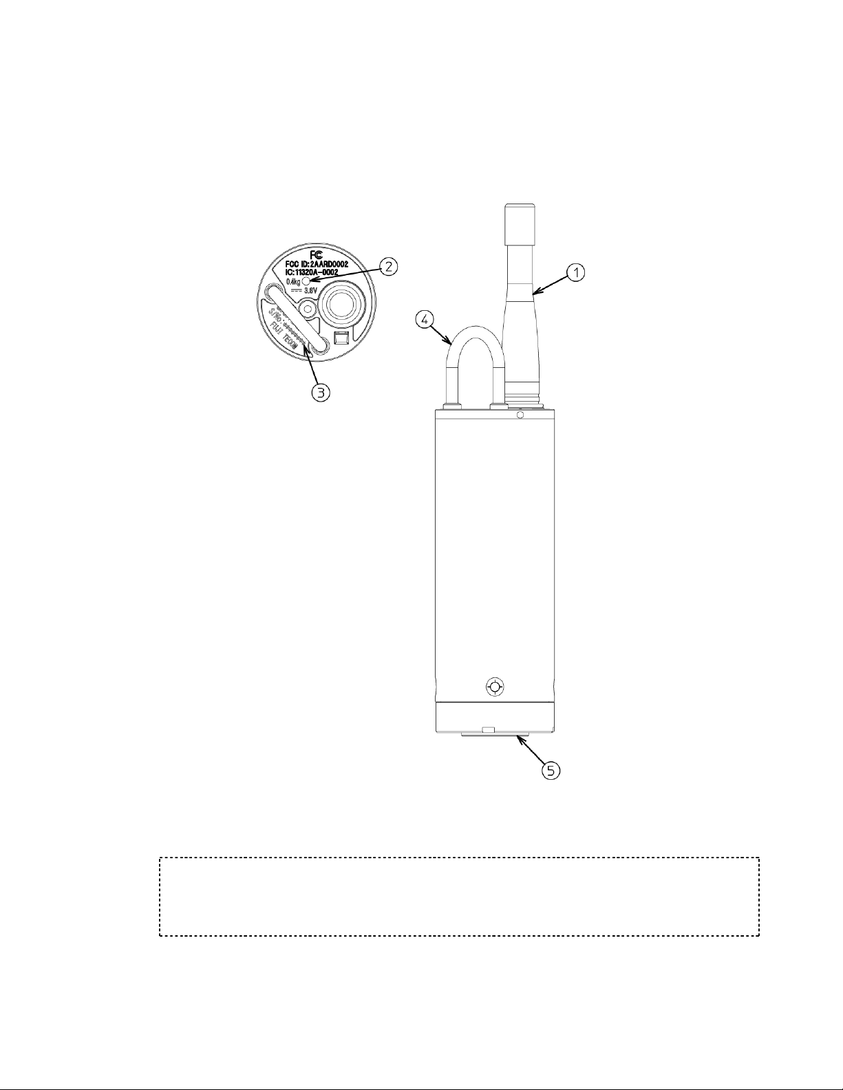
[1] Antenna This antenna is used for transmission and receiving.
[2] LED lamp Displays ON/OFF of power supply and logger status.
[3] Serial number label Serial number of loggers is indicated.
[4] Handle This handle is used to attach the installation rope for installation of the logger.
[5] Mounting section Since magnet is mounted on the tip, the logger can be installed on the valves,
etc.
When the logger is taken out from its storage case, the logger power supply is turned on. While the
logger is kept in its storage case, its power supply is turned off.
Although the logger emits clattery sound when it is strongly swung up and down, there is no problem
with the product quality.
Caution
Never remove the antennas from the analyzer and logger. If removed, failure may result.
Use the provided USB cable to connect the analyzer to a PC. If other USB cables than the provided USB
cable are used, failure may result.
LNL-1 manual Fujtecom., Inc. 2014
13
Page 14
3. Before use of the product
Check of received products
Ensure that you have received all the products shown in the Product Configuration (See Page 11).
Check of SD card insertion
Ensure that the SD card is inserted into the analyzer.
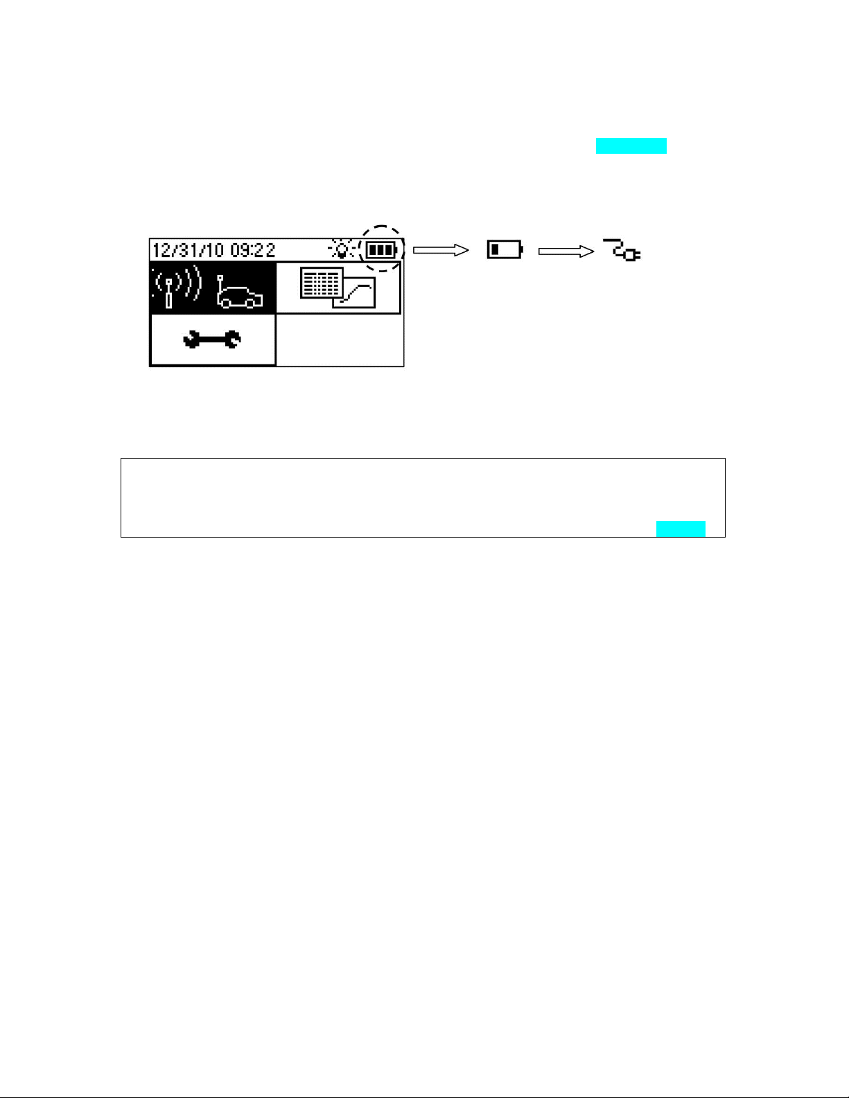
Check of analyzer battery capacity (charging)
Turn on the power supply of the analyzer and check the battery capacity.
The battery is not
charged.
If the battery is not charged, connect the AC power supply adapter to the analyzer via power supply connector in
order to charge the battery. When the AC power supply adapter is connected, the battery icon changes to the
outlet icon. The outlet icon “blinks” while the battery is being charged and stays “lit” when charging is
completed.
Caution
Charging time
Battery charge is completed within about 3.5 hours (from the status where the battery is completely dead).
Be sure to charge the battery indoors (0 to 40C).
If ambient temperature is very high, battery charge may not be performed (See Section 10-3 on Page 34.)
Check of analyzer date and time (setting)
Check the date and time set on the analyzer. If not correct, correct them (See Page 25).
Initial setting (logger registration to analyzer) (See Page 20.)
Check of device operation (test mode) (See Page 31.)
The battery is being
charged.
14
LNL-1 manual Fujtecom., Inc. 2014
Page 15
4. Work flow
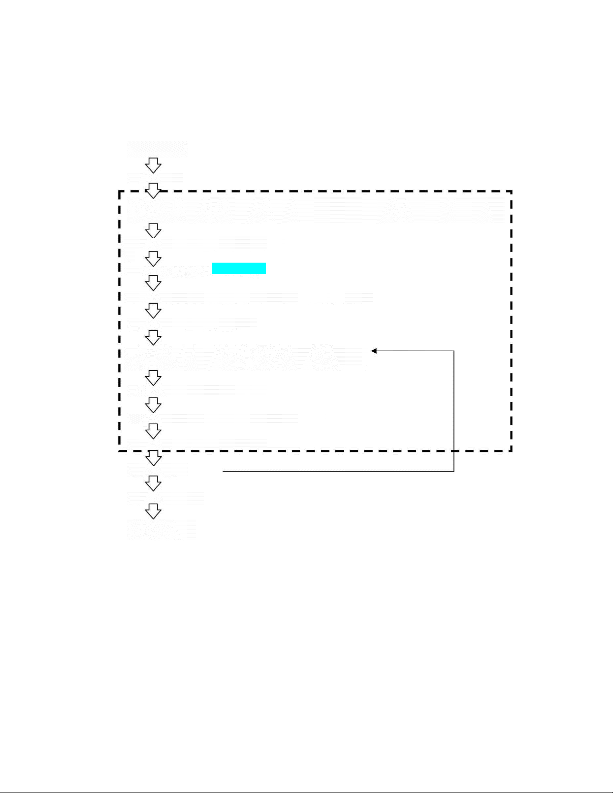
For use of Leak Nets, the actual workflow is shown below. See the relevant section for operation necessary for
each work.
4-1 Monitoring of pipeline
Work plan
Preliminary inspection of field site
Initial setting
(Initial registration of logger, ID setting (arbitrary setting)) Recommended to perform only for initial setting or
immediately after formatting the card.
Check of device operation in the test mode (See Page 31.)
Setting of logger (See Page 23 to 28.)
Loggers to be set are registered on the data collection screen. (Arbitrary)
Setting the loggers on the monitoring spots
Collection appointment on thedata collection screen (Arbitrary)
(See Page 20.)
* This can be performed only for the loggers the IDs of which are displayed on the collection screen.
Data collection (See Page 20.)
Transfer of data from analyzer to PC (See Page 33.)
Analysis by PC (See Page 103 to 114.)
Selection of pipeline
Confirmation survey
Making of report
15
LNL-1 manual Fujtecom., Inc. 2014
Page 16
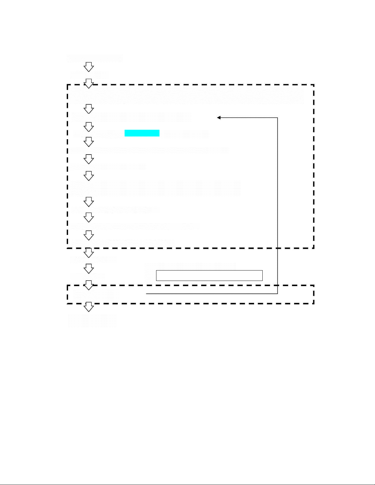
4-2 Selection of pipeline
Work plan
Preliminary inspection of field site
Initial setting
(Initial registration of logger, ID setting (arbitrary setting)) Recommended to perform only for initial setting or
immediately after formatting the card.
Check of device operation in the test mode (See Page 31.)
Setting of logger (See Page 23 to 28.)
Loggers to be set are registered on the data collection screen. (Arbitrary)
Setting the loggers on the monitoring spots
Collection appointment on the data collection screen (Arbitrary) (See Page 20.)
This can be performed only for the loggers the IDs of which are displayed on the collection screen.
Data collection (See Page 20.)
Transfer of data from analyzer to PC (See Page 33.)
Analysis by PC (See Page 103 to 114.)
Selection of pipeline
Confirmation survey
Moving to other investigation area
Removal of loggers
Making of report
16
LNL-1 manual Fujtecom., Inc. 2014
Page 17

5. Setting of device and operating procedure
Initial setting
Setting of time on analyzer (See Page 25.)
Registration of loggers to analyzer and logger ID setting (arbitrary setting)
Installation of management software into PC and installation of driver
(See the Software Section from Page 41 onwards.)
[1] “Setting of logger conditions” by analyzer
Measurement time
Measurement interval
Threshold value
Conditions for data collection
Transmission of setting conditions to logger
[2] “Installation” of loggers on field site
Installing the loggers on the fire hydrants, valves, etc. in the monitoring/selection area.
[3] “Data record”
Recording data according to the recording condition set on the loggers.
[4] “Collection of data”
Data are collected at the specified time on the specified day of the week according to the data collecting
conditions set in the logger setting.
Data are collected via wireless communication.
[5] “Transfer of data to PC”
Data transfer via USB cable connection
Data transfer via SD card
[6] “Analysis” by management software
Data are loaded into the management software and saved.
Data are displayed in list and various graphs, printed out and output in EXCEL.
(See the Software Section from Page 41 onwards.)
17
LNL-1 manual Fujtecom., Inc. 2014
Page 18
6. Display and function of logger
6-1 Turning on the power supply
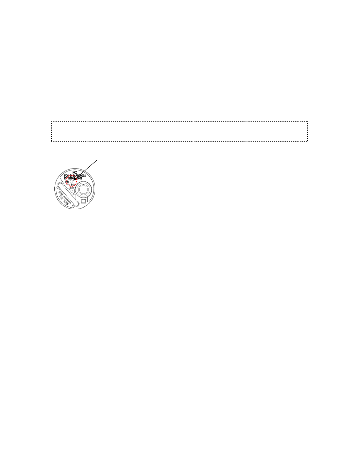
The logger power supply is turned OFF while it is contained in its storage case. When the logger is taken out
from its storage case, the LED “blinks five times” and the power supply is turned ON. When the power
supply is turned ON, the logger transmits radio signals.
6-2 Turning off the power supply
When the magnet is neared, the LED is “lit”, then it turns off two seconds later and the power supply is
turned OFF. When the logger is put into its storage case, the same operation is performed.
* When the magnet is kept away, the logger power supply is turned ON.
Note:
If the logger LED “blinks at one-second interval” after “lighting for five seconds”, it may be faulty. Contact your
sales representative for repair.
LED lamp
18
LNL-1 manual Fujtecom., Inc. 2014
Page 19
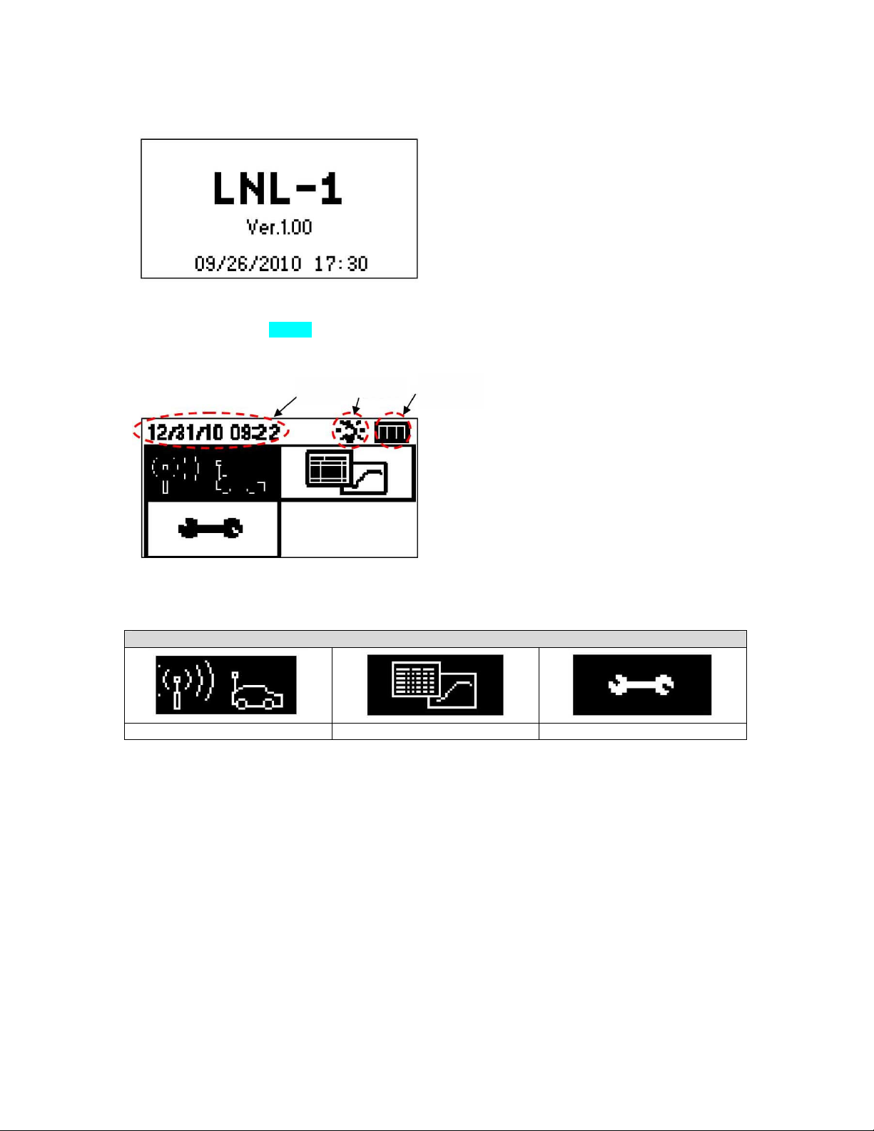
7. Analyzer display screen and function
7-1 “Start screen”
When the power supply is turned on, the model, version, date and time are displayed.
If the date and time are not correct, display the “Date/Time Setting Screen” from the setting menu and
correct them (See Page 23).
7-2 “Main menu”
Date/time Backlight
Remaining battery capacity
Three icons for “Logger Data Collection Menu”, “Data Display Menu” and “Setting Menu” are displayed in
the main menu. Select one of them with the arrow keys and press the ENTER key to move to the respective
menus.
Main menu
“Logger Data Collection Menu” “Data Display Menu” “Setting Menu”
19
LNL-1 manual Fujtecom., Inc. 2014
Page 20
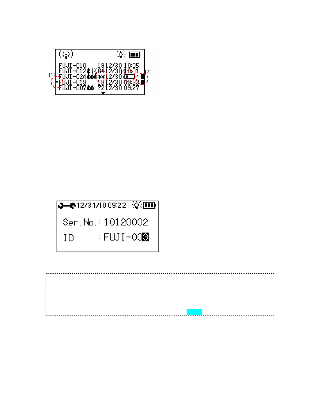
7-3 “Logger Data Collection Menu”
[1] “” on the left is the “new logger mark”, which is
indicated for the new logger recognized for the first
time.
[2] “”on the right is the “Automatic Collection
Mark”, which is indicated when collection is
appointed. The ENTER key is used to appoint
collection and release appointment for each logger.
The DELETE key is used to perform batch selection
and release (deselect).
When the logger is detected, a beep sound is emitted once.
When data is received from the logger in the waiting status, the latest data is displayed on the top. Data
received from the logger (logger ID, judgment result, minimum sound level, and date & time of receipt) are
displayed. Maximum 500 logger data are displayed and the right/left arrow keys are used to display the
loggers on the previous/next pages.
[3]“**” is displayed when the complete logger data cannot be obtained due to communication error, etc.
If “**” is displayed, the automatic collection mark is attached/displayed and the logger data is re-obtained.
[4] When the battery requires a replacement, the battery mark and the time are displayed alternately in the
time display section. Stop use of the relevant logger promptly and replace it with new one or replace the
battery.
When unregistered logger is detected
If a logger not registered in the analyzer is detected, a beep is emitted once, a blip is emitted three times, and
“Unregistered Logger Handling Screen” is displayed.
Registration of logger ID is performed (or only serial number is used). Use the up/down/right/left arrow keys to
change the ID and press the ENTER key to execute registration.
Caution
The ID already used cannot be registered.
If the new ID returns to the old one when the ENTER key is pressed, such new ID is the already used logger
ID.
Register a different logger ID.
If multiple loggers are detected newly, the logger detected last is displayed.
For edit of logger ID, see the “Logger ID Display Edit Screen” on Page 20.
LNL-1 manual Fujtecom., Inc. 2014
20
Page 21
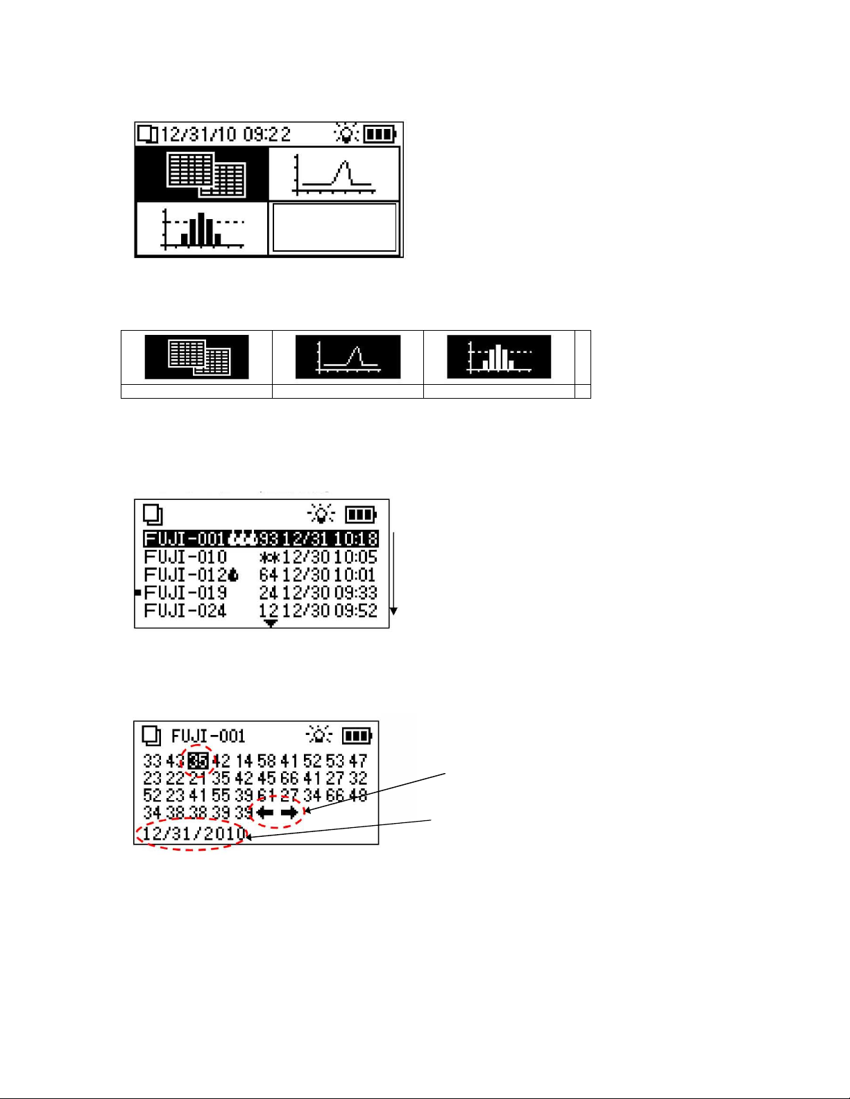
7-4 “Data Display Menu”
In the data display menu, use the arrow keys to select a data display form and press the ENTER key to
execute the selection.
There are the following 3 data display forms.
“Min. sound level list display” “Trend graph display” “Histogram display”
When each display form is selected and executed, the “Logger List Display Screen” is displayed. Use the
up/down arrows to select and display the intended logger.
7-4-1 “Logger List Display Screen”
In this screen, reordering of loggers can be performed.
Logger ID order:
Ascending order/Descending order
Min. sound level order
Descending order/Ascending order
Collection date order
Descending order/Ascending order
In the status where the inverse cursor is located at the
top, press the up arrow key to reorder the loggers.
Use the up/down arrow keys to highlight the intended logger and press the ENTER key to execute the selection.
The values or graph is displayed.
7-4-2 “Min. sound level list display screen”
In this screen, move the cursor to the right/left arrow
character and press the ENTER key to display and see
the intended logger one by one.
Right arrow: to the next logger
Left arrow: to the previous logger
The date when the highlighted minimum sound level
was recorded is displayed.
The minimum sound level (dB) of each day for logger selected in the “Logger List Display Screen” is displayed.
The minimum sound levels for 35 days are displayed. (If the display is blank, no measurement data is available.)
LNL-1 manual Fujtecom., Inc. 2014
21
Page 22
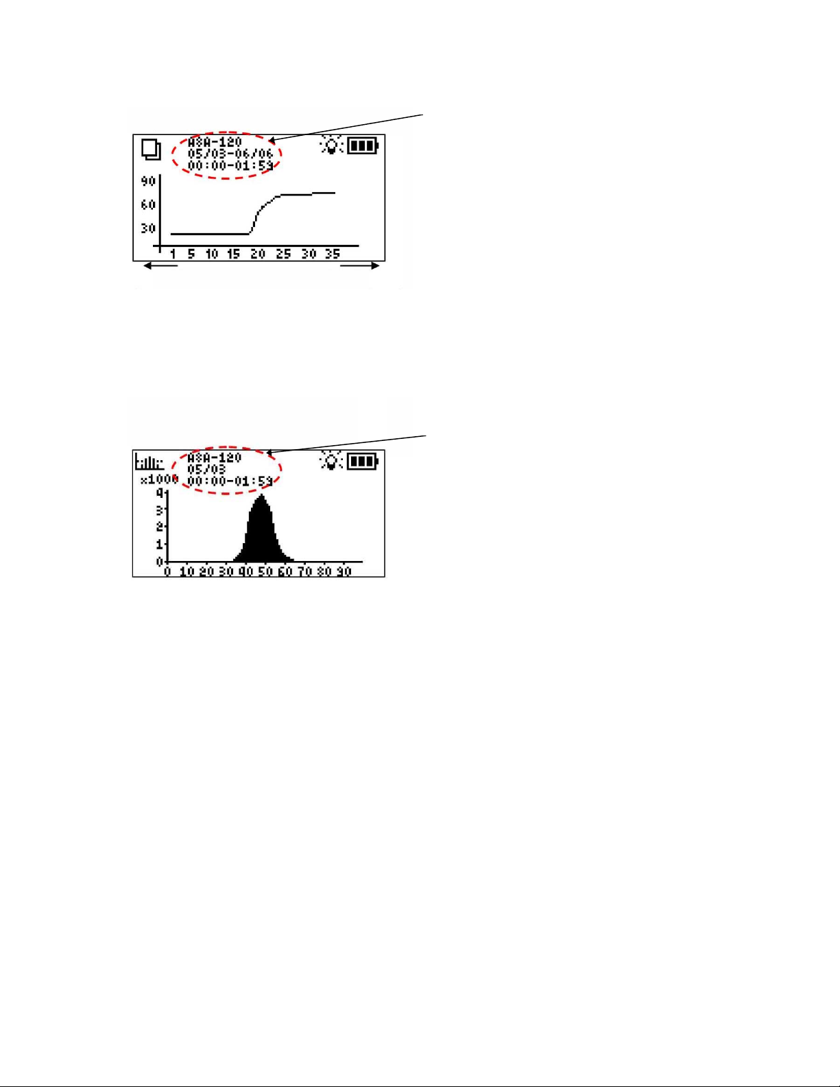
7-4-3 “Trend Graph Display”
Latest
Logger ID
Data collection period
Time of recording
In this screen, use the right/left arrow keys to display
and see the intended loggers one by one.
Right arrow key: to the next logger
Left arrow key: to the previous logger
35 days ago
This screen displays the trend graph of the minimum sound levels for the logger selected in the “Logger List
Display Screen”. The vertical axis indicates the sound level (dB) and the horizontal axis indicates the data
recording day.
(The vertical axis is adjusted automatically.)
7-4-4 “Histogram Display Screen”
Logger ID
Measurement date
Time of recording
In this screen, use the right/left arrow keys to display
and see the intended loggers one by one.
Right arrow key: to the next logger
Left arrow key: to the previous logger
Use the up/down arrow keys to change the displayed
logger date.
Up arrow key: to the graph of the next day
Down arrow key: to the graph of the previous day
This screen displays the histogram for the logger selected in the “Logger List Display Screen”. The vertical axis
indicates the number of samples, and the horizontal axis indicates the sound levels (dB).
(The vertical axis is adjusted automatically.)
.
LNL-1 manual Fujtecom., Inc. 2014
22
Page 23
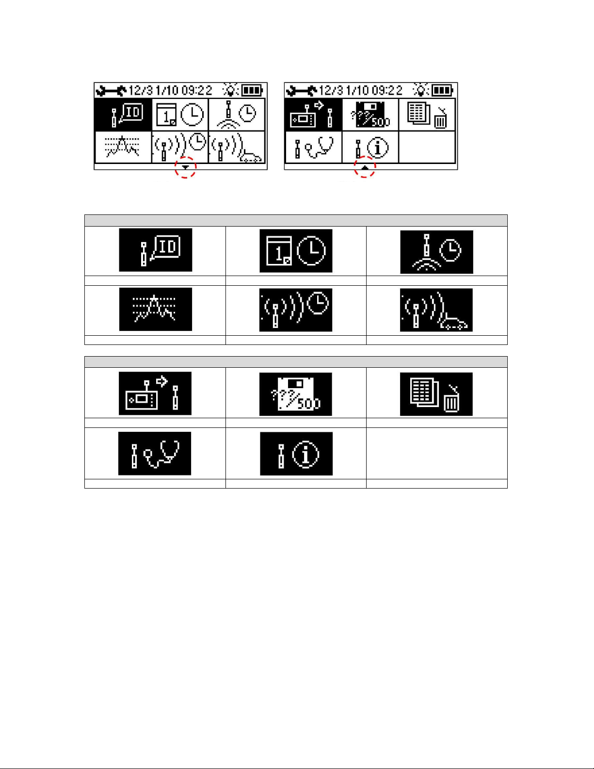
7-5 “Setting Menu”
Setting Menu 1 Setting Menu 2
In the setting menu, the following 11 selections are available.
Setting Menu 1
“Logger ID edit” “Date and time setting” “Recording time setting”
“Threshold value setting” “Data collection time setting” “Data collection day-of-week setting”
Setting Menu 2
“Logger setting” “Check of analyzer memory capacity” “Delete of logger data”
“Logger test mode” “Check of logger setting”
In the setting menus 1 and 2, use the up/down/right/left arrow keys to change screen.
23
LNL-1 manual Fujtecom., Inc. 2014
Page 24
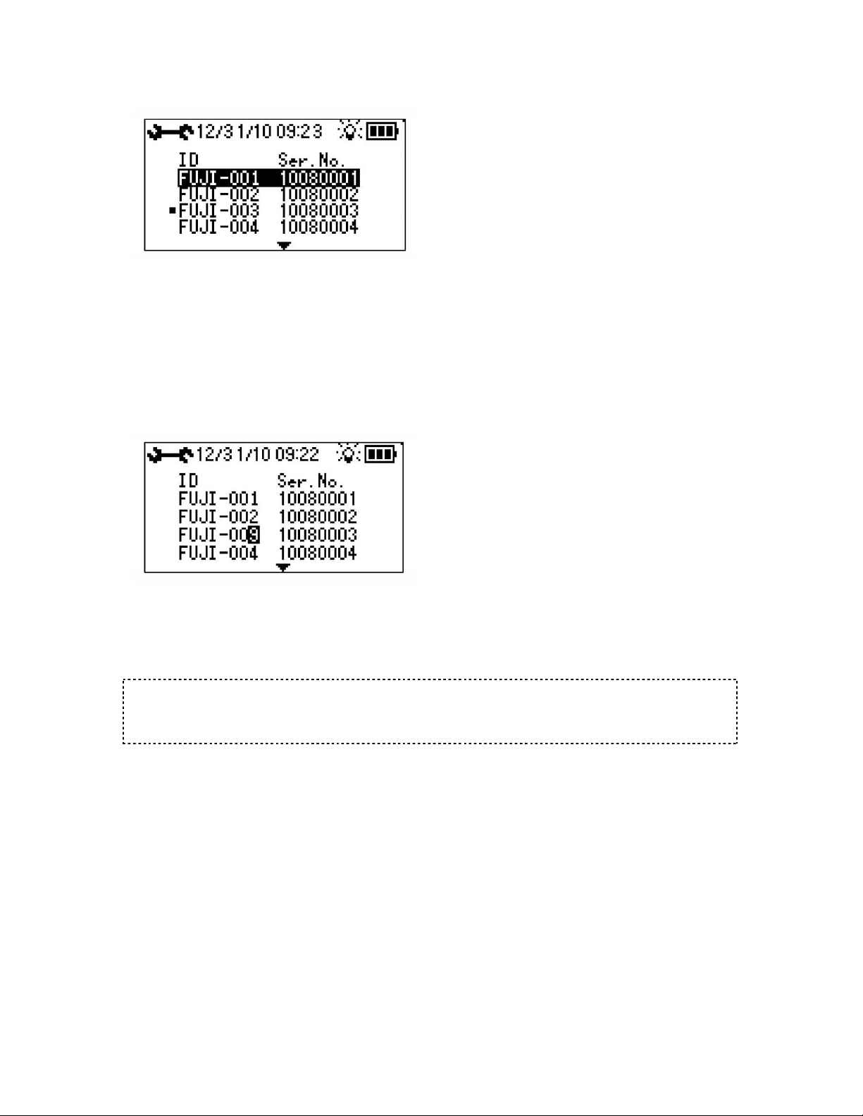
7-5-1 “Logger ID Editing Screen (Logger Selection)”
ID other than the serial number can be prepared for identification of each logger. For example, the installed valve
number or the field site number can be used for easier identification of the installed logger.
In the initial setting, the logger ID is the same as the serial number.
If the DELETE key is pressed in the invert selection status, the selected logger can be deleted from the SD
card.
When the logger for which you wish to perform ID edit is highlighted with the up/down/right/left keys and the
selection is executed with the ENTER key, the screen changes to the “ID Edit”.
7-5-2 “Logger ID Editing Screen (ID Edit)”
The logger ID corresponding to the serial number can be edited. Highlight the section you wish to change with
the up/down arrow keys and enter the number/alphabetic letter/code. Use the DEL key to delete letters. The
ENTER key is used to confirm the change and the ESC key is used to cancel the change. (The ID within logger
is not changed at this moment. It is changed when communication with the logger is completed next time.
Maximum eight letters can be entered.)
Caution
If the new logger ID returns to the old one, such new logger ID is already used. The same logger ID cannot
be registered twice.
Be careful because if the ID is changed, the logger data of the relevant serial number is deleted.
24
LNL-1 manual Fujtecom., Inc. 2014
Page 25
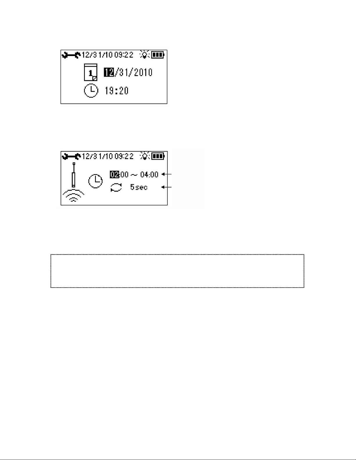
7-5-3 “Date/time Setting Screen”
This screen is used for setting the date/time of the analyzer main body. Use the up/down arrow keys to change
the year/month/day/time.
Use the right/left keys to move to other setting items and press the ENTER key to save the setting.
7-5-4 “Measurement Time Setting Screen”
Measurement time
Measurement interval
This screen is used to set the logger measurement starting time and the measurement interval. (Measurement
time: 2 hours, measurement interval: 1 to 60 seconds, and maximum sampling numbers: 7200 data/day)
Use the up/down arrow keys to change the measurement starting time and the measurement interval.
Use the right/left keys to move to other setting items and press the ENTER key to save the setting.
When the measurement starting time is decided, the measurement ending time is automatically set to be two
hours later.
Caution
If sufficient collection time is not kept, the measurement time returns to the previous measurement time
when the ENTER key is pressed to save the setting. Be careful so that the measurement time and the
collection time do not overlap each other. If the measurement time and the collection time must overlap each
other, set the collection time to be 4 hours or more.
25
LNL-1 manual Fujtecom., Inc. 2014
Page 26
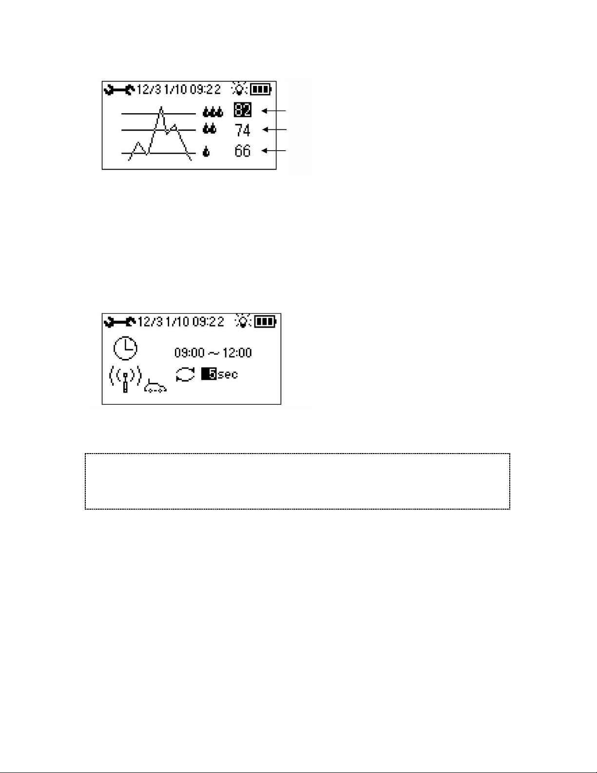
7-5-5 “Threshold Value Setting Screen”
LV 3
LV 2
LV 1
This screen is used to set the threshold in three levels to judge the abnormal sound level. Use the up/down arrow
keys to change the threshold value. Use the right /left keys to move to other setting item and press the ENTER
key to save the setting. When a recorded sound level exceeds the preset threshold, the sound level is judged to be
abnormal and the water-drop mark is displayed.
(Initial setting of threshold value)
The initial setting of the threshold value is made as follows: LV1: 40, LV2: 55 and LV3: 65.
Setting needs to be performed in each field site according to the environment of the area selected and the sound
intensity. Contact our sales people for details.
7-5-6 “Data Collection Time Setting Screen”
This screen is used to set the data collection time period and the transmission interval of logger.
Use the up/down arrow keys to change the data collection starting/ending times and the transmission interval.
Use the right/left keys to move to other setting items and press the ENTER key to save the setting.
Caution
If sufficient data collection time is not kept, the measurement time returns to the previous measurement time
when the ENTER key is pressed to save the setting. Be careful so that the measurement time and the data
collection time do not overlap each other. If the measurement time and the data collection time must overlap
each other, set the data collection time to be 4 hours or more.
26
LNL-1 manual Fujtecom., Inc. 2014
Page 27
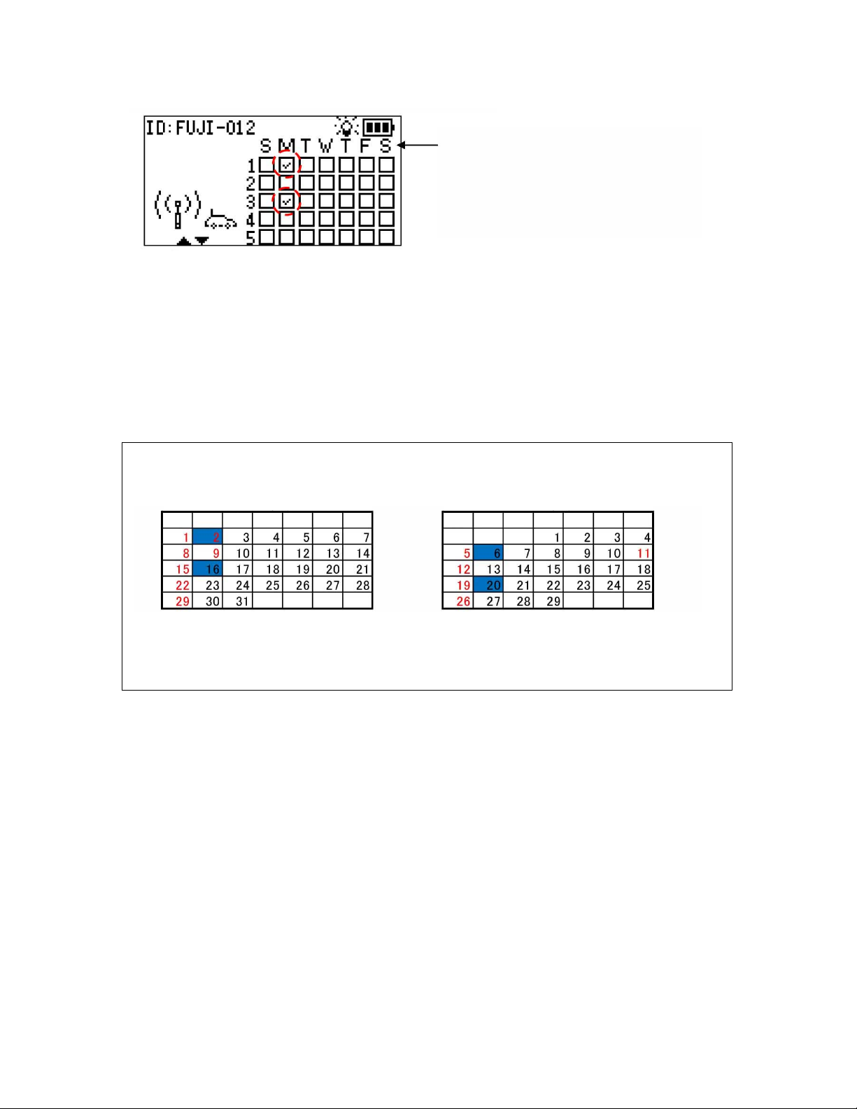
7-5-7 “Data Collection Day-of-week Setting Screen”
SuMoTuWeThFrSaSuMo
Tu
WeThFr
Sa
Day of week
(S: Sunday, M: Monday, T: Tuesday, W: Wednesday,
T: Thursday, F: Friday, and S: Saturday in that order)
Day of the week for data collection is set.
Use the up/down/right/left arrow keys to move the cursor.
Use the DEL key to set/release the checkmark in the cursor position. If the DEL key is pressed when the cursor
is on a day-of-week code, checkmark is set/released for all of the designated day of the week.
Press the ENTER key to save the setting.
Be sure to check mark in one day of the week for data collection.
If setting is performed as shown in the above screen, collection is performed on the first and third Mondays.
125
(Setting example) If setting is made as shown in the above screen so that collection is performed on two
Mondays, collection is actually performed as follows:
Jan. 2012 Feb. 2012
Collection is performed on Jan. 2 and 16. Collection is performed on Feb. 6 and 20.
As shown above, setting is made to decide “on which Monday of the month” collection is to be performed.
In January in the above case, collection is performed on Jan. 2 (first Monday) and Jan. 16 (third Monday).
In February, collection is performed on Feb. 6 (first Monday) and Feb. 20 (third Monday).
LNL-1 manual Fujtecom., Inc. 2014
27
Page 28
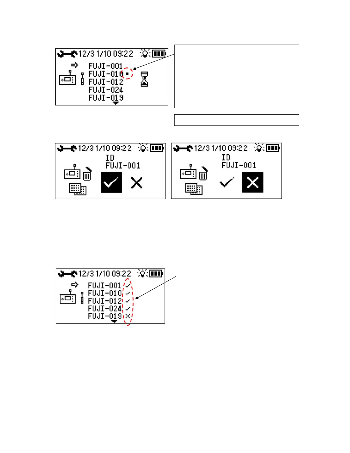
7-5-8 “Logger Setting Screen”
Delete execution icon Delete cancellation icon
Logger communication exclusion mark
This mark is set when you do not wish to overwrite the setting.
Select the logger ID and use the DELETE key to perform
setting/release.
The exclusion mark is also attached in the following cases.
* When the logger power supply is turned on/off
* This mark is set to detect the logger in the collection time period.
* Automatically attached in the communication time period, but not
attached immediately after power supply is turned on
* 10 minutes before logging
* Automatically attached also during logging time
If the DELETE key is pressed in the invert selection (highlighted)
status, the selected logger can be deleted from the SD card.
Use the right/left arrow keys to select the icon.
When the delete execution icon is selected and the ENTER key is pressed, delete is executed.
The loggers that can be connected via wireless communication are searched/displayed.
The conditions set in the “Measurement Time Setting Screen”, “Threshold Value Setting Screen”, “Collection
Time Setting Screen” and “Collection Day-of-week Setting Screen” are set in the loggers. When setting of the
conditions to the loggers is finished, “Setting Transmission Result” is displayed.
Display of setting transmission result
: success, : failure
Perform resetting for the failed logger. For the logger
for which setting is failed, resetting can also be
performed by pressing the ENTER key in this screen.
28
LNL-1 manual Fujtecom., Inc. 2014
Page 29
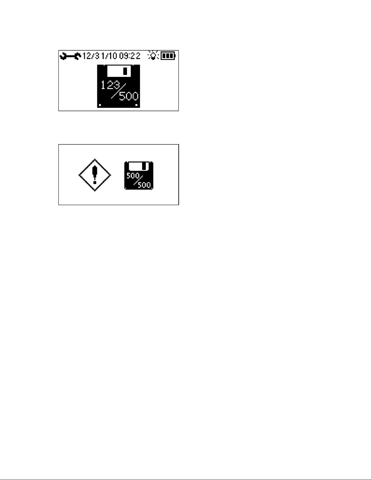
7-5-9 Analyzer Memory Capacity Check Screen”
This screen displays the number of registered loggers within the analyzer (SD card).
Maximum 500 loggers can be registered in the analyzer (SD card).
If the maximum number of loggers is registered, the “Full Memory Capacity Screen” is displayed.
No more logger can be registered.
Delete the registered logger, or use another SD card.
29
LNL-1 manual Fujtecom., Inc. 2014
Page 30
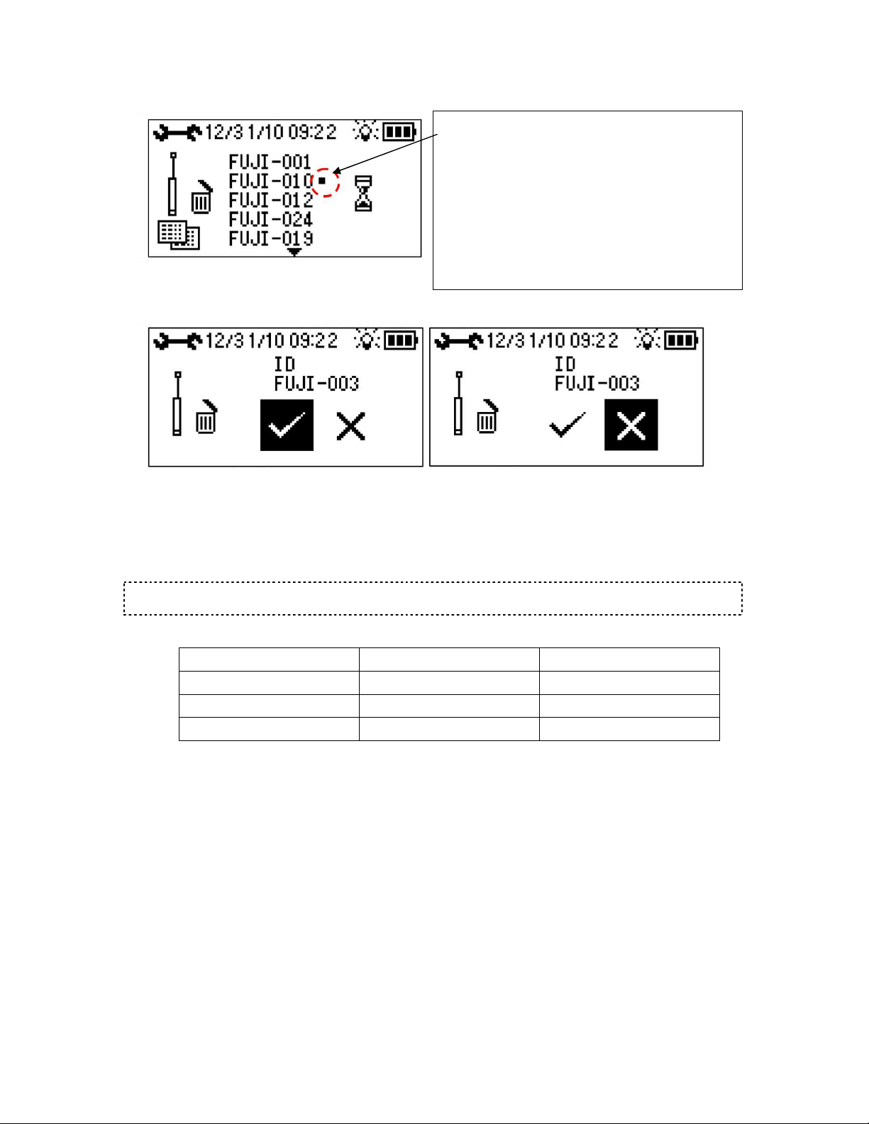
7-5-10 “Data Delete Selection Screen”
Logger communication exclusion mark
This mark is set when you do not wish to overwrite the setting.
Select the logger ID and use the DELETE key to perform
setting/release.
The exclusion mark is also attached in the following cases.
* When the logger power supply is turned on/off
* This mark is set to detect the logger in the collection time period.
* Automatically attached in the communication time period, but not
attached immediately after power supply is turned on
* 10 minutes before logging
The loggers that can be connected via wireless communication
can be searched/displayed.
* Automatically attached also during logging time
When the ENTER key is pressed, the data delete confirmation screen is displayed.
Delete execution icon Delete cancellation icon
Use the right/left arrow keys to select the icon.
When the delete execution icon is selected and the ENTER key is pressed, delete is executed.
When the delete cancel icon is selected and the ENTER key is pressed, delete is cancelled and the screen returns
to the “Data Delete Selection Screen”.
Caution
If delete is executed, the data saved in the logger and analyzer SD card are deleted.
Data clear function via analyzer (three functions)
Data within analyzer Data within logger
Logger ID editing Deleted Not deleted
Logger setting Not deleted Deleted
Data delete Deleted Deleted
30
LNL-1 manual Fujtecom., Inc. 2014
Page 31
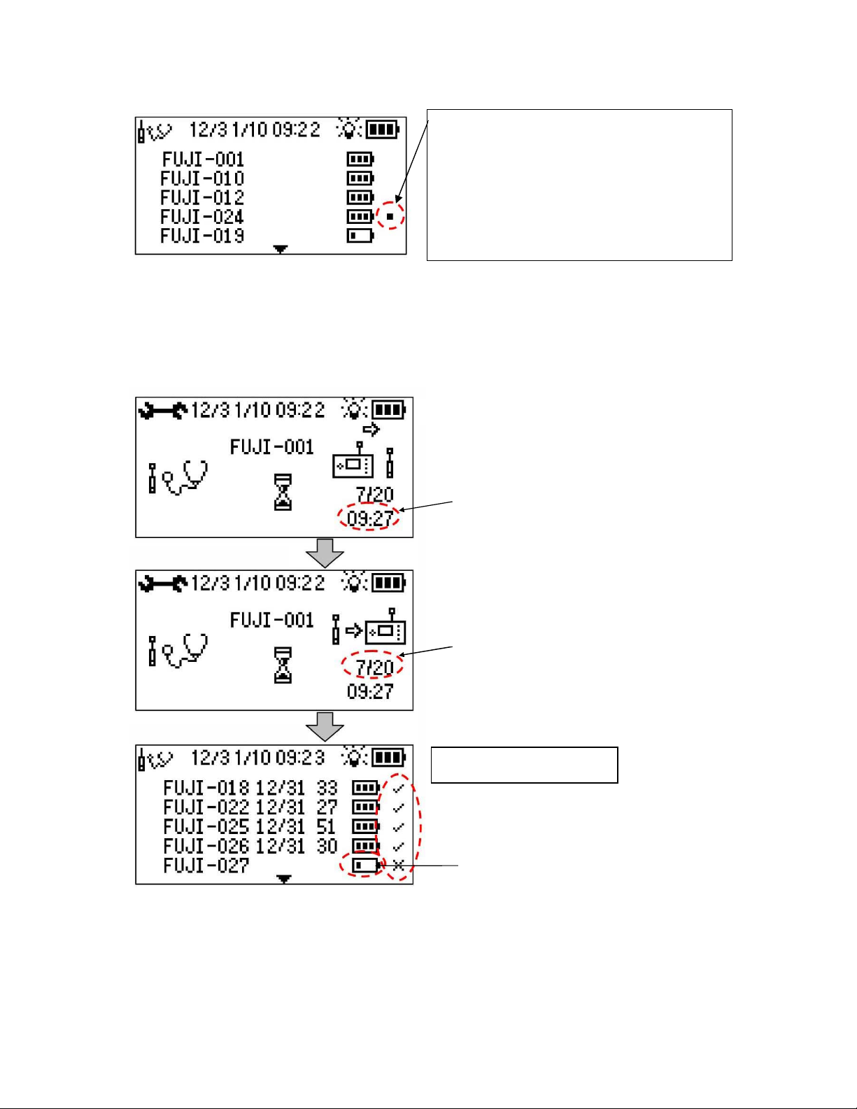
7-5-11 Logger Test Mode Screen”
Logger communication exclusion mark
This mark is set when you do not wish to overwrite the setting.
Select the logger ID and use the DELETE key to perform
setting/release.
The exclusion mark is also attached in the following cases.
* When the logger power supply is turned on/off
* This mark is set to detect the logger in the collection time period.
* Automatically attached in the communication time period, but not
attached immediately after power supply is turned on
* 10 minutes before logging
* Automatically attached also during logging time
This screen is used to test the loggers.
The loggers that can be connected are searched/displayed via wireless communication.
When the ENTER key is pressed for execution, the test is started.
The screen changes from “Test Start Command Transmission Screen” to “Test Result Waiting Screen” and
“Received Test Result Display Screen”, and the test result is displayed.
Test is conducted for 5 minutes per logger.
“Test Start Command Transmission Screen”
The expected test completion time is displayed.
“Test Result Waiting Screen”
“Received Test Result Display
Screen”
The test progress is displayed.
(The 7th of 20 loggers is being tested.)
Display of received test result
: success, : failure
The remaining battery capacity is low.
Ask for replacement of the battery.
31
LNL-1 manual Fujtecom., Inc. 2014
Page 32
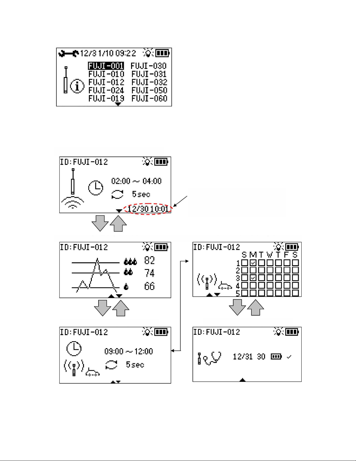
7-5-12 Logger Setting Confirmation Screen”
“
Data Collection Day
-of-
week Setting
“
Confirma
tion Screen for Data Collection
This screen is used to confirm the logger setting conditions.
When the logger ID is invert-selected (highlighted) with the arrow keys and the ENTER key is pressed to
execute the selection, the following setting conditions can be checked.
The up/down keys are used for screen transitions, and the right/left keys are used to display the previous or next
logger.
“Measurement Time Setting Confirmation Screen”
The date and time when the logger setting
conditions were obtained are displayed.
“Threshold Value Setting Screen”
Condition Setting”
“Logger Test Result Conformation Screen”
Confirmation Screen”
Since these are the “setting confirmation screens”, setting cannot be changed in these screens. Perform
change of setting in the respective setting screens.
LNL-1 manual Fujtecom., Inc. 2014
32
Page 33
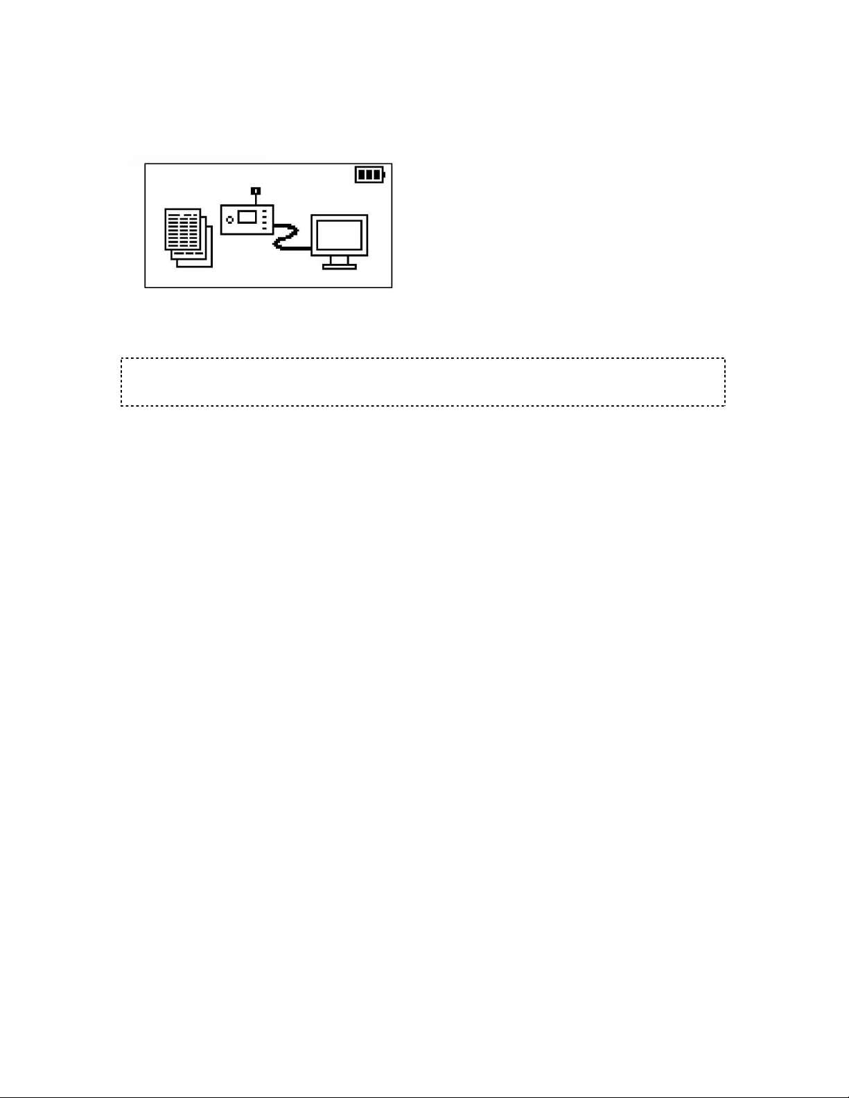
8. Data transfer to PC
8-1 Data transfer via USB cable
“PC Connection Screen”
[1] This screen is displayed when the analyzer and the PC is connected via USB cable.
[2] Data is read from the management software side.
(See Page 55 and 68 of “Software volume” for the details.)
Caution
This screen cannot be displayed when the analyzer battery mark blinks.
If the remaining battery capacity is low, charge the battery or connect the AC adapter.
8-2 Data transfer via SD card
[1] Turn off the analyzer power supply and take out the SD card from the main body.
[2] Insert the SD card into the SD card reader of the PC side.
[3] Read the data from the management software side.
(See Page 55 and 68 of “Software” for the details.)
33
LNL-1 manual Fujtecom., Inc. 2014
Page 34

9. Storage
If the equipment is not used for a long period, store it in the following procedure:
[1] Ensure that all the products including the operation manual are present.
[2] Be sure to put the loggers into their specified storage case.
[3] Store the equipment in the place not subject to moisture and dust.
<Storage after use>
[1] Remove the dirt and contaminants cleanly from the loggers.
If they are wet, wipe off the moisture.
[2] Be sure to put the loggers into their specified storage case.
(Otherwise the logger power supply is not turned off.)
[3] Cover the respective analyzer terminals with the rubber caps.
(Otherwise the terminals may be damaged or failure may result.)
[4] Put this equipment only into its storage case.
(Otherwise equipment may be damaged or failure may result.)
34
LNL-1 manual Fujtecom., Inc. 2014
Page 35
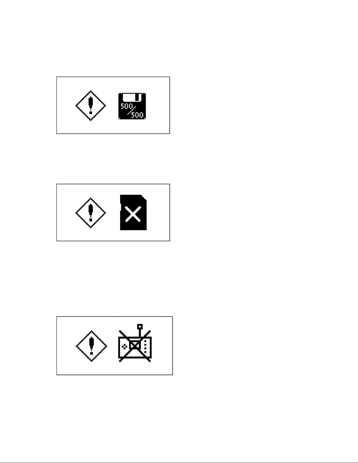
10. Message
10-1 “Full Memory Capacity Screen”
When data are registered up to the maximum quantity of 500, this screen is displayed after analyzer power
supply is turned on. The screen changes to the “Main Menu” when any key is pressed or 10 seconds later.
Delete the already registered data or use another SD card.
10-2 “Memory Card Error Screen”
If the memory card cannot be recognized or an error occurs to it, this screen is displayed when the analyzer
power supply is turned on or the memory card is accessed.
Check whether the memory card is inserted.
Pull out the memory card and reinsert it.
Format the memory card.
Use a new memory card.
10-3 “Analyzer Error Screen”
This screen is displayed if an error is detected in the analyzer when the analyzer power supply is turned on or if
its battery is charged at high temperature of 40 degrees or more. The power supply is automatically turned off
three seconds later.
Contact your sales representative for repair.
Stop charging the battery and cool the analyzer in the well-ventilated cool place.
35
LNL-1 manual Fujtecom., Inc. 2014
Page 36
11. List of initial settings
<Initial setting values of analyzer>
Setting item Initial setting value
Record starting time 02:00
Record ending time 04:00
Measurement interval 60 seconds
Threshold value (LV1) 40
Threshold value (LV2) 55
Threshold value (LV3) 65
Waiting start time 10:00
Waiting end time 13:00
Waiting interval 60 seconds
Day of week for collection First and third Tuesdays of the month
36
LNL-1 manual Fujtecom., Inc. 2014
Page 37

12. Product specifications
12-1 Analyzer
Power supply
Consumption ampere
External power supply 12VDC (12-24V DC)
Operating temperature range
Protection level IP52
Continuous operating time 10 hours or more (with backlight turned on during communication
Charging time About 3.5 hours
Display LCD
External connection terminal USB, External power supply, Charging terminal
Memory SD card (2GB)
Number of saved data 500 data (for 500 loggers)
Dimensions and weight 166 mm(W) 40 mm(D) 105 mm(H), About 560g
12-2 Logger
Power supply
Consumption ampere
Operating temperature range
Protection level IP68 (water depth 2m)
Continuous operating time
Display Power supply On/Off status displayed by LED
Memory Nonvolatile ring memory
Save data Measurement data (maximum 35 days)
Number of saved data Max. 7,200 (measurement interval 1 sec.) 35 days = 252,000
Dimensions and weight
Rechargeable lithium-ion battery
0.3A (1.1A during the charge)
-20 to 50C
at normal temperature)
(not including protrusion)
Lithium battery
0.1A
-20 to 50C
8 years or more (+20C) at our specified setting conditions
40 (D) 115 (H) mm, 400g
12-3 Radio (Common to the analyzer and logger)
Frequency 429MHz band
Channel space 12.5kHz
Modulation method GFSK
Output power 0.001mW
Transmission speed 7200bps
Output impedance
12-4 USB cable
Standards Compatible with USB2.0
Connecter Mini B-A type
Cable length 2.0 m
12-5 AC power supply adapter
Input voltage AC 100 to 240V (50/60Hz)
Output voltage DC 12V
50Ω
37
LNL-1 manual Fujtecom., Inc. 2014
Page 38

13. FCC STATEMENTS
This device complies with part 15 of the FCC Rules. Operation is
subject to the following two conditions: (1) This device may not cause
harmful interference, and (2) this device must accept any interference
received, including interference that may cause undesired operation.
Warning:
This equipment may not be modified, altered, or changed in any way without permission
from Fuji Tecom Inc.
Unauthorized modification may void the equipment authorization from the FCC and
Industry Canada and will void the Fuji Tecom Inc. warranty.
Note: This equipment has been tested and found to comply with the limits for a Class A
digital device, pursuant to part 15 of the FCC Rules.
These limits are designed to provide reasonable protection against harmful interference
when the equipment is operated in a commercial environment.
This equipment generates, uses, and can radiate radio frequency energy and, if not
installed and used in accordance with the instruction manual, may cause harmful
interference to radio communications.
Operation of this equipment in a residential area is likely to cause harmful interference in
which case the user will be required to correct the interference at his own expense.
38
LNL-1 manual Fujtecom., Inc. 2014
Page 39

14. INDUSTRY CANADA STATEMENTS
This device complies with Industry Canada licence-exempt RSS standard(s). Operation is
subject to the following two conditions:
(1) this device may not cause interference, and (2) this device must accept any interference,
including interference that may cause undesired operation of the device.
Le présent appareil est conforme aux CNR d'Industrie Canada applicables aux appareils radio
exempts de licence.
L'exploitation est autorisée aux deux conditions suivantes : (1) l'appareil ne doit pas produire
de brouillage, et (2) l'utilisateur de l'appareil doit accepter tout brouillage radioélectrique subi,
même si le brouillage est susceptible d'en compromettre le fonctionnement.
Under Industry Canada regulations, this radio transmitter may only operate using an antenna
of a type and maximum (or lesser) gain approved for the transmitter by Industry Canada. To
reduce potential radio interference to other users, the antenna type and its gain should be so
chosen that the equivalent isotropically radiated power (e.i.r.p.) is not more than that
necessary for successful communication.
Conformément à la réglementation d'Industrie Canada, le présent émetteur radio peut
fonctionner avec une antenne d'un type et d'un gain maximal (ou inférieur) approuvé pour
l'émetteur par Industrie Canada. Dans le but de réduire les risques de brouillage
radioélectrique à l'intention des autres utilisateurs, il faut choisir le type d'antenne et son gain
de sorte que la puissance isotrope rayonnée équivalente (p.i.r.e.) ne dépasse pas l'intensité
nécessaire à l'établissement d'une communication satisfaisante.
IMPORTANT NOTE: Radiation Exposure Statement
The available scientific evidence does not show that any health problems are associated with
using low power wireless devices.
There is no proof, however, that these low power wireless devices are absolutely safe. Low
power Wireless devices emit low levels of radio frequency energy (RF) in the microwave range
while being used. Whereas high levels of RF can produce health effects (by heating tissue),
exposure of low-level RF that does not produce heating effects causes no known adverse
health effects. Many studies of low-level RF exposures have not found any biological effects.
Some studies have suggested that some biological effects might occur, but such findings have
not been confirmed by additional research. This device (WNA1100) has been tested and found
to comply with IC radiation exposure limits set forth for an uncontrolled environment and meets
RSS-102 of the IC radio frequency (RF) Exposure rules.
Les connaissances scientifiques dont nous disposons n’ont mis en évidence aucun problème
de santé associé à l’usage des appareils sans fil à faible puissance. Nous ne sommes
cependant pas en mesure de prouver que ces appareils sans fil à faible puissance sont
entièrement sans danger. Les appareils sans fil à faible puissance émettent une énergie
radioélectrique (RF)
très faible dans le spectre des micro-ondes lorsqu’ils sont utilisés. Alors qu’une dose élevée de
RF peut avoir des effets sur la santé (en chauffant les tissus), l’exposition à de faibles RF qui
ne produisent pas de chaleur n’a pas de mauvais effets connus sur la santé. De nombreuses
études ont été menées sur les expositions aux RF faibles et n’ont découvert aucun effet
biologique. Certaines études ont suggéré qu’il pouvait y avoir certains effets biologiques, mais
39
LNL-1 manual Fujtecom., Inc. 2014
Page 40

ces résultats n’ont pas été confirmés par des recherches supplémentaires. WNA1100 a été
testé et jugé conforme aux limites d’exposition aux rayonnements énoncées pour un
environnement non contrôlé et respecte les règles d’exposition aux fréquences
radioélectriques (FR) RSS-102 de l’IC.
40
LNL-1 manual Fujtecom., Inc. 2014
 Loading...