

Fujitec MO-1330, MO-1350 Instruction Manual

INSTRUCTION MANUAL
Electric Screwdriver
MO-1330 MO-1350
Controller
DO-1390A CO-1390A-2
FUDOC-110630

Thank you very much for your purchasing. Electric Screwdriver (MO-1330,
MO-1350,DO-1390A,DO-1390A-2). Please study this instruction manual for
the correct use of the unit and preserve it so that you may refer to it when
you come across anything unfamiliar.
- CONTENTS -
1. Parts Identification
- - - - - - - - - - - - - - - - P1
1
Screwdriver unit(MO-1330,MO-1350A) - - - - - - - - - - - - - - P1
2
Controller(DO-1390A) - - - - - - - - - - - - - - - - P2
3
Controller(DO-1390A-2) - - - - - - - - - - - - - - - - P3
2. Precautions for Use
- - - - - - - - - - - - - - - - P4
3. Preparation
- - - - - - - - - - - - - - - - P4
【How to install】
- - - - - - - - - - - - - - - - P4
【How to connect】
- - - - - - - - - - - - - - - - P4
4. Operation
- - - - - - - - - - - - - - - - P5
【Inspection before operation start check if that】
- - - - - - - - - - P5
【Trial operation】
- - - - - - - - - - - - - - - - P5
【Operation】
- - - - - - - - - - - - - - - - P5
【Stop】
- - - - - - - - - - - - - - - - P5
5. Maintenance
- - - - - - - - - - - - - - - - P6
【Daily maintenance】
- - - - - - - - - - - - - - - - P6
【Monthly maintenance】
- - - - - - - - - - - - - - - - P6
【Adjustment】
- - - - - - - - - - - - - - - - P7
【Consumable parts replacement】
- - - - - - - - - - - - - - - - P7
6. Motion Timing Chart
- - - - - - - - - - - - - - - - P8
7. Troubleshooting
- - - - - - - - - - - - - - - - P8
8. Specifications
- - - - - - - - - - - - - - - - P9
9. DO-1390A 1-Phase,2-Phase Torque-changing Controller
- P10
1 Adjustment for torque
- - - - - - - - - - - - - - - - P10
2 Changing Torque Wiring Diagram
- - - - - - - - - - - - - - - - P10
3 Motion Timing Chart
- - - - - - - - - - - - - - - - P11
4 Note
- - - - - - - - - - - - - - - - P11
10. Service
- - - - - - - - - - - - - - - - P11
11. Appendix
- - - - - - - - - - - - - - - - P12
-1-
1.Parts Identification
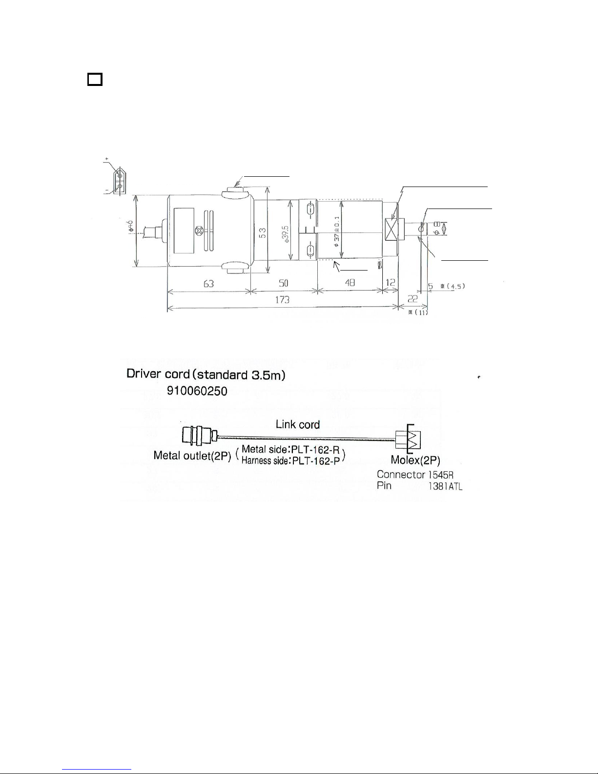
1 Screwdriver unit(MO-1330、MO-1350A)
Note)※( )The size is applied to special type MO-1330.
①Screwdriver cord 910060250(optional)
Transmits input / output signals.
driver side : surgical knife connecter 1545R / surgical knife pin 1381TR
controller side : metal outlet 2P PLT-162-R (panel side : PLT-162-P)
②Brush cap
Fixes and protects brush. If turned clockwise,brush cap tightens; if turned counterclockwise, it loosens.
③Holder
Please tighten one-page driver's center of the gripper with 5~8 N.m.
④Output shaft
Transmits screwdriver rotationn to bit.
①
(CONNECTOR FOR DRIVER)
CONNECTOR(OSU) 1545P
PIN (OSU) 1380TL
Terminal
Spanner ( opposete 32mm )
② Brush Cap
④Output shaft
③Holder
※Output axis φ6
Specification
φ3.5H7 ※(φ3H7)
①
-2-
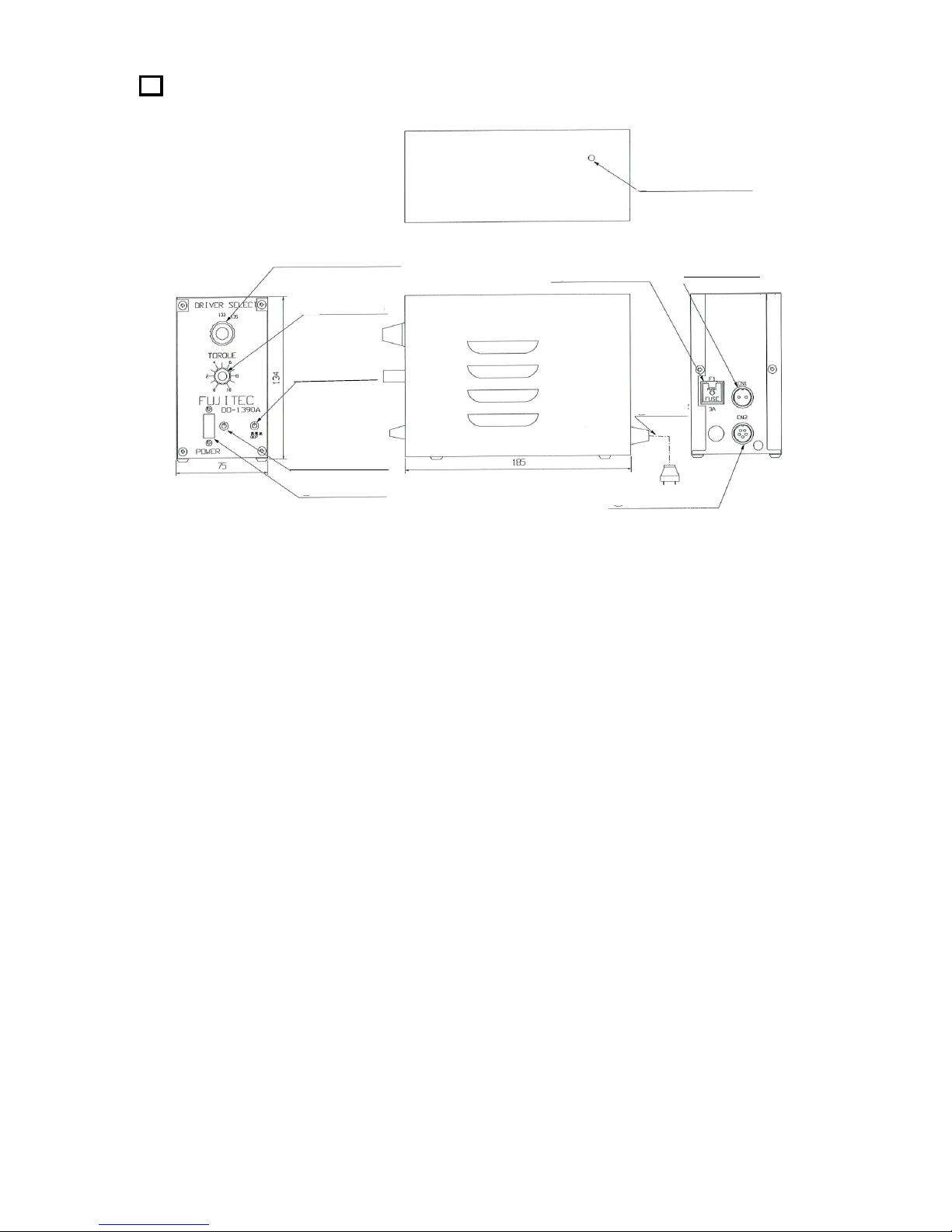
2
Controller(DO-13390A)For MO-1330・1350
①Screwdriver select switch
Set to screwdriver model No.
②Torque volume
Used to change torque.
③Power switch(POWER)
Used to ON/OFF power of control unit.
④Power indicator
Light while power control unit is ON.
⑤Overcurrent indicator lamp(OCP)
⑥Metal outlet(2P)
Used to connect to screwdriver.
Panel side :PLT-162-R Harness side : PLT-162-P
⑦Fuse holder (3A)
Used to protect and replace fuse.
⑧Metal outlet(5P)
Connecter to input/output signals.
Panel side :PLT-165-R Harness side : PLT-165-P
⑨Power cord
Plugged into AC100V power source.
⑩Adjustment at motor lock time
Can it tighten and the following maintenance officer be adjusted.
⑩Adjustment
at motor lock
⑥ Metal outlet
⑦Fuse holder
⑨
Power
⑧Metal outlet
③Power switch
④Power indicator
⑤
Overcurrent
indicator
①Screw driver select switch
②Torque
volume
-3-
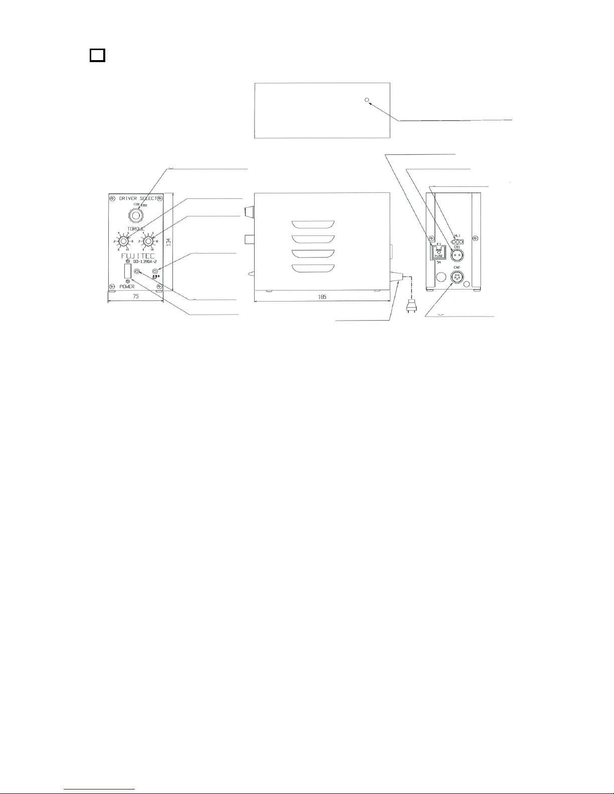
3
Controller(DO-1390A-2) For MO-1330・1350
①Screwdriver select switch
Set to screwdriver model No.
②Torque volume 1
Use to change torque.
③Torque volume 2
Use to change torque.
④Power switch(POWER)
Use to turn ON / OFF power of control unit.
⑤Power indicator
Light while power of control unit is ON.
⑥Overcurrent indicator lamp(OCP)
⑦Torpue change switch connector(3P)
Torque 1 and torque 2 can be switched.
⑧Metal outlet(2P)
Connected to input/output signals.
Panel side : PLT-162-R Harness side : PLT-162-P
⑨Fuse holder(3A)
Used to protect and replace fuse.
⑩Metal outlet(5P)
Connected to input/output signals.
Panel side : PLT-165-R Harness side : PLT-165-P
⑪Power cord
Plugged into AC100V power source.
⑫Adjustment at motor lock time
Can it tighten and the following maintenance officer be adjusted.
⑫Adjustment at motor lock
⑨Fuse holder
⑧ Metal outlet(2p)
⑦Torque switch
⑩Metal outlet
⑪Power cord
①Screwdriver select switch
②Torque volume1
⑥Overcurrent
indicator lamp
③Torque volume2
④Power switch
⑤Power
indicator
-4-
2.Precautions for Use
① Do not drop screwdriver unit and control unit or hit them against other substances.
② Keep the screwdriver free form water and oil.
③ Do not operate screwdriver select switch while screwdriver is working.
④ Never short-circuit screwdriver output terminal.
⑤ Be sure to perform daily inspection and maintenance. If any trouble should occur, please repair the unit
as soon as possible.
⑥ No modification is allowed.To ensure safe use, never provide screwdriver unit and controller with any
modification.
3.Preparation before Use
■
How to install
①
Installation requirements
Do not install the unit near Heating element.
Do not subject it to direct sunrays.
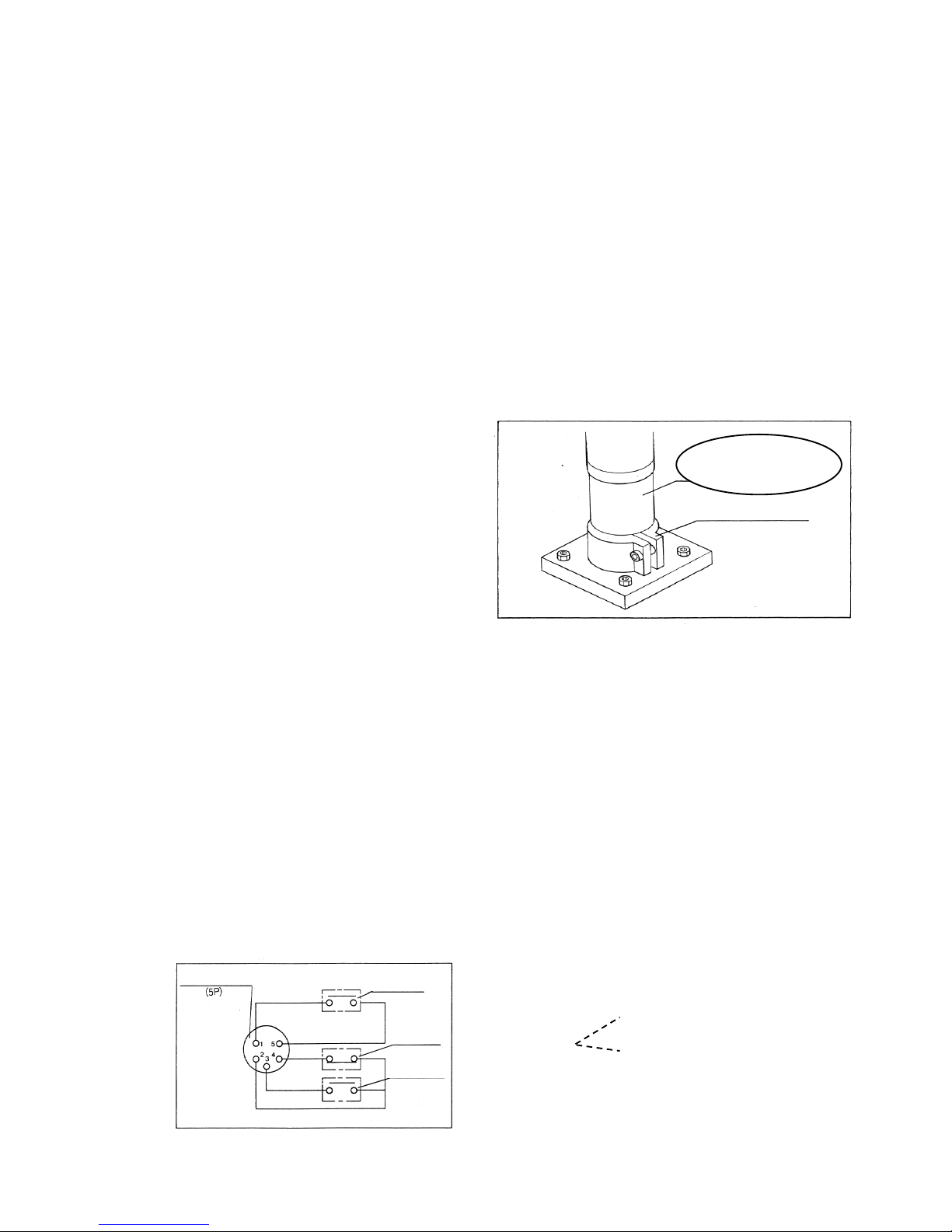
② Fixing screwdriver unit
Fixing screwdriver unit to screwdriver holder
using screwdriver grip.
※Use split type screwdriver holder.
■
How to connect
①
Check that power switch on controller is OFF.
② Plug power cord on the back of controller into AC100V power supply outlet.
③ Plug screwdriver cord into metal outlet (2P) on the back of controller.
【Caution】Be sure to use exclusive controller.
※DO-1390A,DO-1390A-2 : 2P metal outlet (For MO-1330・1350)
④ Connect input signal (start signal ) to input/output terminal (metal outlet ,5P )
on the back of controller. Input signal must be no-voltage contact signal.
【Caution】If several-units are used at a time each input signal must be provided through respective contact.
⑤ Complete signal can be obtained through input/output terminal.
Load capacity for complate signal must be kept below AC100V 0.1A.
⑥Input/output signal connection diagram
Start Signal・・・
Input signal terminal (1-5)
Output signal terminal (2-3)
(Relay A contact)
Input signal terminal (2-4)
(Relay B contact)
Metal outlet (5P)
Panel side : PLT-165-R
Harness side : PLT-165-P
Complete
Signal
Please tighten one-page
driver's center of the gripper
with 5~8 N.m
Holder
Start signal
extermal
Complete
B contact
Complete
A contact
-5-
 Loading...