

Page 1

CONTENTS
Contents . . . . . . . . . . . . . . . . . . . . . . . . . 1
Safety Precautions . . . . . . . . . . . . . . 2 - 4
Getting Started. . . . . . . . . . . . . . . . . . . . . 5
S pray Pattern . . . . . . . . . . . . . . . . . . . . . .6
Spraying Technique . . . . . . . . . . . . . 7
Aircap Selection . . . . . . . . . . . . . . . . . . . 8
Viscosity Guide . . . . . . . . . . . . . . . . . . . . 9
Latex Paint . . . . . . . . . . . . . . . . . . . . . . . .10
General Cleaning . . . . . . . . . . . . . . . . . . . . 1 1
Finish Problems . . . . . . . . . . . . . . . . . .12
Filter Replacement. . . . . . . . . . . . . . . .12
S pray Gun Problems . . . . . . . . . . . .13 - 14
Needle Packing Nut . . . . . . . . . . . . . . . 15
Cleaning Fluid Passages . . . . . . . . . . . 16
Turbine Care and Maintenance . . . . . . . 17
Parts Diagrams. . . . . . . . . . . . . . 18 - 21
Spray Gun Holder. . . . . . . . . . . . . 22
Service Information. . . . . . . . . . . . . 23
Warranty Information . . . . . . . . . . . . . . 24
CE Declaration . . . . . . . . . . . Back Cover
Page 2
Please read these instructions carefully before using the equipment
GROUNDING
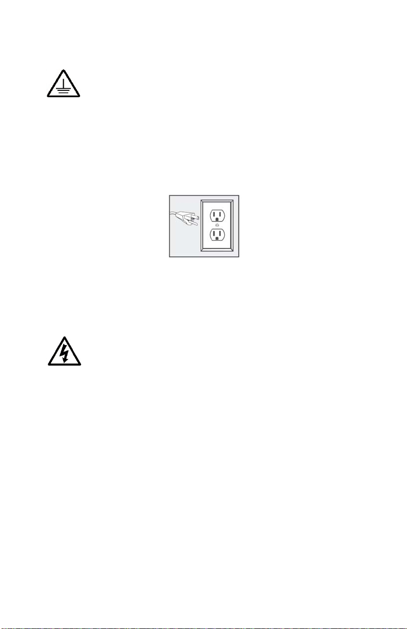
This appliance must be grounded. If it should malfunction or break down,
grounding provides a path of least resistance for electric current to reduce
the risk of electric shock. This appliance is equipped with a cord having
an equipment-grounding conductor and grounding plug. The plug must
be inserted into an appropriate outlet that is properly installed and grounded
in accordance with all local codes and ordinances.
Please Note* For UK, Australia, Asia etc. your voltage will be
220-240v. Check the label on the base of the turbine to ensure
your unit is at the correct voltage for your location.
ELECTRIC SHOCK HAZARD
Improper connection of the equipment grounding conductor can
result in the risk of electric shock.
· Check with a qualified electrician or serviceperson if you are in doubt
as to whether the outlet is properly grounded.
· Use only a 3-wire extension cord that has a 3-blade grounding plug
and a 3-slot receptacle that accepts the plug on the product.
· An undersized cord results in a drop in line volt age and loss of power
and overheating.
· Do not modify the plug provided with the appliance. If it will not fit the
outlet, have a proper outlet installed by a qualified electrician.
· To reduce the risk of electric shock or injury, do not expose to rain.
· Never allow unit to freeze.
2 23
Page 3

· Always store the unit inside in a dry location. Store on the fl oor if in
a basement a basement setting.
· The operator must wear shoes and the fl oor must not be wet.
FIRE AND EXPLOSION HAZARD
Turbine must not be used in an area contaminated by volatile or
fl ammable materials since sparking can be expected in the normal operation of the motor. This could ignite the contaminants
causing a dangerous explosion.
· Do not spray fl ammable or combustible materials near an open
fl ame or sources of ignition such as cigarettes, motors, and
electrical equipment.
· Keep spray area well-ventilated. Keep a good supply of fresh air
moving through the area. Keep turbine in a well ventilated area.
· Do not spray turbine.
· Turn off and disconnect power cord before servicing equipment.
· Do not smoke in the spray area.
· Do not operate light switches, engines, or similar spark producing
products in the spray area.
· Keep area clean and free of paint or solvent containers, rags, and
other fl ammable materials.
· Fire extinguisher equipment shall be present and working.
· Sprayer generates sparks. When fl ammable liquid is used in or
near the sprayer or for fl ushing or cleaning, keep sprayer at least
20 feet (6 m) away from explosive vapors or spraying area.
· Ensure ground prongs are intact on sprayer and extension cords.
· Always disconnect unit from main supply when fi lling the paint
container.
· Never use 1,1,1-trichloroethane, methylene chloride, other
halogenated hydrocarbon solvents or fl uids containing such
solvents in equipment with aluminum wetted parts. Such use
could result in a serious chemical reaction, with the possibility
of explosion. Consult your fl uid suppliers to ensure that
the fl uids being used are compatible with aluminum parts.
Toxic fl uids or fumes can cause serious injury or death if
splashed in the eyes or on skin, inhaled, or swallowed.
· Read MSDS (Material Safety Data Sheet) to know the specifi c
hazards of the fl uids you are using.
TOXIC FLUID OR FUMES HAZARD
3
Page 4

· Always wear appropriate gloves and eye protection
· Always wear a respirator or mask. Read all instructions of the
respirator or mask to ensure that it will provide the necessary
protection against the inhalation of harmful vapors. Please also check
with the local jurisdiction.
· Paint, solvents, insecticides and other materials may be harmful if
inhaled.
· Store hazardous fl uid in approved containers, and dispose of it
according to applicable guideline.
· Do not stop or defl ect fl uid leaks with your hand or body.
EQUIPMENT MISUSE HAZARD
Misuse of equipment can cause serious injury or death.
· Never aim the spray gun at another person or animal. In the event of
injury, seek expert medical advice immediately.
· Do not operate or spray near children. Keep children away from
equipment at all times.
· Do not overreach or stand on an unstable support. Keep eff ective
footing and balance at all times.
· Stay alert and watch what you are doing.
· Do not operate the unit when fatigued or under the infl uence of drugs
or alcohol.
· Do not kink or over-bend the hose.
· Do not use the hose as a strength member to pull or lift the
equipment.
· Do not cover turbine case as this will restrict air to the intake and
result to overheating and premature failure of the motor.
· Do not carry turbine while spraying.
· Check the hose, hose connectors and power cord daily. Any worn or
damaged parts should be replaced immediately.
· Use only genuine Fuji Spray replacement parts.
· It is normal for the turbine air outlet (manifold) to become hot during
use, please allow your Fuji Spray turbine to cool for a few minutes
before removing the hose from the turbine manifold.
Prop 65 Warning for California Residents
WARNING: This product may contain chemicals known
to the State of California to cause cancer, birth defects, or
other reproductive harm.
4
Page 5

GETTING STARTED
Please register your Fuji Spray Product at www.fujispray.com/product-registration
NOTE: Throughout this Manual we have used the generic word ‘Paint’ to
describe all and any coatings. Please substitute the word ‘Paint’ for
whatever finish or coating you are spraying.
Your Fuji Spray M-Model Gun has been adjusted at the factory and is
ready for spraying. To clean out any impurities that may have accumulated during assembly or shipping, we recommend spraying a small
quantity of clean paint thinner through the gun. Before tackling any
serious spraying, experiment with the Gun on a scrap piece of wood
until you become familiar with all the controls.
HOSE CONNECTION
Connect the Hex Nut at the end of the Hose (female connector) to the
Turbine Air Outlet. It is not necessary to use a wrench to tighten this
hex nut.
AIR CONTROL VALVE
The Air Control Valve 2032 is located on the Hose next to the brass
Quick-Connect. It provides you with a means of controlling the air flow
through the Gun. It offers you fingertip control when you need it to
reduce bounceback and overspray. There is one thing to remember
about the Air Control Valve - it is the ‘last in the chain’ after...
1) Thinning the paint
2) Adjusting the shape and size of the spray pattern
3) Adjusting the flow of paint through the gun.
After performing these operations, you should spray a few passes onto a
scrap piece of plywood or cardboard. This will allow you to determine if
the paint (generic word for any type of coating) levels nicely. If there is
‘orange-peel’ then you must thin the product more. Once the gun is
producing a perfect finish with full air, you may then experiment with
turning the air down until bounceback is reduced to a mininum. With
heavier paints (such as latex) spraying may be done with the Valve fully
open (or even removed).
PLASTIC DIAPHRAGM
The 1 Quart pressurized Cup has a plastic Diaphragm 2096 (not found in
the Gravity Spray Gun). This Diaphragm prevents paint from entering the
Pressure Tube 2024. The small air hole in the Diaphragm should not be
placed directly below the air hole in the Nipple. Position the Diaphragm
hole to the rear of the Cup. The Spray Gun can be turned to different
angles when spraying but never turned more than horizontal.
5
Page 6

CHANGING SIZE & SHAPE OF THE P A TTERN
A) Loosen the Collar #1. Turn the Aircap #2 to the horizont al position. This setting produces a vertical spray pattern. Always make sure
the Collar is snug tight.
B) Setting the Aircap in a vertical position produces a horizont al
spray pattern. To lock it in position, tighten the Collar #1 clockwise
until it stops turning.
C ) For smaller pattern sizes, the Aircap can be set at horizontal or
vertical. Turn the Pattern Control Knob #6 (at the rear of the Gun). This
knob adjusts the size of the fan pattern from large to small round and
anywhere in between. For regular spraying, the general setting is
about 6”-8” wide from 8” distance away . This is a personal preference.
If you turn the fan pattern down to a smaller round spray pattern you
will have to reduce the amount of fluid by turning the Fluid Knob #7. If
you do not do this, you will get runs. You can use this much smaller
pattern to spray spindles or the side of a board.
To set the fluid output, turn the Fluid Knob #7 clockwise until you
cannot pull the trigger. Then unscrew it a little until a small amount of
fluid comes out of the Nozzle when you depress the Trigger . Once you
set the fluid to your liking, you can leave it in this position. Always
remember that if there is not enough fluid (paint) you can turn the Fluid
Knob counter-clockwise for more output.
6
Page 7
SPRA YING TECHNIQUE
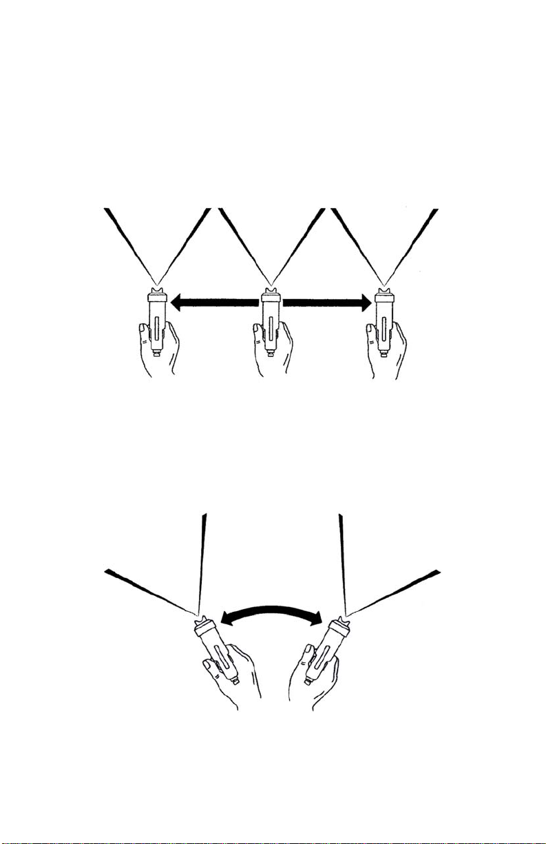
The spraygun should be held perpendicular to the surface at all times.
HOLD THE GUN NO MORE THAN 8” (20cm) A WA Y FROM THE
SURFACE TO BE PAINTED. But closer is ok.
CORRECT METHOD
St art moving the spraygun in the direction you want to spray and press
the trigger. Between each successive p ass, overlap by about a quarter.
INCORRECT METHOD
Never, for any reason, point the spraygun directly at the face, or
head of a person.
718
Page 8
AIRCAP SET SELECTION
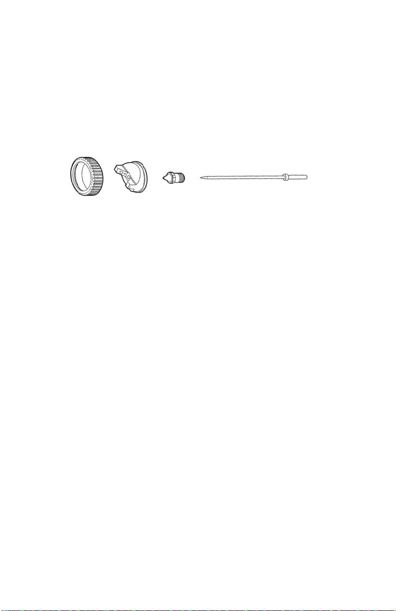
5 additional setups are available as accessories. Size No.3 is standard with all Fuji M-Sprayguns. No. 2, 3 or No. 4 can be used for any
type of fine-finishing application. The larger sizes such as No. 4 allow
for more fluid output. This is desirable when spraying fast drying
lacquers. It allows you to spray wetter to obtain better leveling.
AIRCAP SET - Part 7020
If you do not intend on spraying walls & ceilings then the only additional
setups you would ever need would be the No. 2 Fine and Medium No. 4.
No. 1 (Part 7020-1) .8mm (.031") SUPER-FINE OUTPUT
SHADING , ST AINS.
No. 2 (Part 7020-2) 1mm (.039") FINE OUTPUT
SHADING , ST AINS, WA TERBORNE COA TINGS.
No. 3 (Part 7020-3) 1.3mm (.051") FINE - MEDIUM OUTPUT - STANDARD
WA TER-BASED LACQUERS, ACRYLICS, POL YURETHANE, ST AINS.
No. 4 (Part 7020-4) 1.5mm (.059") MEDIUM OUTPUT
Similar to No. 3 but more coverage. Best for AUTOMOTIVE ENAMELS,
NITROCELLULOSE LACQUER and LATEX for a finer finish. Also ideal for
V ARNISHES, PRIMERS, OIL-BASED P AINTS.
No. 5 (Part 7020-5) 1.8mm (.070") HIGH OUTPUT
Larger surfaces, thick layers, spotted effects. SEALERS, VARNISH,
POLYURETHANE, OIL BASED P AINTS, ENAMELS, EPOXY, PLASTIC,
ADHESIVES, FLOOR P A VING PAINTS, LA TEX , ETC.
No. 6 (Part 7020-6) 2mm (.078") EXTRA HIGH OUTPUT
Very heavy flows, fast coverage. ST ONE FINISH P AINTS, TEXTURE
COA TING , INDUSTRIAL PRIMERS, MUL TI-FLECK PAINTS, LA TEX (on
walls, ceilings) ETC.
8 17
Page 9

VISCOSITY GUIDE
A Viscosity Cup is included with your Fuji M-System.
To test the viscosity of the paint material, fill the Viscosity Cup to the
brim and time how long it takes for the liquid to empty out through the
hole. We recommend you experiment to find the ideal viscosity for
your application and record the information for the next time.
Always check with the manufacturer of the coating for assistance in
thinning for spraying. If their product is only designed to be brushed,
they may not be too helpful. But remember that any type of coating
can be sprayed if it is thinned correctly and you have installed the
ideal aircap set.
The chart below illustrates how many SECONDS it should take for the
material to flow out of the viscosity cup. This is only an approximate
guide.
Auto Cellulose 18 - 20 Primers 30 - 40
Lacquers 18 - 20 Sanding Sealers 20 - 22
Enamels 20 - 25 Stains Undiluted
Latex 20 - 30 Creosote Undiluted
Oil-based 20 - 25 Polyurethanes 20 - 25
We suggest thinning around 25% to begin with but this may contravene the air quality control laws for your location. The solvent used for
thinning is usually the solvent mentioned on the can (instructions for
‘cleaning the brushes’). However, please check with the coatings
manufacturer.
HVLP spraying is more friendly to the environment than most methods
of spraying. It reduces appreciably the amount of unnecessary misting
and fogging (overspray) associated with high-pressure spraying.
Spraying with Nitrocellulose lacquer can be hazardous. The lacquer,
fumes and overspray are toxic, flammable and explosive. If
spraying must be done inside an enclosed area, ventilate well. Spray
close to an open window or door and situate a fan to draw out the
fumes (an explosion-proof motor and explosion-proof lighting will be
necessary).
Please check with the local Authority having jurisdiction on
this matter.
9
Page 10

A WORD ABOUT LA TEX
Although latex paint was never originally intended to be sprayed, a
professional finish can be achieved by following a few simple rules.
(Please do not confuse latex with the newer water-based coatings).
For work such as cabinetry or trim, our equipment can be used
successfully with latex paint. The latex will have to be thinned with
WATER - approximately 20-30% depending on the brand of
paint. And to improve the finish even more, you can use an additive
that will slow down the drying process so that the paint levels out
nicely . One product available is FLOETROL from the FLOOD Company in Ohio. In the USA Call 1-800-321-3444 for your nearest
supplier. (In the U.K. 0845-0618899).
The ideal Aircap size setup is either the No. 4 or No. 5 for household
trim, louver doors etc. The Latex paint should be ‘finish-quality’ and
not a cheaper grade.
When spraying Latex, please adjust the Fluid Knob to limit the paint
to a finer spray . This will increase the ratio of air to p aint and result
in better atomization and a beautiful finish. (Factually speaking, it
doesn’t increase the ratio of air to paint but does the opposite - it
allows the air atomizing power to work on less paint thereby improving the quality of atomization). Also, it is usually help ful to remove
the air control valve so that more air passes through the spraygun.
Finally , adjust the p attern to a maximum size of 8” - 9” (20cm) smaller is ok.
Although it is possible to use our equipment for house painting
(walls), and many end users do, we feel that an airless gun or power
roller is better suited for that kind of job. However, if you decide to do
this kind of work, you will need the #6 Aircap set.
Remember, when you buy a can of p aint, lacquer, polyurethane,
varnish etc. over the counter, it will most likely be formulated for
brushing. That means, it will be too viscous (thick) and will require
thinning to spray successfully . This is true even when spraying is
mentioned on the label of the can. Check with the manufacturer of
the coating to obtain advice on thinning their product.
Page 11

GENERAL CLEANING
To clean the gun after each use, empty all paint from the Cup. Use a
solvent-soaked rag to clean the residue in the Cup. Then, spray some
clean solvent through the Gun into a clean rag (to avoid filling the room
with unnecessary spray) or a bucket. Repeat until the inside of the
fluid passages in the Gun, Metal Fluid Tube etc. are clean. Use the
wet rag to wipe off the Aircap and tip of the Fluid Nozzle. The Aircap
can be soaked in thinner.
Do not restrict the Fluid Nozzle when cleaning - this will drive thinned
paint up the pressure tube and into the spraygun which is undesirable.
If this type of cleaning is done while the paint is still wet in the Gun, it
should be all that is necessary to keep the Gun clean enough for next
time. Do not leave liquids in the Cup overnight or for long periods.
PLEASE DO NOT USE A WIRE BRUSH OR ANYTHING METAL T O
CLEAN THE GUN OR CUP AS THIS WILL CAUSE DAMAGE.
DO NOT disassemble the Cup Assembly - Threads in your cup
have been sealed at the factory to prevent leakage under
pressure.
The standard 1 quart (1000cc) Cup can be used with most coatings
(including water-based). Also available as an accessory is our 2093T
Teflon-coated Cup.
CAUTION: Never soak the complete Spraygun in solvent as this
removes the grease from the parts and distributes thinned paints
throughout the air passages. It could also damage internal parts such
as the Spindle Valve or Valve Seals. It may however , be necessary
sometimes to soak the Aircap No. 2 and Nozzle No. 3. You may soak
only the metal parts in solvent and clean with the soft bristle
Cleaning Brush 9045. To reassemble, first oil or grease all moving
and threaded parts.
CAUTION: Do not store the Gun with the cup clamped down
hard as this will cause the gasket to flatten out. Do not lay the
gun down on its side with liquid material in it.
PLEASE SEE PAGE 14 FOR MORE ON CLEANING
11
Page 12

FINISH PROBLEMS
ORANGE PEEL - If the finish is rough and resembles orange peel then
the material is too thick. (Or perhaps you have the Air Control V alve
turned down - please check that it is fully open). The ‘paint’ will not
atomize properly and the surface will be spotty . To remedy this, add
more thinner (or appropriate solvent). For fast drying products such as
lacquers, you may also want to add a lacquer retarder . This will slow
the drying time allowing the material to flow out and level nicely .
Retarders are available for other coatings too, such as Penetrol for Oilbased paints or Floetrol for Latex house paints. These products go
under different names such as Flow-Out Additives etc. Please check
with the coatings manufacturer.
NOTE: With the newer water-based materials ‘orange peel’ is usually a
result of spraying on too thick a film. Try spraying an extremely
THIN FILM, but still WET coat. With most other coatings, orange
peel is caused by material being too thick or not enough atomizing
power. This is why we suggest leaving the air control valve fully open
when experimenting with a new coating material, otherwise it will
cause confusion. If the the air control valve is fully open (or perhaps
removed for Latex spraying) then orange peel can only be one cause the material is too thick and must be thinned.
GRITTY FINISH - If the material is too thin, it is likely to run or be
over-atomized, producing a rough gritty finish. Try thinning the product
less and spraying a wetter coat.
FIL TER(S)
The M-Series Turbines has 2 Filters. T o remove, simply pull the Filters
out from the bottom of the Filter Enclosures. Wash in solvent and dry
before replacing.
All Fuji Filters are a friction fit. The Filter must fill the entire Filter
Enclosure.
One of the Filters is Fine and one Coarse - the Fine Filter is installed
to the Left Side and the Coarse to the Right Side (as seen looking at
the front of the Turbine where the Hose is connected).
12 13
Page 13

SPRA YGUN PROBLEMS
NO P AINT (OR VERY LITTLE P AINT)
The air passing through the Pressure Tube 40 to pressurize the Cup is
blocked. This means that either the T ube itself, the Check V alve, or
one of the two Nipples are blocked. A pipe cleaner can be used for
cleaning the hole in the Nipple.
• Pressurizing Tube and/or Nipples are blocked - COMMON
• The Cup is not tightened down sufficiently by the Lever or the
Cup Gasket is worn and leaking air
• The Cup is empty
• The metal Fluid Tube is blocked with paint - RARE
• The Fluid Coupler is blocked with paint - RARE
UNEVEN SPRA Y P ATTERN
One of the holes in the Aircap may be blocked. Or, the paint could be
dirty and is partially blocking the Fluid Nozzle. Remove the Aircap and
clean by soaking in solvent and using the soft Bristle Brush or a rag.
NEVER use metal objects to clean holes in the Aircap.
LEAKAGE
If paint material comes out of the Fluid Nozzle without pulling the
Trigger...
• The Needle is not seating in the Fluid Nozzle properly
• The Needle Packing may be too tight preventing the
Needle from moving - See Page 15 Packing Adjustment
• Foreign matter trapped between Needle and Fluid Nozzle
• The Needle or Fluid Nozzle could be damaged or worn
• Loose Fluid Nozzle
• Wrong Nozzle size installed
CUP LEAKS
• Oil above and below the Lever to smooth the Lever action
• Change Gasket/Diaphragm
• Leak around Nipple - use Loctite to seal
• Leak around Side Pins - use Loctite to seal
• Leak through Lid - remove Nut under Lid - use Loctite
Page 14

THE TRIGGER IS SLUGGISH
• The Needle Packing is too tight - see ADJUSTING THE
NEEDLE PACKING. Page 15
• Bent Needle
POOR SPRA Y P A TTERN
• Damaged Needle or Nozzle
• Nozzle is clogged
• Air holes in Aircap clogged
• Gun too far from surface (max. 8” - 20cm)
P AINT A T THE AIR NOZZLE HOLES
• The Fluid Nozzle is loose and material is leaking around it tighten with the supplied Wrench
• Paint is entering the gun via the Pressure Tube and being
blown through the Barrel to the Aircap
GUN SPRA YS IN A PULSA TING MANNER
• The Needle Packing has worn a little or is loose. Tighten
• The Cup is almost empty
• The Cup Lid is not tight - air is escaping
• The clear Plastic Pressure Tube is leaking air. Replace
• The Pressure Tube and/or Nipple is clogged. Clear or replace
EXCESSIVE OVERSPRA Y
• The spray pattern size is too large for the item being sprayed
• The Gun is being held too far away - should be 8” max. (20cm)
• Trigger on and off as you pass over the edges of the item
• The product is too thin - try thinning less
• Reduce the air by turning the Air Control V alve to the point
where overspray is minimized but the finish still looks good
• For ideal and comfortable spraying conditions, you should
install an extraction fan.* If you are spraying a flammable,
combustible product such as nitrocellulose lacquer, you must
install an explosion-proof fan (and explosion-proof lighting and
switches)
* Please check with the local jurisdiction on this matter.
14
Page 15
LEAKAGE FROM THE NOZZLE
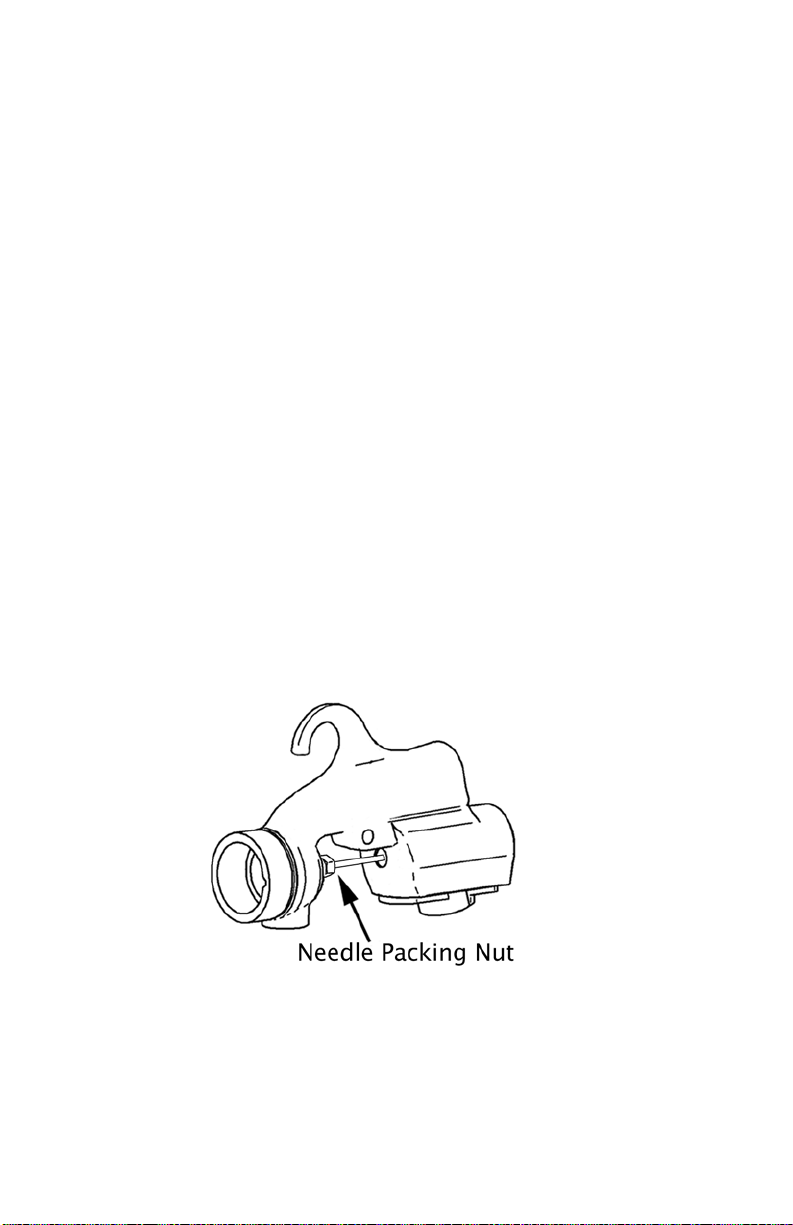
This occurs when the Needle Packing Nut is too tight compressing
the Needle Packing #12 tightly around the Needle.
Half fill the cup with water. Attach the Gun to the Hose and turn on the
Turbine blower . Pull the T rigger and release. Check the Nozzle for
water spurting out.
Using the supplied wrench, GENTLY loosen the Nut (1 or 2 degrees
only at a time). This is a very sensitive adjustment. Again pull the
Trigger and release. Wipe away the water in between adjustments.
Repeat until no water is seen at the Nozzle Hole.
LEAKAGE FROM THE NEEDLE P ACKING NUT
This occurs when the Needle Packing Nut is too loose.
Half fill the cup with water. Attach the Gun to the Hose and turn on the
Turbine blower . Using the supplied wrench, GENTLY tighten the
Needle Packing Nut 1 or 2 degrees only . This is a very sensitive
adjustment. Wipe away the water in between adjustments. Repeat
until no water is seen where the Needle passes through the Needle
Packing Nut.
It is a good idea to apply Light Machine Oil or V aseline to the Needle
Shaft where it passes through the Needle Packing Nut and work it in
and out by pulling the Trigger back and forth. This will lubricate the
Needle Packing #12.
1510
Page 16

CLEANING FLUID PASSAGES
To clean, flush appropriate solvent (refer to material manufacturer's
cleaning recommendations) through the Spraygun while the paint is
still wet inside the gun. If this type of quick cleaning is performed
frequently , the Spray Gun will function well for many years. 99% of
problems with a Spray Gun stem from clogs in the fluid passages and
(perhaps more important), the Pressure Tube air passages. Please
see Page 13... No Paint (or very little paint).
CLEANING BEHIND THE FLUID NOZZLE
Remove the Collar #1 and Aircap #2.
Using the supplied wrench, remove the Fluid Nozzle #3. Once the Fluid
Nozzle #3 is removed it is relatively easy to clean behind it with the
cleaning brush and soapy water.
For a more thorough cleaning, remove all parts at the front of the barrel
- Collar, Aircap, Fluid Nozzle etc. You may soak the parts in solvent.
Also, remove the Fluid Knob 7, Spring 9 and Needle Assembly 8 from
the rear of the gun. The Needle Assembly can then be soaked and
later wiped clean.
PLEASE DO NOT SOAK THE WHOLE GUN IN ANY LIQUID - THIS IS
NEVER NECESSARY OR ADVISABLE.
CLOGGED GUN - THE FLUID COUPLER
If the Fluid Coupler 16 is clogged with dried paint it must be cleaned
while in place in the gun. The Fluid Coupler 16 should never be
removed. Remove the cup assembly by loosening the Nut at the top
of the Assembly. Use the supplied Cleaning Brush to unclog the inside
16
Page 17

TURBINE CARE AND MAINTENANCE
FIL TER(S)
It is important to clean or replace your filters regularly. Operating the
Turbine unit with clogged or dirty filters will cause the Turbine to overheat
and result in premature failure. The Fuji HVLP Turbines have either 1 or
2 Filters. To remove, simply pull the Filters out from Filter Enclosure.
Wash in warm soapy water and dry before replacing.
All Fuji Filters are a friction fit. The Filter must fill the entire Filter Enclosure. NOTE: Semi-PRO and Hobby-PRO Turbines have two square fil-
ters, fine and coarse. The fine Filter is installed to the left side and the
coarse to the right side (as seen looking at the front of the Turbine where
the Hose is connected).
Cleaning your filters regularly is essential to maintaining your
Turbine. It is always a good idea to have a spare pair of filters on
hand.
Turbine Filter part numbers:
Semi-PRO or Hobby-PRO Turbine (square shape filters) - Part # 4009-2
All HVLP Turbines are designed for intermittent use. When taking a
break between coats or stepping aside to refill your cup, it’s good practice
to turn the Turbine off during this time. This allows the machine to cool
off.
When spraying, always ensure that the Turbine unit is at least 15 feet
away from spray project and in a well ventilated area. This will prevent
any overspray or debris being ingested into the Turbine. Failure to do
this may cause the filters to clog, resulting in damage to the internal
motor.
It is a good idea to make use of the Turbine Wireless Remote (Accessory
part # 3072). This device allows you to turn the Turbine unit on/off for
your convenience without having to walk back and forth to the Turbine.
If you experience a problem with your Turbine unit, please DO NOT try to
open and service the Turbine yourself. Contact us for technical assistance.
If it is an issue of no power, check your power outlet. Also, try re-setting
the Breaker on the back of the turbine by pressing it once.
Page 18
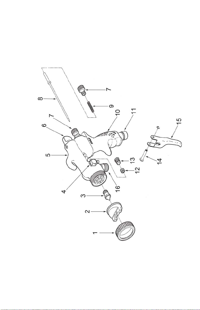
FUJI M-MODEL SPRAY GUN
Page 19
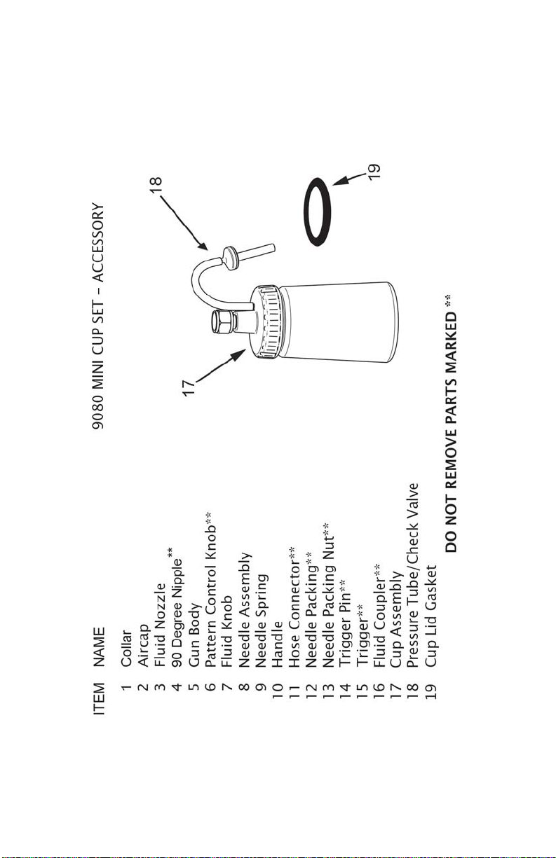
19
Page 20
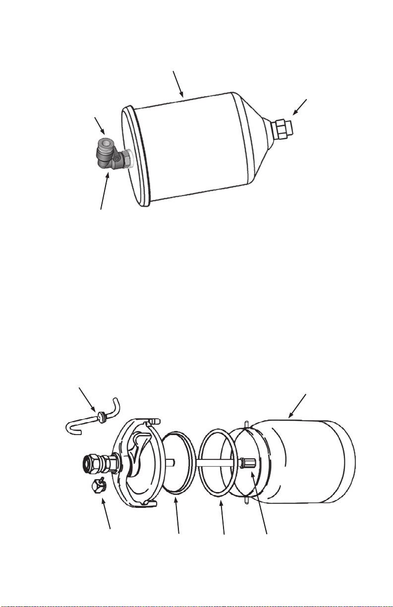
ϰϯ
&ŝƚƐƚŽ
hͲdƵďĞ
;EŽƚ^ŚŽǁŶͿ
WƵƐŚƚŽƌĞůĞĂƐĞ
WƌĞƐƐƵƌĞdƵďĞ
'Zs/dzhW^^D>z
44
ED
ƵƉ>ŝĚ'ĂƐŬĞƚ
ŝĂƉŚƌĂŐŵ
ϵϬĞŐƌĞĞEŝƉƉůĞ
WƌĞƐƐƵƌĞdƵďĞ
WĂŝŶƚ^ƚƌĂŝŶĞƌ
ϭYƚƵƉ;ϭϬϬϬĐĐͿ
'ƌĂǀŝƚLJƵƉ;ϰϬϬĐĐͿ
dƵďĞ&ŝƚƚŝŶŐ
ϰϬ
hW^^D>zϮϬϵϱ
ϯϵ
ϯϳ
/dD
ϯϴ
ϯϵ
ϯϴ
20
ϰϬ
ϰϭ
ϯϳ
ϰϮ
ϰϯ
ϰϰ
ϰϮ
ϰϭ
Page 21
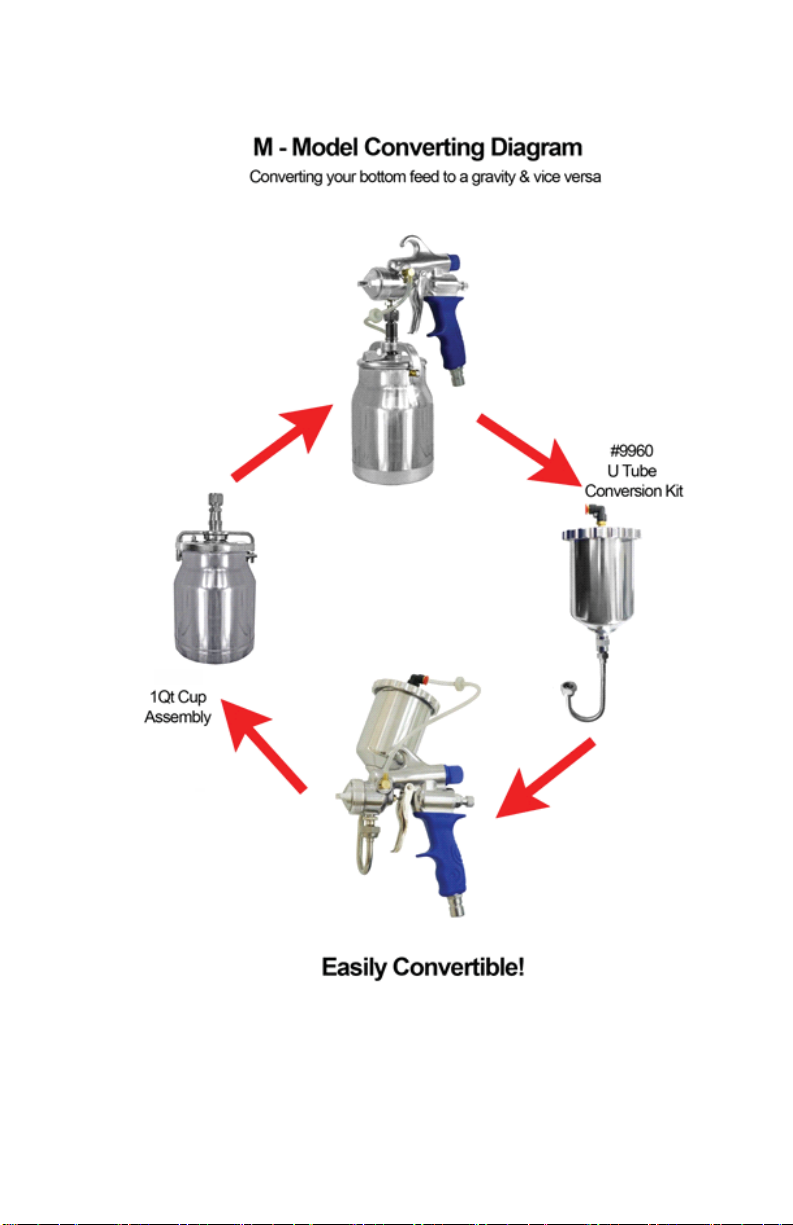
#2095
21
Page 22
22
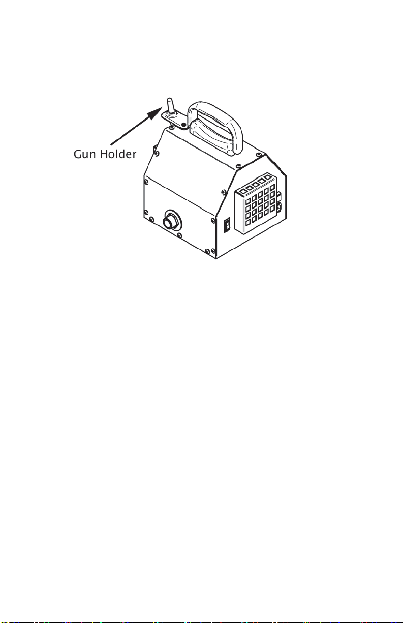
GUN HOLDER INSTALLATION
The 2 holes on the top of the Holder require the Black Machine
Screws and Washers. These Screws fit into Threaded Inserts in
the Metal Case. Do not overtighten - snug is fine.
The single Silver-Colored Screw must be installed to the single
hole on the side of the Gun Holder. Once again, please do not
overtighten this screw - snug is fine.
GUN HOLDER USE
Place the Hose Connector 11 (base of the Gun Handle) over the
shaft of the Gun Holder shown in above illustration. Please
ensure it is fully set down to the base of the Shaft. The Spray
Gun will now sit stationary. The Gun can be left on the Holder for
any length of time. It is a convenient resting place between
spraying.
GUN HOLDER
Page 23

For SERVICE & PARTS
USA
Cogent Bathtub Refinishing Coatings
Phone: 862-238-7224 Online: www.cogentcoatings.com
hvlp.net
Phone: 800-650-0930 Online: www.hvlp.net
Phelps Refinishing
Phone: 800-377-5662 Online: www.phelpsrefinishing.net
Paint Sprayers Plus
Phone: 877-293-5826 Online: www.paintsprayersplus.com
CANADA
Fuji Spray
Phone: 800-650-0930 Local: 416-650-1430
hvlp.ca
Phone: 800-650-0930 Online: www.hvlp.ca
UNITED KINGDOM
Axminster Power T ool Centre. Axminster, Devon, England
Phone: 01297 33656
AUSTRALIA & NZ
Spraychief Industries Campbellfield, Victoria 3061
Phone: 03-9357-8788
PUERTO RICO
Eagle T ools Mfg. Corp San Lorenzo, Puerto Rico, 00754
Phone: 787-736-0444
Fra-Marson Warehouse Distributors. San Juan PR, 00926
Phone: 787-761-4810
RUSSIA
varnishop.ru St. Petersburg, Russia
Phone: 812-242-8040 Online: www.varnishop.ru
Copyright © 2014 Fuji Spray® Toronto. Canada
Page 24

Fuji Limited 2 Year W arranty
Fuji Industrial Spray Equipment Ltd. (“Fuji”) provides a 24 month limited
warranty on the product to the original purchaser effective from the date
of purchase against defects in materials and workmanship.
The warranty does not cover damage or defects arising as a result of
abuse, misuse, accident, negligence, malfunction, corrosion, normal
wear and tear, inadequate or lack of spray gun or other aspects of
maintenance of the product, damage arising from improper assembly ,
installation or operation, or damage arising from the product being
used for a purpose other than that for which it was designed or
intended. The warranty is void if repairs to the product are made or
attempted by anyone other than Fuji or its authorized agent, or if any
modifications to the product are made or attempted.
Purchasers located in North America must obtain a Return Material
Authorization number by calling Fuji at 1-800-650-0930 before
returning the product to Fuji or its designated representative. Purchasers located outside North America must contact the vendor from
which they purchased the product. In all instances purchasers must
return the product together with proof of purchase and with shipping
prepaid. For valid warranty claims the product will be returned to the
purchaser with shipping prepaid.
This is the only warranty provided by Fuji with respect to the
product and is in lieu of any other warranties, express or
implied, including but not limited to any warranty of merchantability or fitness for a particular purpose. Fuji’ s sole obligation
under this warranty shall, at its option, be to either repair or
replace a product determined by Fuji to be defective. In no
event shall Fuji be liable for loss or profits, incidental or consequential damages, injury to any person or property , or any
other damages of whatsoever nature.
24
 Loading...