

Fujing Tech FJ 007 User Manuals
Person or Vehicle
ITEM FJ 007Wireless Alert
FCC ID:D4CFJ007
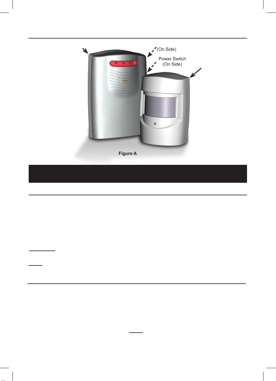
Components and Controls
Receiver
Figure A
DC Jack
(On Side)
Power Switch
(On Side)
Sensor
Setup Instructions
Installing Batteries
1. Using a screwdriver (not included),
remove the Battery Cover of the
Sensor, and insert three AAA
batteries (not included), positioning
in the correct polarity as indicated
in the battery compartment.
Replace the Battery Cover.
CAUTION: Position batteries in proper polarity and do not install batteries of different types,
charge levels, or capacities together.
Note: An optional 6 volt, 200 mA power adapter (not included)
can be used to power the Receiver instead of batteries.
2. Using a screwdriver (not included),
remove the Battery Cover of
the Receiver, and insert three C
batteries (not included), positioning
in the correct polarity as indicated
in the battery compartment.
Replace the Battery Cover.
Installing the Sensor and Receiver
Determine the location of the Sensor and Receiver. Choose locations
with no hidden wiring which would contact the mounting screws.
1. Considering the following when
choosing a location for the Sensor:
a. The passive infrared sensor detects
heat. Avoid aiming it towards
areas that produce heat such as
heater vents, windows where the
sun hits, or outdoor spotlights.
Page 2
2. Using hardware (not included), mount
the Sensor securely to a flat surface.
3. Place the Receiver within
120m of the Sensor.
Note: Obstructions may reduce
the receiving range.
 Loading...