

Petrol Powered Inverter Generators
User Manual
[Revision 5.0 May 2018]
READ THIS MANUAL CAREFULLY BEFORE USE – FAILURE TO DO SO MAY RESULT IN INJURY, PROPERTY
DAMAGE AND MAY VOID WARRANTY. • KEEP THIS MANUAL FOR FUTURE REFERENCE. • Products covered by
this manual may vary in appearance, assembly, inclusions, specifications, description and packaging.
The product is NOT supplied with engine oil, although traces of oil from the manufacturing
process may be present. It is essential to add adequate engine oil of the correct type to the
engine before use – see Checking and Changing Engine Oil. Failure to add engine oil will void the
product warranty.
E&OE ©2018 Fuji Micro / Genforce / Bäumr-AG

Petrol Powered Inverter Generators
It is important that you read and
General Work Area Safety
Use the equipment and accessories etc. in
Safety
Safety messages are designed to alert you to possible dangers or hazards that could cause death, injury or
equipment or property damage if not understood or followed. Safety messages have the following symbols:
You WILL be KILLED or
SERIOUSLY INJURED if you
do not follow instructions.
understand the instruction manual before
use and keep the manual in a safe place
for future reference. Safety information
presented here is generic in nature – some
advice may not be applicable to every
piece of equipment.
All safety precautions must be observed to
reduce the risk of personal injury when
operating the equipment.
The term "equipment" refers to your
product, be it electrical mains, battery or
petrol engine powered.
IMPORTANT – Handle the equipment
safely and carefully.
BEFORE USE - If you are not familiar with
the safe operation/handling of this
equipment, or are in any way unsure of any
aspect of suitability or correct use it for
your application, you should complete
training conducted by a person or
organization qualified in safe use and
operation of this equipment, including
fuel/electrical handling and safety.
WARNINGS
• Read all safety warnings and all
instructions. Failure to follow warnings
and instructions may result in electric
shock, fire and/or serious injury.
• Never run a petrol engine in confined
areas.
• Do not operate the equipment in
flammable or explosive environments,
such as in the presence of flammable
liquids, gases or dust. Engine and
equipment may create sparks or heat
that may ignite vapours, dust etc
• Keep clear of moving parts.
• This equipment may be a potential
source of electric shock if misused.
• Do not operate the equipment if it is
damaged, malfunctioning or is in an
excessively worn state.
• Do not allow others to use the
equipment unless they have read this
manual and are adequately trained.
• When using the equipment, basic
safety precautions detailed here m ust
always be followed to reduce the risk
of fire, electric shock, personal injury
and material damage.
• When wiring electrically powered
equipment, follow all electrical and
safety codes.
• Ensure all power sources conform to
equipment voltage requirements and
are disconnected before connecting
equipment.
You CAN be KILLED or
SERIOUSLY INJURED if you
do not follow instructions.
Work areas should be clean and well it.
Do not operate the equipment if
bystanders, animals etc are within
operating range of the equipment or the
general work area.
Personal Safety
Keep packaging away from children - risk
of suffocation! Operators must use the
equipment correctly. When using the
equipment, consider conditions and pay
due care to persons and property.
Prevent unintentional starting of the
equipment - ensure equipment and power
source switches are in the OFF position
before connecting or moving the
equipment. Do not carry equipment with
hands/fingers touching any controls.
Remove any tools or other items that are
not a part of the equipment from it before
starting or switching on.
Stay alert and use common sense when
operating equipment. Do not overreach.
Keep proper footing and balance at all
times. Do not use equipment when tired or
under the influence of drugs, alcohol or
medication. This equipment is not intended
for use by persons with reduced physical,
sensory or mental capabilities.
You must wear appropriate protective
equipment when operating, servicing, or
when in the operating area of the
equipment to help protect from serious
injury, including eye injury, inhalation of
toxic fumes, burns, and hearing loss.
Always wear eye protection. Protective
equipment such as respirators, non-skid
safety shoes, hard hat, hearing protection
etc should be used for appropriate
conditions. Other people nearby should
also wear appropriate personal protective
equipment. Do not wear loose clothing or
jewellery, which can be caught in moving
parts. Keep hair and clothing away from
the equipment.
If devices are provided for the connection
of dust extraction and collection facilities,
ensure these are connected and properly
used. Use of dust collection can reduce
dust-related hazards.
General Equipment Use and Care
Do not force the equipment. Use the
correct equipment for your application. The
correct equipment will perform better and
be safer within its design parameters. Do
not use the equipment if the ON/OFF
switch malf unctions – any equipment that
cannot be controlled with the ON/OFF
switch is dangerous and must be repaired.
You CAN be INJURED if you
do not follow instructions or
equipment damage may occur.
accordance with these instructions,
considering working conditions and the work
to be performed. Using the equipment for
operations different from those intended
could result in hazardous situations.
Before use, inspect the equipment for
misalignment or binding of moving parts,
loose components, damage or any other
condition that may affect its operation. If
damaged, have the equipment repaired by an
authorized service ce ntre or technician before
use.
Always keep the equipment and accessories
(cutting tools, nozzles, bits etc) properly
maintained. Keep the equipment, controls
and handles dry and free from dirt, oil and
grease.
Store the equipment out of reach of children
or untrained persons. To avoid burns or fire
hazards, let the equipment cool completely
before transporting or storing. Never place
the equipment in places where there are
flammable materials, combustible gases or
combustible liquids etc.
The equipment is not weather-proof, and
should not be stored in direct sunlight, at high
ambient temperatures or locations that are
damp or very humid.
Generator Use and Care
WARNINGS
• If the generator is for back-up power to a
house etc, it must be connected to the
building electrical system by a qualified
electrician and must comply with
relevant laws and electrical codes. If not
connected correctly, use of the
generator may present electrocution,
electric shock, explosion and fire
hazards.
• The generator creates high voltage and
current electricity. Do not connect
incompatible devices.
• Never insert any object other than
compatible connectors into any
generator output connector.
• Do not operate the equipment with wet
hands or clothing.
• When using the generator, ensure to
keep it and all connected cables away
from other electrical cables.
• Operate the generator on solid, level
surfaces only, with at least 1m (3')
between it and other equipment or
objects.
E&OE ©2018 Fuji Micro / Genforce / Bäumr-AG 2
Petrol Powered Inverter Generators
General Fuel Safety
Petrol/fuel/gasoline is extremely
flammable – keep clear of
naked flames or other ignition
sources.
• Do not spill fuel. If you spill fuel, wipe
it from equipment immediately – if fuel
gets on your clothing, change them
immediately
• Do not smoke near fuel.
• Always shut off the engine before
refuelling.
• Do not refuel a hot engine.
• Open the fuel cap carefully to allow
any pressure build-up in the tank to
release slowly.
• Always refuel in well ventilated areas.
• Always check for fuel leakage. If fuel
leakage is found, do not start or run
the engine until all leaks are fixed.
General Service Information
• Have the equipment serviced or
repaired at authorized service centres
by qualified personnel only.
• Replacement parts must be original
equipment manufacturer (OEM) to
help ensure that equipment safety is
maintained.
• Do not attempt any maintenance or
repair work not described in this
instruction manual.
• After use, the equipment and
components may still be hot – allow
the equipment to cool and disconnect
spark plugs and/or electrical power
sources and/or batteries from it before
making adjustments, changing
accessories or performing repair or
maintenance.
• Do not make adjustments while the
equipment is running.
• Perform all service related activities
under suitable conditions, such as a
workshop etc.
• Replace any worn, damaged or
missing warning labels immediately.
• Do not clean equipment with solvents,
flammable liquids or harsh abrasives.
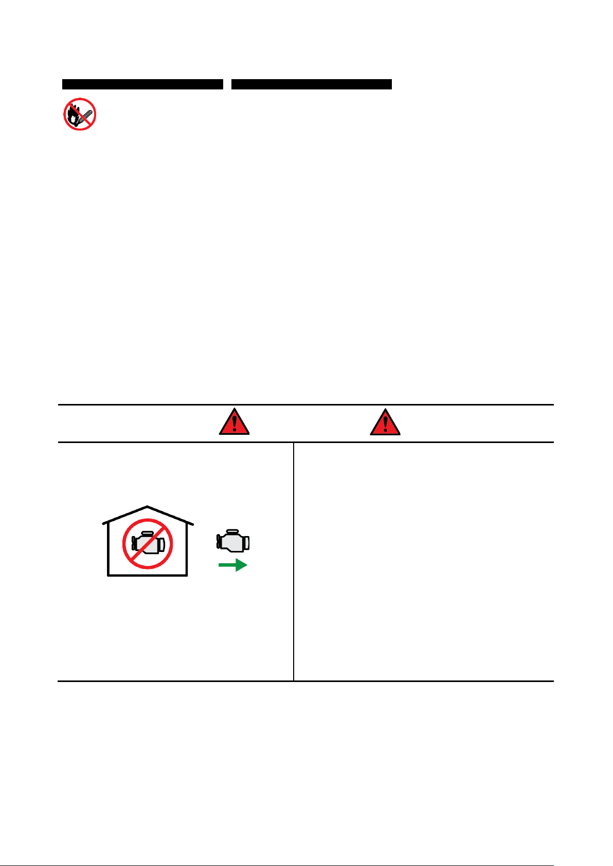
DANGER
Running combustion engines in confined areas
CAN KILL IN MINUTES. Engine exhaust fumes
contain carbon-monoxide – a deadly gas that you
cannot smell or see.
NEVER run a combustion engine in confined areas
EVEN IF windows and doors are open. ONLY run
petrol engines OUTDOORS and away from doors,
windows and vents.
Do not operate the equipment in hazardous locations,
such as where there may be a risk of fire or explosions
from flammable liquids, gases or dust.
Do not operate the equipment in confined areas where
exhaust gases, smoke or fumes could reach
dangerous concentrations.
Do not refuel a combustion engine while it is running,
on or hot.
Never smoke while refuelling combustion engines or
handling flammable substances.
For generators, the electrical output is potentially
lethal and must only be connected to a fixed electrical
installation by an appropriately licensed person.
Be aware that the equipment may include hazardous
components, such as blades, hot surfaces and moving
parts.
Handle any flammable substance with extreme
caution.
E&OE ©2018 Fuji Micro / Genforce / Bäumr-AG 3

Petrol Powered Inverter Generators
Table of Contents
Safety ................................................................................................................................................... 2
Applicable Models ............................................................................................................................. 6
Parts Identification ............................................................................................................................. 8
Before Use Checklist ......................................................................................................................... 9
Engine Oil .................................................................................................................................................. 9
Air Filter ...................................................................................................................................................... 9
Fuel ............................................................................................................................................................ 9
Priming the Fuel System.................................................................................................................... 10
Battery ...................................................................................................................................................... 10
Engine Starting ................................................................................................................................. 11
Manual/Pull Starting ................................................................................................................................. 11
Electric Starting ........................................................................................................................................ 12
Remote Starting ................................................................................................................................. 12
Stopping the Engine ................................................................................................................................. 12
Emergency Stop ................................................................................................................................ 13
Remote Stopping ............................................................................................................................... 13
Environmental Considerations ................................................................................................................. 13
Altitude............................................................................................................................................... 13
Temperature ...................................................................................................................................... 13
Operating the Generator ................................................................................................................. 14
Understanding Rated Output ................................................................................................................... 14
Calculating Generator Load ..................................................................................................................... 15
Control Panel and Functions .................................................................................................................... 16
Grounding the Generator ......................................................................................................................... 17
AC Applications ........................................................................................................................................ 17
DC Applications ....................................................................................................................................... 18
12VDC and 5VDC Devices ................................................................................................................ 18
Battery Charging ................................................................................................................................ 18
Maintenance ..................................................................................................................................... 19
Maintenance Schedule............................................................................................................................. 19
Checking and Changing Engine Oil ......................................................................................................... 20
Replacing the Battery ............................................................................................................................... 22
Battery/Fuse Removal/Installation ..................................................................................................... 22
Checking, Cleaning or Replacing the Air Filter ......................................................................................... 23
Air Filter Inspection and Cleaning ...................................................................................................... 23
Air Filter Removal/Installation ............................................................................................................ 23
Maintaining the Spark Plug ...................................................................................................................... 24
Spark Plug Cleaning and Gap Checking ........................................................................................... 24
E&OE ©2018 Fuji Micro / Genforce / Bäumr-AG 4

Petrol Powered Inverter Generators
Spark Plug Removal/Installation ........................................................................................................ 24
Transportation and Storage ............................................................................................................ 25
Troubleshooting ............................................................................................................................... 26
Specifications ................................................................................................................................... 28
Service and Maintenance Record .................................................................................................. 29
E&OE ©2018 Fuji Micro / Genforce / Bäumr-AG 5
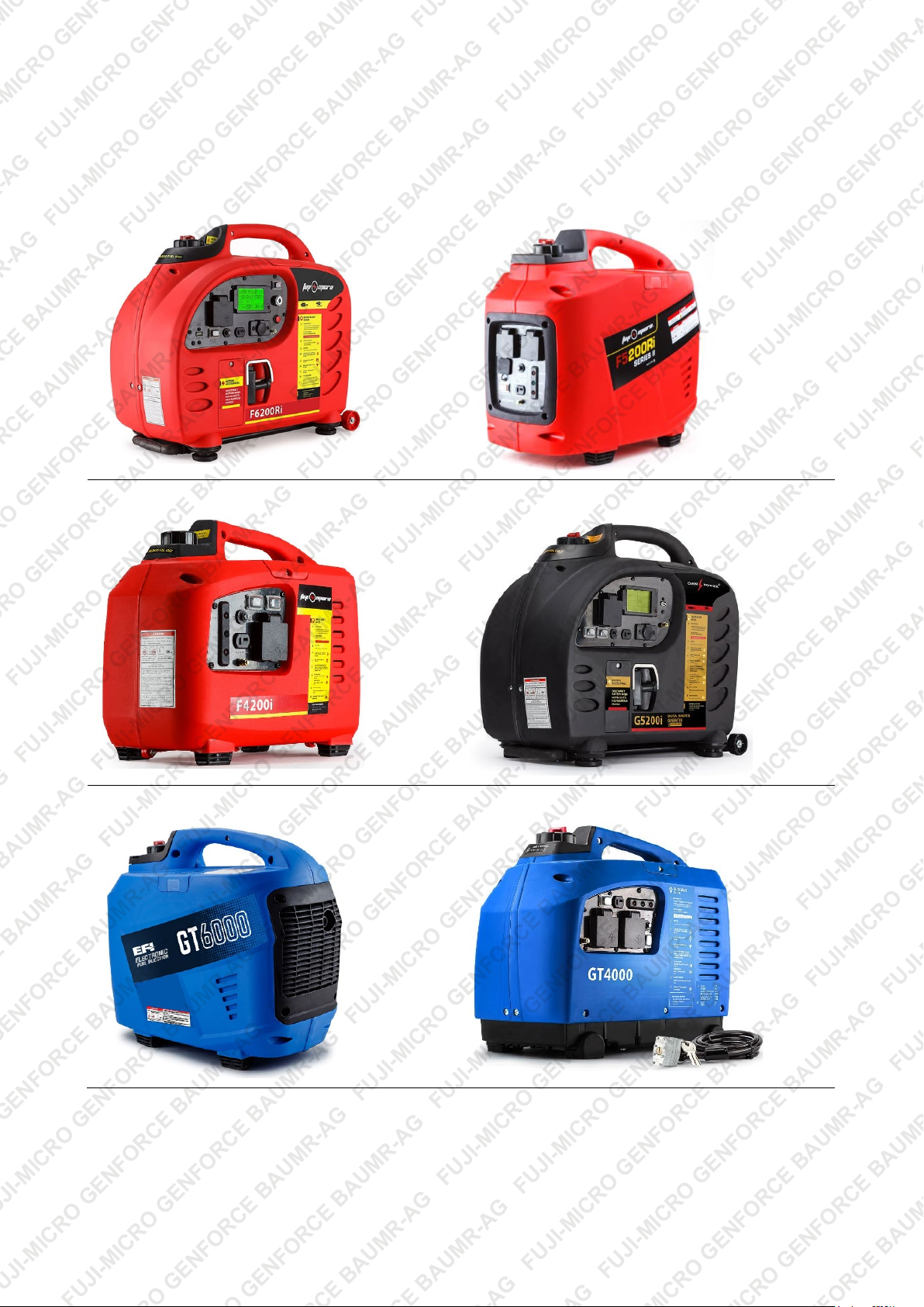
Petrol Powered Inverter Generators
Applicable Models
This manual applies to the following generators:
F6200Ri 165cc Fuel-Injected 3.2kW Electric Start
F4200Ri 105cc 2.5kW
F5200Ri 150cc Fuel-Injected 3.2kW
G5200i 125cc 2.5kW Electric Start
GT6000 150cc Fuel-Injected 3.2kW
GT4000 105cc 2.5kW
E&OE ©2018 Fuji Micro / Genforce / Bäumr-AG 6

Petrol Powered Inverter Generators
GT3000 53cc 1.7kW
BM-700i 150cc 3.2kW
E&OE ©2018 Fuji Micro / Genforce / Bäumr-AG 7
Petrol Powered Inverter Generators
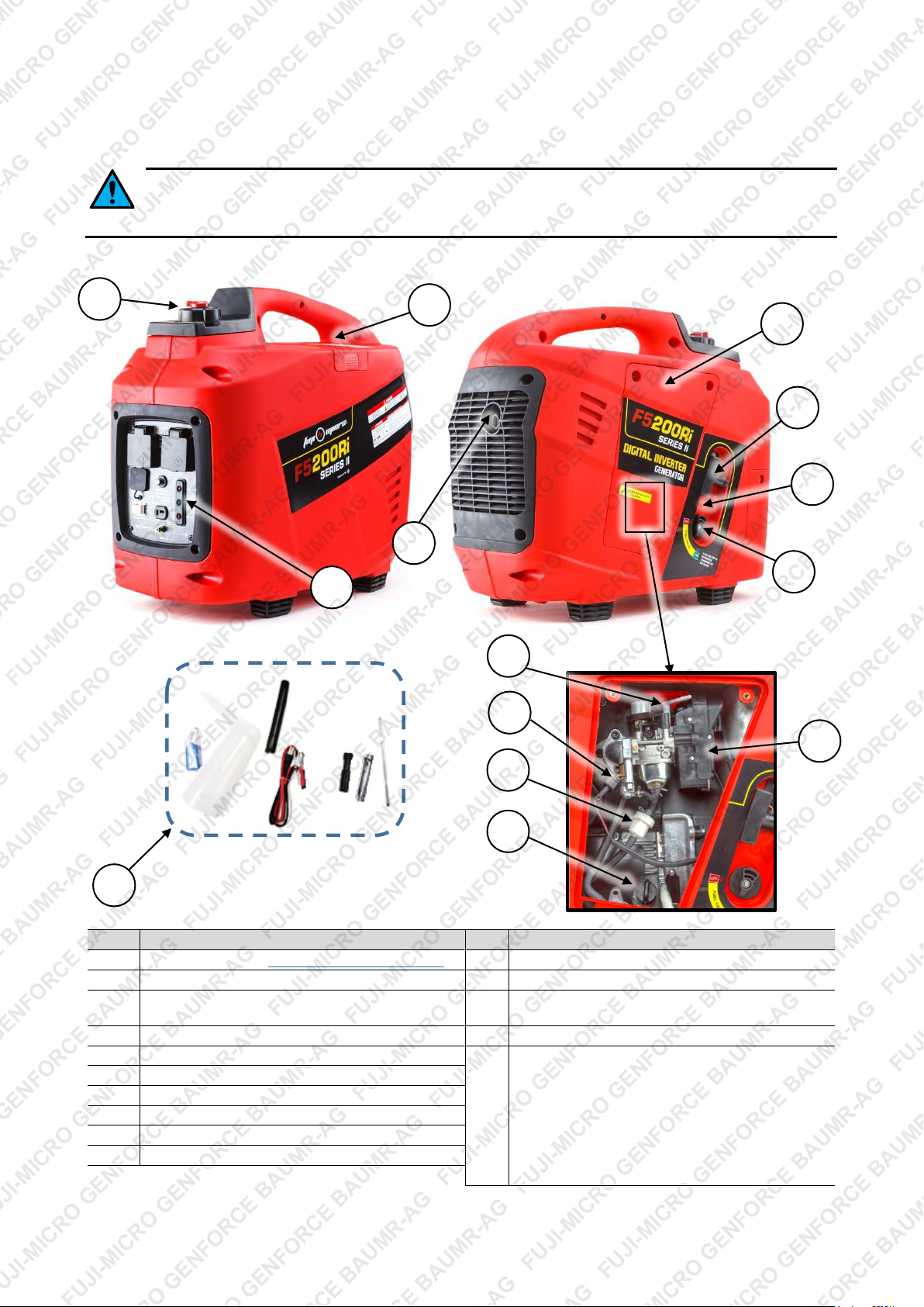
No.
Name
No.
Name
1
Control Panel (see Control Panel and Functions)
11
Air Filter Assembly (filter inside)
2
Fuel Filler
12
Fuel Injector
3
Exhaust
13
Choke (on non-fuel-injected models, the choke is
4
Spark Plug Access Cover (spark plug inside)
14
Primer (non-fuel-injected models only)
5
Carry Handle
15
Accessories / Tools (not all models may include
6
Engine Access Cover
7
Starter Cord
8
Fuel Tap (fuel strainer inside)
9
Oil Filler/Dipstick
10
Fuel Filter
1
3
6 7 8
11
10 9 13
14
Parts Identification
Products detailed in this manual may vary in appearance, inclusions, description and packaging
from those shown or described. This section shows typical major components common to most
petrol powered generators, the position of some components may also vary between models.
2
4
12
15
accessible through the engine access cover)
all or any accessories):
Oil Fill Bottle
Oil Drain Tube
12VDC Battery Charging Cable
Spark Plug Spanner
Screwdriver
Spark Plug (spare)
E&OE ©2018 Fuji Micro / Genforce / Bäumr-AG 8
Petrol Powered Inverter Generators
Video Tutorial:
Before Use Checklist
Ensure that you carry out all procedures below before
starting the engine or operating the equipment. All
procedures described are generic in nature and slight variations between
different models may exist. Failure to follow the checklist and carry out the procedures correctly may
result in making the product warranty void. The product is NOT supplied with engine oil, although traces
of oil from the manufacturing process may be present. It is essential to add adequate engine oil of the correct
type to the engine before use – see Checking and Changing Engine Oil. Failure to add engine oil will void
the product warranty.
Engine Oil
Four-stroke engines require engine oil in the crankcase for lubrication of internal components. Severe or
irreparable damage may occur if the engine is allowed to run without engine oil. The engine oil level requires
regular maintenance. Check the engine oil level and ensure that the oil level is at or just under the maximum
level indicator.
Some machines may feature an oil level sensor that will prevent the engine being started or automatically
stop the engine if the oil level falls below an acceptable level. This system, however, is not to be solely relied
upon. Always check that the engine oil level is at or near the "MAX" indicator before starting the
engine. See Checking and Changing Engine Oil.
Inverter Generator Set-Up
Air Filter
The air filter is used to prevent dirt and other particles from possibly entering the engine and causing internal
damage to it. The air filter requires regular maintenance.
Always check the air filter before starting the engine. See Checking, Cleaning and Replacing the Air Filter.
Fuel
Petrol/fuel/gasoline is extremely flammable – keep clear of naked flames or other ignition
sources. • The engine must be cool before refuelling.
Adequately fill the fuel tank with the correct fuel type.
• Use non-ethanol unleaded petrol (higher RON values will provide best engine performance). Do not use
old or contaminated fuel.
To fill or top up fuel:
1. Place the machine in an upright position on a flat and level surface.
2. Clean the machine around the fuel filler so that no dirt or other material enters the tank when the cap is
removed.
3. Remove (rotate left) the fuel filler cap.
4. Using a funnel, carefully fill the tank with fuel. Do not fill above the top of the strainer (if equipped) or
otherwise overfill the tank.
5. When finished, reinstall (rotate right) the fuel filler cap until firm. Wipe away any residual fuel from the
machine. If fuel has been spilt, move the machine away from the spillage before starting the engine.
E&OE ©2018 Fuji Micro / Genforce / Bäumr-AG 9

Petrol Powered Inverter Generators
A B C
Priming the Fuel System
For engines equipped with a fuel primer, it may be necessary to “prime” the fuel system
when first used or after running out of fuel before attempting to start the engine. This
means removing any air from the fuel line and filling the carburettor with fuel. To prime:
1. Fill the fuel tank with fuel.
2. Locate the fuel primer (A). The primer is a "rubber button" that acts as a pump
when pushed and released. it is generally located on the same side of the unit as
the fuel tap.
3. Press the fuel primer repeatedly until you feel that fuel is in the primer.
Battery
For electric start and remote control models, the battery is shipped with the unit, but must be connected in
order for electric starting and remote control functions to be available.
To connect the battery:
1. Use a screwdriver to remove the battery access cover (A) from the side of the unit. Once removed, the
battery and battery cables are accessible.
2. Carefully pull the battery connection cables (B and C) from the compartment and connect them.
3. Carefully tuck the cables back into the compartment, then re-install the battery access cover.
A
E&OE ©2018 Fuji Micro / Genforce / Bäumr-AG 10

Petrol Powered Inverter Generators
A B C
D
E
F
EE
Engine Starting
Before starting the engine, ensure that you have followed all procedures described in the
Before Use Checklist. The product is NOT supplied with engine oil, although traces of oil
from the manufacturing process may be present. It is essential to add adequate engine oil of the correct type
to the engine before use – see Checking and Changing Engine Oil. Failure to add engine oil will void the
product warranty. • Before starting the generator, disconnect all output sockets so that no load is
immediately placed on the generator as it starts up.
Different models may feature variations in design; for example, some have different engine types, electric
start etc. The following procedures and images are typical to all models, however, the position or appearance
of controls etc may vary. All major engine controls are identified on the machine by way of stickers or other
markings.
Once the engine is started, the engine speed will automatically regulate depending on connected load. For
example, under high loads, the engine will run at higher speed to maintain the required output.
Manual/Pull Starting
1. PRIME – If necessary, "prime" the fuel system.
2. FUEL – Place the fuel tap (A) in the "ON" position and the fuel filler cap vent (B) in the "ON" position.
3. CHOKE – If the engine is cold, use the choke.
4. IGNITION – Place the engine ON/OFF switch (C) in the "ON" ("I”") position. For key switches (if
equipped), insert the key then turn it one position to the right – this is the "ON" position
5. START – Slowly pull out the starter cord (D) until you feel it engage with the engine, then pull it out
rapidly. Hold the generator handle firmly when pulling the starter cord to prevent the machine toppling
over. The engine should start. Allow the starter cord to rewind slowly – do not let it "snap" back.
If the engine does not start, repeat step 3. If the engine fails to start after several attempts, refer to
Troubleshooting.
Using the Choke
In cold conditions or if the normal starting procedure is not
working, choke may be required to help start the engine:
1. For fuel-injected models, use a screwdriver to remove the
engine access cover (E). For non-fuel-injected models the
choke is accessible through the engine access cover (EE).
2. Move the choke lever (F) to the "COLD" or "START" position.
3. Start the engine as normal. As the engine warms up, slowly
move the choke lever to the "HOT" or "RUN" position.
4. For fuel-injected units, re-install the engine access cover.
If the engine cannot be started, check the engine oil level
before any other troubleshooting as the low oil safety
mechanism may be preventing the engine from starting.
E&OE ©2018 Fuji Micro / Genforce / Bäumr-AG 11

Petrol Powered Inverter Generators
A
B
C D B A C
F
Electric Starting
For models equipped with an electric start option, connect the battery before attempting to start the unit.
Using the electric start is the preferred starting method. If the battery is flat, use the manual/pull
starting method.
1. Follow steps 1 to 4 as per manual/pull starting.
2. START – Turn the ignition key fully to the right to, to the "START" position, to engage the starter motor.
The engine should start.
If the engine does not start, repeat step 2. If the engine fails to start after several attempts, refer to
Troubleshooting.
Remote Starting
The remote electric start feature is not recommended for use if the ambient
temperature is low enough to require choke for engine starting. • The
battery will be drained if the ignition remains in the "ON" position for extended
periods without the engine running.
For models equipped with remote control, to use remote engine start:
1. PRIME – If necessary, "prime" the fuel system.
2. FUEL – Place the fuel tap (A) in the "ON" position and the fuel filler cap vent (B)
in the "ON" position.
3. IGNITION – Place the engine ON/OFF key switch (if equipped) in the "ON" ("I") position. For key
switches, insert the key then turn it one position to the right – this is the "ON" position.
4. REMOTE OPERATION – Place the remote control switch (D) (if equipped) in the "ON" ("I") position.
5. START – Press (F) on the remote control to engage the starter motor. The engine should start.
If the engine does not start, repeat step 5 onward. If the engine fails to start after several attempts, refer to
Troubleshooting.
Stopping the Engine
1. OUTPUTS – Turn OFF any connected devices, then unplug them from the generator.
2. IGNITION – Place the engine ON/OFF switch or key switch in the "OFF" ("O") position.
3. FUEL – Place the fuel tap in the "OFF" position and the fuel filler cap vent in the "OFF" position.
E&OE ©2018 Fuji Micro / Genforce / Bäumr-AG 12

Petrol Powered Inverter Generators
A
Emergency Stop
Some models may feature an "emergency stop" button on the control panel. Press and hold
the button until the engine stops completely.
After using the emergency engine stop, it is recommended to follow the normal engine stop
procedure (disconnect connected devices and ignition and fuel OFF).
Remote Stopping
For models equipped with remote control, to use remote engine stop:
1. OUTPUTS – Turn OFF any connected devices.
2. STOP – Press (A) on the remote control to stop the engine.
After using the remote engine stop, it is recommended to follow the normal engine
stop procedure (disconnect connected devices and ignition and fuel OFF).
Environmental Considerations
Altitude
If the engine is being used in altitudes at or above 1500m (approximately 5000'), adjustments to the
carburettor may be required. This is because there is less oxygen in the air as altitude increases, which
effectively "enriches" the ratio of fuel to air going into the engine and the higher the altitude, the richer the
fuel mixture becomes. If the engine is being permanently operated at high altitude, it is recommended to
have an authorized service centre make the necessary carburettor adjustments. If the engine is used
occasionally at altitude (not extreme altitudes), no adjustments should be required, however, a slight
decrease in engine performance can be expected.
Temperature
If the engine is being used in extremely cold or hot
environments; for example, desert or snow conditions, the
type of engine oil may need to be changed to suit
environmental temperatures. Oil thickens as the temperature
decreases and thins as temperature increases, which means
that if the engine oil is not suited to the temperature its ability
to properly lubricate the engine may be affected. Use the
following chart to determine the correct engine oil:
E&OE ©2018 Fuji Micro / Genforce / Bäumr-AG 13

Petrol Powered Inverter Generators
25
30
35
40
45
Altitude (m)
Power Output Coefficient
0 1 0.98
0.96
0.93
0.90
500
0.93
0.91
0.89
0.87
0.84
1000
0.87
0.85
0.82
0.80
0.78
2000
0.75
0.76
0.71
0.69
0.66
3000
0.64
0.62
0.6
0.58
0.56
4000
0.54
0.52
0.5
0.48
0.46
Operating the Generator
Allowing the generator to run when being overloaded may permanently damage it
and/or shorten its service life and may void product warranty. • Ensure that the
generator is grounded (earthed) before using it. • Ensure that any device to be powered by the generator is
switched OFF before connecting it to the generator. • Ensure that all devices that will be powered by the
generator are electrically safe and functioning normally. If at any time a connected device appears to
malfunction, stop or slow down etc, immediately switch the generator and device OFF and disconnect the
device. • Do not exceed the rated power output of the generator. Consider the power rating for all connected
devices that will be running simultaneously, both AC and DC, and ensure that the sum of all power
consumption is no more than the generator rated output with consideration given to actual power output
based on altitude and temperature (see Understanding the Rated Output). For example, 2 x 1200W devices
will be acceptable for a 2.5kW rated output generator, however, will overload a 2kW unit. • Do not exceed the
rated current for the output socket. For example, do not connect a device that draws 15A to a 10A socket. • If
using an extension cable, ensure it is an approved type and has a minimum wire gauge of 1.5mm² up to a
cable length of 60m; 2.5mm² up to a cable length of 100m. • For appliances that place high "inductive" loads
when being started or stopped (for example, electric motors), consideration should be given to the rated
output of the generator and the required inductive load capacity. Rated output equates to approximately 45
to 75% of inductive load capacity. • Do not connect devices in parallel to the generator. • Devices sensitive to
input voltage fluctuation should be connected via a suitable surge protector.
Understanding Rated Output
The "rated output" is described as the maximum power that the generator can consistently and reliably
provide. The rated output of a generator is based around several factors including altitude, ambient
temperature and relative humidity. The specified rated output is calculated at an altitude of 0m, ambient
temperature of 25°C and relative humidity of 30%. Deviations from these values will affect the actual output
capacity of the generator. For example, if the generator is used at high altitude it will produce less power.
Basically, the higher the altitude, the warmer the ambient temperature and the greater the humidity, the less
power can be produced. The following table provides a guideline for calculating actual generator output
based on ambient temperature and altitude [note that humidity is ignored here as it has a marginal effect]:
Ambient Temperature (°C)
Examples:
•
At an approximate altitude of 1000m and 30°C ambient temperature, the power output coefficient is 0.85.
So, a rated output of 2.5kW becomes 2.5 x 0.85, which equates to an actual power output of 2.125kW.
•
At an approximate altitude of 2000m and 25°C ambient temperature, the power output coefficient is 0.75.
So, a rated output of 2.0kW becomes 2.0 x 0.75, which equates to an actual power output of 1.5kW.
•
At an approximate altitude of 3000m and 40°C ambient temperature, the power output coefficient is 0.58.
So, a rated output of 2.0kW becomes 2.0 x 0.58, which equates to an actual power output of 1.16kW.
E&OE ©2018 Fuji Micro / Genforce / Bäumr-AG 14

Petrol Powered Inverter Generators
Lamp
Radio
Television
Computer
Laptop
Oven
Slow Cooker
Blender
Power Tool
Electric Fan
Deep Fryer
Lamp
Iron
Music Player
(small)
Toaster
Cleaner
Video Player
Machine
Water Heater
Water Pump
Maker
Hair Dryer
Video Game
Calculating Generator Load
Most electrical devices clearly state the required power, usually in Watts (W). This information is generally
labelled on the device, or listed in its user manual. If a device lists power consumption figures in amperes (A)
only, calculate the wattage by multiplying the ampere rating by the voltage. For example, a 10A device @
240VAC equates to 2400W (10A x 240V). The sum of all devices required to be operating simultaneously
needs to equal or be less than the rated output of the generator.
Many devices require a different load on start-up/shut-down that is often much higher than the actual
continuous running requirements. For example, a water pump may require 2000W to start, and once started,
requires 500W to continue running. When calculating generator load, the start-up requirements need to be
factored in. If the start-up power consumption is not known, the table below lists typical consumption figures
for several device types that may assist in determining how many or which devices may be connected and a
starting order [that is, start the high consumption devices first, followed by devices with no additional start-up
power requirements].
Start-up Watts 50 to 150 100 to 200 150 to 500 800 200 1400
Running Watts 50 to 150 100 to 200 150 to 500 800 200 1400
Start-up Watts 250 850 1000 to 1500 600 800 to 2000 N/A
Running Watts 250 400 400 to 600 200 600 As Stated
Start-up Watts N/A N/A 800 to 2000 600 750 to 1800 N/A
Running Watts 1200 30 600 200 600 to 1500 50
Incandescent
Washing
Food
Refrigerator
Coffee
Vacuum
Microwave
Fluorescent
Start-up Watts 3400 N/A 2500 to 5000 600 to 1500 N/A N/A
Running Watts 1150 3000 to 4500 500 to 1000 600 to 1500 300 to 1200 20
Example (using the typical values above):
•
To run a radio, electric fan and small refrigerator requires an approximate running power consumption of
100W (radio) + 200W (fan) + 600W (refrigerator) = 0.9kW. However, when factoring in start-up power
requirements, the equation becomes 100W (radio) + 600W (fan) + 1500W (refrigerator) = 2.2kW.
Many generators have a "maximu m" output above that of the rated output, which is allowable for a
short period. This is to allow (up to a point) for increased start-up loads that reduce once connected
devices are running. Using the above example, a generator with a rated output of 1.5kW and ma xi mum
output of 2.2kW would be suitable.
E&OE ©2018 Fuji Micro / Genforce / Bäumr-AG 15

Petrol Powered Inverter Generators
2
7
1
1
8 5 3
10 9 13 6 14
5 3 4
10 9 11
12 2 6
Control Panel and Functions
The generator features a control panel for connecting devices and monitor or understand generator status.
The features vary between models; for example, some models have digital displays, several AC connections,
USB connection etc. The main features of each control panel type are described below.
No. Description
1 Engine ON / OFF – Place in the "ON" ("I") position to be able to start the generator. Place in the "OFF" ("O")
position to stop the generator.
2 240VAC Output – Used for powering a 240VAC device that connects via a standard 3-pin plug. The
generator may feature more than one socket. Lift the cover to access the connector.
3 12VDC Battery Charger Output – Used for charging a 12V battery (charging cable supplied).
4 12VDC Output – Used for powering a 12VDC device that connects via a standard vehicle 12V/cigarette
lighter adaptor (cable may be supplied). Lift the cover to access the connector.
5 12VDC Output Protection Reset – Used to reset the 12VDC output over-current protection. If the over-
current protection trips, the button “pops out”. Press to re-activate the generator DC output.
6 5VDC Output – Used for powering a 5VDC device that connects via a standard "USB" cable (cable may be
supplied). Lift the cover to access the connector (if applicable).
7 Economy Mode – Used to lower the engine idle speed when powering low-draw devices (for example, a
laptop or charging a battery) and conserve fuel. The generator automatically adjusts the engine speed based
on load, as normal.
8 Emergency Stop – Used to stop the engine instead of using the engine ON/OFF switch. Press and hold until
the engine stops.
9 Ground Connection – Uses to ground the generator – see Grounding the Generator.
10 Low Oil – Illuminates red if the engine oil level is inadequate and will automatically stop the engine. This
safety feature may also prevent the engine being started. If the engine oil level is low, top it up
11 Overload – Illuminates red when the power being drawn from the generator exceeds its rated power output
or a short-circuit has occurred in a connected device. If it remains illuminated, switch the generator OFF and
disconnect one or more devices before using the generator again. Ensure that the generator is operating
within its rated power output capacity or, in the event of a device short-circuit, have the device repaired. If this
indicator remains illuminated after generator start-up or without any devices connected to the generator,
switch the generator OFF and have it inspected at an authorized service centre.
12 Power – Illuminates green when the generator is operating normally and the power being drawn from it is
within its rated power output capacity.
.
E&OE ©2018 Fuji Micro / Genforce / Bäumr-AG 16

Petrol Powered Inverter Generators
A
No. Description
13 LCD – Provides generator information:
U – Shows the AC voltage (V) being generated. If the generator is overloaded, this is blank.
I – Shows the current (A) being drawn by connected devices. If the generator is overloaded, this is blank.
F – Shows the voltage frequency (Hz) being generated. If the generator is overloaded, this is blank.
P – Shows the power (W) being drawn by connected devices. If the generator is overloaded, this shows
"OVER W".
Oil – Shows "OK" if the oil level is adequate; if not, this is blank and the low oil indicator illuminates.
Time – Shows the length of the time that the generator has been running. This resets to zero when the
generator is stopped
Grounding the Generator
The generator must be properly grounded
before use. Failure to ground the generator
may create a shock or electrocution hazard.
Connect a length of insulated heavy gauge wire (C)
between the generator Ground connector (A) (on the
control panel) and a suitable ground point. You can create
a ground point by driving a metal rod (B) into the ground
and connecting the free end of the cable to it.
C
B
AC Applications
Observe the following safety precautions when powering 240VAC devices:
• Connect only devices that have power requirements compatible with the generator. •
Connect only devices that have connectors compatible with the generator output sockets. • Always switch
the connected device OFF before connecting to or disconnecting from the generator. • Do not connect
devices in parallel to the generator. • Devices sensitive to input voltage fluctuation should be connected via a
suitable surge protector.
1. Start the generator.
2. Ensure that any device to be connected is switched OFF, then plug the
device in to the applicable generator 240VAC outlet.
3. Switch the connected device ON and operate as normal.
4. When finished using the device, switch it OFF, then unplug the device from
the generator.
E&OE ©2018 Fuji Micro / Genforce / Bäumr-AG 17

Petrol Powered Inverter Generators
D
E
DC Applications
Observe the following safety precautions when powering low voltage DC devices and
charging batteries:
• When connecting a battery to the DC output, ENSURE that the polarity (+ to + and – to –) of connections is
correct. Failure to do so may represent an explosion hazard and/or damage the generator and/or connected
battery. • The DC circuit is not monitored and does not automatically switch off or self-regulate depending on
the voltage of the connected battery. This means that you must independently monitor battery charge status
and disconnect the battery before it is over-charged. Over-charging batteries may present an explosion
hazard. • The DC output over-current protection can be tripped in the event of too much current being drawn
(see Specifications for maximum current draw for differing generator models). If this occurs, the DC
protection reset switch (on the control panel) will "pop out". Press the switch to reset the protection and reactivate the generator DC output. • To prevent sparking near the generator, when disconnecting a battery,
disconnect the battery charging cable from the battery terminals before unplugging it from the generator DC
output socket. Disconnect the negative (-) terminal first, followed by disconnecting the positive (+) terminal
and do not allow the cable ends to touch. • When charging a battery that is mounted in a vehicle, at the
vehicle battery, disconnect the negative (-) terminal first, followed by disconnecting the positive (+) terminal.
Then, proceed to connect the battery charging cable as normal. Ensure that the battery terminals or charging
cable terminals do not make contact with the vehicle chassis as sparking may occur. • Do not attempt to start
a vehicle whilst its battery is connected to the generator, as damage to the generator may result. • Batteries
that are being charged may emit dangerous gases. Batteries being charged should be in a well ventilated
area and a safe distance from any sources of flame, heat, flammable or volatile materials. • Batteries contain
sulphuric acid. Contact with skin or eyes may cause burns – wash with water immediately (at least 15
minutes if has contacted eyes) and seek professional medical attention. Wear protective clothing and face
mask when handling batteries. • If battery acid is swallowed, administer water or milk and immediately seek
professional medical attention. • All batteries should be kept out of reach of children.
12VDC and 5VDC Devices
Some generators feature a protected 12VDC and or 5VDC
"USB" outlets that are used for powering suitable devices.
The 5VDC is "pure sine wave", allowing it to be used with
"sensitive" devices, such as laptop computers etc.
1. Start the generator.
2. Ensure that any device to be connected is switched
OFF, then plug the device/adapter in to the generator
12VDC outlet (A) (if applicable), or 5VDC USB connector (B) (if applicable), as required.
3. Switch the connected device ON and operate as normal.
4. When finished using the device, switch it OFF, then unplug the device from the generator.
A
Battery Charging
Some generators feature a protected 12VDC outlet
that is used for charging suitable batteries (vehicle
batteries etc). Use the supplied cable to connect
the battery to the generator.
1. Connect the battery charging cable (C) to the
generator DC output socket.
2. Connect the battery charging cable to the
battery terminals – red (D) to the battery
positive (+) terminal, black (E) to the battery
negative (-) terminal. Connect the positive (+) terminal first.
3. Start the generator.
4. When finished using the DC output, disconnect the battery charging cable from the battery, then
disconnect it from the generator.
C
B
E&OE ©2018 Fuji Micro / Genforce / Bäumr-AG 18

Petrol Powered Inverter Generators
Engine Oil
Check
Replace
Replace
as necessary
Air Cleaner
Check
Clean and replace as necessary
Spark Plug
Check
Replace
Adjust as
necessary
Combustion
Chamber
De-coke as
necessary
Check/tighten
as necessary
Flush and
Fuel Line
Replace as necessary
Fuel Filter
Clean and replace as necessary
Fuel Strainer
Check
Maintenance
Running combustion engines in confined areas CAN KILL IN MINUTES.
Engine exhaust fumes contain carbon-monoxide – a deadly gas that you
cannot smell or see. NEVER run a combustion engine in confined areas EVEN IF windows and doors are
open. ONLY run combustion engines OUTDOORS and away from doors, windows and vents. •
Petrol/fuel/gasoline is extremely flammable – keep clear of naked flames or other ignition sources. • The
product is NOT supplied with engine oil, although traces of oil from the manufacturing process may be
present. It is essential to add adequate engine oil of the correct type to the engine before use – see
Checking and Changing Engine Oil. Failure to add engine oil will void the product warranty. • Do not
have the engine running during inspection and maintenance unless specifically required. • The engine should
be cool enough to touch before performing maintenance activities. • Some maintenance activities described
may be beyond the scope of some users. For procedures that you are not comfortable with or have the tools
or experience for, have the unit serviced by a service centre or qualified technician.
To keep the machine performing at optimal efficiency, regular checks and maintenance is required. Proper
care and maintenance ensures best performance and longest service life.
The maintenance schedule below specifies preventative maintenance checks and necessary maintenance
tasks and how often they should be performed. The schedule applies to multiple engines; some engines may
not include some components, so maintenance on those components is not applicable.
Harsh operating environments such as extreme temperatures, dust etc may necessitate more
frequent maintenance. • Maintenance frequencies are based on general factors including a
maximum use of approximately 300 hours per year. Apply common-sense when following the maintenance
schedule based on your actual use of the product. • Keep reasonable records of maintenance activities for
reference. Failure to follow the maintenance schedule, using incorrect or non-compatible accessories
or replacements parts, or general negligence may result in making the product warranty void.
Maintenance Schedule
Frequency – Whichever Comes First
First Month or
Component/Task Every Use
Oil Leaks
Valve Clearance
Fasteners
Check/repair
20 Hours Use
Every 3 Months
or 50 Hours Use
Every 6 Months
or
100 Hours Use
Every Year or
300 Hours
Use
Fuel Tank
E&OE ©2018 Fuji Micro / Genforce / Bäumr-AG 19
clean

Petrol Powered Inverter Generators
B
A C X
Checking and Changing Engine Oil
The product is NOT supplied with engine oil, although traces of oil from the manufacturing
process may be present. It is essential to add adequate engine oil of the correct type to the
engine before use. Failure to add engine oil will void the product warranty. • Always check engine oil
level when the machine is in an upright position on a flat and level surface. • Do not use used or
contaminated engine oils. • Use only engine oils of the correct type (see Specifications). • Perform the first oil
change within the first 20 hours of use. Subsequently, change the oil every 20 hours of use. • It is
recommended that the engine be warm, but not hot, when performing oil changes. When the oil is warm it
drains faster. • Using dirty or incorrect engine oil may cause engine damage and void any warranty • Always
use suitable tools. • Always dispose of used oil in an environmentally responsible manner and according to
regulations. • Some engines feature oil level detection, which will prevent the engine being started or
automatically stop a running engine if there is insufficient oil. • Always check the oil level and ensure is at
or near the "MAX" indicator before using the machine.
Four-stroke engines require engine oil in the crankcase for lubrication of internal components. Severe or
irreparable damage may occur if the engine is allowed to run without engine oil. The engine oil level requires
regular maintenance as per the maintenance schedule.
To check engine oil level:
1. Place the machine in
an upright position on
a flat and level
surface.
2. Remove the 2 screws
(rotate left) securing
the engine access
cover (A), and remove
the cover.
3. Clean the machine around the oil filler cap (B) so that no dirt
or other material enters the engine when the cap is removed.
4. Remove the oil filler cap (rotate left) until fully unscrewed.
The oil level is determined by how far up the dipstick oil can
be seen. To check:
a. Wipe the dipstick (C) clean with a piece of cloth or
paper.
b. Insert the dipstick into the oil filler and screw it in.
c. Remove and inspect the dipstick – the MAX oil level
is approximately the top of the patterned section (X).
5. Ensure that the oil level is at or just under the permissible
maximum. If the oil level is low, add additional oil until the
correct level is reached. If the oil level is too high, drain some
oil until the correct level is reached.
6. When finished, reinstall (rotate right) the oil filler cap until firm. Wipe off any residual oil from the
machine.
7. Re-install the engine access cover and secure it with the 2 screws (rotate right).
E&OE ©2018 Fuji Micro / Genforce / Bäumr-AG 20

Petrol Powered Inverter Generators
D
E
To change the engine oil:
1. Place the machine on a suitable work surface that is flat and level
and have a container ready to catch drained oil.
2. Remove the 2 screws (rotate left) securing the engine access cover,
and remove the cover.
3. Clean the machine around the oil filler so that no dirt or other
material enters the engine when the cap is removed.
4. Unscrew (rotate left) and remove the oil filler.
5. Insert the supplied oil drain tube (D) to the oil filler hole and screw it
in (rotate right).
6. Tilt the machine and drain all oil from the engine. Once drained,
allow the machine to sit level again.
7. Fill the supplied oil fill bottle (E) with approximately 0.5l of engine oil,
then insert the nozzle into the oil filler and carefully add oil to the
engine until the permissible maximum is reached. Double- check
the oil level (described above).
8. When finished, re-install (rotate right) the oil filler cap until firm.
Wipe off any residual oil from the machine.
9. Re-install the engine access cover and secure it with the 2 screws (rotate right).
E&OE ©2018 Fuji Micro / Genforce / Bäumr-AG 21

Petrol Powered Inverter Generators
A
B E C D F
G
Replacing the Battery
Electric start models feature a 12V 5Ah battery for engine starting. The generator charges the battery during
normal operation, however, the battery will eventually fail and require replacement. The battery also has fuse
protection on the starter circuit. If the battery does not appear to be functional, check the fuse and replace if
blown, before replacing the battery.
Battery/Fuse Removal/Installation
To remove the fuse/battery:
1. Place the machine in an upright position on a flat and level surface.
2. Remove the screw (rotate left) securing the battery access cover (A), and remove the cover.
3. Carefully pull the battery connection cables (B) from the compartment and disconnect them.
4. On the battery cable, pull the cover from the fuse holder (C) and inspect the fuse (D). If the joining wire
(E) between the "spades" of the fuse is broken, the fuse is blown. Replace it with the same type, then
push the fuse holder cover back into position.
5. Unclip the rubber battery strap
(F) from the battery bracket (G).
6. Carefully pull the battery (H)
from the compartment.
7. Disconnect the battery cable (I)
from the battery terminals (J)
using a suitable spanner and
screwdriver.
To connect and re-install the battery:
8. Using a suitable spanner and screwdriver, connect the
battery cable to the terminals on the replacement
battery, ensuring that the red wire connects to the
positive (+) terminal and the black wire to the
negative (-) terminal.
9. Hold the battery strap, then gently slide the battery into
the compartment.
10. Connect the battery connection cables. Carefully tuck
the cables back into the compartment, then re-install
the battery access cover.
H
E&OE ©2018 Fuji Micro / Genforce / Bäumr-AG 22

Petrol Powered Inverter Generators
A E D
B
Checking, Cleaning or Replacing the Air Filter
Operating the machine without a functional air filter may cause severe engine damage and will void
any warranty. • A dirty or oil saturated air filter will restrict air flow, which can be mistaken as fuel
system problems. Check the condition of the air filter before adjusting engine idle speed, where applicable. •
If the air filter is damaged (torn, broken, disintegrating), replace it.
The air filter is used to prevent dirt and other particles from possibly entering the engine and causing internal
damage to it. The engine breather may be connected to the air intake assembly – this may lead to a build-up
of oil in the air filter over extended use and is normal. The air filter requires regular maintenance as per the
maintenance schedule.
Air Filter Inspection and Cleaning
Inspect the air filter for dirtiness and debris, damage etc. Clean or replace the filter element as necessary. To
clean air filters:
• For foam filters, wash the filter in warm water and mild detergent, then rinse and allow to dry.
• For paper filters, use compressed air to blow particles from it. The air should be blown from the engine
side of the filter.
• Clean all other air filter assembly components using water and mild detergent, then dry them.
• For foam filters, place a few drops of clean engine oil on the filter then squeeze it a few times to spread
the oil through the filter material and remove any excess oil.
Air Filter Removal/Installation
To remove the air filter:
1. Place the machine in an upright position on a flat and level surface.
2. Remove the 2 screws (rotate left) securing the engine access cover (A), and remove the cover.
3. Remove the 3 screws (E) (rotate left) securing the air filter cartridge (B) to the air intake assembly (C).
4. Pull the air filter cartridge out.
5. Unclip the plastic cage (D) on the air filter cartridge to remove the air filter element.
To install the air filter:
1. Insert the air filter cartridge into the air intake assembly and secure it with the 3 screws (rotate right). Do
not over-tighten.
2. Re-install the engine access cover and secure it with the 2 screws (rotate right).
E&OE ©2018 Fuji Micro / Genforce / Bäumr-AG 23

Petrol Powered Inverter Generators
A B B
X
C
A
B
C
Maintaining the Spark Plug
If the spark plug is damaged (cracked insulator, broken or eroded electrodes etc), replace it. •
Always use spark plugs of the correct "heat range" - see Specifications.
The spark plug is used to ignite the air/fuel mixture inside the engine. The spark plug has electrodes on one
end and an electrical terminal on the other. The spark plug requires regular maintenance.
Spark Plug Cleaning and Gap Checking
The spark plug should be checked and cleaned as per the maintenance schedule.
1. Remove any carbon deposits on the spark plug (A) electrodes (B) with a wire
brush.
2. Clean the spark plug threads and the electrical terminal (C) on the top.
To check and adjust the spark plug "gap":
1. Use "feeler" or "thickness" gauges (X) to measure the existing gap. The gauge
must drag a little when being slid between the electrodes (2) – this means the
measurement is fairly accurate.
2. Adjust the gap to within specification (see Specifications). If the gap needs to be
reduced, gently tap the electrode as required. If the gap needs to be increased,
use pliers to gently pull the electrode as required.
3. Measure the gap again and ensure it is within the specified range before re-installing the spark plug.
Spark Plug Removal/Installation
1. Lift and slide the spark plug access cover (A) from the generator.
2. Pull the electrical lead (B) from the terminal on top of the spark plug.
3. If accessible, clean the area around the spark plug so that no dirt or other material can enter the engine
when the spark plug is removed.
4. Use the spark plug socket (C) to remove the spark plug (rotate left).
To re-install the spark plug:
1. Place the spark plug in its hole and screw it in (rotate right) until "finger tight".
2. Use the spark plug socket to tighten the spark plug approximately one quarter turn (do not over-tighten).
3. Place the electrical lead over the spark plug terminal and push it down so that it connects firmly with the
terminal.
4. Re-install the spark plug access cover.
E&OE ©2018 Fuji Micro / Genforce / Bäumr-AG 24

Petrol Powered Inverter Generators
Transportation and Storage
Always ensure that the machine is cool enough to touch before transporting or
storing. • Petrol/fuel/gasoline is extremely flammable – keep clear of naked flames or
other ignition sources. • Always transport the machine with the fuel tap and engine ON/OFF switch in the
“OFF” position. • Drain the fuel tank before transportation or storage.
Preparing for Transport and Storage
• Drain the fuel system by allowing the engine to run until it stops.
• Ensure the fuel tap, engine ON/OFF switch (or key switch, if applicable) and fuel cap vent are in the
"OFF" position.
• Avoid exposing the equipment to direct sunlight, particularly during transportation.
• Ensure the equipment is secure and upright during transport.
• Store the unit in a dry, well-ventilated area and out of the reach of children.
Long Term Storage
5. Follow the normal procedures for storage, then:
• Drain the fuel system. It is advised to have the fuel tank as empty as possible before draining.
a. Unscrew (rotate left) the carburettor drain plug. Use a suitable container to catch the draining fuel,
and allow the fuel to drain. Store the drained fuel in a properly sealed container.
b. Re-install (rotate right) the carburettor drain plug and tighten.
6. Remove the spark plug and put 30ml of clean engine oil into the cylinder. Pull the starter rope slowly to
distribute the oil. Re-install the spark plug.
7. Cover the equipment.
E&OE ©2018 Fuji Micro / Genforce / Bäumr-AG 25

Petrol Powered Inverter Generators
Troubleshooting
Running combustion engines in confined areas CAN KILL IN MINUTES. Engine
exhaust fumes contain carbon-monoxide – a deadly gas that you cannot smell or see.
NEVER run a combustion engine in confined areas EVEN IF windows and doors are open. ONLY run
combustion engines OUTDOORS and away from doors, windows and vents. • Petrol/fuel/gasoline is
extremely flammable – keep clear of naked flames or other ignition sources. The product is NOT supplied
with engine oil, although traces of oil from the manufacturing process may be present. It is essential to add
adequate engine oil of the correct type to the engine before use – see Checking and Changing Engine Oil.
Failure to add engine oil will void the product warranty. • Do not have the engine running during
inspection and maintenance unless specifically required. • The engine should be cool enough to touch before
performing maintenance activities. • Some maintenance activities described may be beyond the scope of
some users. For procedures that you are not comfortable with or have the tools or experience for, or if
problems persist after following all suggested actions, contact a service centre or qualified technician.
The following information may assist in identifying a problem and rectifying it.
Difficulty starting the engine.
Possible Fault Action
Lack of fuel Check that t here is fuel in the ta nk a nd the fuel tap is in the "ON" position. • To further
Engine "OFF" Ensure engine ON/OFF switch is in the "ON" position.
Not enough engine oil Check engine oil level and ensure it is at or just below the MAX indicator. After topping up,
Carbon build-up on spark plug Remove the spark plug and clean any carbon from the electrodes before re-installing it.
Spark plug faulty Remove the spark plug, then reconnect the plug lead to it. Place fuel tap in the "OFF"
Engine "flooded" with fuel Place the choke in "HOT" or "RUN" position. Leave the ON/OFF switch in the "OFF"
check if fuel is reaching the carburettor, remove the carburettor drain plug and check if fuel
drains.
shake the generator from side to side a little to distribute the oil.
position and the engine ON/OFF switch in "ON" position. Touch the spark plug electrode to
a part of the engine crankcase, away from the spark plug hole, and attempt to start the
engine – a spark should be visible across the electrodes as the engine is rotated. If no
spark is visible, replace the spark plug.
position. Pull the starter cord several times to assist clearing excess fuel from engine before
attempting to start engine.
Electric engine start not working.
Possible Fault Action
Battery fuse blown Check and replace fuse if required.
Battery no longer serviceable Replace battery.
Engine starts but does not idle.
Possible Fault Action
Blocked air filter Check and clean the air filter.
Idle speed requires adjustment Adjust idle speed until engine runs smoothly and at a reasonable speed when idling. For
E&OE ©2018 Fuji Micro / Genforce / Bäumr-AG 26
fuel-injected models, idle speed adjustment should not be required.

Petrol Powered Inverter Generators
Difficulty restarting the engine after use or engine stops suddenly during use.
Possible Fault Action
No fuel or engine oil Check fuel level and ensure adequate fuel is available. For some engines, an engine oil
Overheating Allow engine to cool before restarting. If possible, improve engine cooling, such as
Carbon build-up on spark plug Remove the spark plug and clean any carbon from the electrodes before re-installing it.
Carburettor blocked Clean the carburettor.
sensor will automatically switch off the engine or prevent starting if a low engine oil level is
detected.
operating in lower temperatures or in shade etc.
Reduced engine speed/power during use.
Possible Fault Action
Blocked air filter Check and clean air filter.
Carbon build-up in engine and/or
entry to exhaust silencer
Carbon build-up on spark plug Remove the spark plug and clean any carbon from the electrodes before re-installing it.
Carburettor blocked Clean the carburettor.
Remove the engine cylinder head and clean any carbon from the combustion chamber. For
the exhaust silencer, remove it and clean any carbon deposits from the exhaust port.
Generator runs, but connected devices are not receiving power.
Possible Fault Action
Generator overloaded Check if Overload indicator is illuminated (red). Stop the generator and disconnect all
devices. Start the generator and check that Overload indicator is not lit and that the Power
indicator is illuminated green. Connect a device and check that it is being powered properly,
if not contact an authorized service centre.
Generator runs and AC outputs OK, but no DC output.
Possible Fault Action
DC output over-current protection
switch tripped
Reset DC over-current protection switch.
E&OE ©2018 Fuji Micro / Genforce / Bäumr-AG 27

Petrol Powered Inverter Generators
Specifications
165cc Engines
Engine Type 4-stroke, single cylinder
Fuel Type Non-ethanol unleaded petrol (higher RON values provide best performance)
Spark Plug Type A7RTC
Spark Plug Gap 0.7 to 0.8mm (0.028 to 0.032")
Valve Clearance Inlet: 0.08mm ± 0.10mm (0.003" ± 0.001")
Exhaust: 0.1mm ± 0.12mm (0.004" ± 0.005")
Oil Type SAE 10W-30 automotive engine oil recommended for general use
Oil Capacity Approximately 0.45l (always check level)
150cc Engines
Engine Type 4-stroke, single cylinder
Fuel Type Non-ethanol unleaded petrol (higher RON values provide best performance)
Spark Plug Type A7RTC
Spark Plug Gap 0.6 to 0.8mm (0.024 to 0.032")
Valve Clearance Inlet: 0.08mm ± 0.10mm (0.003" ± 0.001")
Exhaust: 0.1mm ± 0.12mm (0.004" ± 0.005")
Oil Type SAE 10W-30 automotive engine oil recommended for general use
Oil Capacity Approximately 0.35l (always check level)
105cc Engines
Engine Type 4-stroke, single cylinder
Fuel Type Non-ethanol unleaded petrol (higher RON values provide best performance)
Spark Plug Type A7RTC
Spark Plug Gap 0.6 to 0.8mm (0.024 to 0.032")
Valve Clearance
Oil Type SAE 10W-30 automotive engine oil recommended for general use
Oil Capacity Approximately 0.35l (always check level)
Inlet: 0.08mm ± 0.10mm (0.003" ± 0.001")
Exhaust: 0.1mm ± 0.12mm (0.004" ± 0.005")
53cc Engines
Engine Type 4-stroke, single cylinder
Fuel Type Non-ethanol unleaded petrol (higher RON values provide best performance)
Spark Plug Type F7RTC
Spark Plug Gap 0.6 to 0.8mm (0.024 to 0.032")
Valve Clearance Inlet: 0.08mm ± 0.10mm (0.003" ± 0.001")
Exhaust: 0.1mm ± 0.12mm (0.004" ± 0.005")
Oil Type SAE 10W-30 automotive engine oil recommended for general use
Oil Capacity Approximately 0.25l (always check level)
E&OE ©2018 Fuji Micro / Genforce / Bäumr-AG 28

Petrol Powered Inverter Generators
Date
Date
Date
Date
Date
Engine Oil
Plug
Filter
Replace Fuel
Lines
Clean Fuel
Tank
Check/Adjust
Clearance
De-coke
Date
Date
Date
Date
Date
Replace
Engine Oil
Plug
Replace Air
Filter
Filter
Lines
Clearance
Chamber
Service and Maintenance Record
Use the following tables as a record of machine servicing and maintenance. Keeping accurate records will
help ensure better machine service life and may simplify fault diagnosis and any possible warranty claims.
Place a tick in the required box for either clean or replace with the date, as required.
Replace
Replace Spark
Replace Air
Replace Fuel
Filter
Valve
Combustion
Chamber
Replace Spark
Replace Fuel
Replace Fuel
Clean Fuel
Tank
Check/Adjust
Valve
De-coke
Combustion
E&OE ©2018 Fuji Micro / Genforce / Bäumr-AG 29

Some experts believe the incorrect or prolonged use of almost any product could cause serious injury or
death. For information that may reduce your risk of serious injury or death, consult the points below and
additionally, the information available at www.datastreamserver.com/safety
• Consult all documentation, packaging and
product labelling before use. Note that
some products feature online
documentation which should be printed and
kept with the product.
• Check product for loose / broken / damaged
/ missing parts, wear or leaks (if applicable)
before each use. Never use a product with
loose / broken / damaged / missing parts,
wear or leaks (if applicable).
• Products must be inspected and serviced (if
applicable) by a qualified specialist every 6
months assuming average residential use
by a person of average weight and strength,
above average technical aptitude, on a
property matching average metropolitan
specification. Intended use outside these
guidelines could indicate the product is not
suitable for intended use or may require
more regular inspection or servicing.
• Ensure all possible users of the product
have completed an industry recognized
training course before being given access
to the product.
• The product has been supplied by a general merchandise
retailer that may not be familiar with your specific
application or your description of the application. Be sure
to attain third-party approval for your application from a
qualified specialist before use regardless of prior
assurances by the retailer or its representatives.
• This product is not intended for use where fail-safe
operation is required. As with any product (take an
automobile, aircraft, computer or ball point pen for
example), there is always a small chance of technical
issues that needs to be repaired or may require
replacement of the product or a part. If the possibility of
such failure and the associated time it takes to rectify
could in any situation inconvenience the user, business or
employee then the product is not suitable for your
requirements. This product is not for use where incorrect
operation or a failure of any kind, including but not limited
to a condition requiring product return, replacement,
service by a technician or replacement of parts could
cause a financial loss, loss of employee time or an
inconvenience requiring compensation.
• If this item has been purchased in error after considering
the points above, simply contact the retailer directly for
details of their returns policy, if required.
©2017 Fuji Micro / Genforce / Bäumr-AG. All rights reserved. No part of this document, including descriptive
content, concepts, ideas, diagrams or images may be reproduced or transmitted in any form or by any
means, electronic or mechanical, including photocopying, scanning or recording, or any information storage
and retrieval system, without express permission or consent from the publisher.
E&OE ©2018 Fuji Micro / Genforce / Bäumr-AG
 Loading...