

FUJI-IMVAC BT-50 Operator’s Manual
™
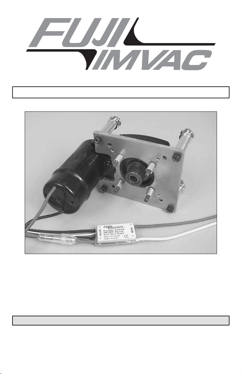
Instructions for the Fuji-Imvac Electric Starter BT-50
Manufactured by FUJI-IMVAC INC.
YOKOHAMA, 235-0005 JAPAN
Worldwide Distributor (except Japan): Hobbico®, Inc.
Champaign, IL 61826 USA
www.fuji-imvac.com
Fuji-Imvac is not related to the original Fuji Engines sold by Mecoa.
INTRODUCTION
These instructions explain the installation of the Electric Starter BT-50 on the
Fuji-Imvac BT50SA engine.
Entire Contents © Copyright 2009 FJIZ1150 for FJIG1150 V1.1

FUJI-IMVAC BT-50 ELECTRIC STARTER PARTS LIST
1
2
3
4
5
6
7
8
9
10
11
12
13
14
15
16
1. Electric starter case with motor
2. Tamiya connectors
3. Capacitors
4. 30A fuse
5. Fuse holder
6. Electrical wire
7. Aluminum firewall spacers
8. Electronic soft start module
9. Rubber cap
PARTS AND TOOLS REQUIRED FOR THE
INSTALLATION THE BT-50 ELECTRIC STARTER
6 to 10 cell, 1900mAh battery
·
(GPMP0740), (GPMP0741),
(GPMP0742), (GPMP0743)
Flexible pushrod (GPMQ3700)
·
30-min epoxy (GPMR6043)
·
Thin CA (GPMR6001)
·
Electric noise suppressant (see note
·
below)
10. Firewall mounting socket head
cap screws
11. Engine mounting bolts
12. Electric starter mounting bolts
13. Firewall blind nuts
14. Firewall washers
15. Engine mounting spacers
16. Aluminum Electric starter
mounting plate
Phillips screwdriver (HCAR1090)
·
Solder iron and soldering supplies
·
(HCAR0776)
Electric drill with 1/4" [6.4mm] drill bit
·
Great Planes® Pro™ Threadlocker
·
(GPMR6060)
Metric allen wrenches (HCAR0521)
·
Electrical tape
·

REPLACEMENT PARTS
To order replacement parts for the Fuji-Imvac BT-50, use the following order
numbers. Replacement parts are available only as listed. Replacement parts are
not available from Product Support, but can be purchased from hobby shops or
mail order/Internet order firms. If you need assistance locating a dealer to purchase
parts, visit www.greatplanes.com and click on “Where to Buy.” If this electric starter
is missing parts, contact Product Support (see back cover).
(A) FJIG1201 ......................Starter Gear Case A
(B) FJIG1202 ......................Starter Gear Case B
(C) FJIG1203 ....................... Starter Motor Cover
(D) FJIG1204 ..................... Starter Motor Spacer
(E) FJIG1205 ......................Starter Gear 2.3 to 1
(F) FJIG1206 ..................................Starter Motor
(G) FJIG1207 ................. Starter Gear Assembly
(H) FJIG1208 ......................0.5 Gear Shift Collar
(I) FJIG4720 ....................Starter Mounting Plate
(J) FJIG7171 ........................5x15 Beveled Head
Phillips Screws
(K) FJIG7172 ..............................4x10 Set Screw
(L) FJIG7173 ................... 4.5x12 Beveled Screw
(M) FJIG7174 ............. 4x30 Phillips Head Screw
With Washers
(N) FJIG3650 ..............................Starter Collar A
IMPORTANT NOTES
1. The electric starter depicted in this manual has a Battery Eliminator Circuit
(BEC). The BEC circuit is rated at 1 Amp. Do not use this circuit to power the
receiver of your airplane. The BEC cannot handle more than three regular sized
servos. If you do so the BEC will fail with possible catastrophic consequences for
your airplane. Turn off the micro switch on the electronic soft start module to
disconnect the BEC circuit.
2. In order to avoid interference from the gas engine, you must use an electric
noise suppressant on the electric starter’s wiring that comes back from the electric
motor. Radio Shack® offers two types of electrical noise suppressants. The
simplest noise suppressant is called “Snap Together Ferrite Choke” and its part
number is 273-105. The other type Radio Shack offers is the “10 Amp Noise
Filter”. Its part number is 27-051.
3. The starter’s remote On/Off switch should always be assigned to a spring-
loaded switch on your transmitter. It is important that you do this for safety
reasons. The spring loaded switch will always be in the “Off” position when the
transmitter is turned on and the starter motor will always stop spinning when you
release the switch after the engine is started.
 Loading...