

Page 1
Projector
Basic Manual
(Installation and Basic Operation)
BL00005017-202
Page 2

Table of Contents
Safety Precautions 1
For Your Safety ........................................................................................................................................................ 1
4 WARNINGS ....................................................................................................................................................................................................1
4 CAUTIONS .....................................................................................................................................................................................................2
Precautions for Storage and Use ...............................................................................................................................................................3
Safe Use of Lasers ...................................................................................................................................................4
4 WARNINGS ....................................................................................................................................................................................................4
4 CAUTION ........................................................................................................................................................................................................ 4
Notes on the Laser .............................................................................................................................................................................................4
Laser Warning Stickers ..................................................................................................................................................................................... 4
NOTICES 5
Caution: .....................................................................................................................................................................................................................5
FCC Warning: .........................................................................................................................................................................................................5
For Customers In Canada...............................................................................................................................................................................5
About the Icons ...................................................................................................................................................................................................6
Disposal of Electrical and Electronic Equipment in Private Households In the European Union, Norway,
Iceland and Liechtenstein: ............................................................................................................................................................................6
Introduction 7
Package Contents ................................................................................................................................................... 7
Parts of the Projector ............................................................................................................................................. 8
Installation 9
Choosing a Location...............................................................................................................................................9
Spacing .....................................................................................................................................................................................................................9
Installing the Projector in Vertical Orientation ..............................................................................................................................10
Using the Stands .............................................................................................................................................................................................. 10
Lens Shift Range and Projection Distance ....................................................................................................................................... 11
Basic Operation 15
The Control Panel .................................................................................................................................................15
On/Standby ...........................................................................................................................................................16
Turning the Projector On ............................................................................................................................................................................ 16
Switching to Standby .................................................................................................................................................................................... 16
Page 3

Table of Contents
Projector Settings 17
Rotating the Lens ................................................................................................................................................. 17
Focus ......................................................................................................................................................................19
Lens Shift ...............................................................................................................................................................20
Zoom ......................................................................................................................................................................21
Keystone Compensation .....................................................................................................................................22
Connections 23
Connecting HDMI Devices ...................................................................................................................................23
Connecting Third-Party Video Transmitters ......................................................................................................23
Technical Notes 24
Supported Resolutions ........................................................................................................................................24
HDMI/HDBaseT .................................................................................................................................................................................................24
The Remote Control .............................................................................................................................................25
Indicator Lamps ....................................................................................................................................................26
Regulatory 27
Safety .....................................................................................................................................................................27
Laser Safety ...........................................................................................................................................................27
Electro-Magnetic Compatibility .........................................................................................................................27
Emissions ..............................................................................................................................................................................................................27
Immunity .............................................................................................................................................................................................................. 27
Environmental ......................................................................................................................................................27
Marking .................................................................................................................................................................27
Federal Communications Commission (FCC) warning 28
Owner’s Manual
See the Owner’s Manual for more information.
https://optics.fuji lm.com/projector/en/spec/manual/fp-z5000/
iii
Page 4

Safety Precautions
4
WARNINGS
For Your Safety
The 4 WARNING and 4 CAUTION indications in this document indicate the following:
4 WARNINGS
4 CAUTIONS
This section lists important precautions that must be followed to ensure safe and correct use of the product.
Read them before using the product and observe them during use.
4
WARNINGS
• Be sure the product is installed securely. Serious accidents could result should the product fall from a height.
• Ceiling installations (where the product is suspended from the ceiling) should be performed only by professionals with the requisite skills. If installed incorrectly, the product could fall, potentially causing a serious
accident.
• When working in high places, work with a partner, use a safety line, and take all other precautions necessary
to ensure safety. Slipping, falling, or loss of balance could result in serious accidents.
• When installing the product in high places, ensure that people below keep their distance. Falling objects
could cause serious accidents.
• Do not install or use the product in a bath or shower. Failure to observe this precaution could result in re
or electric shock.
• Do not handle the product with wet hands. Failure to observe this precaution could result in electric shock.
• Do not modify, tug, or twist the connecting cables, subject them to excessive heat, or place them under
heavy objects. Damage to the cables could result in re or electric shock. Should the cables be damaged,
contact a Fuji lm-authorized service technician.
• Do not use cables if their connectors have ever been bent.
• Do not place the product on unstable surfaces. Be sure the product is level. Injury could result if the product
tips or falls.
• Do not touch the metal parts of the product during thunderstorms. Lightning strikes can produce induced
current that could cause electric shock.
• Do not place vessels containing water, chemicals, or other liquids on the product. Liquid that nds its way
into the product could cause re or electric shock.
• Never look directly into the lens while the product is on. The bright light could cause visual impairment or
other injury. Do not look into the lens with magnifying glasses, telescopes, or other optical instruments.
• Do not insert ammable material, metal, or other foreign objects into the product or leave them in its vicinity. Failure to observe this precaution could result in re, burns, or electric shock.
• Do not use sprays containing ammable gas to remove dust or other foreign matter from the lens. The gas
could ignite, causing re.
• Do not use the product in locations where the air may contain ammable or explosive gases. The gases
could ignite, causing re.
• Do not place ammable objects in front of the lens. Failure to observe this precaution could result in re.
Failure to observe warnings could result in death or serious injury.
Failure to observe cautions could result in injury or property damage.
1
Page 5

Safety Precautions
4
CAUTIONS
• Do not block the light from the product with books, cloths, or other objects. Objects placed in the beam
could become hot, potentially melting or causing burns or re. Light re ected from the objects could also
cause the lens to overheat, causing product malfunction.
• Do not touch the lens or metal parts of the product while it is on or immediately after it has been switched
to standby. Failure to observe this precaution could result in burns or other injury.
• Be careful not to drop the product when lifting it.
• Should you notice that the product is not functioning normally, switch it to standby and disconnect the
power and USB cables. Continuing to use the product when it is emitting smoke or unusual smells or otherwise functioning abnormally could result in re, electric shock, or visual impairment.
4
CAUTIONS
• Use the product only as described in this manual.
• The product and its accessories are precision devices. Under no circumstances should they be subjected to
excessive force.
• Be careful not to drop the product when lifting it to attach the stands.
• Attach the stands securely. When using the stands, be sure the legs are fully open. If the stands are not
securely attached or the legs are not fully open when the product is oriented vertically, the product could
become unbalanced and tip.
• Replace the lens cap if the product will not be used for an extended period.
• The lens includes moving parts: do not apply excessive force or subject the lens to physical shocks.
• Do not leave the product in locations where it will be exposed to soot, steam, or excessive humidity or dust.
Failure to observe this precaution could result in re or electric shock.
• Do not leave the product in locations where it will be exposed to high temperatures or direct sunlight. Failure to observe this precaution could result in re.
• Do not leave the product or, if the batteries are inserted, the remote control unattended in locations exposed to direct sunlight or high temperatures, for example directly in the path of warm air from a heater.
Excessive heat could deform the casing or damage the product’s internal parts, resulting in re.
• Do not place heavy objects on the product. The objects could become unbalanced and tip or fall, causing injury.
• Do not use the power cable if the plug is damaged or does not t securely into the socket. Failure to observe
this precaution could result in re or electric shock.
• Keep your face and hands, as well as objects that may be warped or otherwise damaged by heat, away
from the exhaust vent while the product is in use. The hot air from the vent could cause burns or deform or
damage the objects.
• For safety, be sure to unplug the product when it is not in use. Failure to observe this precaution could result
in re due to deterioration of the insulation or other causes.
• Before transporting or cleaning the product, switch it to standby, unplug it from the power outlet, and disconnect all cables. Failure to observe this precaution could result in re or electric shock.
• When cleaning the product, do not use damp cloths or solvents such as alcohol, benzine (petroleum ether),
or thinner. Water could enter the product or the casing could weaken and break or su er other damage,
potentially resulting in electric shock.
• The accumulation of dust inside the product could result in re or malfunction. We recommend that the
interior of the product be periodically inspected and cleaned. Contact the original retailer for these services.
• Do not lift the product by the lens. Failure to observe this precaution could damage the product.
2
Page 6

Safety Precautions
Precautions for Storage and Use
• When using the product at high altitudes (above 1,500m/4,900ft), enable high-altitude mode to ensure
that the product’s internal temperature-control mechanism functions correctly. Failure to observe this precaution could shorten the life of the product’s parts.
• Be sure to use the dedicated stands when the product is oriented vertically.
• Should you notice that the product is not functioning normally, switch it to standby and disconnect the
power and USB cables. Continuing to use the product when it is emitting smoke or unusual smells or otherwise functioning abnormally could result in re, electric shock, or visual impairment. Consult the original
retailer.
• Do not drop water or foreign objects into the product. Should water or other foreign matter nd its in to the
interior, switch the product to standby and unplug it from the power outlet. Continued use could result in
a short circuit causing re or electric shock. Consult the original retailer.
• Do not disassemble or modify the product (never open the case). Failure to observe this precaution could
result in re or electric shock.
• Keep small parts out of the hands of young children. Because of their size, small objects such as batteries
from the remote control may be accidentally swallowed by young children. Keep small parts out of their
reach. Should a child swallow any part of the product, consult a physician immediately.
• Keep safety in mind when stringing cables. Failure to observe this precaution could result in falls or injury.
• Do not install the product in locations subject to shock or vibration.
• Do not touch the lens immediately after switching the product to standby. Failure to observe this precaution could result in burns.
• Be sure the product is properly grounded. The product is equipped with a grounded two-prong plug. Be
sure the outlet is grounded.
Precautions for Storage and Use
• Do not use or store the product in locations subject to extreme temperatures. Avoid locations that are
subject to sudden changes in temperature. Operate and store the product within its operating and storage
temperature limits.
• Do not install the product in the vicinity of high-voltage power lines or equipment that produces magnetic
elds. The product may not function as expected.
• Do not use the product when it is tilted. Failure to observe this precaution could damage the product or
cause accidents.
• Do not touch the lens with your bare hands. Fingerprints and smudges on the lens can a ect picture quality.
To keep the lens clean and free of scratches, replace the lens cap when the product is not in use.
• Remove the batteries from the remote control before placing it in storage. Leaving the batteries in place for
long periods could result in leakage or other damage to the batteries.
• Do not use or store the product where it will be exposed to soot or tobacco smoke. Failure to observe this
precaution could result in reduced picture quality.
• To clean the lens, rst switch the product to standby and wait for the lens and metal parts to cool, then
remove dust and lint with a blower before gently wiping the lens with a third-party glass-cleaning cloth or
the like.
• Allow the lens to cool before performing cleaning or maintenance.
3
Page 7
Safety Precautions
4
WARNINGS
4
CAUTION
Notes on the Laser
Laser Warning Stickers
Specifi cations of laser source
Safe Use of Lasers
This equipment is de ned as a Class 1 laser product under JIS C 6802:2014. Be sure to observe the following
warnings and caution.
4
WARNINGS
• This product contains a laser; do not open the case.
• Bright light can cause visual impairment or other injury; do not look directly at the light source.
• Never attempt to remodel or disassemble the projector. High voltages can cause re or electric shocks.
4
CAUTION
Dispose of this product in accord with location regulations; do not disassemble.
Notes on the Laser
This product uses a laser as a light source, which has the following characteristics:
• The light source may dim under certain conditions.
• The higher the temperature, the more the source will dim.
• The source will grow dimmer the longer it is used.
• The relation between source brightness and length of use can be adjusted using brightness settings.
• For any inspection, adjustment and repair work, please contact an Authorized Service Center. Doing so may
cause exposure to dangerous laser radiation.
• The laser module is built in this projector. Follow procedures speci ed in the Operating Instructions to make
operations and adjustments.
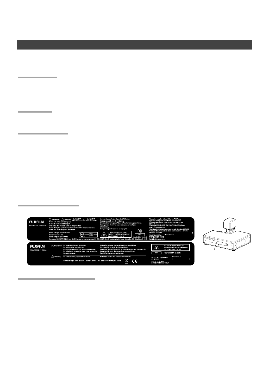
Laser Warning Stickers
Laser warning stickers are a xed to the side and interior of the product.
Specifi cations of laser source
• Wavelength: 455 nm
• Maximum Output: 95 W
Laser warning stickers
4
Page 8

NOTICES
Caution:
FCC Warning:
For Customers In Canada
Veri cation
Model Number: FP-Z5000
Trade Mark: Fuji lm
This device complies with Part 15 of the FCC Rules.
Operation is subject to the following two conditions:
(1) This device may not cause harmful interference, and (2) this device must accept any interference received,
including interference that may cause undesired operation.
Caution:
This equipment has been tested and found to comply with the limits for a Class A digital device, pursuant to
part 15 of the FCC Rules.
These limits are designed to provide reasonable protection against harmful interference when the equipment is operated in a commercial environment.
This equipment generates, uses, and can radiate radio frequency energy and, if not installed and used in accordance with the instruction manual, may cause harmful interference to radio communications. Operation
of this equipment in a residential area is likely to cause harmful interference in which case the user will be
required to correct the interference at his own expense.
FCC Warning:
To assure continued compliance, follow the attached installation instructions. This includes using the provided power cord and shielded interface cables when connecting to computer or peripheral devices. Also,
any unauthorized changes or modi cations to this equipment could void the user’s authority to operate this
device.
For Customers In Canada
CAN ICES-3(A)/NMB-3(A)
WARNING: This equipment is compliant with Class A of CISPR32. In a residential environment this equipment
may cause radio interference.
This product complies with the following EU Directives:
• RoHS Directive 2011/65/EU
• EMC Directive 2014/30/EU
• LVD Directive 2014/35/EU
Compliance with these directives implies conformity to applicable harmonized European standards (European Norms) which are listed on the EU Declaration of Conformity issued by FUJIFILM Corporation for this
product or product family.
This compliance is indicated by the following conformity marking placed on the product:
This marking is valid for non-Telecom products and EU harmonized Telecom products (e.g.Bluetooth).
5
Page 9

NOTICES
About the Icons
Disposal of Electrical and Electronic Equipment in Private Households In the European
Union, Norway, Iceland and Liechtenstein:
About the Icons
The symbols on the product represent the following:
AC
DC
Class II equipment (The construction of the product is double-insulated.)
Disposal of Electrical and Electronic Equipment in Private Households In the European
Union, Norway, Iceland and Liechtenstein:
This symbol on the product, or in the manual and in the warranty, and/or on its packaging indicates
that this product shall not be treated as household waste. Instead it should be taken to an applicable
collection point for the recycling of electrical and electronic equipment. By ensuring this product is
disposed of correctly, you will help prevent potential negative consequences to the environment and
human health, which could otherwise be caused by inappropriate waste handling of this product.
6
Page 10
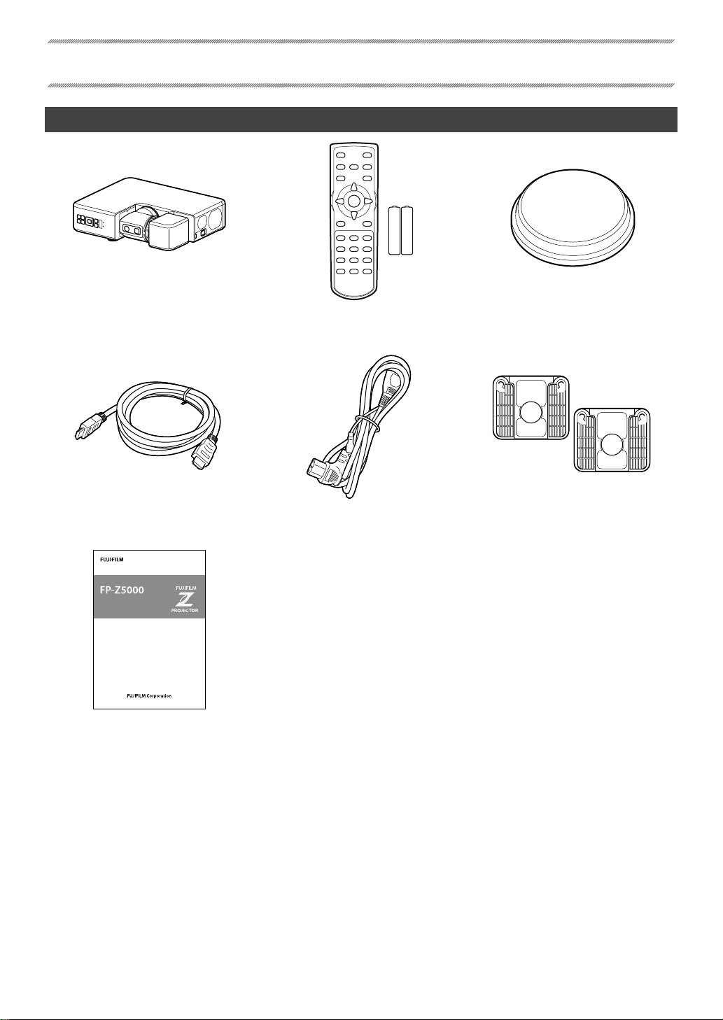
Package Contents
Introduction
Projector
HDMI cable (approximately
1.8m/5.9ft)
Projector
Basic Manual
(Installation and Basic Operation)
BL00005017-100
BL00005017-200
Remote control with
two AAA batteries
Power cable (approximately
3m/9.8ft)
Lens cap
Stand (×2)
Basic Manual (this manual)
7
Page 11

Parts of the Projector
Introduction
Item Name See page
Control panel 15
A
Intake vents 9
B
HDMI 3 connector 23
C
Power connector 16
D
Arm latch release
E
Head latch release
F
Lens
G
Status lamp
H
Temperature warning lamp
I
Remote receivers 25
J
Screw holes for attaching stands 10
K
* Compatible with Kensington MicroSaver security system locks.
17
26
Item Name See page
Interface (connector) panel 23
L
Model number plate (laser warning
M
sticker)
Speaker —
N
Security slot *
O
Exhaust vents 9
P
Adjustable feet
Q
Service connector
R
USB connector (5V DC power supply)
S
HDBaseT/LAN connector
T
HDMI 1 connector
U
HDMI 2 connector
V
8
4
—
23
Page 12

Installation
Spacing
Choosing a Location
Spacing
When installing the projector, choose a location where the vents
will be a safe distance from walls or other obstructions.
• Intake: 40 cm (1.3ft)
• Exhaust: 40 cm (1.3ft)
When installing two or more projectors side-by-side, leave a space of at least 80cm (2.6ft) between them.
You will also need to ensure that the warm air from the exhaust vents does not enter any of the projectors’
intake vents.
80cm
Intake Exhaust
40cm 40cm
4 CAUTION
Do not obstruct the vents. The build-up of heat inside the projector could cause fi re.
9
Page 13

Installing the Projector in Vertical Orientation
Using the Stands
Installing the Projector in Vertical Orientation
Before installing the projector in vertical orientation, attach the
supplied stands.
Installation
b TIP
Using the Stands
Before installing the projector in vertical orientation, attach the
supplied stands. Attach the stands using their built-in screws,
which screw into the attachment holes on the projector. When
attaching the stands, lay the projector at. The lens should be
in the storage position, the projector in standby mode, and the
power cable disconnected.
Open the legs after standing the projector on edge.
The supplied stand does not incorporate a height-adjustment mechanism.
4 CAUTIONS
• Be careful not to drop the projector when lifting it to attach the stands.
• Attach the stands securely. When using the stands, be sure the legs are fully open. If the stands
are not securely attached or the legs are not fully open when the projector is oriented vertically,
the projector could become unbalanced and tip.
10
Page 14

Installation
Lens Shift Range and Projection Distance
Lens Shift Range: Landscape Orientation
×
×
2
Projection Distance
Lens shifted
all the way up
Lens shifted all
the way down
Lens Shift Range and Projection Distance
Lens Shift Range: Landscape Orientation
V
Height (H)
W × 35% W × 35%
H×35
%
Projection Distance
Lens shifted
all the way up
Lens shifted all
the way down
1/2H
½ W
Width (W)
Center
of lens
½ HH × 82%
1/
H × 82%
V
H×35
H
%
Center of lens
More details on projection distance are
available via a simulator on the Fuji lm
website:
https://optics.fuji lm.com/projector/en/
spec/
Projection distance (cm/in), minimum
A
(projector zoomed all the way out) to
maximum (projector zoomed all the
way in)
Vertical distance from center of lens to
B
bottom of screen (cm/in)
11
Page 15

Projection Distances (Landscape Orientation)
Projection Distances (Landscape Orientation)
Screen dimensions (16∶9)
70 155× 87 / 61.0× 34.3 52 – 57 / 20.5 – 22.4 −115 to +28 / −45.3 to +11.0
80 177×100 / 69.7× 39.4 59 – 65 / 23.2 – 25.6 −131 to +32 / −51.6 to +12.6
90 199×112 / 78.3× 44.1 67 – 74 / 26.4 – 29.1 −148 to +36 / −58.3 to +14.2
100 221×125 / 87.0× 49.2 75 – 82 / 29.5 – 32.3 −164 to +40 / −64.6 to +15.7
120 266×149 / 104.7× 58.7 90 – 99 / 35.4 – 39.0 −197 to +48 / −77.6 to +18.9
150 332×187 / 130.7× 73.6 113 – 124 / 44.5 – 48.8 −247 to +60 / −97.2 to +23.6
200 443×249 / 174.4× 98.0 151 – 166 / 59.4 – 65.4 −329 to +80 / −129.5 to +31.5
250 553×311 / 217.7×122.4 189 – 208 / 74.4 – 81.9 −411 to +100 / −161.8 to +39.4
300 664×374 / 261.4×147.2 227 – 250 / 89.4 – 98.4 −493 to +120 / −194.1 to +47.2
Projection distance (cm/in)
A
min. zoom–max. zoom
Vertical shift (cm/in)
B
lowest to highestDiagonal (in) W× H (cm/in)
Installation
Screen dimensions (16∶10)
70 151× 85 / 59.4× 33.5 56 – 62 / 22.0 – 24.4 −112 to +27 / −44.1 to +10.6
80 172× 97 / 67.7× 38.2 64 – 71 / 25.2 – 28.0 −128 to +31 / −50.4 to +12.2
90 194×109 / 76.4× 42.9 72 – 80 / 28.3 – 31.5 −144 to +35 / −56.7 to +13.8
100 215×121 / 84.6× 47.6 81 – 89 / 31.9 – 35.0 −160 to +39 / −63.0 to +15.4
120 258×145 / 101.6× 57.1 97 – 107 / 38.2 – 42.1 −192 to +47 / −75.6 to +18.5
150 323×182 / 127.2× 71.7 122 – 134 / 48.0 – 52.8 −240 to +58 / −94.5 to +22.8
200 431×242 / 169.7× 95.3 163 – 179 / 64.2 – 70.5 −320 to +78 / −126.0 to +30.7
250 538×303 / 211.8×119.3 204 – 225 / 80.3 – 88.6 −400 to +97 / −157.5 to +38.2
300 646×363 / 254.3×142.9 245 – 270 / 96.5 – 106.3 −480 to +116 / −189.0 to +45.7
Screen dimensions (4∶3)
60 122× 91 / 48.0× 35.8 54 – 60 / 21.3 – 23.6 −121 to +29 / −47.6 to +11.4
70 142×107 / 55.9× 42.1 64 – 70 / 25.2 – 27.6 −141 to +34 / −55.5 to +13.4
80 163×122 / 64.2× 48.0 73 – 80 / 28.7 – 31.5 −161 to +39 / −63.4 to +15.4
90 183×137 / 72.0× 53.9 82 – 91 / 32.3 – 35.8 −181 to +44 / −71.3 to +17.3
100 203×152 / 79.9× 59.8 92 – 101 / 36.2 – 39.8 −201 to +49 / −79.1 to +19.3
120 244×183 / 96.1× 72.0 110 – 121 / 43.3 – 47.6 −241 to +59 / −94.9 to +23.2
150 305×229 / 120.1× 90.2 138 – 152 / 54.3 – 59.8 −302 to +73 / −118.9 to +28.7
200 406×305 / 159.8×120.1 185 – 203 / 72.8 – 79.9 −402 to +98 / −158.3 to +38.6
240 488×366 / 192.1×144.1 222 – 244 / 87.4 – 96.1 −483 to +117 / −190.2 to +46.1
b TIP
Figures are approximate, diff ering from the actual values by a few percent.
Projection distance (cm/in)
A
min. zoom–max. zoom
Projection distance (cm/in)
A
min. zoom–max. zoom
Vertical shift (cm/in)
B
lowest to highestDiagonal (in) W× H (cm/in)
Vertical shift (cm/in)
B
lowest to highestDiagonal (in) W× H (cm/in)
12
Page 16

Installation
Lens Shift Range: Portrait Orientation
H
×
×
Projection Distance
Lens shifted
all the way up
Lens shifted all
the way down
Lens Shift Range: Portrait Orientation
Width (W)
Height (H)
1/2V
½ H
H × 35%
V
Center
of lens
H × 35%
V
H×82
Projection Distance
Lens shifted
all the way up
Lens shifted all
the way down
%
½ WW × 82% W × 82%
1/2H
H×82
Center of lens
%
More details on projection distance are
available via a simulator on the Fuji lm
website:
https://optics.fuji lm.com/projector/en/
spec/
Projection distance (cm/in), minimum
A
(projector zoomed all the way out) to
maximum (projector zoomed all the
way in)
Vertical distance from center of lens to
B
bottom of screen (cm/in)
13
Page 17

Projection Distances (Portrait Orientation)
Projection Distances (Portrait Orientation)
Screen dimensions (16∶9)
70 87×155 / 34.3× 61.0 52 – 57 / 20.5 – 22.4 −132 to −23 / −52.0 to −9.1
80 100×177 / 39.4× 69.7 59 – 65 / 23.2 – 25.6 −151 to −27 / −59.4 to −10.6
90 112×199 / 44.1× 78.3 67 – 74 / 26.4 – 29.1 −169 to −30 / −66.5 to −11.8
100 125×221 / 49.2× 87.0 75 – 82 / 29.5 – 32.3 −188 to −33 / −74.0 to −13.0
120 149×266 / 58.7×104.7 90 – 99 / 35.4 – 39.0 −226 to −40 / −89.0 to −15.7
150 187×332 / 73.6×130.7 113 – 124 / 44.5 – 48.8 −282 to −50 / −111.0 to −19.7
200 249×443 / 98.0×174.4 151 – 166 / 59.4 – 65.4 −376 to −66 / −148.0 to −26.0
250 311×553 / 122.4×217.7 189 – 208 / 74.4 – 81.9 −470 to −83 / −185.0 to −32.7
300 374×664 / 147.2×261.4 227 – 250 / 89.4 – 98.4 −565 to −100 / −222.4 to −39.4
Projection distance (cm/in)
A
min. zoom–max. zoom
Vertical shift (cm/in)
B
lowest to highestDiagonal (in) W× H (cm/in)
Installation
Screen dimensions (16∶10)
70 85×151 / 33.5× 59.4 56 – 62 / 22.0 – 24.4 −134 to −17 / −52.8 to −6.7
80 97×172 / 38.2× 67.7 64 – 71 / 25.2 – 28.0 −153 to −19 / −60.2 to −7.5
90 109×194 / 42.9× 76.4 72 – 80 / 28.3 – 31.5 −172 to −22 / −67.7 to −8.7
100 121×215 / 47.6× 84.6 81 – 89 / 31.9 – 35.0 −191 to −24 / −75.2 to −9.4
120 145×258 / 57.1×101.6 97 – 107 / 38.2 – 42.1 −230 to −29 / −90.6 to −11.4
150 182×323 / 71.7×127.2 122 – 134 / 48.0 – 52.8 −287 to −36 / −113.0 to −14.2
200 242×431 / 95.3×169.7 163 – 179 / 64.2 – 70.5 −383 to −48 / −150.8 to −18.9
250 303×538 / 119.3×211.8 204 – 225 / 80.3 – 88.6 −479 to −60 / −188.6 to −23.6
300 363×646 / 142.9×254.3 245 – 270 / 96.5 – 106.3 −574 to −72 / −226.0 to −28.3
Screen dimensions (4∶3)
60 91×122 / 35.8× 48.0 54 – 60 / 21.3 – 23.6 −118 to −4 / −46.5 to −1.6
70 107×142 / 42.1× 55.9 64 – 70 / 25.2 – 27.6 −137 to −5 / −53.9 to −2.0
80 122×163 / 48.0× 64.2 73 – 80 / 28.7 – 31.5 −157 to −5 / −61.8 to −2.0
90 137×183 / 53.9× 72.0 82 – 91 / 32.3 – 35.8 −177 to −6 / −69.7 to −2.4
100 152×203 / 59.8× 79.9 92 – 101 / 36.2 – 39.8 −196 to −7 / −77.2 to −2.8
120 183×244 / 72.0× 96.1 110 – 121 / 43.3 – 47.6 −236 to −8 / −92.9 to −3.1
150 229×305 / 90.2×120.1 138 – 152 / 54.3 – 59.8 −295 to −10 / −116.1 to −3.9
200 305×406 / 120.1×159.8 185 – 203 / 72.8 – 79.9 −393 to −14 / −154.7 to −5.5
240 366×488 / 144.1×192.1 222 – 244 / 87.4 – 96.1 −471 to −16 / −185.4 to −6.3
b TIP
Figures are approximate, diff ering from the actual values by a few percent.
Projection distance (cm/in)
A
min. zoom–max. zoom
Projection distance (cm/in)
A
min. zoom–max. zoom
Vertical shift (cm/in)
B
lowest to highestDiagonal (in) W× H (cm/in)
Vertical shift (cm/in)
B
lowest to highestDiagonal (in) W× H (cm/in)
14
Page 18

Basic Operation
The Control Panel
Basic operations are performed using the control panel. The names and functions of the buttons on the control panel are given below.
Item Button Function
SOURCE Choose the input source.
A
LENS Adjust lens focus, shift, and zoom.
B
Selector (e/f/g/h) Navigate the menus.
C
ENTER Select the highlighted menu item.
D
Power Turn the projector on or switch it to standby.
E
Arm latch release Unlatch the rotating arm.
F
Head latch release Unlatch the projector head.
G
BACK Return to the previous menu.
H
MENU Display the menus used to adjust projector settings.
I
J
MUTE
Temporarily suspend projection and mute audio. Audio can be restored by
pressing any other button or by pressing the MUTE button again.
15
Page 19

On/Standby
Turning the Projector On
Switching to Standby
Turning the Projector On
Connect the supplied power cable to the projector and plug it
1
into a power outlet.
The projector will switch to standby mode.
The supplied power cable is for use exclusively
4 CAUTION
Press the power button to turn the projector on.
2
with FP-Z5000 projectors. Do not use it with
any other product.
Basic Operation
4 CAUTION
Switching to Standby
Pressing the power button while the projector is on displays a con rmation dialog. Press the button again to
switch the projector to standby. The cooling fan will turn o a few seconds later.
4 CAUTION
Do not look directly into the lens while the projector is on.
The lens latches cannot be released while the projector is on standby; check the position of the lens
and replace the lens cap before switching the projector to standby.
16
Page 20

Projector Settings
Rotating the Arm
Rotating the Projector Head
Rotating the Lens
To rotate the lens, release the latches by pressing the arm (A)
and head (B) latch releases and then rotate the lens to the desired position. After positioning the lens, press the releases again
to latch the lens in place.
b TIPS
Rotating the Arm
When the arm latch is disengaged by pressing the arm latch release, the arm can be rotated 90° in the direction shown.
b TIP
Rotating the Projector Head
When the head latch is disengaged by pressing the head latch
release, the projector head can be rotated 360° in 90° increments.
• The latches will re-engage automatically if not manually re-engaged within 10 seconds.
• The LED lights when the head latch release is pressed.
When the projector is oriented vertically, the arm can also
be rotated 90° in the other direction.
17
Page 21

4 CAUTIONS
Projector Settings
• Some portions of the projected image may not be visible depending on lens shift and the orientation of the lens.
• When rotating the lens, keep it supported and rotate it slowly.
• To protect the lens, the arm locks to prevent it
rotating in the direction shown when the projector head is oriented as shown in the illustration.
18
Page 22

Projector Settings
Focus
The sharpness of the projected image can be adjusted by focusing the projector.
ABC
Press the LENS button until focus settings are displayed.
1
Adjust focus using the selector (e/f/g/h).
2
Press BACK to exit.
3
b TIP
Focus can also be adjusted from the menus.
19
Page 23

Lens Shift
The position of the projected image can be adjusted using lens shift.
ABC
Press the LENS button until lens shift settings are displayed.
1
Projector Settings
ABC
Position the projected image using the selector (e/f/g/h).
2
Press BACK to exit.
3
• The selected shift position is stored when the lens is rotated.
b TIPS
• The previously-selected shift position is recalled when the lens latches.
• Lens shift can also be adjusted from the menus.
20
Page 24

Projector Settings
Zoom
The size of the projected image can be adjusted using zoom.
ABC
Press the LENS button until zoom settings are displayed.
1
Adjust the size of the projected image using the selector
2
(e/f/g/h).
Press BACK to exit.
3
ABC
b TIP
Zoom can also be adjusted from the menus.
21
Page 25

Projector Settings
Keystone Compensation
“Keystoning” (where the sides of the projected image are not parallel with the edges of the screen) can be
corrected using keystone compensation.
ABC ABC
Press the MENU button to display the menus.
1
Highlight Keystone using the selector (e/f) and press ENTER to display keystone settings.
2
Correct keystone distortion using the selector (e/f/g/h).
3
Press BACK to exit.
4
Keystone
22
Page 26

Connections
Connecting HDMI Devices
HDMI devices can be connected via the projector’s HDMI1, HDMI2, and HDMI3 connectors.
• Turn the HDMI device off and switch the projector to standby before connecting the cable. After
4 CAUTIONS
connecting the cable to both devices, turn the projector on fi rst and then turn on the HDMI
device.
• Some devices require an adapter and/or a dedicated cable.
b TIP
Use the HDMI 3 connector when the projector is in vertical orientation.
Connecting Third-Party Video Transmitters
Third-party video transmitters that support HDBaseT can be connected via the projector’s HDBaseT/LAN
(RJ45) connector.
• Use an STP LAN cable with category 5e shielding or better.
• The maximum distance that video can be transmitted over a LAN cable is 100m (328ft).
• Operation is not guaranteed with all HDBaseT-compatible devices or in all operating environ-
4 CAUTIONS
ments.
• The projector cannot be connected directly to networks operated by mobile communications
service providers, fi xed-network communications service providers, Internet service providers,
or other telecommunications carriers. Any connection to the Internet must be made via a router.
23
Page 27

Technical Notes
HDMI/HDBaseT
Supported Resolutions
Image quality may be reduced if the resolution of the input signal exceeds the resolution of the projector’s
panel.
HDMI/HDBaseT
Signal Resolution (pixels) Refresh rate (Hz)
VGA 640× 480
SVGA 800× 600
XGA 1024× 768
1280× 768
WXGA
SXGA
SXGA+ 1400×1050
WXGA+ 1440× 900
WSXGA+ 1680×1050
UXGA 1600×1200
WUXGA 1920×1200
SDTV (480i) 720× 480
SDTV (480p) 720× 480
SDTV (576i) 720× 576
SDTV (576p) 720× 576
HDTV (720p) 1280× 720
HDTV (1080p) 1920×1080
1280× 800
1366× 768
1280× 960
1280×1024
60
50
60/50HDTV (1080i) 1920×1080
24
Page 28

Technical Notes
The Remote Control
The names and functions of the buttons on the remote control are listed below.
Item Button Function
Power Turn the projector on or switch it to standby.
A
HDMI 2 Select HDMI2.
B
LIGHT Turn the button lights on for 10 seconds.
C
HDMI 3 Select HDMI3.
D
SOURCE Display input source selection options.
E
ROTATION Rotate the image up or down.
F
Selector
G
(e/f/g/h)
ENTER Select the highlighted menu item.
H
BACK Return to the previous menu.
I
SHIFT Adjust lens shift.
J
ZOOM Adjust zoom.
K
INSTALL Display projection options.
L
CORNER FIT Display corner fi t options.
M
Remote control lock
N
PICTURE Adjust settings for the projected image.
O
10-key pad Use when entering the remote control ID.
P
MUTE
Q
ID SET Enter the remote control ID.
R
INFO View projector information.
S
ASPECT Choose the aspect ratio.
T
PATTERN Display a test pattern.
U
FOCUS Adjust focus.
V
MENU Display the menus used to adjust projector settings.
W
KEYSTONE Display keystone compensation settings.
X
Volume Adjust the volume of the built-in speaker.
Y
HDBaseT Select HDBaseT.
Z
HDMI 1 Select HDMI1.
a
Navigate the menus.
Disable the remote control.
Be sure to aim the remote at the remote receiver
when performing this operation.
Temporarily suspend projection and mute audio.
Audio can be restored by pressing any other button
or by pressing the MUTE button again.
25
Page 29

Technical Notes
Indicator Lamps
Projector status is shown by whether the POWER, TEMP, and STATUS indicator lamps are on, ashing, or o .
Power lamp
TEMP (temperature
warning) lamp
STATUS lamp
The statuses shown by the condition of the indicator lamps are listed below.
Lamp
Projector statusPower TEMP STATUS
On (amber) Off Off Projector in standby mode.
On (white) Off Off Projector on.
On (white) Flashing (amber) Off Projector temperature elevated.
On (white) On (amber) Off Laser temperature elevated.
Off
On (white)
Flashing (white) Off Flashing (amber) Problem with optical engine.
Flashing (white) Off On (amber) Problem with power supply.
Off
On (amber) or
fl ashing (amber)
Problem with cooling fan.
26
Page 30

Regulatory
Emissions
Immunity
This product conforms to the following regulations related to product safety, environmental requirements
and electromagnetic compatibility (EMC).
Safety
• CSA C22.2 No. 60950-1
• UL 60950-1
• IEC 60950-1
• EN 60950-1
Laser Safety
• IEC 60825-1
• IEC 62471
• FDA CDRH CFR 1040.10
• FDA CDRH CFR 1040.11
Electro-Magnetic Compatibility
Emissions
• FCC CFR47, Part 15, Subpart B/ANSI C63.4, Class A - Unintentional Radiators
• CISPR32/EN55032 Class A - Information Technology Equipment
• ICES/NMB003 (A) - Information Technology Equipment
Immunity
• CISPR 24/EN55024 EMC Requirements - Information Technology Equipment
Environmental
• The product conforms to:
• EU Directive (2011/65/EU) on the restriction of the use of certain hazardous substances (RoHS) in electrical and electronic equipment and the applicable o cial amendment(s).
• EU Regulation (EC) No. 1907/2006 on the registration, evaluation, authorization and restriction of chemicals (REACH) and the applicable o cial amendment(s).
• EU Directive (2012/19/EU) on waste and electrical and electronic equipment (WEEE) and the applicable
o cial amendment(s).
• China Ministry of Information Industry Order No.39 (02/2006) on the control of pollution caused by
electronic information products, the hazardous substances concentration limits (SJ/T11363-2006), and
the applicable product marking requirement (SJ/T11364-2006).
Marking
• This product conforms to all relevant Canadian, US, and European directives, standards, safety, health and
environmental concerns. International packaging recycling marks conform to:
• EU Directive (2012/19/EU) on waste and electrical and electronic equipment (WEEE).
• EU Directive (94/62/EC) on packaging and packaging waste.
• China packaging recycling mark standard (GB18455-2001).
27
Page 31

Federal Communications Commission (FCC) warning
• A shielded-type power cord is required in order to meet FCC emission limits and also to prevent interference
to the nearby radio and television reception. It is essential that only the supplied power cord be used.
• Use only shielded signal cables to connect I/O devices to this equipment.
28
Page 32

 Loading...