

Page 1
Operation Manual
Version 2.0
2006. Mar
Page 2

2006. Mar
Page 3

Contents
2006. Mar
Contents
Part 1 Preparations Before Use ...................................................................... 1
1. Starting the Image Reader ................................................................................................. 2
2. About the Main Window ..................................................................................................... 4
Part 2 Reading Imaging Plates ........................................................................ 5
1. Setting the Reading Conditions..........................................................................................6
2. Setting the IP on the IP Stage ............................................................................................ 8
3. Setting the IP Stage on the FLA-7000 ...............................................................................8
4. Starting Reading ................................................................................................................9
Part 3 Reading Fluorescent Samples ........................................................... 13
1. Setting the Reading Conditions........................................................................................14
2. Setting a Fluorescent Sample on the FLUOR Stage........................................................17
3. Setting the FLUOR Stage on the FLA-7000 ..................................................................... 17
4. Starting Reading ..............................................................................................................17
Part 4 Reading Digitized Samples ................................................................ 21
1. Setting the Reading Conditions........................................................................................22
2. Setting a Digitized Sample on the FLUOR Stage.............................................................25
3. Setting the FLUOR Stage on the FLA-7000 ..................................................................... 25
4. Starting Reading ..............................................................................................................25
Part 5 Lasers and Filters, Other Settings ..................................................... 29
1. Registering Laser and Filter Combinations (Method) ....................................................... 30
2. Filter Module Settings (Filter Module) ..............................................................................31
2a. Registering Filters in the Image Reader ............................................................................................ 31
2b. Saving the Four Types of Filter Combinations .................................................................................... 34
2c. Recalling Four Types of Filter Combinations ...................................................................................... 35
2d. Registering a New Filter Name .......................................................................................................... 35
3. Other Settings (Preference...) ..........................................................................................36
3a. Settings for Scanning (Scan Settings) ............................................................................................... 36
3b. Selecting the File Format for Saving and the Analyzing Software to Launch (Image File Settings) ... 38
Part 6 Installing and Uninstalling the Software........................................... 41
1. Installation (For Windows®) .............................................................................................. 42
1a. Installation of FUJI USB Control Driver.............................................................................................. 42
1b. Installation of FUJI USB Function Driver............................................................................................ 47
1c. Installation of Image Reader FLA-7000 Software ..............................................................................48
2. Uninstallation (For Windows®) ..........................................................................................49
i
Page 4

2006. Mar
3. Installation (For MacintoshTM) ...........................................................................................50
4. Uninstallation (For MacintoshTM).......................................................................................50
Part 7 Troubleshooting ................................................................................... 51
1. Errors ............................................................................................................................... 52
2. Warnings ..........................................................................................................................52
ii
Page 5

Part
1
Preparations Before Use
Page 6
2006. Mar
1. Starting the Image Reader
1. Starting the Image Reader
Caution
Please note that the GUI screens may change without notice.
Note1:
The Image Reader FLA-7000 software is available in two types: a
Windows version, and a Macintosh version. Both versions have the
same functions.
This manual uses the screens of the Windows version. If you are
using the Macintosh version, follow the instructions in this manual,
except those of OS-related operations (such as starting and exiting
the software).
Note2:
The following computers are compatible:
OS: Windows XP Professional SP2 or later, Mac OS X 10.3 or later
Memory: 512 MB Interface: USB 2.0
Precautions for Use
Do not connect any USB devices other than the FLA-7000 to the
computer in which the Image Reader is installed. Otherwise, it may
cause malfunction.
During reading, do not use any USB devices other than the FLA7000 connected to the computer. If USB devices are used
simultaneously, image data may be lost.
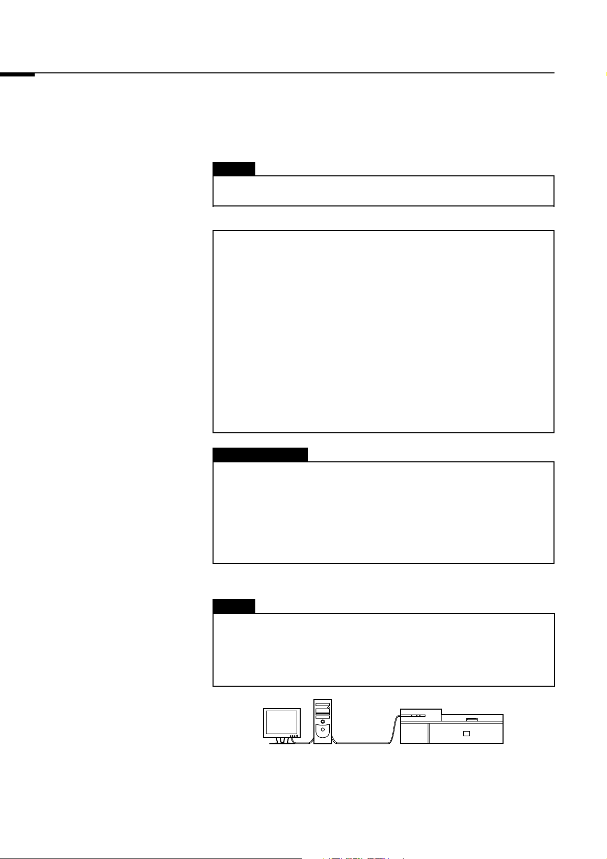
1-1 Turn on the FLA-7000 and peripheral devices.
Caution
If an Imaging Plate is inserted in the FLA-7000 before turning it on,
its scanned data cannot be guaranteed. The sensitivity of the
Imaging Plate may deteriorate, based on the self-diagnosis of the
FLA-7000.
USB
Connection
1-2 Turn on the computer.
2
Page 7
1. Starting the Image Reader
2006. Mar
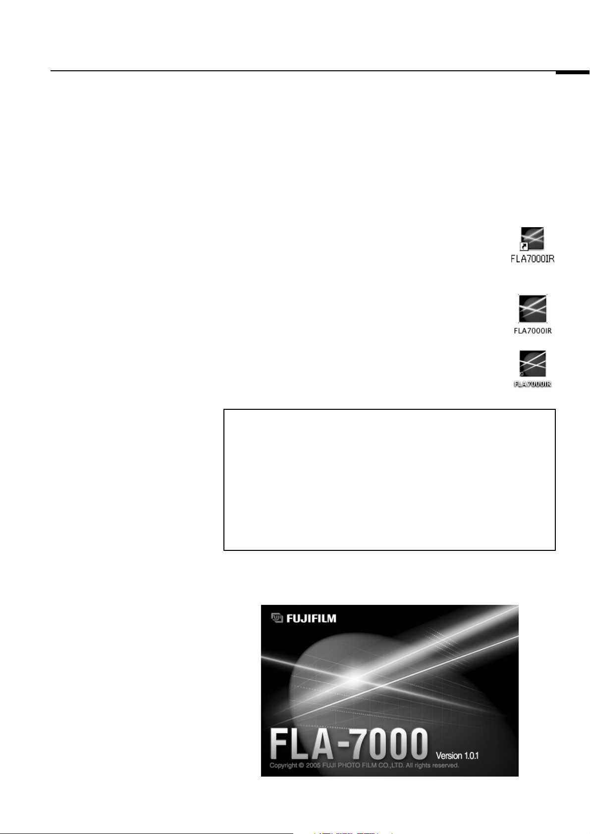
1-3 Make sure that the FLA-7000 has completed the warm-up. (Only
the power lamp on the upper left panel on the front of the FLA7000 is lit up when the warm-up is completed.)
Then, perform the procedures below.
For the Windows version:
Start the Image Reader FLA-7000 software from the
Startup menu, or use the shortcut key.
Shortcut Key
For the Macintosh version:
Double-click the alias or the software to start the
Image Reader FLA-7000 software.
Software
Note:
After starting the Image Reader, its condition is displayed in the
Status area.
• When disconnected:
Cannot recognize FLA-7000. Please check connection and power.
• During warm-up:
FLA-7000 is in self-diagnosis. Please wait.
• When reading is possible:
Ready
1-4 The main window of the Image Reader FLA-7000 software is
displayed.
Alias
3
Page 8
2006. Mar
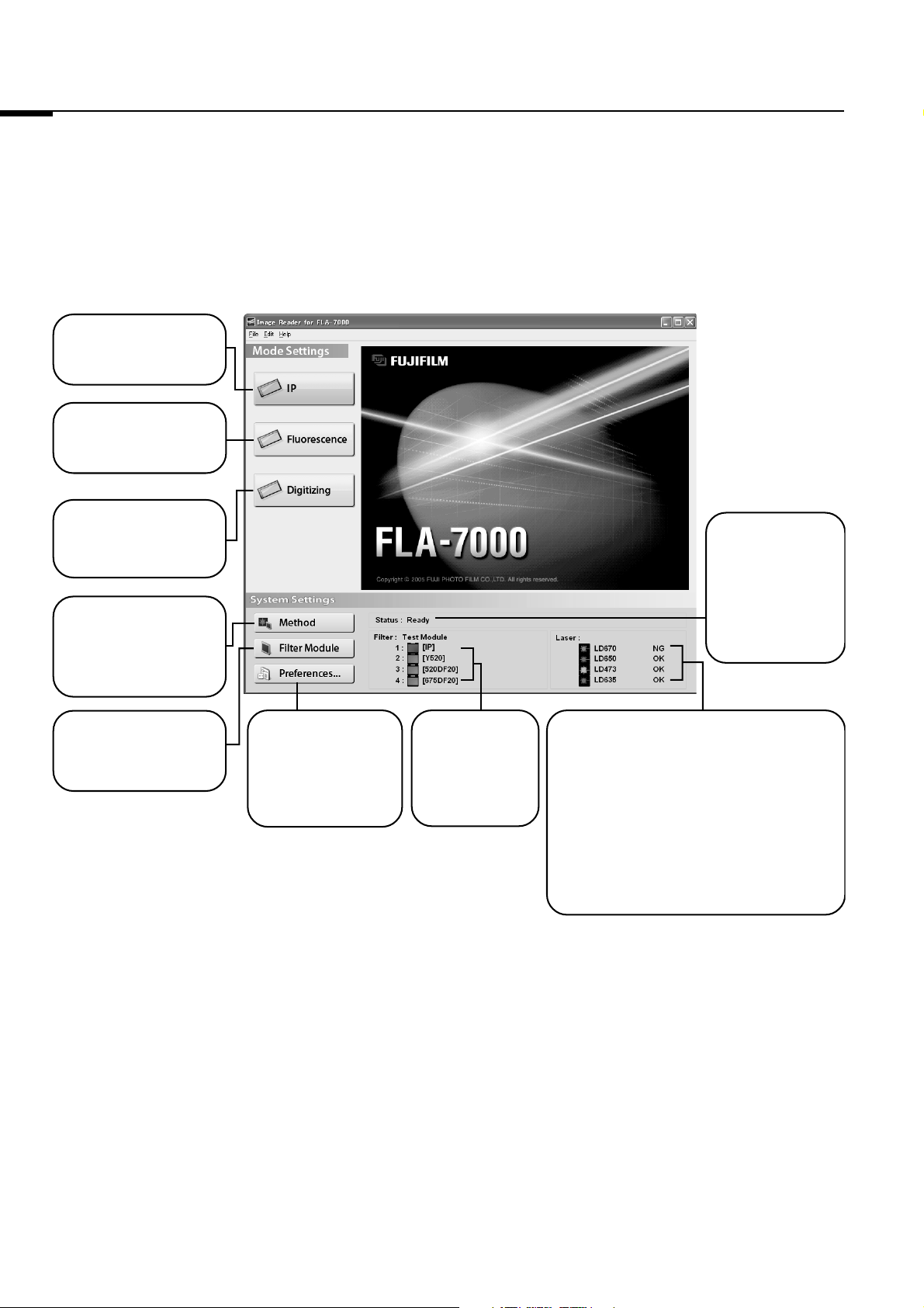
2. About the Main Window
IP Mode
Click when reading
an imaging plate.
Fluorescence Mode
Click when reading
fluorescent samples.
2. About the Main Window
Digitizing Mode
Click when performing
digitizing.
Method
Click this button to
register or erase
combinations of lasers
and filters.
Filter Module
Use this button to
change or register the
filter.
Preference...
Use this button to set
the display menu, file
format, or the Log/
Square Root of image
data type.
Filter
The loaded filters
are displayed.
Status
The status of the
FLA-7000 is
displayed.
Ready
The FLA-7000 is
ready for scanning.
Laser
The conditions of the loaded laser units are
displayed.
In this example, there are four types of laser units
loaded:
LD 670 nm laser,
LD 650 nm laser,
LD 473 nm laser,
LD 635 nm laser.
All the laser units except for the LD 670 nm laser
are ready for operation (OK).
The condition of the LD 670 nm laser shows that it
cannot be used (NG).
4
Page 9

Part
2
Reading Imaging Plates
Page 10
2006. Mar
1. Setting the Reading Conditions
1. Setting the Reading
Conditions
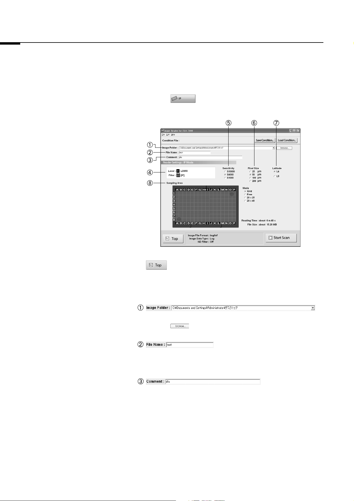
1-1 Click the button.
The Reader Settings window for the IP mode is displayed.
: Return to the main window from the IP mode.
1-2 Make these settings before reading IPs.
Refer to the following explanations of reading conditions when
making settings.
Specify where to save the file after reading.
Click the button.
:
Input the name of a file for saving data of a read image.
You may not start reading unless you input a file name.
The comment is saved with the image as a file, and can be viewed
with the analyzing software. Input it if necessary.
:
:
6
Page 11
1. Setting the Reading Conditions
2006. Mar
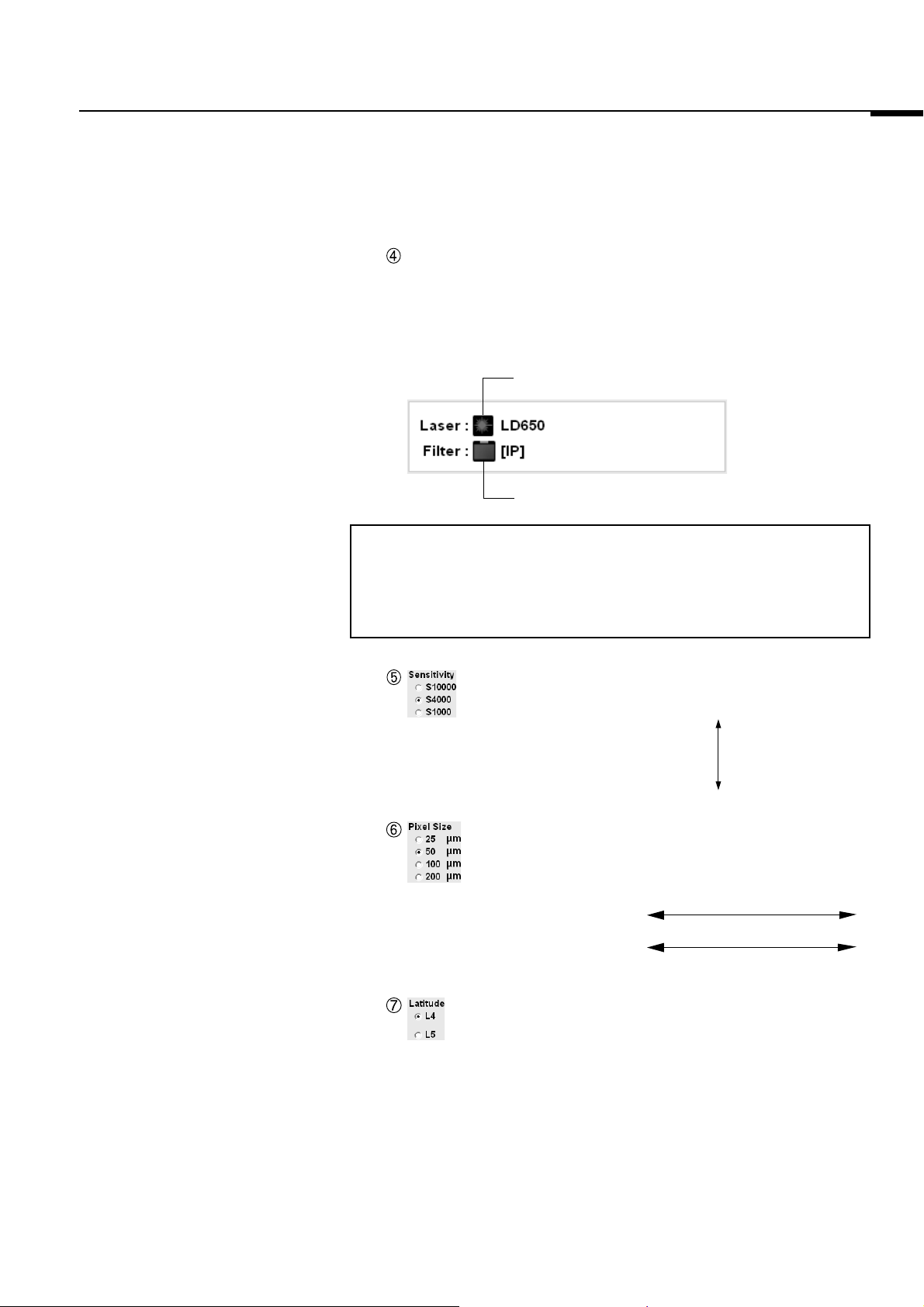
Before starting reading, make sure that the LD 650 nm laser is
shown and the IP filter is selected in the Setting field as shown
below.
In IP reading, the LD 650 nm laser and IP filter are selected
automatically.
The laser used for reading is displayed.
The filter used for reading is displayed.
Note:
To use the IP mode, the LD 650nm laser must be loaded, and the IP
filter must be set. If these conditions are not fulfilled, the Reader
Settings window for the IP mode cannot be accessed.
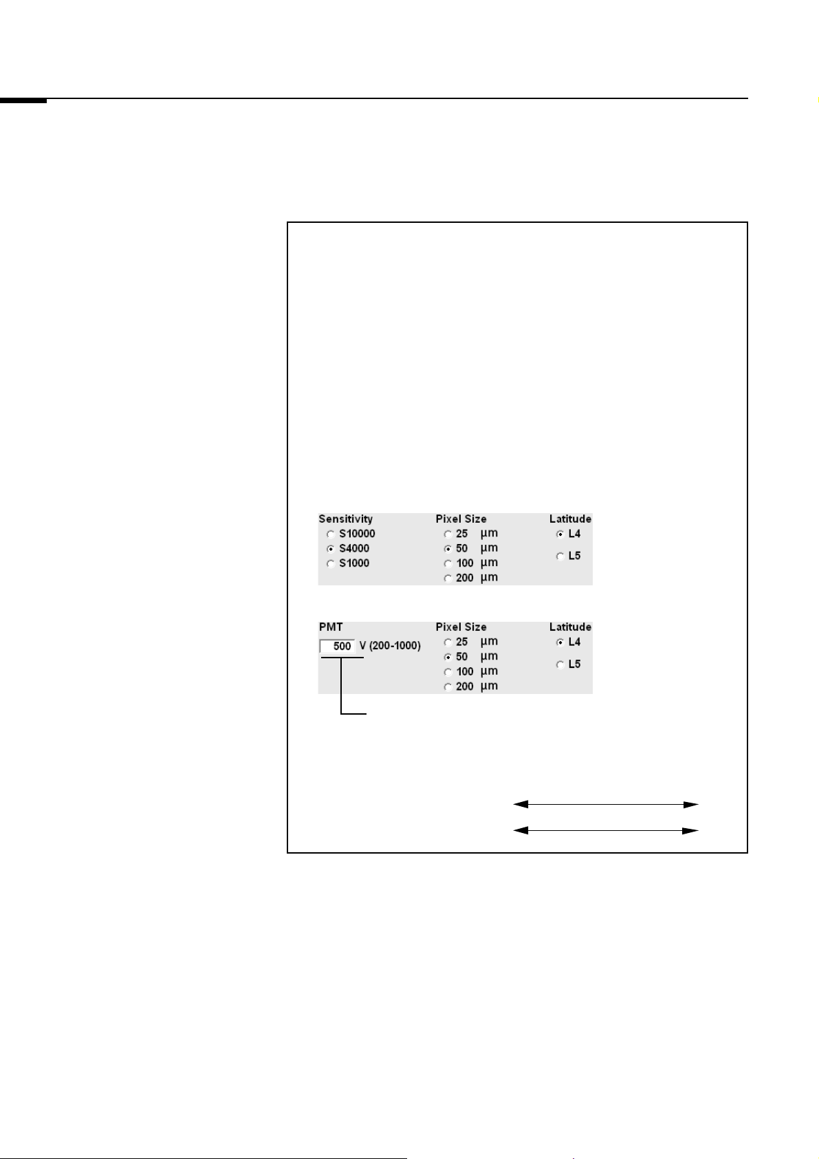
: Click to select from three types of reading sensitivity, as
shown on the left.
S10000
Sensitivity: high
Sensitivity: low
S1000
: Set the pixel size for reading. Click to select from one of
the 4 types, as shown on the left. A sample with a
smaller pixel size is analyzed more finely.
200 100 50 25 µm
Short Reading Time Long
Small Image File Size Large
: Specify the dynamic range. The dynamic range that can be
detected is bigger with L5 than with L4. If the signals of the
sample are in the L4 range, the density gradation is
represented more finely if L4 is selected.
7
Page 12
2006. Mar
2. Setting the IP on the IP Stage/3. Setting the IP Stage on the FLA-7000
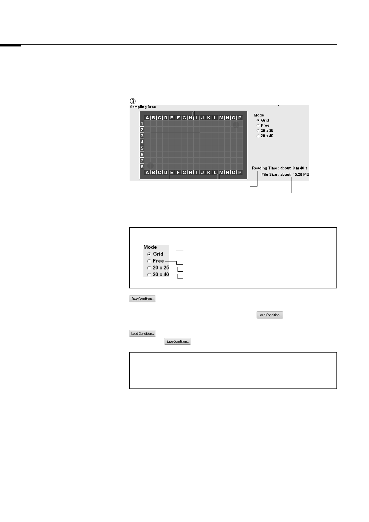
Estimated time until reading finishes.
Size of the file.
Drag and select the scanning area on the IP stage.
2. Setting the IP on the IP
Stage
Note:
Select this to specify the reading area based on the 2.5
cm grid lines on the IP stage.
Select this to specify the reading area arbitrarily.
Select this to specify a reading area of 20 cm x 25 cm.
Select this to specify a reading area of 20 cm x 40 cm.
: Use this button when saving the reading conditions in a file. You
may save reading conditions that are used frequently with this
function and recall them later with .
: Use this button when recalling reading conditions saved with
.
Note:
When starting the Image Reader, the settings information from the
previous session is displayed.
Set the IP on the IP stage.
For instructions on setting the IP, see the Fluorescent Image Analyzing
System FLA-7000 Operation Manual.
3. Setting the IP Stage on the
FLA-7000
8
Set the IP stage on the FLA-7000.
For instructions on setting the IP stage on the FLA-7000, see the
Fluorescent Image Analyzing System FLA-7000 Operation Manual.
Page 13
4. Starting Reading
2006. Mar
4. Starting Reading
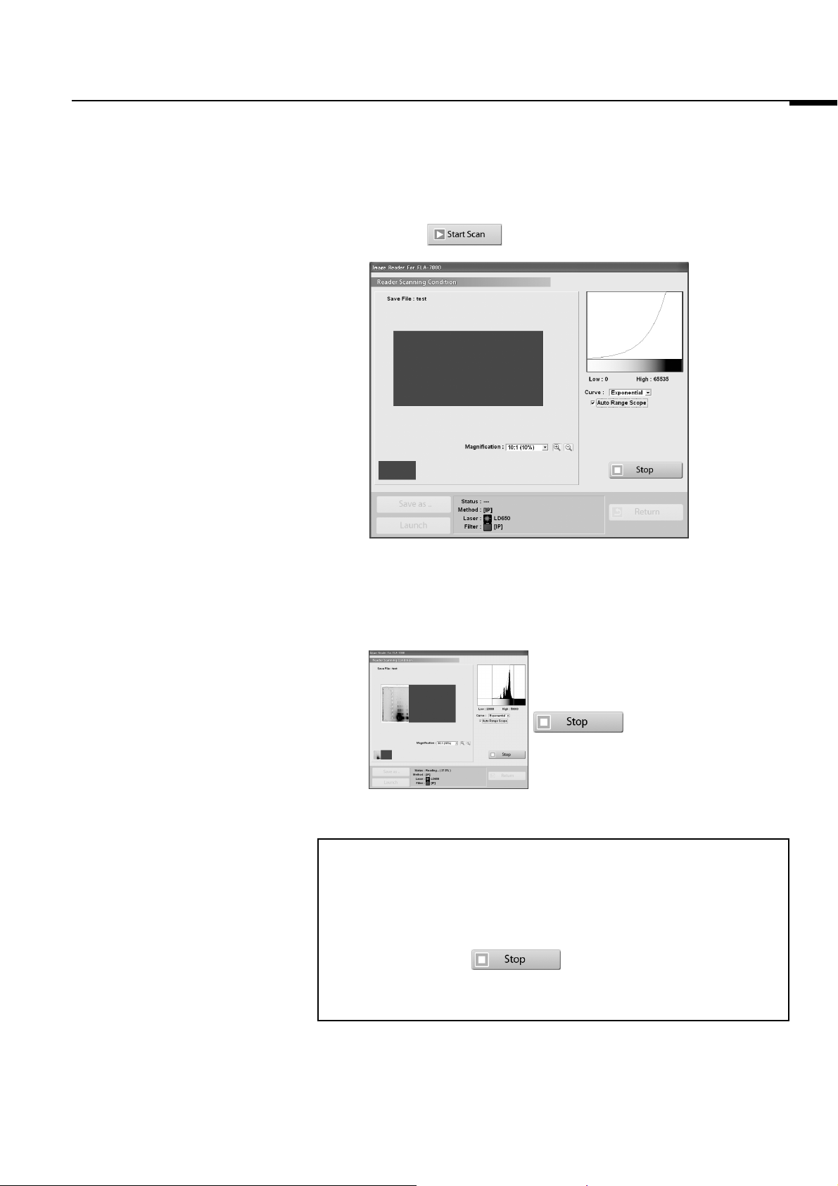
4-1 Click the button to start reading.
The scanned area is displayed in the real-time window, as shown
below.
The stage is read from the left towards the right.
Reading may be finished at any time
before the whole scanning area has
completed reading. Click the
button when you want to
finish reading.
Note1:
If you click Stop during reading, the part that has not been read yet
will be saved as an image with a data value of 0 (light intensity of 0).
Note2:
When you click the button, reading itself is canceled.
You cannot start reading again from the location where reading
stopped.
9
Page 14
2006. Mar
4. Starting Reading
4-2 When you want to change the display parameters of the real-time
window, refer to the explanations below.
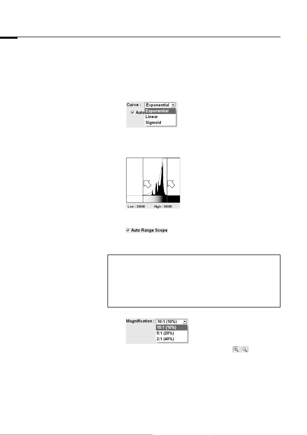
: Select the type of tone curve from the pull-
down menu.
Exponential: The exponential tone curve is
used to adjust gradations.
Linear: The linear tone curve is used
to adjust gradations.
Sigmoid: The sigmoid tone curve is
used to adjust gradations.
: Drag the adjuster.
You may adjust the density of the read
image.
Data of a lower light intensity that the line
on the left (Low value) will be displayed as
a completely white image, and data of a
higher light intensity than the line on the
right (High value) will be displayed as a
completely black image.
: If Auto Range Scope is checked, the Image
Reader automatically corrects the optimum
tone.
Note:
The Image Reader converts data read from samples to images that
have an information of 65536 tones, with 0 being the value for white,
and 65535 being the value for black.
The tones are indicated by the horizontal axis of the tone curve
graph.
: You may change the display area by
selecting a magnification ratio from
the pull-down menu. In addition, after
reading, if you click the display area
after clicking the buttons, the
clicked area can be enlarged or
reduced.
10
Page 15
4. Starting Reading
2006. Mar
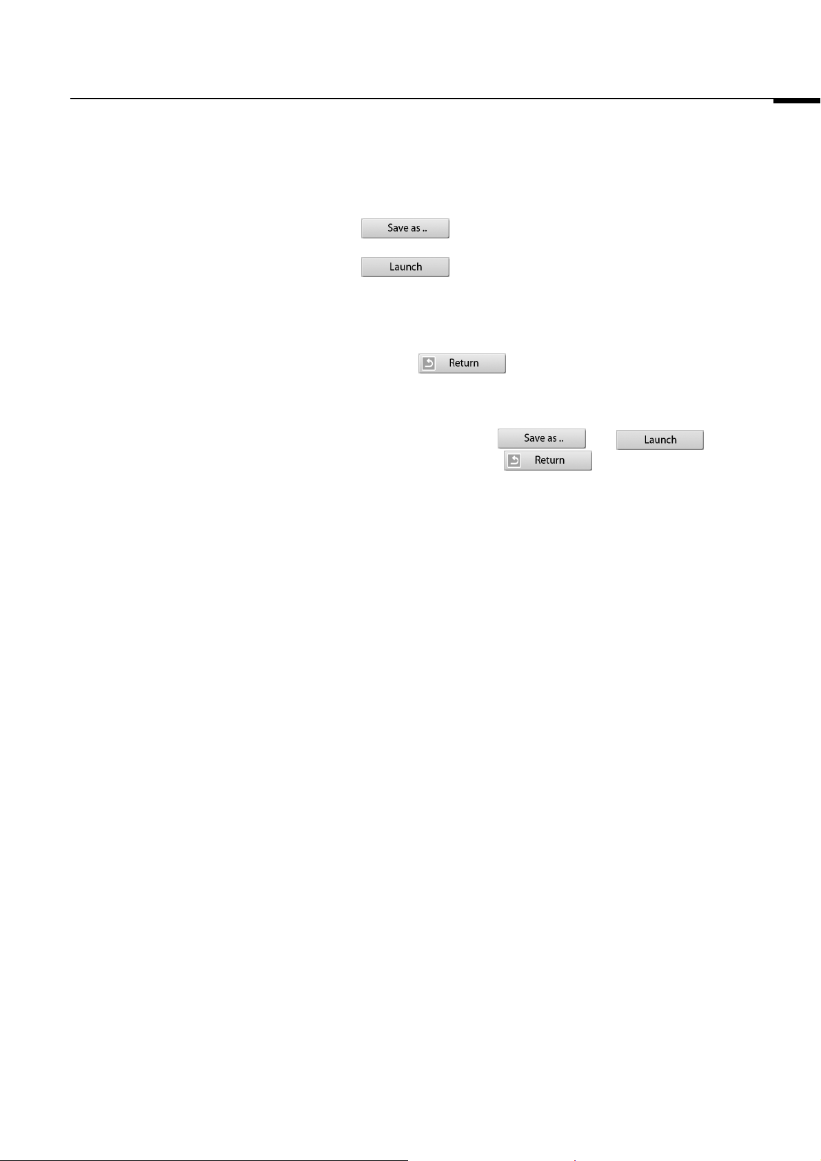
4-3 : Save the data with a different file name.
: Launch the registered analyzing software to
display the image.
4-4 To read a second IP continuously, carry out reading by following
the above procedures.
Click the button to return to the first Reader Settings
window.
Do not open the stage door of the FLA-7000 until the stage has
completely returned. If it is opened, close it immediately. When
scanning finishes, the and buttons
become active, but the button is grayed out until the
stage has completely returned.
4-5 Finish reading.
Before turning off the power of the FLA-7000, shut down the Image
Reader software.
11
Page 16
2006. Mar
4. Starting Reading
Note:
If the photo-multipliers (PMT) are replaced with a multi-alkali PMT,
the IP mode switches from that of the regular IP mode to a PMT
voltage adjustment mode. The PMT voltage adjustment mode differs
from the regular IP mode in that a sensitivity level that matches the
scanned sample can be set independently. Replacement of the
standard PMT with a multi-alkali PMT is done by a serviceman. For
details, contact an authorized dealer.
The Sensitivity settings differ from that of the regular IP mode. The
operation procedures for other settings are the same as those of the
regular IP mode. Follow the operation procedures of the regular IP
mode.
IP mode
PMT voltage adjustment mode
You may set the voltage to be applied to the PMT as an
integral value within the predetermined range. The larger
the value is, the higher the sensitivity, but noise will be
greater.
Small
Low High
200V 1000V
Value
Sensitivity
Large
12
Page 17

Part
3
Reading Fluorescent Samples
Page 18
2006. Mar
1. Setting the Reading Conditions
1. Setting the Reading
Conditions
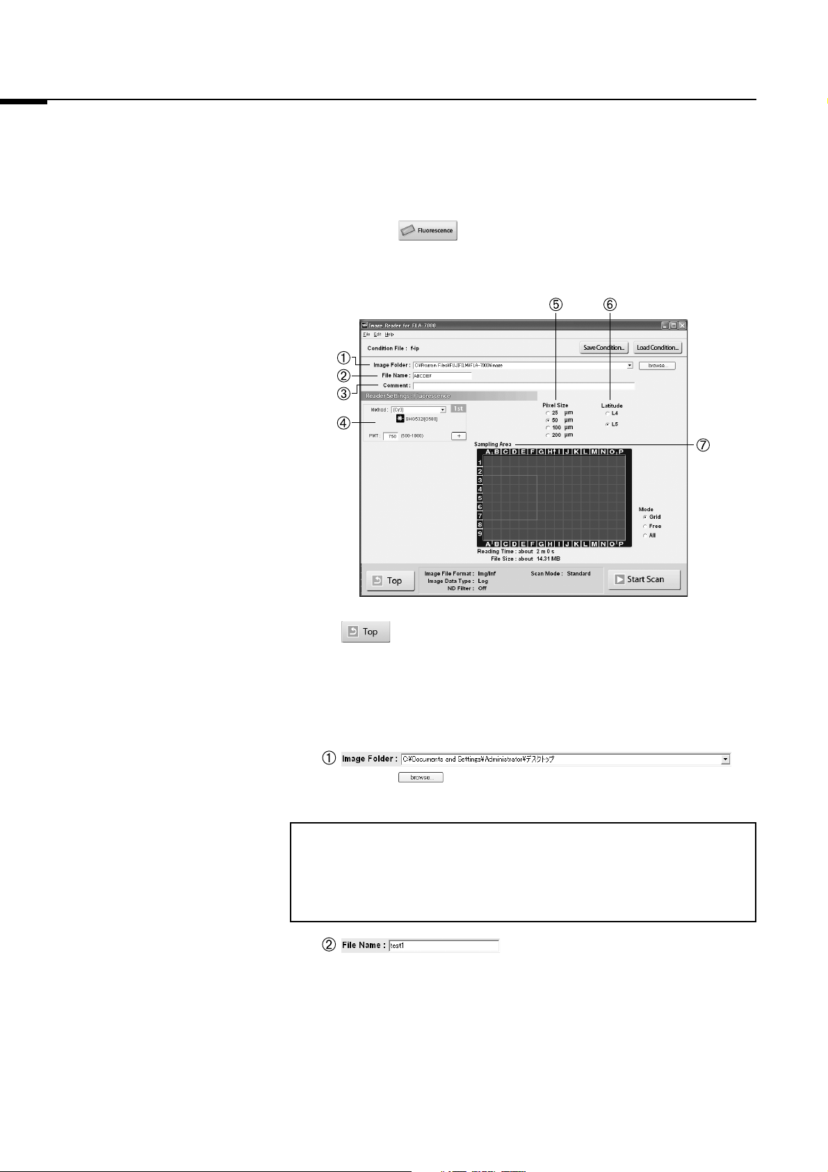
1-1 Click the button.
The Reader Settings window for the Fluorescence mode is
displayed.
: Return to the main window from the Fluorescence mode.
1-2 Make these settings before reading fluorescent samples.
Refer to the following explanations of reading conditions when
making settings.
Click the button and specify where to save the file after
reading.
Note:
When scanning multiple times, the image data is saved in the folder
with the name specified in File Name, which is automatically created
in the specified location.
:
Input the name of a file for saving data of an image.
You may not start reading unless you input a file name.
:
14
Page 19

1. Setting the Reading Conditions
000- 635- 1
File
name
Laser
name
Scan
number
2006. Mar
Note:
When the number of scans is between 2 and 4, the laser name and
scan number are automatically added to the specified name.
Example: If reading is set with the LD 635 nm laser, LD 473 nm
laser, LD 635 nm laser, and LD 635 nm laser, with "test"
as the file name, then the following files are created in the
"test" folder.
test-635-1
test-473
test-635-2
test-635-3
The comment is saved with the image as a file, and can be viewed
with the analyzing software. Input it if necessary.
: Scanning can be performed up to 4
times. The following items can be set.
Note:
: From the pull-down menu, select the Method
that corresponds with the sample. The
selected laser and filter combination is
displayed below.
: You may set the voltage to be applied to the
photo-multiplier tube (PMT) as an integral value
within the predetermined range. The larger the
value is, the higher the sensitivity.
200V 1000V
Small
Low High
Value
Sensitivity
:
Large
: Click the button to increase the number of scans,
and click the button to reduce the number of scans.
Up to 4 scans can be performed.
15
Page 20

2006. Mar
5
1. Setting the Reading Conditions
: Set the pixel size for reading. Click to select from one of
the 4 types, as shown on the left. A sample with a smaller
pixel size is analyzed more finely.
200 100 50 25 µm
Short Reading Time Long
Small Image File Size Large
: Specify the dynamic range. The dynamic range that can be
detected is bigger with L5 than with L4. If the signals of the
sample are in the L4 range, the density gradation is
represented more finely if L4 is selected.
Estimated time until reading finishes.
Size of the file. Expressed as file size per test x number of scans.
Drag and select the scanning area on the FLUOR stage.
Note:
Select this to specify the reading area based on the 2.
cm grid lines on the FLUOR stage.
Select this to specify the reading area arbitrarily.
Select this to specify the entire FLUOR stage as the
reading area.
16
Page 21

2. Setting a Fluorescent Sample on the FLUOR Stage/3. Setting the FLUOR Stage on the FLA-7000/4. Starting Reading
2006. Mar
: Use this button when saving the reading conditions in a file. You
may save reading conditions that are used frequently with this
function and recall them later with .
: Use this button when recalling reading conditions saved with
.
Note:
When starting the Image Reader, the settings information from the
previous session is displayed.
2. Setting a Fluorescent
Sample on the FLUOR
Stage
3. Setting the FLUOR Stage
on the FLA-7000
4. Starting Reading
Set the fluorescent sample on the FLUOR stage.
For instructions on setting the fluorescent sample, see the Fluorescent
Image Analyzing System FLA-7000 Operation Manual.
Set the FLUOR stage on the FLA-7000.
For instructions on setting the FLUOR stage on the FLA-7000, see the
Fluorescent Image Analyzing System FLA-7000 Operation Manual.
4-1 Click the button to start reading.
Displays the scan results of the 1st, 2nd, 3rd, and 4th
scan, starting from the left.
Click on the thumbnails to switch the display.
Displays information
related to the contents
of the currently
displayed scan.
17
Page 22

2006. Mar
4. Starting Reading
The scanned area is displayed in the real-time window, as shown
below.
The stage is read from the left towards the right.
Reading may be finished at
any time before the whole
scanning area has completed
reading. Click the
button when
you want to finish reading.
Note1:
If you click Stop during reading, the part that has not been read yet
will be saved as an image with a data value of 0 (light intensity of 0).
Note2:
When you click the button, reading itself is canceled.
You cannot start reading again from the location where reading
stopped.
4-2 When you want to change the display parameters of the real-time
window, refer to the explanations below and make settings.
: Select the type of tone curve from the pull-
down menu.
Exponential: The exponential tone curve is
used to adjust gradations
Linear: The linear tone curve is used
to adjust gradations.
Sigmoid: The sigmoid tone curve is
used to adjust gradations.
18
Page 23

4. Starting Reading
2006. Mar
: Drag the adjuster.
You may adjust the density of the read
image.
Data of a lower light intensity than the line
on the left (Low value) will be displayed
as a completely white image, and data of
a higher light intensity than the line on the
right (High value) will be displayed as a
completely black image.
: If Auto Range Scope is checked, the Image
Reader automatically corrects the optimum
tone.
Note:
The Image Reader converts data read from samples to images that
have an information of 65536 tones, with 0 being the value for white,
and 65535 being the value for black.
The tones are indicated by the horizontal axis of the tone curve
graph.
: You may change the display area by selecting a
magnification ratio from the pull-down menu. In
addition, after reading, if you click the display
area after click the buttons, the clicked
area can be enlarged or reduced.
4-3 : Save the data with a different file name.
: Launch the registered analyzing software to display
the image.
4-4 To read another fluorescent sample continuously, carry out reading
by following the above procedures.
Click the button to return to the first Reader Settings
window.
Do not open the stage door of the FLA-7000 until the stage has
completely returned. If it is opened, close it immediately.
When scanning finishes, the and
buttons become active, but the button is grayed out
until the stage has completely returned.
19
Page 24

2006. Mar
4. Starting Reading
4-5 Finish reading.
Before turning off the power of the FLA-7000, shut down the Image
Reader software.
20
Page 25

Part
4
Reading Digitized Samples
Page 26

2006. Mar
1. Setting the Reading Conditions
1. Setting the Reading
Conditions
1-1 Click the button.
The Reader Settings window for the Digitizing mode is displayed.
: Return to the main window from the Digitizing mode.
1-2 Make these settings before reading digitized samples.
Refer to the following explanations of reading conditions when
making settings.
Specify where to save the file after reading.
Click the button and specify where to save the file after
reading.
:
Input the name of a file for saving data of the image.
You may not start reading unless you input a file name.
:
The comment is saved with the image as a file, and can be viewed
with the analyzing software. Input it if necessary.
:
22
Page 27

1. Setting the Reading Conditions
2006. Mar
: Select the Method that corresponds
with the sample from the pull-down
menu.
The Method to be used for reading is displayed.
The contents of the laser and filter combination
to be used for reading are displayed.
Note:
To use the Digitizing mode, the LD 473 nm laser must be loaded
and the Y520 filter must be registered, or the SHG 532 nm laser
must be loaded and the O580 filter must be registered. If these
conditions are not fulfilled, the Reader Condition Settings window for
the Digitizing mode cannot be accessed.
: You may set the voltage to be applied to the photo-
multipliers (PMT) as an integral value within the
predetermined range.
: Set the pixel size for reading. Click to select one of the 4
types, as shown on the left. A sample with a smaller pixel
size will be analyzed more finely.
200 100 50 25 µm
Short Reading Time Long
Small Image File Size Large
: Specify the dynamic range. The dynamic range that can be
detected is bigger with L5 than with L4. If the signals of the
sample are in the L4 range, the density gradation is
represented more finely if L4 is selected.
23
Page 28

2006. Mar
1. Setting the Reading Conditions
Estimated time until reading finishes. Size of the file.
Drag and select the scanning area on the FLUOR stage.
Note:
Select this to specify the reading area based on the 2.5
grid lines on the FLUOR stage.
Select this to specify the reading area arbitrarily.
Select this to set the entire FLUOR stage as the reading
area.
: Use this button when saving the reading conditions in a file. You
may save reading conditions that are used frequently with this
function, and recall them later with .
: Use this button when recalling reading conditions saved with
.
Note:
When starting the Image Reader, the settings information from the
previous session is displayed.
24
Page 29

2. Setting a Digitized Sample on the FLUOR Stage/3. Setting the FLUOR Stage on the FLA-7000/4. Starting Reading
2006. Mar
2. Setting a Digitized Sample
on the FLUOR Stage
3. Setting the FLUOR Stage
on the FLA-7000
4. Starting Reading
After setting the digitized sample on the FLUOR stage, place the
fluorescent plate for digitizing on top of it.
For instructions on setting the digitize sample, see the Fluorescent Image
Analyzing System FLA-7000 Operation Manual.
Set the FLUOR stage on the FLA-7000.
For instructions on setting the FLUOR stage on the FLA-7000, see the
Fluorescent Image Analyzing System FLA-7000 Operation Manual.
4-1 Click the button to start reading.
The scanned area is displayed in the real-time window, as shown
below.
The stage is read from the left towards the right.
Reading may be finished any
time before the whole
scanning area has completed
reading. Click the
button when you
want to finish reading.
25
Page 30

2006. Mar
4. Starting Reading
Note1:
If you click Stop during reading, the part that has not been read yet
will be saved as an image with a data value of 0 (light intensity of 0).
Note2:
When you click the button, reading itself is canceled.
You cannot start reading again from the location where reading
stopped.
4-2 When you want to change the display parameters of the real-time
window, refer to the explanations below and make settings.
: Select the type of tone curve from the pull-
down menu.
Exponential: The exponential tone curve is
used to adjust gradations
Linear: The linear tone curve is used
to adjust gradations.
Sigmoid: The sigmoid tone curve is
used to adjust gradations.
: Drag the adjuster.
You may adjust the density of the read
image.
Data that is lighter than the line on the
left (Low value) will be displayed as a
completely white image, and data that is
darker than the line on the right (High
value) will be displayed as a completely
black image.
: If Auto Range Scope is checked, the Image
Reader automatically corrects the optimum
tone.
26
Page 31

4. Starting Reading
2006. Mar
Note:
The Image Reader converts data read from samples to images that
have an information of 65536 tones, with 0 being the value for white,
and 65535 being the value for black.
The tones are indicated by the horizontal axis of the tone curve
graph.
: You may change the display area by selecting a
magnification ratio from the pull-down menu. In
addition, after reading, if you click the display
area after click the buttons, the clicked
area can be enlarged or reduced.
4-3 : Save the data with a different file name.
: Launch the registered analyzing software to display
the image.
4-4 To read another digitized sample continuously, carry out reading by
following the above procedures.
Click the button to return to the first Reader Settings
window.
Do not open the stage door of the FLA-7000 until the stage has
completely returned. If it is opened, close it immediately. When
scanning finishes, the and buttons
become active, but the button is grayed out until the
stage has completely returned.
4-5 Finish reading.
Before turning off the power of the FLA-7000, shut down the Image
Reader software.
27
Page 32

2006. Mar
28
Page 33

Part
5
Lasers and Filters, Other Settings
Page 34

2006. Mar
r
1. Registering Laser and
Filter Combinations
(Method)
1. Registering Laser and Filter Combinations (Method)
Note:
Method settings are registered by a serviceman upon installation.
Under normal circumstances, it is not necessary to register these
settings.
You may register, change, and delete laser and filter combinations.
1-1 Click the button on the main window.
The following dialog box appears.
Names of the laser and
filter combinations
Click this button to delete laser
and filter combinations
1-2 Click the button.
The following dialog box appears.
However, combinations of lasers and filters that are not loaded
cannot be selected in the Reader Condition screen.
Click this button to edit
laser and filter
combinations
Click this button to registe
new laser and filter
combinations
Registered laser and
filter combinations
Name:
Input a name for the combination
to be registered.
Laser :
Select the type of laser. (You
may also select lasers that are
not actually loaded.)
Filter :
Select the type of filter. (You
may also select lasers that are
not actually loaded.)
30
Page 35

2. Filter Module Settings (Filter Module)
2006. Mar
1-3 Input a name for the combination, select the type of laser and filter,
and click the button. The laser and filter combination is
registered .
Note:
Click the and
buttons to delete or change a
registered Method.
Methods initially registered as default
cannot be deleted or edited.
The Methods marked with [**] are the
Methods that are initially set as
default.
2. Filter Module Settings
(Filter Module)
2a. Registering Filters in the
Image Reader
1-4 Click the button.
Note:
Filter Module settings are registered by a serviceman upon
installation.
Under normal circumstances, it is not necessary to register these
settings.
After exchanging the filters of the FLA-7000, you must register the
exchanged filters in the Image Reader.
Note:
If filters are not registered in the Image Reader, they are not
displayed in the Image Reader window, even if they are physically
set in the FLA-7000.
The following explains the method for registering filters in the Image Reader
when the [605DF40] is set in filter module position No.2 (second from the
back).
31
Page 36

2006. Mar
Caution
When removing the filter module, make sure to press the
Filter Settings window.
If the filter module is forcibly removed, the part where the filter
comes in contact with the photo-multipliers (PMT) will become
damaged.
2a-1 Click the button on the main window.
The following window appears and the filter module moves to a
position where it can be taken out.
Use this button to set a
filter in the Image Reader
It is also possible to use
the mouse to drag-and-drop
2. Filter Module Settings (Filter Module)
button and remove it after the window changes to the
Use this button to remove a filter
in the Image Reader
List of filters currently
registered in the
software
Filters marked with
[**] are the filters that
are initially set as
default
Corresponds to the
numbers (4,3,2,1) on the
filter tray
Use this button when loading
saved filter combinations
Use this button when saving
filter combinations as a file
: Use this button to add a new filter to the filter list.
: Use this button to change the name or color of the
displayed icon for the registered filter. Default filters ([**]) cannot be edited.
: Use this button to delete a registered filter. Default filters ([**]) cannot be deleted.
2a-2 Exchange the filter of the FLA-7000.
For instructions on exchanging the filter of the FLA-7000, see the
Fluorescent Image Analyzing System FLA-7000 Operation Manual.
32
Page 37

2. Filter Module Settings (Filter Module)
2006. Mar
2a-3 Click filter position No. 2.
A red frame appears around the selected filter position.
2a-4 Select [605DF40] from the Filter List.
The selected item is highlighted in blue.
2a-5 Click the button.
It is also possible to drag-and-drop the selected filter to filter
position No. 2.
33
Page 38

2006. Mar
2. Filter Module Settings (Filter Module)
Filter position No. 2 changes to [605DF40].
Note:
Click the button to keep the filter position empty after removing
a filter.
2b. Saving the Four Types of
Filter Combinations
2a-6 Click the button.
You may save four types of filter combinations that are currently displayed.
Note:
Exchanging the module and saving/recalling filter combinations can
be managed more easily if each user has their own filter module.
2b-1 Click the button on the main window.
2b-2 Click the button.
The following dialog box appears.
Filter Module Name:
Input a name for the filter
combination.
34
2b-3 After inputting a name for the filter combination, click the
button.
The filter combation is saved.
2b-4 Click the button.
Page 39

2. Filter Module Settings (Filter Module)
2006. Mar
2c. Recalling Four Types of
Filter Combinations
You may recall four types of filter combinations that are currently registered.
2c-1 Click the button on the main window.
2c-2 Click the
button.
The following dialog box is displayed.
2c-3 Select the name of the filter combination you want to recall, and
click the button.
The filter combination is recalled.
2d. Registering a New Filter
Name
2c-4 Click the button.
You may register a filter name.
2d-1 Click the button on the main window.
2d-2 Click the button.
The following dialog box appears.
Name:
Input a name for the filter.
Icon:
Select the color of the filter icon to
be displayed in the software.
35
Page 40

2006. Mar
3. Other Settings (Preference...)
2d-3 Select the filter name and icon color you want to register, and click
the button.
The filter is newly registered.
Note:
To delete or edit the register filter name, select the
filter name and click the or button.
Methods initially registered as default cannot be
deleted or edited.
3. Other Settings
(Preference...)
3a. Settings for Scanning
(Scan Settings)
2d-4 Click the button.
These are settings that are carried out when specifying settings for reading
samples.
Depending on the reading mode, there may be some functions that cannot
be used.
3a-1 Click the button on the main window.
3a-2 Click the tab.
The following dialog box appears.
36
Page 41

3. Other Settings (Preference...)
2006. Mar
3a-3 For each of the following items, refer to the explanations below and
click the radio button.
When detecting a very small sample amount, the Log
format is more effective, because the low-density areas
are converted to the gray scale more finely in the Log
format. Log format is also recommended for reading
gels stained with CBB or silver in the Digitizing mode.
The image will have a low background and clear
differences in density.
If there are large sample amounts in the IP,
Fluorescence, or Digitizing modes, the Root format is
more effective.
Note:
The following software versions are required for quantitative analysis
of images read in the Root format. Root format files cannot be
opened properly with older software versions.
For Windows:
Science Lab 2003 (Multi Gauge Ver.2.1, Colony Ver.1.1, L-Process
Ver.2.1) or later versions
For Macintosh:
Science Lab 2003 (Image Gauge Ver.4.2, L-Process Ver.2.1) or
later versions
Uses specific image shading correction data
that was adjusted in accordance with each
laser in the Fluorescence mode.
Correction settings will be added in the
Fluorescence mode.
You will be able to select from optional image
shading correction data.
Note:
Registration of the correction settings list is performed by a
serviceman. Please contact the dealer where you purchased the
FLA-7000, or contact Fuji Photo Film.
Does not use ND filter for adjusting light
intensity.
Uses ND filter for adjusting light intensity.
37
Page 42

2006. Mar
3. Other Settings (Preference...)
If select Quick, reading time would become shorter.
However, noise would stand out during reading.
The reading time varies depending on the setting image size
and the scanning area.
In case of reading the whole area of FLUOR stage,
the reading time are as follows:
< Standard Mode >
200um : 210sec, 100um : 210sec, 50um : 330sec, 25um : 450sec
< Quick Mode >
200um : 150sec, 100um : 150sec, 50um : 210sec, 25um : 330sec
3a-4 A function for supporting new stages in the future.
3a-5 Click the button.
3b. Selecting the File
Format for Saving
and the Analyzing
Software to Launch
(Image File Settings)
These are settings for saving images. Depending on the scanning mode,
there may be some functions that cannot be used.
3b-1 Click the button on the main window.
3b-2 Click the tab.
The following dialog box appears.
38
Page 43

3. Other Settings (Preference...)
2006. Mar
3b-3 Refer to the explanations below and click a radio button.
The standard file format of the Fuji Film BAS/FLA series. Each
file is saved as a combination of an information file (inf file) and
a raster file (img file).
The Fuji Film Science Lab or Array Gauge may be used for
analysis.
In combination with an img file and inf file, a read image can also
be saved in TIFF file format. For TIFF files, image data type is
always set to Linear format.
3b-4 Click the button, and select the specified analyzing software.
39
Page 44

2006. Mar
40
Page 45

Part
6
Installing and Uninstalling the Software
Page 46

2006. Mar
1. Installation (For Windows®)
1. Installation
(For Windows®)
1a. Installation of FUJI USB
Control Driver
It installs in the following sequence.
1a. Installation of FUJI USB Control driver
1b. Installation of FUJI USB Function driver
1c. Installation of Image Reader FLA-7000 software
Note:
The computer and FLA-7000 should not be connected with a USB cable
during the operation.
1a-1 Open the control panel and click “Printers and Other Hardware”.
1a-2 Click the “Add Hardware”.
1a-3 Click the “Next” button.
42
Page 47

1. Installation (For Windows®)
2006. Mar
1a-4 Select “Yes, I have already connected the hardware” and click the
“Next” button.
1a-5 Select “Add a new hardware device” and click the “Next” button.
1a-6 Select “Install the hardware that manually select from a list
[Advanced]” and click the “Next” button.
43
Page 48

2006. Mar
1. Installation (For Windows®)
1a-7 Select “Show All Devices” and click the “Next” button.
1a-8 Click “Have Disk...” button.
1a-9 Click “Browse...” button.
1a-10 Set the folder in which a file is saved to FLA-7000 CD-ROM.
44
Page 49

1. Installation (For Windows®)
2006. Mar
1a-11 Open the FUJIUSB control folder.
1a-12 Select a DevMng.inf file and click the “Open” button.
1a-13 Click the “OK” button.
1a-14 Click the “Next” button.
45
Page 50

2006. Mar
1. Installation (For Windows®)
1a-15 Click the “Next” button.
1a-16 Click the “Continue Anyway” button.
1a-17 Click the “Finish” button.
46
Page 51

1. Installation (For Windows®)
2006. Mar
1b. Installation of FUJI USB
Function Driver
1b-1 Connect the USB cable and turn ON the power switch of the FLA-
7000.
Note:
Perform this operation, or the personal computer may be reset.
1b-2 Click the “Next” button.
1b-3 Click the “Finish” button.
47
Page 52

2006. Mar
1. Installation (For Windows®)
1c. Installation of
Image Reader FLA-7000
Software
1c-1 Insert the installation CD-ROM of FLA-7000.
1c-2 Click the setup icon.
1c-3 Click the “Next” button.
1c-4 Click the “Install” button.
1c-5 Click the “Finish” button.
48
Page 53

2. Uninstallation (For Windows®)
2006. Mar
2. Uninstallation
(For Windows®)
2-1 Open the control panel and select “Add or Remove program”.
2-2 Select Image Reader FLA-7000 and click the “Remove” button to be
deleted.
➟ A progress bar is displayed and uninstallation is started.
Note:
Connection files created after installation of the reader software are
deleted. Correction files such as shading data is required to read by
FLA-7000. They arelocated in Data folder of FLA-7000 folder. The files
you wish to keep must be saved outside the FLA-7000 folder.
49
Page 54

2006. Mar
3. Installation (For MacintoshTM) / 4. Uninstallation (For MacintoshTM)
3. Installation
(For MacintoshTM)
Installation of FLA-7000
4. Uninstallation
(For MacintoshTM)
To install Image Reader FLA-7000 software, follow the procedure described
below.
< For Mac OS10.4 >
3-1 Double-click the “FLA-7000 Install CD” icon to open it.
3-2 Click the “FLA-7000.pkg” icon.
3-3 Click the “Continue” button on the “Introduction” screen.
3-4 Click the “Continue” button on the “Installation Destination” screen.
3-5 Click the “Upgrade” button on the “Installation Type” screen.
3-6 Provide the name and password of the administrator.
3-7 Click the “close” button on the “Finish Up” screen.
Move the FLA-7000 folder contained in the Application folder on the Machintosh
HD to your Trash bin.
Note:
Connection files created after installation of the reader software are
deleted. Correction files such as shading data is required to read by
FLA-7000. They arelocated in Data folder of FLA-7000 folder. The files
you wish to keep must be saved outside the FLA-7000 folder.
50
Page 55

Part
7
Troubleshooting
Page 56

2006. Mar
1. Errors/2. Warnings
1. Errors
2. Warnings
An error is the condition in which all of the reading modes of the FLA-7000
cannot be used.
When a warning occurs, the indicator lamps make a sound (“Be-beep, bebeep, be-beep”).
An error message dialog box is displayed on the Image Reader screen
displayed on the computer.
Please contact Fuji Photo Film with the 4-digit Error Code and the 8-digit
number inside the parentheses.
The following are examples of warnings that are displayed as a message in
the Image Reader window. If a displayed message includes instructions,
please follow them.
Message
Filter module has not been setup.
Push the filter module button and
set up the filter module.
The combination of the lasers and
filters could be inappropriate.
Check the lasers and filters.
Meaning and Countermeasure
Meaning:
• A filter module has not been set.
• Press the filter module button, and
set a filter module.
Countermeasure:
Confirm that a filter module is set.
Meaning:
There is a possibility that the laser
and filter combination is
inappropriate. Please check the
laser and filter.
Countermeasure:
• Confirm the Methods registered. It
is possible that the laser and filter
combination is inappropriate.
• Confirm that the filter specified in
the Image Reader is actually set.
52
Page 57

2. Warnings
2006. Mar
Laser error occurred.
Use other lasers.
Failed to retrive picture data from
PC.
Check the PC setting.
Meaning:
• A laser error has occurred.
• Use a different laser.
Countermeasure:
• An error has occurred with the
laser.
• If an error occurs even after
restarting the instrument, call a
serviceman.
• It is possible to scan using a
different laser.
Meaning
• There was a failure in reading the
image data from the computer.
• Check the computer environment.
Countermeasure:
• It is possible that the computer's
processing ability has degraded.
• Check the computer once, when
there are no devices connected to
it and no software started.
PMT error occurred.
Use low sensitivity for the setting.
The file name is already used.
Close the SampleSetDoor or
FilterChangeDoor.
Meaning:
• An overexposure error has
occurred.
• Scan with low sensitivity settings.
Countermeasure:
• Overexposure has been detected
outside of the scanning area.
• If an error occurs even after
restarting the instrument, call a
serviceman.
Meaning:
Close the sample set door or the
filter change door.
Countermeasure:
Close the sample set door or the
filter change door.
53
Page 58

2006. Mar
2. Warnings
Note:
If an error message is displayed, a serviceman should take the
countermeasures to resolve the trouble.
Please contact the dealer where you purchased the FLA-7000, or
contact Fuji Photo Film.
Fuji Photo Film Co., Ltd.
2-26-30 Nishi Azabu, Minato-ku
Tokyo, Japan 106-8620
TEL: +81-3-3406-2201
FAX: +81-3-3406-2158
e-mail: sghelp@fujifilm.co.jp
For technical questions, send an e-mail to the following address.
e-mail: sginfo@fujifilm.co.jp.
54
 Loading...