

Page 1
Installation Manual
Rail Mounting Base "RMA-C1"
Thank you for purchasing the rail mounting base "RMA-C1." The base allows you to install your FRENIC-Mini to a DIN rail 35 mm
(1.38 in) wide.
1. Check that:
(1) A rail mounting base is
contained in the package.
(2) The rail mounting base was not
damaged or dented during
transportation.
(3) The rail mounting base is the
model you ordered. You may
check the model name (see the
table below) printed on the
nameplate (shown at the right)
to ensure it matches your
inverter.
(4) If the rail mounting base is
model RMA-C1-2.2 or
RMA-C1-3.7, four screws
(M4x12) are also contained in
the package.
If you suspect the product is not
working properly or if you have any
questions about the product, contact
the shop where you bought the
product or your local FUJI branch
office.
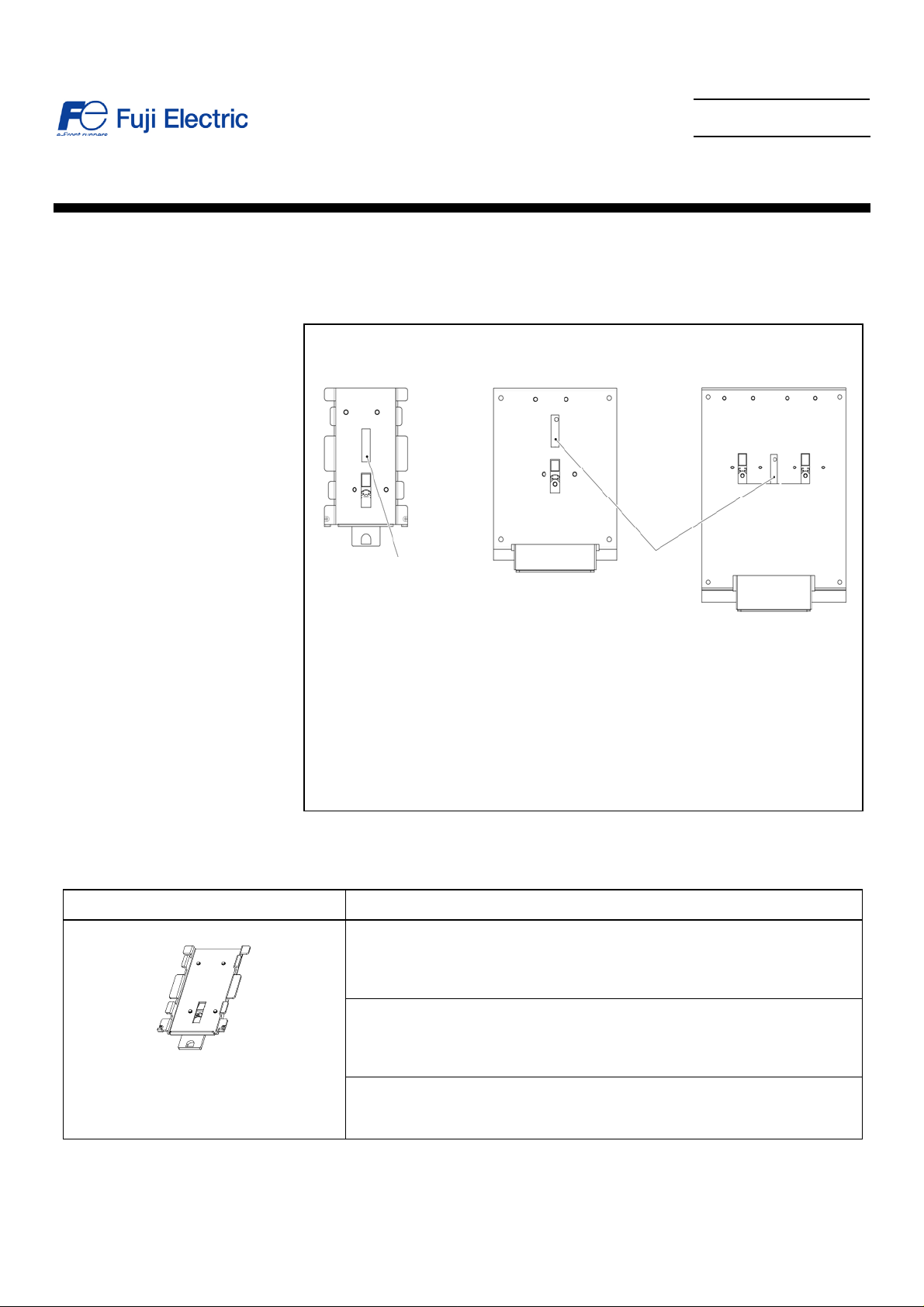
2. Rail Mounting Base Models and Applicable Inverter Models
RMA-C1-0.75 RMA-C1-2.2 RMA-C1-3.7
Nameplate
Nameplate
RMA-C1-0.75
Rail Mounting Base Models Applicable Inverter Models
FRNF12C1S-2U
FRNF25C1S-2U
FRNF50C1S-2U
FRN001C1S-2U
FRNF12C1S-7U
FRNF25C1S-7U
FRNF50C1S-7U
FRN001C1S-7U
FRNF12C1S-6U
FRNF25C1S-6U
FRNF50C1S-6U
- 1 -
Page 2
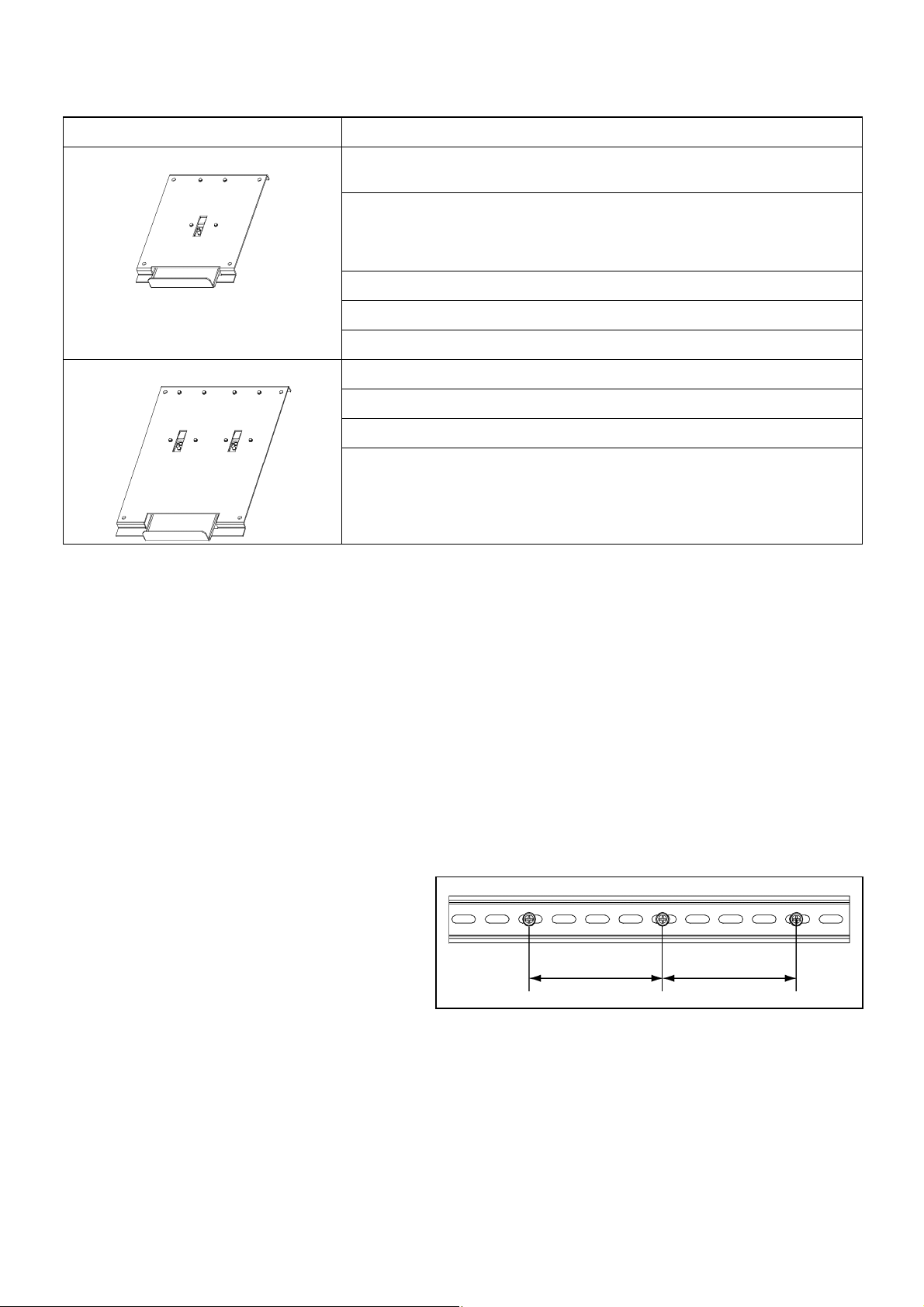
Rail Mounting Base Models Applicable Inverter Models
RMA-C1-2.2
RMA-C1-3.7
FRN002C1S-2U
FRN003C1S-2U
FRNF50C1S-4U
FRN001C1S-4U
FRN002C1S-4U
FRN003C1S-4U
FRN002C1S-7U
FRN001C1S-6U
FRN001C1E-7U
FRN005C1S-2U
FRN005C1S-4U
FRN003C1S-7U
3. Precautions on Usage
(1) In an environment where the FRENIC-Mini may be subjected to vibration or impact, the FRENIC-Mini installed to a din rail is
NOT recommended.
(2) Installation of the FRENIC-Mini with a rail mounting base is allowed only when the FRENIC-Mini is installed vertically.
(3) When installing the FRENIC-Mini series of inverters together with other devices on the same din rail, keep a space of at least 10
mm(0.4 in) between components. However, as long as you are installing the FRENIC-Mini series of inverters only and the ambient
temperature is 40ºC(104ºF) or below, side-by-side installation of the inverter without a gap is possible.
4. Installation Procedure
(1) Installing a rail
Secure a din rail (on which you want to set up your
FRENIC-Mini) with mounting screws at intervals of
a maximum of 200 mm(8 in) 100 mm(4 in) or less
recommended).
Max. 200 mm(8 in) Max. 200 mm(8 in)
- 2 -
Page 3

(2) Installation/Removal Procedure
A A
RMA-C1-0.75
Installing the rail mounting base to your FRENIC-Mini
1) As illustrated below, hold the rail mounting base with the arrow mark facing up. Press the rail mounting base against the
FRENIC-Mini straight so that the base's lower tabs "B" come to below the FRENIC-Mini's lower corners and tabs "A" beco me
fitted in the cutouts provided in the rear center of the FRENIC-Mini.
2) Slide up the rail mounting base along the back of the FRENIC-Mini. Make sure that the bosses provided on the rail mounting
base are fitted in the holes in the lower rear corners of the FRENIC-Mini.
rrow
mark
B
Installing the rail mounting base with the FRENIC-Mini to the din rail
1) Hook the upper latches of the rail mounting base over the upp er edge of the din rail.
2) Press the lower end of the FRENIC-Mini again st the din rail until the lower latches of the rail mounting base catch the din rail.
B
Figure 1
Boss on the rail mounting
base
Figure 2
Removing the rail mounting base with the FRENIC-Mini from the din rail
1) W hile holding the FRENIC-Mini by hand,
turn the handle of the rail mounting base clockwise or counterclockwise and pull the
lower end of the FRENIC-Mini towards you to release it from the lower latches of the rail.
CAUTION Be sure to support the FRENIC-Mini while removing. Failure to do so might allow the FRENIC-Mini to fall.
2) Lift up the FRENIC-Mini and release the rail mounting base and FRENIC- Mini fro m the din rail.
Handle
Figure 3
- 3 -
Page 4

RMA-C1-2.2/RMA-C1-3.7
Installing the rail mounting base to your FRENIC-Mini
1) As illustrated in Figure 4, set the FRENIC-Mini on the rail mounting
base with the FRENIC-Mini's bottom facing towards the handle.
2) Secure the FRENIC-Mini to the rail mounting base with four screws
(M4x12) that came with the rail mounting base.
Tightening torque: 1.8 N
m(0.74 lbfft)
Installing the rail mounting base with the FRENIC-Mini to the din rail
(See Figure 2.)
1) Hook the upper latches of the rail mounting base over the upper edge
of the din rail. The RMA-C1-3.7 has four upper latches, make sure that
all of the four latches catch the upper edge of the din rail.
2) Press the lower end of the FRENIC-Mini against the din rail until the
lower latches of the rail mounting base catch the din rail.
Removing the rail mounting base with the FRENIC-Mini from the din rail
(See Figure 3.)
1) W hile holding the FRENIC-Mini by hand,
pull down the handle of the
rail mounting base and pull the lower end of the FRENIC-Mini
towards you to release it from the lower latches of the din rail.
CAUTION Be sure to support the FRENIC-Mini while
removing. Failure to do so might allow the FRENIC-Mini to fall.
2) Lift up the FRENIC-Mini and release the rail mounting base and
FRENIC-Mini from the din rail.
M4x
12 screws
(that came with the mounting base)
Handle
Figure 4
Fuji Electric Systems Co., Ltd.
Fuji Electric Corp. of America
http://www.fujielectric.com/fecoa/
47520 Westinghouse Drive Fremont, CA 94539, U.S.A.
Tel.+1-510-440-1060 Fax.+1-510-440-1063
Toll-free support 1-888-900-FUJI(3854)
I NR-SI47-0774a-EU REV 052010 Information subject to change without notice.
- 4 -
 Loading...