

Page 1
Instruction Manual
FUZZY
CONTROLLER X
Type: PYX
PV
SV
SEL
OUT1
OUT2
ALM1
ALM2
INP-TN1PYXf-E
Page 2

Contents
I. PREPARING THE OPERATION ............................... 4
1. THE BASIC INSTALLATION PROCEDURE .................... 5
2. CHECK OF SPECIFICATIONS ........................................ 6
2.1 PYX4 MODEL CONFIGURATION ........................... 6
2.2 PYX5/9 MODEL CONFIGURATION ........................ 7
3. ACCESSORIES................................................................ 8
4. INSTALLATION ................................................................ 8
4.1 INSTALLATION PLACE ........................................... 8
4.2 INSTALLATION PROCEDURE ................................ 9
4.3 CAUTION ON SAFETY ............................................ 10
4.4 PANEL CUT DIMENSIONS ..................................... 18
5. WIRING ............................................................................ 19
5.1 PYX4 WIRING DIAGRAM
[When the output 1 is relay (SPST) output,
SSR drive output or current output].......................... 19
5.2 PYX4 WIRING DIAGRAM
[When the output 1 is relay (SPDT) output].............. 21
5.3 PYX5/9 WIRING DIAGRAM
(NOT UNIVERSAL OUTPUT) .................................. 23
5.4 PYX5/9 WIRING DIAGRAM
(UNIVERSAL OUTPUT) ........................................... 26
5.5 NOTES ..................................................................... 28
II. FRONT PANEL LAYOUT .......................................... 30
1
Page 3

III. OPERATION PROCEDURE ...................................... 33
1. OPERATION MODE/PARAMETER SETTING MODE ..... 33
2. VIEWING PARAMETERS ................................................ 33
3. CHANGING PARAMETERS............................................. 35
IV.SETTING INPUT AND OUTPUT TYPES .................. 37
Changing input ............................................................................. 37
Changing scale (voltage/current input) ......................................... 41
Changing output (universal output) .............................................. 42
V. FUNCTIONS .............................................................. 44
Lock .............................................................................................. 44
Auto-tuning ................................................................................... 47
Control function ............................................................................ 51
Alarm ............................................................................................ 55
Ramp soak ................................................................................... 60
Two set-points .............................................................................. 64
Analog output (AO) ....................................................................... 65
Digital output................................................................................. 67
Manual operation .......................................................................... 69
Remote SV ................................................................................... 71
Output monitoring ......................................................................... 72
VI.SET-UP PARAMETER .............................................. 73
Input filter ...................................................................................... 73
PV shift ......................................................................................... 74
Control type .................................................................................. 75
Output setting in input abnormal................................................... 76
Output limits.................................................................................. 77
Set point value limits..................................................................... 78
Output cycle time .......................................................................... 79
Direct/reverse control action......................................................... 81
2
Page 4

Control processing cycle time....................................................... 82
APPENDIX...................................................................... 83
1. ERROR MESSAGES........................................................ 83
2. POWER FAILURE ............................................................ 83
3. SPECIFICATIONS............................................................ 84
4. TROUBLESHOOTING...................................................... 89
5. PARAMETER LIST........................................................... 91
3
Page 5

I. PREPARING THE OPERATION
We thank you for the purchase of this PYX (Fuzzy Temperature
Controller).
Employing FUZZY LOGIC the PYX virtually eliminates system overshoot
and effectively suppresses fluctuation of the process variable due to
external disturbances.
Please read this manual, when programed and operated within the
guidelines setforth in this manual, your PYX controller will give you years of
precise, reliable control.
PYX
The product conforms to the requirements of the Electromagnetic compatibility Directive 89/336/EEC as detailed within the
technical construction file number TN510401. The applicable
standards used to demonstrate compliance are :
EN50081-1 : 1992 Conducted and Radiated emissions
EN50082-1 : 1992 Radiated immunity, ESD and FBT
(The unit meets Class A limits for Conducted Emissions.)
The unit also complies with the part of Immunity standards.
IEC1000-4-2 : 1995 level 3, IEC1000-4-3 : 1995 level 3
IEC1000-4-4 : 1995 level 3, IEC1000-4-8 : 1993 level 4
* E.U. indicates Engineering Units.
4
Page 6
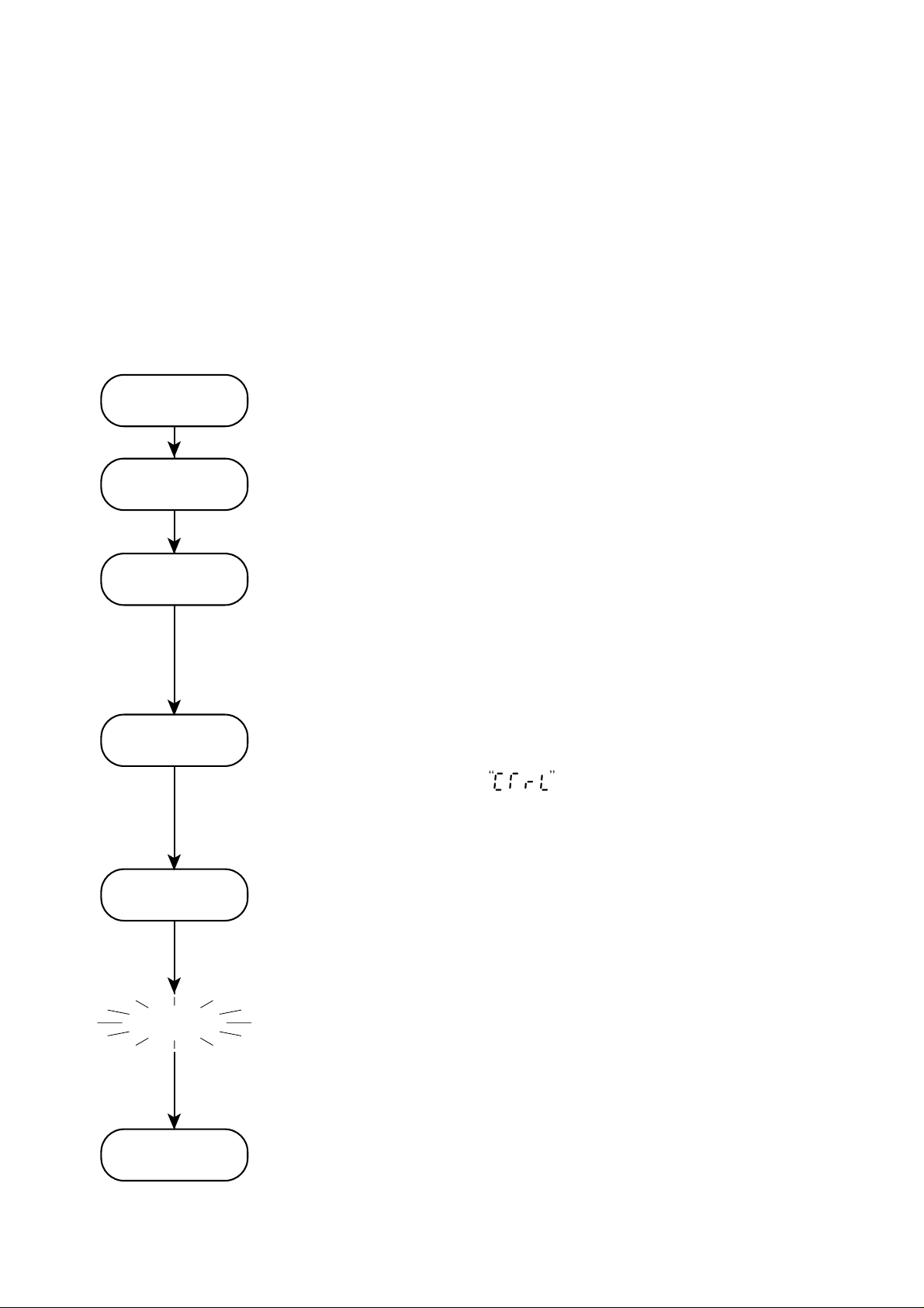
1. THE BASIC INSTALLATION PROCEDURE
Is given here as to the basic flow from the installation to operate the PYX.
For detailed description of each step, see the pages correspondent. See
the section “Operation Procedure” on the pages 33 to 36 for calls and
changes the specific parameter.
Installation of
Main Unit
Connection
Selecting Input
and Output Types
Selecting PID
or Fuzzy
Install the main unit on the panel, using the attached panel
mounting bracket. (See page 8 to 18 for details.)
Connect the unit to power supply and input and output
devices. (See page 19 to 29 for details)
Power up, then select and check input types (such as types
of sensors), input temperature range, decimal point used or
not used and so on. In case of the universal output type,
set and check the output switch pins inside the main unit.
(See page 37 to 43 for details.)
Either the conventional PID control mode or the fuzzy
control mode, which is effective in minimizing overshoot
rate and outer condition effects, can be selected. Select by
setting the parameter , where the default set is PID.
(See page 75 for details.)
Tuning
Ready
Normal
Operation
System power up then, execute auto-tuning to define the
control parameters. (See page 47 to 50 for details.)
Basic preparations are completed. Carry on settings for the
optional functions (alarm, two set points, transmission,
ramp soak, analog output etc.), following this instruction.
See page 44, as setting values (SV) can be set in the same
manner as the Lock parameter on page 44.
5
Page 7
2. CHECK OF SPECIFICATIONS
Please make sure that specifications of this product is according with
your request. The product specifications are provided on the main unit
as model configuration following.
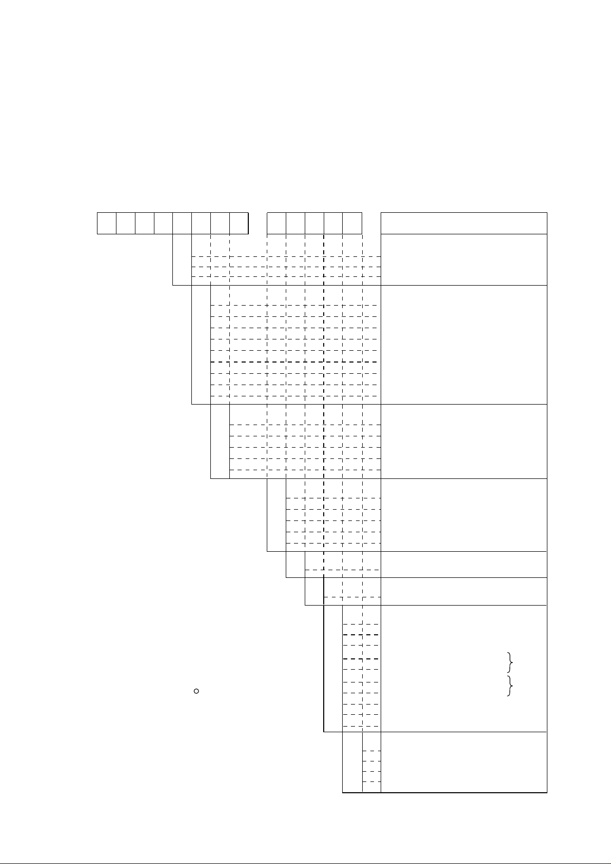
2.1 PYX4 MODEL CONFIGURATION
12345678 910111213
PYX
4 1-
T
A
M
Y
A
B
C
D
E
F
G
H
Y
A
B
C
D
0
1
2
3
4
*
Note 1: Fuji Electric CC data line protocol
Note 2: Modbus RTU protocol
R
Contents
Input type
TC/PT input
Voltage/Current input
TC/PT/Voltage/Current multi input
Control output1
Without
Relay (SPST) rev. act.
Relay (SPST) dir. act.
SSR drive rev. act.
SSR drive dir. act.
Current (DC 4~20mA) rev. act.
Current (DC 4~20mA) dir. act.
Relay (SPDT) rev. act.
Relay (SPDT) dir. act.
Control output2
Without
Relay (SPST) rev. act.
Relay (SPST) dir. act.
SSR drive rev. act.
SSR dirve dir. act.
Alarm function
Without
1pt.
2pts.
HB alarm
HB alarm + 1pt.
Input type code
See Page 21.
Input range code
*
Y
P
Q
R
S
M
N
A
B
C
J
E
F
K
See Page 21.
Additional function
Without
2 set points
4 ramp soak with start/reset
RS-485 transmission
RS-485 transmission
RS-485 transmission
RS-485 transmission + 4 ramp soak
Auxiliary analog output
Auxiliary analog output + 4 ramp soak
Remote SV
Front panel
Japanese
English (
°
C)
English (
°
F)
English (%)
+ 4 ramp soak
Note 1
Note 2
6
Page 8
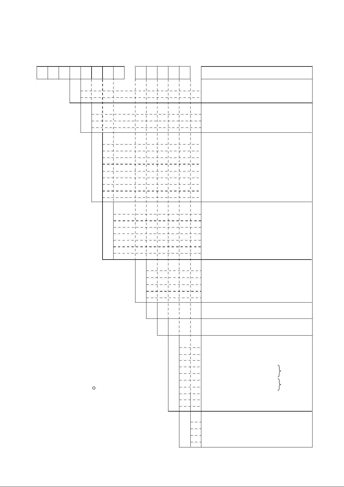
2.2 PYX5/9 MODEL CONFIGURATION
12345678 910111213
PYX
5
9
M
1-
Front panel dimensions:
48×96 mm
96×96 mm
Input type
T
A
Y
C
D
E
F
G
H
J
K
Y
C
D
E
F
G
H
0
1
2
3
4
TC/Pt input
Voltage/Current input
TC/Pt/Voltage/Current multi-input
Control output 1
Without
SSR/SSC drive rev. act.
SSR/SSC drive dir. act.
Current (DC4-20mA) rev. act.
Current (DC4-20mA) dir. act.
Relay rev. act. (SPDT)
Relay dir. act. (SPDT)
Universal output rev. act.
Universal output dir. act.
Control output 2
Without
SSR drive rev. act.
SSR drive dir. act.
Current (DC4-20mA) rev. act.
Current (DC4-20mA) dir. act.
Relay rev. act. (SPDT)
Relay rev. dir. (SPDT)
Alarm function
Without
1pt.
2pts.
HB alarm
HB alarm + 1pt.
Contents
*
*
Y
P
Q
R
S
Note 1: Fuji Electric CC data line protocol
Note 2: Modbus RTU protocol
R
M
N
A
B
C
7
Input type code
See Page 21.
Input range code
See Page 21.
Additional functions
Without
2 set points
4 ramp soak with start/reset
RS-485 transmission
RS-485 transmission + 4 ramp soak
RS-485 transmission
RS-485 transmission + 4 ramp soak
Auxiliary analog output
Auxiliary analog output + 4 ramp soak
Remote SV
Front panel
J
E
F
K
Japanese
English (
English (°F)
English (%)
°
C)
Note 1
Note 2
Page 9

3. ACCESSORIES
In addition to the main unit, the following accessories are shipping in
the same package.
Accessories Quat.
Instruction manual (this manual) (INP-TN1PYX-E)
Panel mounting bracket set
Current input resistance (250Ω)
* Not delivered for TC/PT input type
* Suffix means revision control
4. INSTALLATION
4.1 INSTALLATION PLACE
Please verify if where the controller is mounted there is no:
(1) splash of water,
(2) mechanical vibration,
1
1
1
(3) extreme temperature
(4) no corrosive gases,
(5) dust or oil smoke,
(6) electric noise.
8
Page 10
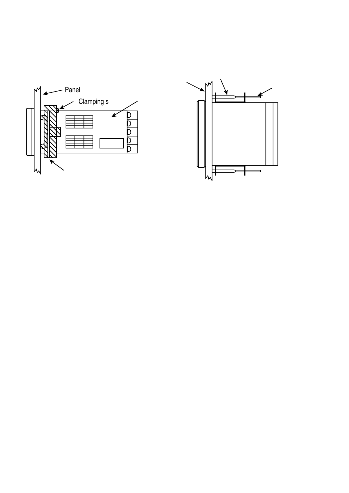
4.2 INSTALLATION PROCEDURE
;
Panel mounting bracket (accessorie)
Panel
Panel
Clamping screw Main unit
Panel mounting bracket (accessorie)
Clamping screw
For PYX4
For PYX5/9
• For PYX4
Slide the enclosed plastic panel mounting bracket (shipped with
every PYX4) up the back of the controller until it makes contact
with the back of the panel. Push the mounting bracket until the
tabs seat themselves in the molded tab ridges, located on the
front of the controller’s outer case. Tighten the two screw on the
mounting bracket for added pressure; do not use excessive
force.
• For PYX5/9
The mounting bracket’s tabs fit into the two holes on both the top
and bottom of the controller’s outer case. With an instrument
screwdriver, turn the screw in the mounting bracket until the end
of it touches the back of the panel. Do this to both brackets.
Making sure that the face of the controller is flush and straight,
tighten both mounting bracket screws. Your controller should
now be firmly set. If the controller is still loose, tighten the
mounting bracket screw a little more. Do not use excessive
force.
9
Page 11
4.3 CAUTION ON SAFETY
First of all, read this "Caution on Safety" carefully,
and then use the instrument in the correct way.
The cautionary descriptions listed here contain important information about
safety, so they should always be observed. Those safety precautions are
classified in 2 ranks, WARNING and CAUTION.
The following shows the meaning of WARNING and CAUTION.
Wrong handling may cause a dangerous situation,
WARNING
CAUTION
1. WARNING
1.1 Caution on wiring
1) For the safe operation of the controller, where the temperature probe is to
be installed into an environment where voltage exceed 50VDC, it is essential that reinforced isolation or basic isolation and earth the maintained between all connections to the rear of the temperature controller, and that
supplementary isolation is required for the alarm outputs.
in which there is a possibility of death or heavy
injury.
Wrong handling may cause a dangerous situation,
in which there is a possibility of injury or physical
damage.
The outputs from the controller are all less than 50VDC.
When wiring the power supply terminal, use vinyl insulated 600 volt cable
or equivalent. A switch breaking both poles of the mains supply should be
installed together with a fuse with a rating of 250 volt 1 Amp. The fuse
should be installed between the mains switch and the controller.
The level of insulation provided by the temperature controller is:-
MAIN = BASIC
HEATER = BASIC
INPUTS = BASIC
10
Page 12
Prior to operation of the installed system the wiring should be checked to
ensure that the required levels of insulation have been provided.
2) When a fault in the instrument is likely to lead to a serious trouble, use a
suitable protective circuit on the outside for protection against trouble.
3) This unit is not provided with power switch, fuse, etc. These parts can be
installed separately, if required (fuse rating; 250V, 1A).
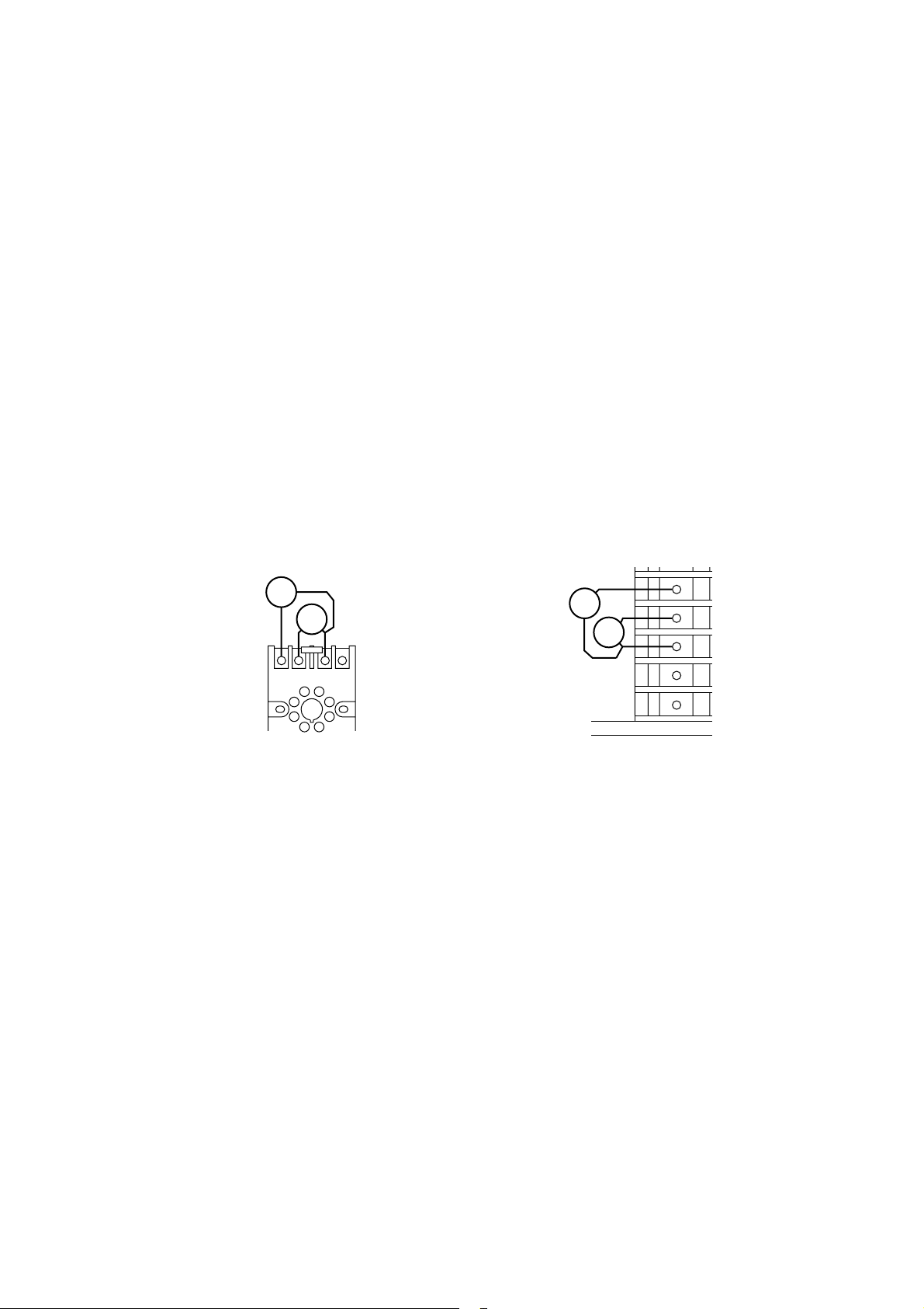
4) Use of Fuji's Z-Trap is recommended to protect the relay output from switching surge and to ensure a long life.
Type: ENC241D - 05A (power voltage; 100V)
ENC471D - 05A (power voltage; 200V)
Mounting position: Connected to relay control output terminals
ex) PYZ4
Socket (ATX2PSB)
65 43
1.2 Operating condition
Operating temperature : -10 to 50°C
Operating humidity : 90%RH or less (non condensing)
Installation category :
Pollution degree : 2
PYZ9
5
6
7
8
9
Ⅱ
1.3 Power source
1) Use a power source of rated voltage to prevent damage or trouble.
2) Do not turn ON the power until the wiring is completed to prevent shock
hazard or trouble.
11
Page 13

1.4 Prohibition of use in gas
The instrument is not an intrinsic safety explosion - proof type. Do not use
it in a place exposed to combustible or explosive gas.
1.5 Contact to unit
1) This unit must not be disassembled, modified or repaired to prevent malfunction, shock hazard or fire accident.
2) When the power is ON, do not touch the terminals to prevent shock hazard
or malfunction.
1.6 Caution on maintenance
1) Before mounting or removing the module or unit, turn OFF the power in
advance to prevent shock hazard, malfunction or trouble.
2) Periodical maintenance is recommended to ensure continuous and safe
operation of the instrument. Some parts of the instrument are limited in life
or are subject to secular change.
WARNING
It is essential that, when the controller is introduced into a system
which uses or generates a hazardous voltage, the minimum creepage
and clearances specified in the table below are maintained on the
temperature probe. A hazardous voltage is one that exceeds 42.4V
peak AC or 60V DC. If you have any doubt, seek advice from a
competent engineer before installing the controller into the host
equipment.
The equipment must be installed such that with the exception of the
connection to the mains, creepage and clearance distances shown in
the table below are maintained between the temperature probe and
any other assemblies which use or generate a voltage shown in the
12
Page 14
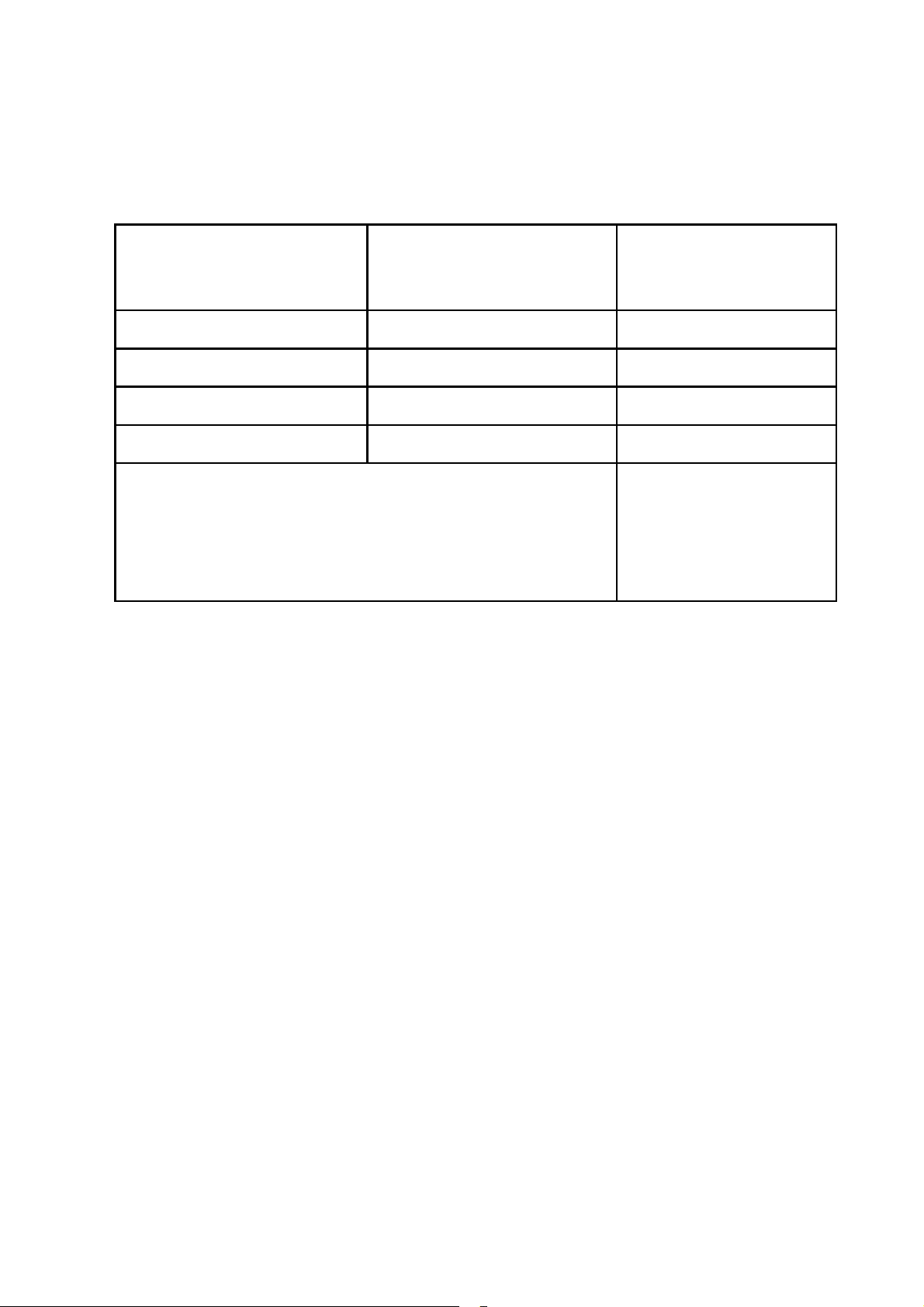
table below. Failure to maintain these minimum distances would
Clearance (mm) Creepage (mm) Voltage used or generated
by the other assemblies
0.2 1.2 Up to 50V
rms or V DC
0.2 1.4 Up to 100Vrms or V DC
0.5 1.6 Up to 150Vrms or V DC
1.5 3.0 Up to 300Vrms or V DC
Above 300Vrms or V DC
For a host or other assemblies fitted in the system, using or
generating voltages greater than 300V(rms or DC),advice from
a competent engineer must be obtained before installation of
the relevant equipment.
invalidate the EN61010 safety approval.
It is essential that following the installation of the system, and prior to
powering the system up that it is tested to determine that the correct
level of isolation is present to protect the user and other equipment
against the hazards of electric shock and fire.
An explanation of creepage and clearance is given in the following
diagram.
13
Page 15
EXAMPLE INSTALLATION DIAGRAM
TO MAINTAIN SAFETY OF CONTROLLER
Example of how to install Controller into an environment where
hazardous voltages may exist is shown below.
Make sure installed system
has basic insulation around
Thermocouple, RTD,
Voltage or Current
Make sure
installed
system has
basic
insulation
Heater Break
Circuit
this connection
24V mains
supply
Controller
Example Diagram To Explain The Meaning Of Creepage and
Clearance Distances Is Shown Below
Communication card
X
X
Y
Y
Expansion card
Except for the edge connector which
plugs into the host's expansion slot,
clearance distance (X mm) and
creepage distance (Y mm) as given in
the table above, must be maintained
between the controller and any other
assemblies which use or generate a
hazardous voltage.
14
Page 16

2.
CAUTION
2.1 Caution on handling
1) Do not install the unit in any of the following places.
• A place where the ambient temperature exceeds the range of -10
50°C
• A place where the ambient humidity exceeds 90%RH
• A place where temperature changes suddenly or dew condensation
occurs
• A place exposed to corrosive gases (sulfuric gas, ammonia, etc.) or
combustible gases
• A place where vibration or shock is likely to be directly transmitted to
the body.
• A place exposed to water, oil, chemicals, vapor, steam, etc.
• A place with much dust, salt or iron component
• A place with much inductive disturbance, static electricity, magnetism
or noise
〜
• A place exposed to direct sunlight
• A place where heat such as radiant heat stays
2) Mounting
• PYX5/9
For mounting, attach the supplied mounting brackets (2 units) on top
and bottom and tighten with a screwdriver. Tightening torque is about
147N.cm (1.5kg.cm). (The case is made of plastic. Care should be
taken not to tighten forcedly)
15
Page 17

• PYX4
Insert the supplied mounting frame from the rear side and push it in
until the main unit is secured firmly to the panel. If it has a slight play,
tighten the 2 screws until the play is eliminated. (If the screws are tightened forcedly, the mounting frame may be slipped off the stopper)
3) When the unit is exposed to water, it may lead to a short-circuit or fire
hazard. Contact your dealer for inspection.
2.2 Caution on cable connection
1) For thermocouple input, use a suitable compensating cable.
2) For resistance bulb input, use a cable with a small lead wire resistance and
without resistance difference between 3 wires.
3) When external wiring has much noise, use the following step. When a
conducted as load of digital output such as relay contact output or alarm
output, connect a surge absorber to the conductor coil. (Example:
ENC471D-05A for 200V AC)
4) When the power source has much noise, use an insulating transformer
together with a noise filter. Noise filter should be mounted on a panel which
has been earthed. The wiring between the noise filter output and the instrument power terminals should be as short as possible. Do not connect a
fuse or switch to the noise filter output wiring, as it affects the performance
of the filter.
5) Use of a twisted cable for the instrument power source provides better effects (short twist pitch is effective for noise).
6) When a heater burnout alarm is provided, the heater power and controller
power should be connected using the same power line.
7) Time for preparation of contact output is required at power ON. When the
output signal is used for an external interlock circuit, etc., connect a delay
relay to the circuit.
16
Page 18

2.3 Other
When cleaning the instrument, do not use organic solvents such as alcohol,
benzine, etc. Use neutral detergent.
3. Caution on key operation / trouble
(1) Alarm function should be set correctly. Otherwise, alarm output
cannot be obtained at the time of occurrence of trouble. Be sure to
check the function prior to operation.
(2) Do not stop the device forcedly during auto - tuning, as it affects the
control action. When it needs to stop forcedly, be sure to turn OFF
the power in advance.
(3) If the input cable is disconnected, the display shows UUUU or LLLL.
When replacing the sensor, be sure to turn OFF the power.
17
Page 19
4.4 PANEL CUT DIMENSIONS
65 or more
100 or more
65
or more
45
+0.5
-0
+0.5
45
-0
For PYX4
92
+0.8
-0
+0.8
92
-0
For PYX9
When mounting one unit When mounting multiple n units (2
45
+0.8
-0
+0.8
a
-0
≤
n ≤ 6)
115
or more
92
+0.8
-0
+0.8
92
-0
For PYX5
18
Unitsa2
933141418952376285
Units (mm)
Page 20
5. WIRING
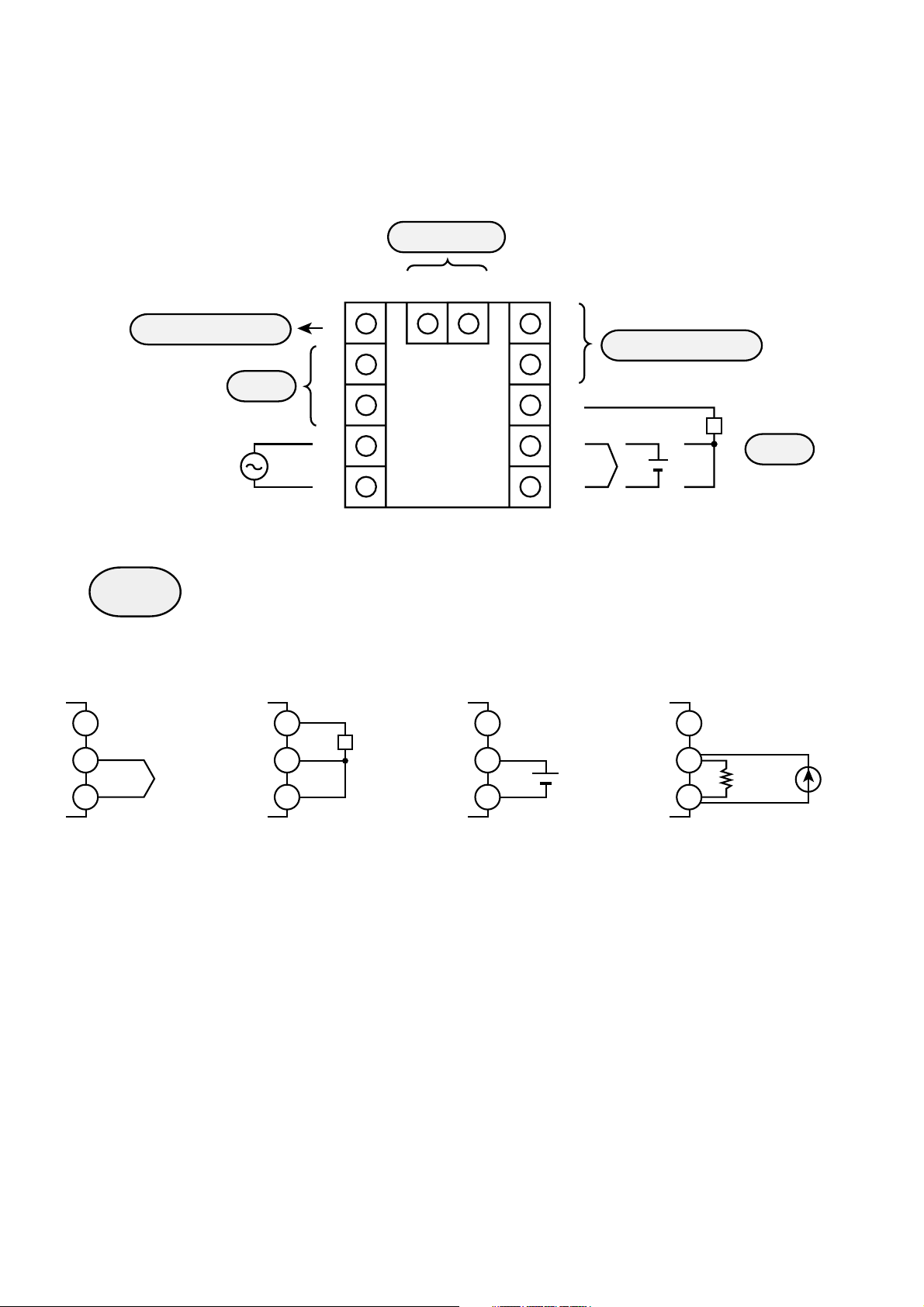
5.1 PYX4 WIRING DIAGRAM
[When the output 1 is relay (SPST) output, SSR drive output or
current output]
Option
11 12
6
7
8
9
10
Control output 1
+
–
+
AC100-240V
50/60H
z
Alarm
1
2
3
4
5
Input
TC input Pt input Voltage input
N.C. N.C. N.C.
8
9
10
8
+
–
9
10
Pt
8
9
10
+
Pt
Input
Current input
8
9
250Ω
10
+
NOTE: • For current input (4-20mA), use the accessorie
Ω
resistance (250
).
• Make sure that the setting pin is in the appropriate
position according to page 40.
19
Page 21
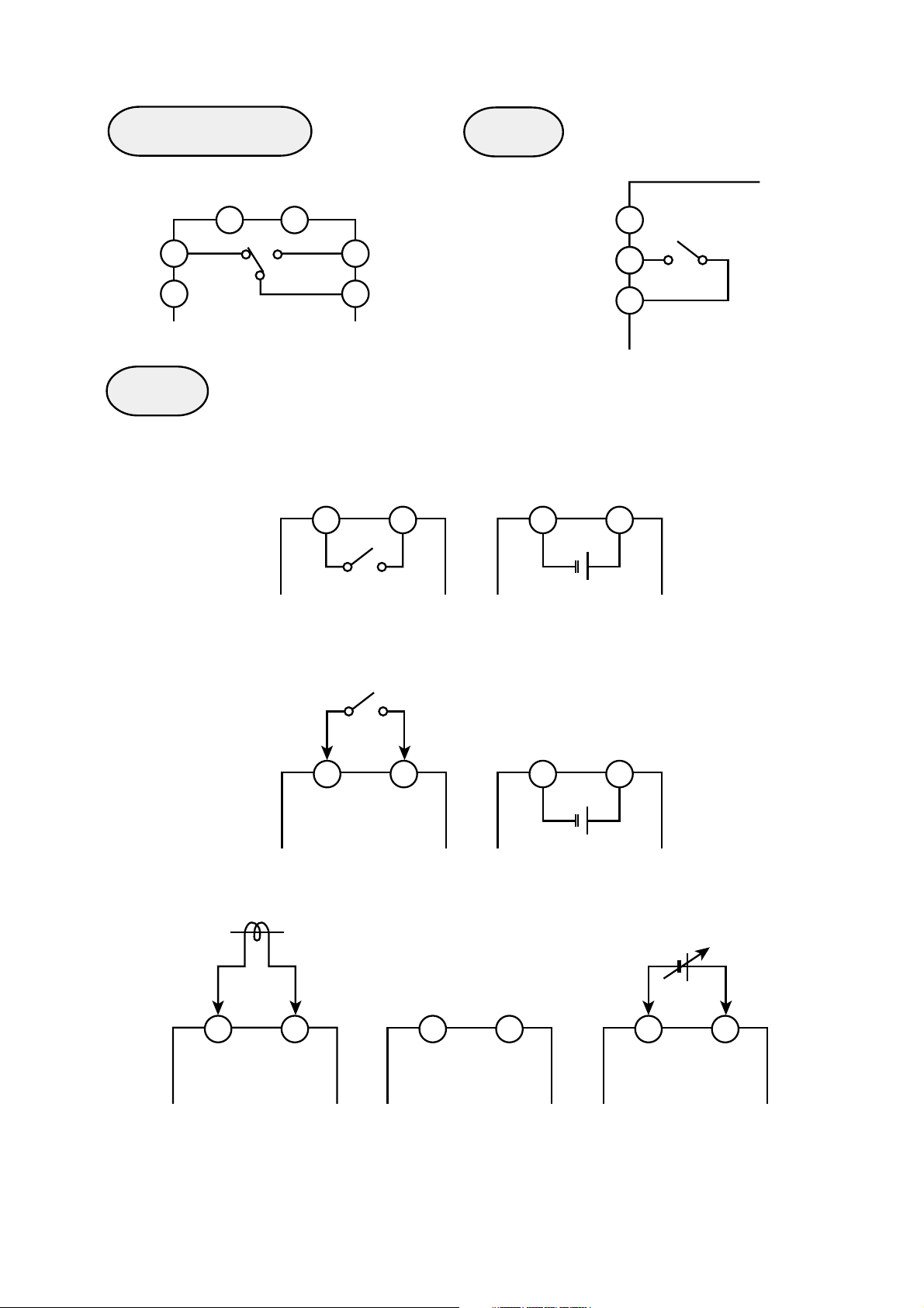
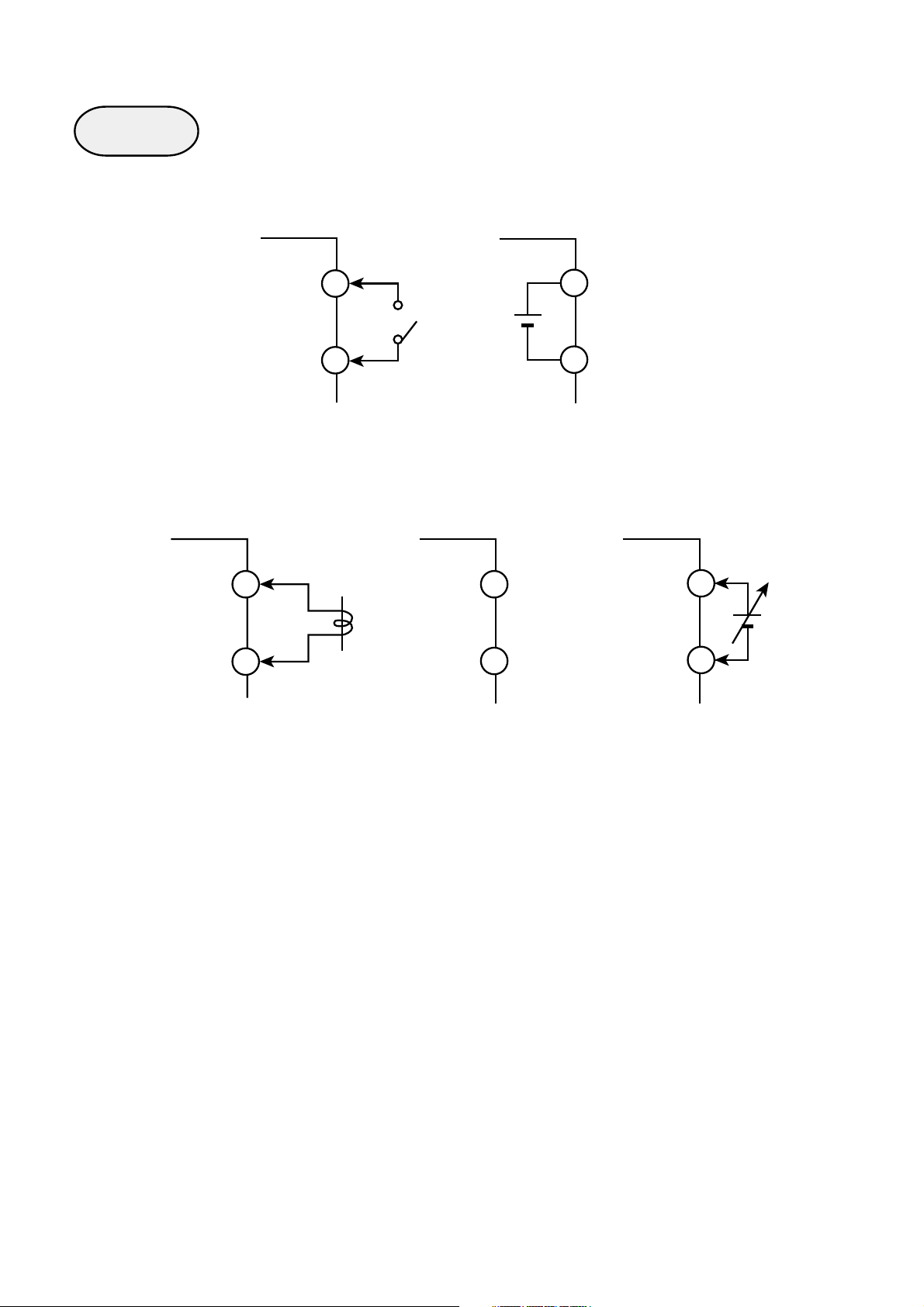
Control output 1
For relay output For SSR drive output For current output
Alarm
ALM2
ALM1
ALM-COM
Option
6
++
7
1
2
6
DC-V DC 4-20mA
7
6
7
NOTE: Only ALM 1 is available in the case of
3
the digital output type.
For control output 2
(relay output)
11
For current transformer input For RS485 transmission
11 12
12 11 12
For control output 2
(SSR drive output)
+
TRX– TRX+
11 12
For digital input
11 12
For remote SV input
+
11 12
For AO output
11 12
+
20
Page 22
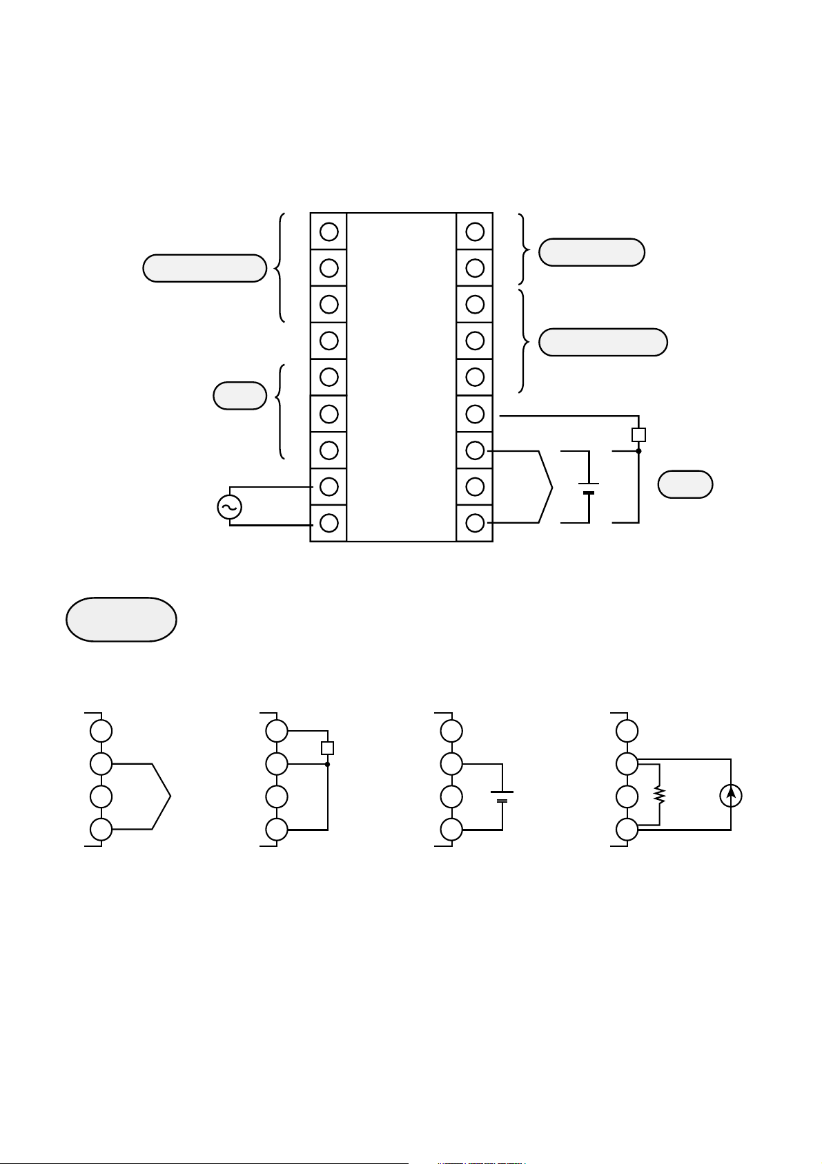
5.2 PYX4 WIRING DIAGRAM
[When the output 1 is relay (SPDT) output]
Option
11 12
Control output 1
AC100-240V
50/60H
z
1
2
Alarm
3
4
5
6
7
8
9
10
Control output 1
+
+
–
–
Input
TC input Pt input Voltage input
N.C. N.C. N.C.
8
9
10
8
+
–
9
10
Pt
10
8
9
+
Pt
Current input
8
9
250Ω
10
Input
+
NOTE: • For current input (4-20mA), use the accessorie
Ω
resistance (250
).
• Make sure that the setting pin is in the appropriate
position according to page 40.
21
Page 23
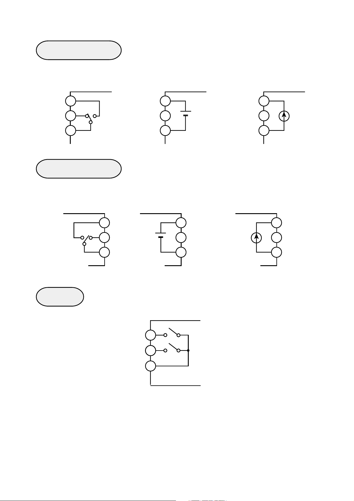
Control output 1 Alarm
N.C. N.O.
1
2
Option
11 12
For control output 2
6
7
(relay output)
11
For digital input
12 11 12
1
ALM
ALM-COM
For control output 2
(SSR drive output)
For AO output
2
3
+
11 12
For current transformer input For RS485 transmission
TRX– TRX+
11 12
11 12
11 12
+
For remote SV input
+
11 12
22
Page 24
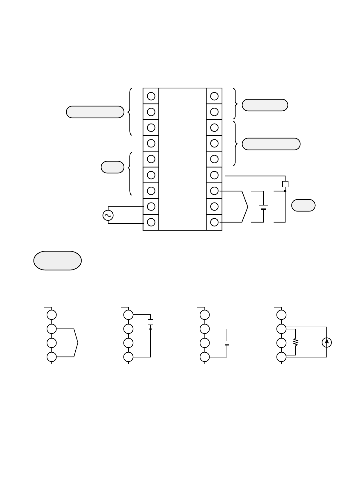
5.3 PYX5/9 WIRING DIAGRAM
(Not universal output)
Control output 1
AC100~240V
50/60H
z
Output
Alarm
1
2
3
4
5
6
7
8
9
10
11
12
13
14
15
16
18
Option
Control output 2
Pt
+
+
Input
–
For TC input For Pt input For voltage input For current input
15
N.C. N.C. N.C.
+
16
–
18
15
16
18
Pt
15
16
18
15
16
+
250Ω
18
NOTE: • For current input (4-20mA), use the accessorie
Ω
resistance (250
).
• In the case of multi-input, make sure that the setting
pin is in the appropriate position according to page
40.
+
23
Page 25
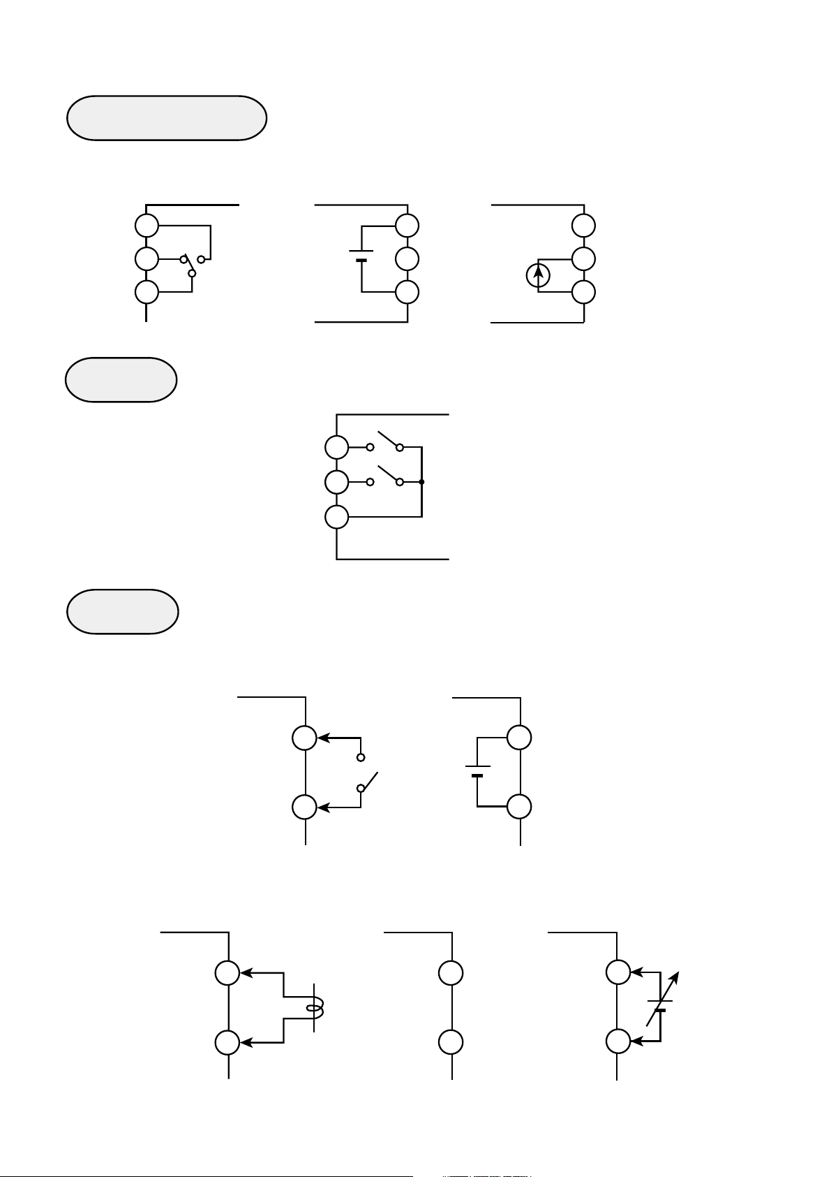
Control output 1
For relay output For SSR drive output For current output
N.O.
1
N.C.
2
1
++
DC-V DC 4-20mA
2
1
2
3
3
Control output 2
For relay output For SSR drive output For current output
N.O.
N.C.
12
+
13
14
12
+
13
DC-V DC 4-20mA
14
Alarm
3
12
13
14
ALM1
ALM2
ALM-COM
5
6
7
24
Page 26
Option
For digital input
10
11
For AO output
+
For current transformer input For RS485 transmission
10 10
TRX+
10
11
For remote SV input
+
10
11
11
TRX–
11
25
Page 27
5.4 PYX5/9 WIRING DIAGRAM
(universal output)
Control output 1
AC100~240V
50/60H
z
Input
Alarm
1
2
3
4
5
6
7
8
9
10
11
12
13
14
15
16
18
Option
Control output 1
Pt
+
+
Input
–
For TC input For Pt input For voltage input For current input
15
N.C. N.C. N.C.
+
16
–
18
15
16
18
Pt
15
16
18
15
16
+
250Ω
18
NOTE: • For current input (4-20mA), use the accessorie
Ω
resistance (250
).
• In the case of multi-input, make sure that the setting
pin is in the appropriate position according to page
40.
+
26
Page 28
Control output 1
For relay output For SSR drive output For current output
1
2
3
Alarm
Option
N.O.
N.C.
ALM1
ALM2
ALM-COM
12
+
13
DC-V DC 4-20mA
14
5
6
7
12
13
+
14
For digital input
10
11
For AO output
+
For current transformer input For RS485 transmission
10 10
11
11
TRX+
TRX–
10
11
For remote SV input
+
10
11
27
Page 29

5.5 NOTES
Connection:
• No power switch and fuse are provided on this product. Install
them separately if necessary.
• Use designated compensating wire in the case of thermocouple input.
• Use wire with line resistance lower that 10
thermoresistance input.
• To avoid noise induction to input wires separate from the
power and output wires also connected to your controller.
• In case of model equipped with heater break alarms, the
power supply used should be the same for the PYX and
Heater.
Ω
for
• Use shielded wires for input wires. Keep them away from
output wires.
Noise:
Take the following measures when there is serious noise
induction in the external wiring:
• When using a contactor as a load on digital output such as
relay contact output and alarm output, supplement a serge
absorber to the coil side of the contactor.
Z-Trap (ENB461D-14A for AC220V) manufactured by Fuji
Electric
• In the case of noise induction from the power supply, the use
of an insulated transformer and a noise filter is recommended.
Noise Filter (ZMB22R5-11) manufactured by TDK
• It is efficacious against noise induction to twist the power
wires.
28
Page 30

Connection of Load Circuit:
• When the frequency of operation is rather high, in the case of
proportional operation for instance, maximum load with
respect to the capacity of the output relay will result in shorter
life. Use an auxiliary relay in such a case. Type SSR is
recommended.
electromagnetic switch: proportion cycle 20 sec. and above
SSR: proportion cycle 2 sec. and above
(approximately)
contact output life: mechanical: 10 million times (no load)
electrical: 100 thousand times (nominal
load)
• Relay contacts will be worn out with time. After certain period
has passed, locking (a phenomenon in which a contact cannot
be released once switched on) may happen. It is advisable to
provide an external safety device to protect the system just in
case locking happens.
29
Page 31

II. FRONT PANEL LAYOUT
➀
PV value display
➁
Set point value display
➀
➁
PV
SV
SEL
OUT1
➂
OUT2
➃
ALM 1
➄
ALM 2
➅
➂
Control output 1 monitor lamp
➃
Control output 2 or remote operation monitor lamp
➄
Alarm 1 lamp
➅
Alarm 2 lamp
➆
SELECT/Registration
➇
DOWN key
➈
UP key
➀
➁
➆
➉
➆➇➈➉
➉
CARRIAGE/Registration
PYX4
➂
➃ ➄ ➅
OUT1
OUT2 ALM 1 ALM 2 OUT1 OUT2 ALM 1 ALM 2
PV
➀
SV
➁
SEL
➈
➇
PYX-5
➂➃➄➅
PV
SV
SEL
➆➇➈➉
PYX-9
PYX5
PYX9
30
Page 32

➀
PV value display
PV Displays the measured value, as well as
the failure information. When more than
one failure occurs simultaneously, the
failure information of the highest priority
alone will be displayed.
➁
Set point value display
Display Priority
Main unit failure
Heater disconnected
Control loop failure
Meaning
High
Low
SV Displays the set point value.
(During auto-tuning or manual operation,
the display of
or
and set point value alternate.)
➂
Control output-1 monitor lamp
Output 1(OUT1) Lights when Output 1 is ON. (it does not
●
➃
Control output 2 or remote operation monitor lamp
●
light for the current output type.)
This lamp lights when Output 2 is ON or
during remote operation. (it does not
light for the single output type.)
Dual Control type
Output 2(OUT2) Acts as the control output 2 monitor lamp.
●
Remote SV type
REM Acts as the remote operation monitor lamp.
●
31
Page 33

➄
Alarm-1 monitor lamp
ALM 1 Lights when the alarm-1 relay operates
●
➅
Alarm 2 monitor lamp
ALM 2 Lights when the alarm-2 relay operates
●
➆
SELECT/Registration
Used to switch from the operation mode
SEL
to parameter setting mode, to select
parameters, and to Registration set
values.
Keeping pressing this key for about 3
➇
DOWN key
➈
UP key
sec switches between the operation
mode and parameter setting mode.
Used to select parameters and to
decrease set values.
Continuing to press this key results in
auto-repeat.
Used to select parameters and to
increase set values.
Continuing to press this key results in
auto-repeat.
➉
CARRIAGE/Registration
Used for preset value digit carrying or for
preset value Registration.
32
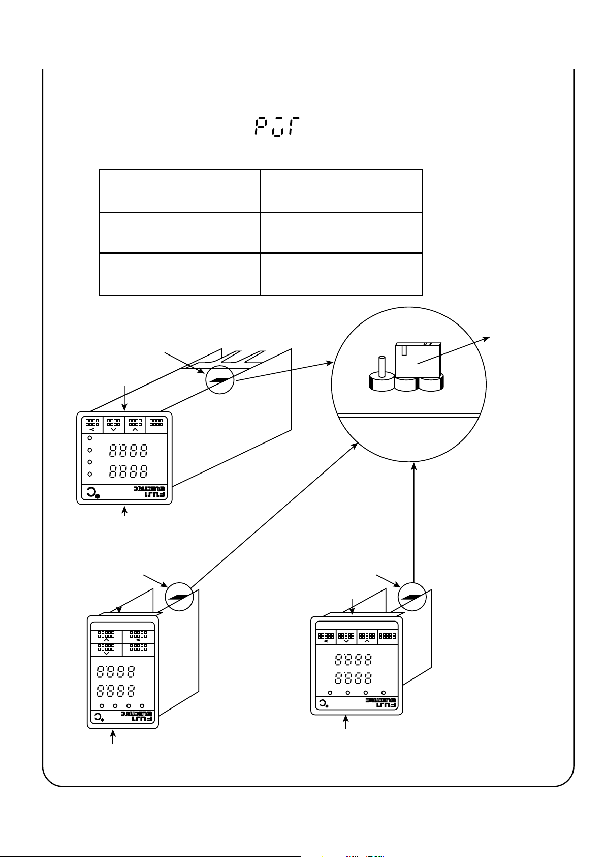
Page 34

III. OPERATION PROCEDURE
1. OPERATION MODE/PARAMETER SETTING MODE
The operation of this device includes the Operation Mode where
measured and set values are displayed and the Parameter Setting
Mode where various parameters are set.
To switch between the operation and parameter setting modes,
SEL
continue to press the
key for about 3 sec.
Continue to press
Operation Mode Parameter Setting Mode
Displays measured and set
point.
Displays information on loop*
break, heater break
error, auto-tuning, and manual
operation.
Changes set point.
*
, main-unit
SEL
key for about 3 sec
Make no operation
for 1 min
Displays and changes
various parameters.
*
indicates an option.
2. VIEWING PARAMETERS
1. Enter the parameter setting mode. (continue to press
SEL
key for
about 3 sec)
SEL
2. Display the target parameter with the
, , or key.
NOTES: No parameter is displayed if its parameter lock setting is
illegal or if its corresponding option has been mounted in the
system.
33
Page 35

PV
SV
PV
* The numeric value shown in the
left-hand figure is only an example.
Continue to
press
SEL
key for about
3 sec
SEL
Parameter Setting Mode Operation Mode
SEL
SV
parameter
or
PV
SV
parameter
or
•
•
•
•
SEL
or
PV
SV
parameter
*Not displayed unless the transmission option is provided.
34
Page 36

3. CHANGING PARAMETERS
1. Display the parameter to be set (to be changed) on the screen, as
described in the Section 2. “Viewing Parameter” (page 33).
2. Select the digit to be set (to be changed ), with the
key (the
selected digit flickers).
3. Set (to be changed ) the data with the
SEL
4. Press the
key, or repeat pressing the key until it stops
and keys.
flickering (the set (changed) data is registered).
NOTES: If no operation is made for about one minute during data
setting (changing), control automatically returns to the
operation mode. The data being changed (set) at this time is
invalidated.
35
Page 37

Example
<<Changing “Lock” from 1 to 2>>
PV
SV
Display the target
➀➁➂
Press
parameter.
PV
SV
The leftmost digit
flickers, and data of that
digit is changeable.
PV
SV
The center right digit
➃➄
flickers, and data of that
digit is changeable.
PV
SV
The center left digit
flickers, and data of that
digit is changeable.
PV
SV
The rightmost digit
flickers, and data of that
digit is changeable.
PV
SV
Increment data by 1 to 2. Flickering stops, and is the
➅➆
SEL
or
PV
SV
registered.
36
Page 38

IV. SETTING INPUT AND OUTPUT TYPES
After completing wiring, make sure that the measured value is of the right
type before operating the device.
Parameter to be used
Changing input
Setting the Input type ( )
It refers to setting the input type (range), presence or absence of decimal-
°C/°
point, and units of display (
Setting procedure
F).
PV
SV
PV
SV
1. Turn the power of PYX
(LEDs go on after a few sec).
SEL
2. Continue to press the key for about 3 sec (parameter
is displayed).
At that time, if is displayed steps 3 and 4 need not
be executed.
3. Press the key 4 times (the right most digit flickers).
37
Page 39

PV
SV
PV
SV
PV
4. Change the lower display to with the
and keys, and stop flickering and
register the value with the and keys.
SEL
5. Repeat pressing the key until parameter
is displayed.
SV
6. Set parameter to the desired specifications
following.
Example: Setting of K thermocouple for 0.0-400.0 °C range
Display unit
0
°
C display
1
°
F display
Decimal-point display
0
No decimal point
0.1
1
°C/°
F display
Input type code
38
Page 40

Input signal and measurement range
Input signal
Thermoresistance
JIS
Thermoresistance
old JIS
Thermocouple
Pt100
Pt100
Pt100
Pt100
Pt100
Pt100
Pt100
Pt100
JPt100
JPt100
JPt100
JPt100
JPt100
JPt100
JPt100
J
J
K
K
K
R
B
T
T
E
E
S
N
U
WRe5-26
PL-II
Input type
code
00
01
02
03
04
05
06
07
10
11
12
13
14
15
16
20
21
22
23
24
25
26
27
28
29
2A
2B
2C
2D
2E
2F
Measurement
range (°C)
0~150°C
0~300°C
0~500°C
0~600°C
–
50~100°C
–
100~200°C
–150~600°C
–150~850°C
0~150°C
0~300°C
0~500°C
0~600°C
–
50~100°C
–
100~200°C
–150~600°C
0~400°C
0~800°C
0~400°C
0~800°C
0~1200°C
0~1600°C
0~1800°C
–199.9~200°C
–
150~400°C
0~800°C
–199.9~800°C
0~1600°C
0~1300°C
–199.9~400°C
0~2300°C
0~1300°C
Measurement
°
range (
–
–
238~1112°F
–
238~1562°F
–
–
238~1112°F
–
–
–
328~1472°F
–
F)
32~302°F
32~572°F
32~932°F
32~1112°F
–
58~212°F
148~392°F
32~302°F
32~572°F
32~932°F
32~1112°F
–
58~212°F
148~392°F
32~752°F
32~1472°F
32~752°F
32~1472°F
32~2192°F
32~2912°F
32~3272°F
328~392°F
238~752°F
32~1472°F
32~2912°F
32~2372°F
328~752°F
32~4172°F
32~2372°F
0.1°C
display
Ο
Ο
Ο
Ο
Ο
Ο
Ο
Ο
Ο
Ο
Ο
Ο
Ο
Ο
Ο
Ο
Ο
Ο
Ο
×
×
×
Ο
Ο
Ο
Ο
×
×
Ο
×
×
0.1°F
display
Ο
Ο
Ο
×
Ο
Ο
×
×
Ο
Ο
Ο
×
Ο
Ο
×
Ο
×
Ο
×
×
×
×
×
×
×
×
×
×
×
×
×
Power
supply
voltage
Power
supply
current
NOTES:
DC1-5V
DC0-5V
40
41
–1999
(Possible scaling range)
to
9999
Ο: Enabled
×: Disabled
DC4-20mA
40*
* For current input, mount the
250Ω resistance on input
terminals, and apply the 1-5V
voltage input.
•The 0.1°C/F display is impossible for all over the 1000°C/F span.
39
Page 41
NOTES: Make sure to switch the input selection SW referencing the
following table when changing the type of input by changing
the parameter “
Switching from Pt or TC input
to voltage/current input
Switching from voltage/current
input to Pt/TC input
Other types of switching
Input selection SW
Lower
”.
Re-position the input switch pin
on "V" side.
Re-position the input switch pin
on Pt/TC side.
Input pin re-positioning is not
necessary.
V
J4
Input select SW
TC. Pt
ALM2
ALM1
OUT2
OUT1
Upper
Input selection SW
Lower
PYX-5
SEL
SV
PV
OUT1
OUT2 ALM1 ALM2
SEL
SV
PV
PYX4
Input selection SW
Lower
PYX-9
SEL
SV
PV
OUT1 OUT2 ALM1 ALM2
PYX5 PYX9
Upper
Upper
40
Page 42

Parameter to be used
Changing scale (voltage/current input)
If it is used for voltage or current input, input scaling is possible.
Input scaling
Engineering dimensions can be set to voltage or current input.
Setting procedure
maximum value on scale
(
): Engineering value
equivalent to the 100% input is set
(-1999 ~ 9999).
minimum value on scale
(
): Engineering value
equivalent to the 0% input is set (1999 ~ 9999).
(decimal-point location):Decimal point location is set (see
below). (0 ~ 2)
(No decimal point)
0
1
2
NOTES: When setting the scale, set it so that the difference between
and (span) does not exceed 9999. The
following condition must always be satisfied when setting is
made:
is larger than .
41
Page 43

Parameter to be used
Changing output (universal output) none
In case of the universal output type, the type of the control output 1 can
be selected from the relay (SPDT) output, the SSR drive output and
the current (4-20mA) output. Follow the table below when switching.
Desire type of control output 1 Switching
Relay (SPDT) output
SSR drive output
Current (4-20mA) output
Output selection SW
Upper
OUT1
OUT2 ALM1 ALM2
PV
SV
SEL
PYX-5
PYX5
Switch the pin “J2” in the figure below to the
“RY” position.
Switch the pin “J2” in the figure below to the
“SSR” position.
No swtching required.
Output
selection SW
SSR
J2
RY
Lower
Output selection SW
Upper
OUT1 OUT2 ALM1 ALM2
PV
SV
SEL
PYX-9
Lower
PYX9
42
Page 44

NOTES:
1. The output terminal for each output type is independent in the case
of the universal output. Make sure that connections are properly
made according to the page 27.
2. The current (4-20mA) output is made regardless of the position of
the switching pin “J2” in the case of the universal output. However,
only one type of output can be concurrently used among the relay
output, the SSR drive output and the current output.
43
Page 45

V. FUNCTIONS
Parameter to be used
Lock
The lock function is to suppress display of those parameters which are not
used frequently in normal operations, and thereby to prevent parameter
miss-settings.
There are four lock levels: 0 to 3. Parameters corresponding to each lock
level are displayed. Setting the lock level to 0 disables changing of all
parameters other than
.
<Parameters for each lock level>
PV
SV
Lock level
0
Lock level
1
Operation screen
Lock level
2
Lock level
3
44
Page 46

45
Page 47

NOTE: Some parameters may not be displayed, depending
upon the option composition.
Lock level Use
0
1
2
3
(Setting of no parameter allowed)
Use this level to lock all parameters.
(Setting of only set point allowed)
Use this level when no parameter other than the set point is changed.
(Setting of normally set parameters allowed)
Use this when normal parameters are set or changed.
(Setting of all parameters allowed)
Use this when the set-up parameters are set or changed.
46
Page 48

Parameter to be used
Auto-tuning
Autotuning function
This is the function implemented by the controller itself to automatically
perform ON/OFF control, identify the process, and determine control
constants (P, I, D, Cool, Ar).
Operating procedure
(Autotuning Command)
Setting Operation
Provides normal control.
Perform auto-tuning while
(Standard
type)
targeting the present [set
point value (SV)].
(Autotuning command) Setting
or in the autotuning
command starts autotuning (during
autotuning,
value alternate in display on the run
Performs auto-tuning while
(Low PV
type)
targeting the present [set
point value (SV) - 10%FS].
screen). Autotuning terminates
automatically.
Supplementary descriptions
1. There are two types of auto-tuning (AT):
➁
over-shoot) and
➀
Type
is the system in which the measured value (PV) exceeds
Low PV type (suppressing overshoot).
➀
and the set
Standard type (including
the set point value (SV) (overshoot) during autotuning. Use this type
where overshoot is permitted.
➁
Type
is the system in which ON-OFF control is provided by
centering upon the value 10% (/full-scale) lower than the set point
value (SV). Use this type where overshoot is to be suppressed.
47
Page 49

For single output
➀
Standard type (including overshoot)
AT started AT terminated
AT arithmetic being made
Set point value (SV)
PV (Measured value)
(PID determined)
ON 100%
ON ON
OFF 0%
(Control output)
➁
Low PV type (suppressing overshoot)
AT started AT terminated
Set point value (SV)
OFF OFF
ON-OFF operation
(PID determined)
AT arithmetic being made
During AT, the ON-OFF
operation (2-point operation) is
provided where the measured
value (PV) vibrates.
PID control
SV-10%FS
ON 100%
OFF 0%
(Control output)
PV (Measured value)
ON ON
OFF OFF
ON-OFF operation
48
During AT, the ON-OFF
operation (2-point operation) is
provided where the measured
value (PV) vibrates.
PID control
Page 50

For dual output
➀
Standard type (including overshoot)
AT started AT terminated
AT arithmetic being made
Set point value
(SV)
PV (Measured value)
(Control output 1)
(Control output 2)
ON 100%
OFF 0%
ON 100%
ON ON
OFF OFF
OFF OFF
ON ON
(PID determined)
During AT, the ON-OFF
operation (2-point operation) is
provided where the measured
value (PV) vibrates.
PID control
➁
Low PV type (suppressing overshoot)
AT started AT terminated
AT arithmetic being made
Set point value
(SV)
PV (Measured value)
(Control output 1)
(Control output 2)
ON 100%
OFF 0%
ON 100%
ON ON
OFF OFF
OFF OFF
ON ON
(PID determined)
SV-10%FS
During AT, the ON-OFF
operation (2-point operation) is
provided where the measured
value (PV) vibrates.
PID control
49
Page 51

NOTES
1. Avoid applying the auto-tuning to the following processes.
(a) The process must not be disturbed due to temporary ON-OFF
control output from PYX.
(b) Process featuring very quick response such as pressure/flow
rate process.
(c) Process where overshoot must not be generated
2. Auto-tuning cannot be executed under the following conditions. If
the auto-tuning is already being executed, stop it.
(a) Manual operation
(b) Measured value (PV) error occurring
(c) When the set value (SV) has changed by more than 0.5%FS
per 0.5 second during auto-turning
(d) Auto-tuning not terminated within 12 hours
3. Do not execute auto-tuning when the ramp soak function is being
used (i.e. when the parameter “
” is not ), since it
may result in incorrect tuning.
4. When the operation condition is changed, restart the auto-tuning
5. When the auto-tuning terminates abnormally, the PID value takes
the value prior to auto-tuning, in such cases as abnormal
termination of auto-tuning. The same applies when the auto-tuning
command is switched to
50
during auto-tuning.
Page 52

Control function
Normal PID control
1.
(Proportional band) Set the proportional band using the
Parameter to be used
ratio (%) with respect to the input
full scale (0.0-999.9%).
Setting
to 0.0 provides the 2point (ON-OFF) control. The 2-point
control is not available in the fuzzy
control mode. This parameter is
automatically set with auto-tuning.
(Integral time) Set the integral time in sec units (0-
3200 sec).
Setting
to 0 provides no integral
operation.This parameter is
automatically set with auto-tuning.
(Derivative time) Set the derivative time in 0.1-sec
units (0.0-999.9 sec).
Setting
to 0.0 provides no
derivative operation. This
parameter is automatically set with
auto-tuning.
51
Page 53

(Anti-reset wind up) When control operation involves
integral operation, the initial overintegral causes overshoot to occur.
Overshoot is prevented by limiting
the integral range. Set setting value
(SV) high and low limits with
engineering units. (0~100%FS
E.U.)
This parameter is automatically set
by executing auto-tuning.
PV
AR
SV
AR
Integral value truncated
Integral value truncated
(Manual resetting value) When control includes only the P
operation, it generates offset. To
eliminate this, add the manual
resetting value to the manipulated
value (MV). (-100.0~100.0%)
SV
PV
PID arithmetic
52
MV
+
+
Manual resetting
Manipulated value (MV)
Page 54

2. 2-POINT (ON-OFF) CONTROL
When PID control is specified as the control type, setting P to 0.0
provides the 2-point (ON-OFF) control operation.
(2-point operation hysteresis)
Set the 2-point operation hysteresis
with engineering values. (0~100%
FS D.E.U.)
HYS
Output ON
Output OFF
Set point
PV
3. FUZZY CONTROL
Employing Fuzzy Logic control eliminates system overshoot and
effectively suppresses fluction of the process variable due to external
disturbances. See the section describing control type setting (page75).
NOTES
1. The dual output type does not allow use of fuzzy control.
2. Though the fuzzy control also requires setting of parameters P, I,
and D, these values can be set to those being used in PID control.
Auto tuning is also available.
4. DUAL CONTROL
* This function is an option.
If the process heats itself, cooling control is needed in addition to
heating control. The dual control is used for control of that process.
53
Page 55

(Cooling-side proportional band coefficient )
Set the cooling-side proportion
band coefficient (0.1~10.0). This
parameter is automatically set with
auto-tuning.
= 50%
Heating side
Output
Cooling side
COOL=0.5
COOL=1.0
COOL=2.0
Offset (–) Offset (+)
Set point value (SV)
Heating-side
proportion band
Proportion band (P)
Cooling-side
proportion band
(Dead/overlap band) Used to separate (dead) and
overlap the heating and cooling
side output as shown in the figure
below (-50 ~ +50%)
Output
Heating side
Cooling side
Offset (–) Offset (+)
Overlap
band
Set point value
Dead
band
(SV)
54
Page 56

Parameter to be used
Alarm
* This function is an
option.
This device provides the multi-alarm function (option) that allows
simultaneous detection of a maximum of 4 types of alarming.
Multi-alarming
It allows a maximum of 4 types of alarm settings (among which, one is
dedicated to loop/heater disconnection), detects those types of alarm
individually, and makes logical OR before outputing it to the alarm
relay.
(Multi-alarm)
Alarm setting 1
Alarm setting 2
Alarm setting 3
Alarm setting 4
(dedicated to loop/
heater break Alarms)
Operation procedure
(Alarm-1 type)
(Alarm-2 type)
Decision of Alarm 1
Decision of Alarm 2
Decision of Alarm 3
Decision of loop/
heater break Alarms
OR
Alarm relay
Setting 1Setting 2Setting 3Setting 4
Selection from
B-group
* For the setting in the above figure, the result of ORing of the heater break alarm,
“holding”-featured low-limit deviation alarm, and high-limit absolute alarm is output.
Each one selected
from A-group
55
Page 57

Set one type code in each digit (settings 1 to 4). When a code that is
not in the table is specified, it will be regarded as “no alarm (code: 0)”.
(A-group alarm)
Code Type
0
1
2
9
3
4
A
5
6
B
7
C
8
D
No alarm
High limit absolute value
Low limit absolute value
Low limit absolute value
with holding feature
High limit deviation
Low limit deviation
Low limit deviation with
holding feature
High limit deviation
(inverted)
Low limit deviation (inverted)
Low limit deviation (inverted)
with holding feature
High/low limit deviation
High/low limit deviation with
holding feature
High/low limit deviation (inverted)
High/low limit deviation
(inverted) with holding
feature
No alarm used
PV
Alarm Set point
PV
Alarm Set point
Alarm Set point
PV
Set point
Alarm Set point
PV
Set point
Alarm Set point
PV
Set point
Alarm Set point
PV
Set point
Alarm Set point
PV
Set point
Alarm Set point
PV
E
SV high limit absolute value
SV low limit absolute value
F
Alarm Set point
SV
SV
Alarm Set point
NOTE: SV high limit absolute and SV low limit absolute alarms can be
set only in the remote SV type.
56
Page 58

(B-group alarm)
Code Type
0
1
2
3
No alarm
Heater break detection
Loop break detection
Heater break detection
+
Loop break detection
NOTES: Any code setting does not result in heater break detection
unless the heater break option is provided.
(alarm 1 - set point 1) Sets the value for alarm.
(alarm 1 - set point 2)
(alarm 1 - set point 3)
(alarm 2 - set point 1)
(alarm 2 - set point 2)
(alarm 2 - set point 3)
(alarm 1-hysteresis 1) Sets the hysteresis for alarm.
(alarm 1-hysteresis 2)
(alarm 1-hysteresis 3)
(alarm 2-hysteresis 1)
(alarm 2-hysteresis 2)
(alarm 2-hysteresis 3)
57
Page 59

(loop break detection time)
The loop break detection time is set in
minutes and seconds. By setting 00.00,
the alarm will turned ON only at an
abnormal input (overrange/
underrange, burn-out etc.). (00.00
~99.59)
(heater break detection current value)
The heater break detection current
value is set in the unit of ampere.
(1~50A)
(heater current value)
Displays the current in the heater.
This parameter cannot be changed.
(0~50A)
Supplementary descriptions
1. If during normal operation, the output (MV value) to switch to less 0% or
±
more 100%, and the input (PV value) not moved more than
elapsed the time defined in
parameter, then the
3%FS
message will appear and loop break alarm turns ON.
2. This device provides the heater current monitor function (for only the
heater break option-fitted type). The current value is displayed in parameter
. This can be used as reference when determining the heater break
detection current value.
3. The heater current measured value is read only when the control output-1
relay is on. When that relay is off, the value at the point immediately before
the relay is set off is retained.
58
Page 60

4. Detection of the heater current requires the following current
transformer (to be purchased separately).
Heater current value
For 1~30A
For 20~50A
Types
CTL-6-SF
CTL-12-S36-8F
5. Heater break alarm is not available in the following cases.
1) Control output 1 is SSR drive output or current output.
2) Control output 1 is relay (1c contact) output and the heater is ON
on the contact N.C. (normally close) side.
3) The output proportion cycle time of control output 1 is lower than
20 seconds.
59
Page 61

Parameter to be used
Ramp soak
* This function is an option.
Ramp soak function
Function to automatically change the set point value (SV) with elapsing
of time, in accordance with the preset pattern, as shown below. This
device allows a maximum of 4 ramp soak programs.
The first ramp starts at the value measured immediately before the
program is executed (PV).
After the program ends, the manipulate value is output according to
(“
”) setting. If you want to continue the control with the
setting value (SV) immediately prior to the end of the program, set the
parameter “
” to 0 (control continue). Note that, with this
setting, the control will be continued even if abnormal input takes
place.
Set point
Set point 3
Set point 2
Set point 1
Set point 4
PV
First ramp First soak
0
TM1R TM1S
Second
ramp
TM2R
Second
soak
TM2S
Third
ramp
TM3R
Third soak
TM3S
Fourth
ramp
TM4R
Fourth soak
Time
TM4S
Ramp···· Region in which the SP changes toward the target value.
Soak····· Region in which the SP keeps unchanged at the target value.
Powering on can automatically trigger the program run (power-on start
function). External contact signals (option) also run the program (start/
reset).
60
Page 62
Operating procedure
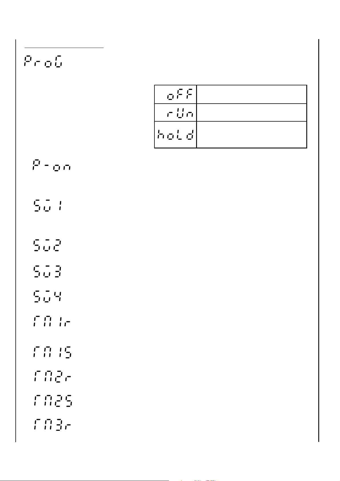
(ramp soak command) Switches the program
(power-on start command) Set this to determine whether
(first-ramp target value) Sets the target value (SV)
operation modes.
Local operation
Program run
Program temporary halt
the power-on start should be
made. (Yes/No)
during each ramp. (0~100%FS
E.U.)
(second-ramp target value)
(third-ramp target value)
(fourth-ramp target value)
(first ramp segment time) Sets the duration (in hours and
minutes) of each time segment
(first soak segment time)
(second ramp segment time)
(second soak segment time)
(third ramp segment time)
61
Page 63

(third soak segment time)
(fourth ramp segment time)
(fourth soak segment time)
(time for rest of the program) The time for rest of the
program is displayed as
follows. This parameter cannot
be set.
When the time for rest is 100 hours or more:
(example: for 100 hours)
When the time for rest is less than 100 hours:
(example: for 99 hours and 59 min)
(present point of program) It displays the program run
status as shown in the
following table. This parameter
cannot be set.
Stop
First ramp running
First soak running
Second ramp running
Second soak running
Third ramp running
Third soak running
Fourth ramp running
Fourth soak running
Program end
62
Page 64

When using the start/reset function, connect an external terminal with
reference to the section “5. Wiring” starting on the page 19. The
operations will be as follows. External contact input takes place at the
time when the contact status (ON/OFF) changes (edge detection).
External contact
(digital input DI)
ON → OFF
OFF → ON
Program stops.
Program runs.
Operation
NOTE:
1. Do not use the auto-tuning function while the ramp soak function is
ON (“
2. The ramp soak command “
supply is switched
” is not ).
” will be set off, once the power
.
63
Page 65

Parameter to be used
Two set-points
* This function is an option.
Two set-points
Changes setpoint with external contact input (Digital Input). See “5.
Wiring” starting on the page 19 for connection of an external contact.
Main Set point
(SV)
Target point
Sub-Set point
( )
Operating procedure
(sub-set point) Set the sub-Set point in parameter
Target value
DI input
sub-Set point value while DI input is
on and, while it is off, the main Set
point value is the target value.
Main
Set point
OFF OFFON
Sub-Set point
DI input
. The target value is the
Main
Set point
64
Page 66

Parameter to be used
Analog output (AO)
* This function is an option.
AO output function
Function to externally output the PV, SV, or MV value with DC1~5V
signals. AO output can be scaled.
Operating procedure
(AO output type) Set the parameter
the desired output signal type.
Measured Value
Setting Value
Manipulated Value
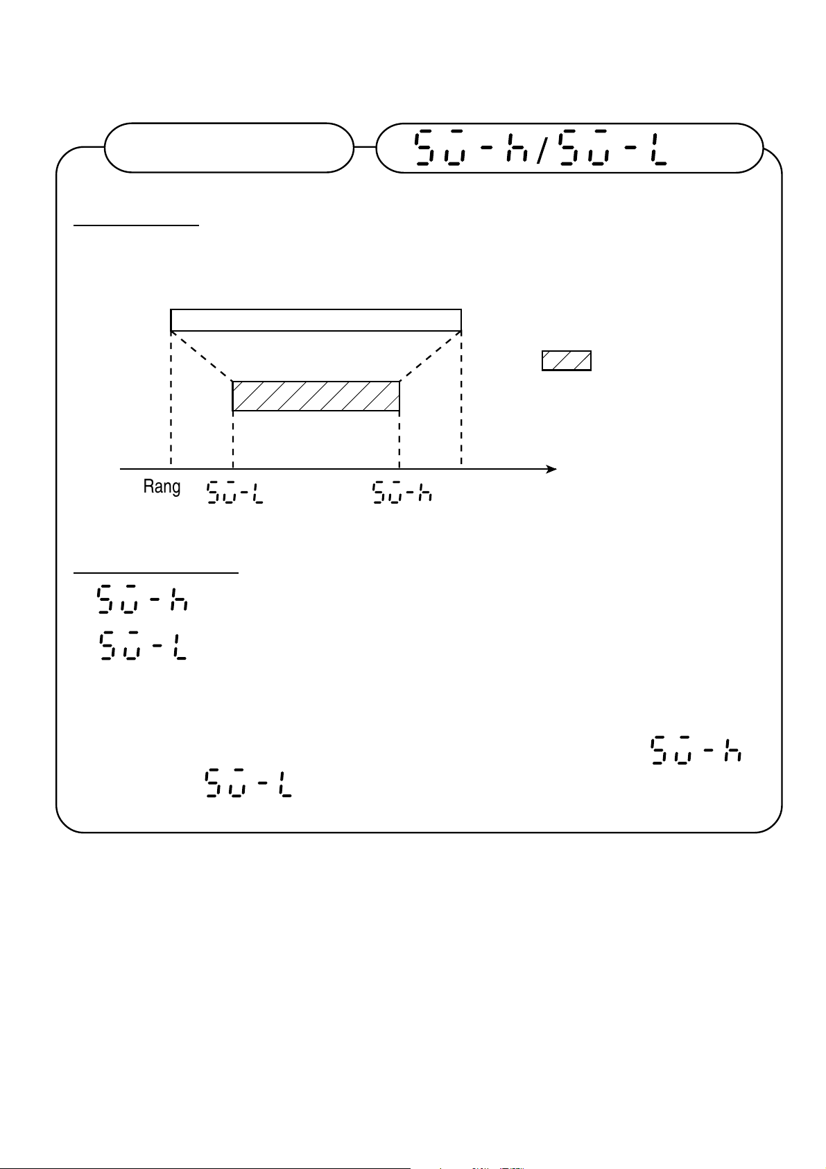
(scale high limit)
(scale low limit) Set the parameters
and to the signal type
values (%) corresponding to the 5V
and 1V output respectively of AO.
(Percentage against the input
range is set when the signal type is
to
PV or SV, the % value with respect
to the input range is set.)
65
Page 67

Example: Input....K thermocouple, 0 ~ 800
°
C range
1~5V signals are to be output when PV values are at 200 -
°
600
Measured
value
800
(°C)
600
(°C)
C.
AO output
5(V)
AO signal type . . . PV value
600°C → 75% of input range
200°C → 25% of input range
(Setting)
200
(°C)
1(V)
0
• • •
• • •
• • •
75.0%
25.0%
NOTE:
1. must be greater than .
66
Page 68

Parameter to be used
Digital output
* This function is an option.
Digital transmission function
Using the RS-485 communication, this function allows remote control
for parameter settings and process monitoring. This employs the multidrop system, and allows connection of a maximum of 31 units. The
communication protocol conforms to the Fuji Electric CC data line
R
protocol or Modbus
RTU (Radio Terminal Unit) protocol. Select
model configuration when you order (See page 6 or 7). For details,
refer to the Fuji Electric PYX Transmission Protocol Specifications
(TN508165-E).
Operating procedure
(station No.) Set the station number (1~31).
Perform transmission in accordance with the PYX Transmission
Protocol Specifications. In case of Fuji Electric CC data line protocol,
the available commands are for polling (parameter read), selecting
(parameter write) and control (parameter save). In case of Modbus
R
RTU (Radio Terminal Unit) protocol, they are for polling (parameter
read) and selecting (parameter write, including parameter save <fix>).
Communication settings are fixed as described below. Make sure that
the host side has the same settings.
Transmission signal ..... RS-485
Transmission rate ........ 9600 bps
Parity ........................... Odd
Stop bit ........................ 1 bit
67
Page 69

NOTES:
1. For the control (parameter save) operation, a maximum of 5 sec is
required for the interval from receiving a command to completing the
operation.
Before ending of that interval, never turn the power
for this device off (otherwise, the memory contents are destroyed
and disabled).
2. This unit requires a time length of 100 to 120mS as the interval from
completing reception of a command from the host before returning
the response. It also requires 20mS before it is able to receive the
next command after completing a reply.
This device
100~120mS
Host Command
Response
20mS
Host Command
Time
Modbus R is a registered trademark of Gould Modicon.
68
Page 70

Manual operation /Set Point value (MV)
Manual mode
Direct manipulation
Operating procedure
(control mode) Switches the control mode
Parameter to be used
Automatic control
Manual control
(During manual mode, the Set point
value and
alternate in
display on the Run screen.)
Set point value Set the manipulated variable to be
output in “%” units into the SP field
of the operation screen. (-3.0-
103.0%)
Supplementary descriptions
1. The normal PID or fuzzy control status is called the auto mode
(
manual mode (
), and manual operation status is referred to as the
).
69
Page 71

NOTE:
1. For the dual control type, the manual control mode is not available.
2. Though the display of manual output can be set in 0.1% unit, the
actual output resolution is 1%.
3. Autotuning cannot be executed in the manual mode.
4. Power supply is off during manual operation, the value of
becomes 0.0%.
5. When the manipulated variable is changed during manual operation,
the proportion cycle being output at that changing point is followed
by the next proportion cycle which starts the actual output of
changed MV.
Present cycle Next cycle
Output changed from
50%~20%
20% output started
70
Page 72

Parameter to be used
Remote SV Set value
* This function is an option.
Remote SV function
This function is used to input a signal of 1 to 5 VDC externally, and
changes and controls the set value (SV) according to the input voltage.
This is useful for cascade control etc.
Operating procedure
Set value
(Select the control mode)
Sets the control mode
The set value (SV) by remote input is displayed
during remote control. (The keys on the front panel
are disabled during remote control.)
(Remote control set value)
The set value (SV) by remote input, regardless of
the current mode. This parameter cannot be
changed.
(Scale high limit)
The remote set values (SV) corresponding
remote input 5V and 1V as the parameter
(Scale low limit)
(0 to 100% FS E.U.)
Enables automatic control.
(See Page 69 for details.)
Enables manual control.
(See Page 69 for details.)
Enables remote control.
to the
and respectively.
Supplementary descriptions
1. See Page 69 for and (automatic and manual modes).
2. When the mode is switched to
(the automatic mode) during
(remote operation), the set value (SV) of the automati c mode will be the same as
the set value of the remote control. (The set value will be switched by bumpless).
3. The set value will be the low limit when the remote input is disrupted.
4. Fuzzy control can be used for set value (SV) changes in steps.
NOTES:
1. must be greater than .
2. Caution is required when executing auto-tuning during remote operation,
since auto-tuning will be disrupted if the set value (SV) changes by more
than 0.5%FS per 0.5 second before the completion of auto-tuning.
71
Page 73

Parameter to be used
Output monitoring
Output monitor function
Numerically displays the MV being output.
Operating procedure
(MV for output1) The currently output value of single-
output or dual-output heating-side
MV is displayed in percent.
(-3.0 to 103.0%)
(MV for output2) The currently output value of dual-
NOTES:
1. Neither
2.
output cooling-side MV is displayed
in percent. (-3.0 to 103.0%)
nor can be set.
is not displayed with the single-output type.
72
Page 74

VI. SET-UP PARAMETER
Parameter to be used
Input filter
Input filter
When a PV value becomes unstable due to effects of noise, the filter
helps suppress the unstable status.
Setting procedure
(input filter constant) Set the filter time constant in sec
units (0.0 ~ 900.0 (sec)).
=0, input filter function is not active.
The filter effects increase as this setting becomes larger, and decrease
as it becomes smaller.
Time constant LargerSmaller
Response SlowerFaster
Effect GreatLittle
73
Page 75

Parameter to be used
PV shift
PV shift
Shifts the PV. Use this function when the PV is to be adjusted
according to a recorder or an indication instrument, or when the sensor
is not in the right position and therefore the PV must be adjusted.
Setting procedure
(PV shift value) Set the shift value to be added to
PV. (-50 ~ 50%FS E.U.)
+
PV Processor
+
74
Page 76

Parameter to be used
Control type
Control type
In addition to PID control, this device is fitted with the fuzzy control
suitable for suppressing overshoot. One of the two can be selected as
the control type.
Setting procedure
(control type) Select the control type.
PID control
Fuzzy control
NOTES:
1. When control is made with the fuzzy, the PID parameter must be set
as with PID control. However, it need not be tuned particularly for
the fuzzy. (The values are allowed to be the same as those for PID
control.)
2. The fuzzy control mode also allows use of the autotuning function.
3. Fuzzy control cannot be used in the dual output type.
4. The two-set-point function is not available in the fuzzy control mode.
5. Fuzzy control can only be used when the set values change in
steps. Attention is required when the ramp soak function or remote
SV function is used.
75
Page 77

Parameter to be used
Output setting in input abnormal
Input abnormal-time output
In the event of an input PV error (e.g. thermocouple burn-out, sensor
disconnection or short-circuit, over-input, under-input etc.), or after the
ramp soak function (option) program ends, the value specified in
advance as the parameter “
value.
Setting procedure
(input abnormal-time output selection code)
Code No. Control output 1
” is out put as the manipulated
Set the code number (0 ~ 4) by
referencing the following table.
Control output 2
0
1
2
3
4
Going on control
-3%
103%
-3%
103%
Going on control
-3%
103%
103%
-3%
Supplement:
1. Set the parameter
to “0” when the control is desired to
be continued after the ramp soak function (option) program
terminates, with the set value prior to the program termination.
NOTES:
1. The parameter “
” specifies only one type of output for
both cases of abnormal input and program end. In other words, the
same operation will be made after an input error and after the
program ends.
76
Page 78

Parameter to be used
Output limits
Output limit
Function to limit the manipulated variable. Used to limit the output
range to favor conditions of the process or operation terminal.
Setting procedure
(MV high limit)
(MV low limit) Set the manipulated-variable high
and low limits (-3.0 ~ 103.0%).
Set point
Set point 3
Set point 2
Set point 1
Set point 4
PV
First ramp First soak
0
TM1R TM1S
Ramp···· Region in which the SP changes toward the target value.
Soak····· Region in which the SP keeps unchanged at the target value.
Second
ramp
TM2R
Second
soak
TM2S
Third
ramp
TM3R
Third soak
TM3S
Fourth
ramp
TM4R
Fourth soak
Time
TM4S
NOTES 1: Setting must always be made to satisfy the condition of
> .
2: Limiting is not valid during manual operation.
3: Auto-tuning provides the 0-100% range output regardless
of limiting.
4: The limiter is not valid for the 2 point (ON/OFF) control.
5: The loop break detection cannot be performed when
“
” exceeds 100.0% or does not reach 0.0%.
77
Page 79
Parameter to be used
Set point vlaue limits
Set point limit
Function to limit the range in which Set point can be set.
Setting allowable range
Range
low limit
Range
high limit
Set point
Setting procedure
(Set point high limit)
(Set point low limit) Set the Set point high and low limits
within the input scale 0 ~ 100%
range. (0 ~ 100%FS E.U.)
NOTES: Setting must be made to satisfy the condition of >
.
78
Page 80

Parameter to be used
Output cycle time
Output proportion cycle time
The relay/SSR drive output delivers the manipulated variable (0 ~
100%) as the proportion of output-off time and output-on time. The
sum of output-on time and output-off time lengths, that is the on/off
cycle time is called the output proportion cycle time.
Output proportion cycle
OFF time ON time
Setting procedure
(Output 1 side proportion cycle time)
(Output 2 side proportion cycle time)
The output proportion cycle time is
set in sec units (1 ~ 120 sec).
Normally the following output
proportion cycle time values must
be specified.
Relay output
SSR drive output
20 seconds
2 seconds
79
Page 81

Supplement:
1. “
current output.
2. “
” and “ ” are not displayed in the case of
” is not displayed in the case of single output type.
80
Page 82

Parameter to be used
Direct/reverse control action
Selecting direct/reverse operation
Selects the direct operation mode (cooling control) or the reverse
operation mode (heating control).
Setting
(operation on the control output 1 side)
Set the operation modes for control
1 and 2 as indicated below.
(operation on the control output 2 side)
NOTE:
1.
Reverse operation (heating control)
Direct operation (cooling control)
is not displayed in the case of single output type.
81
Page 83

Parameter to be used
Control processing cycle time
Control processing cycle time
This function is not supported now.
Please set 0.5 sec. to “dT” parameter.
Cf. Dellivery value of “dT” parameter is 0.5 sec..
82
Page 84

APPENDIX
1. ERROR MESSAGES
Display Cause Control output
1. Thermocouple sensor burn out
2. Thermoresistance sensor disconnection
3. Input exceeding 105% of the input range
1. Thermoresistance sensor disconnection
2. Thermoresistance sensor short-circuit
3. Input under -5% of the input range
1. Heater disconnection
1. Control loop error (cause not specifically
determined)
1. Memory data destroyed Going on control
The value preset in
parameter “ ”
is output. For details,
see "Output setting in
input abnormal" on
page76.
Going on control
If display indicates an error, remove its cause as soon as possible.
2. POWER FAILURE
a) Operation of this device is not affected in case of instantaneous
power failure with a duration of 20ms or less.
b) In case of power failure with a duration of 20ms or more, operation
is made in the same manner as when re-powering on is made.
83
Page 85

3. SPECIFICATIONS
• Input block
Indication accuracy • Thermocouple input
±
0.5%FS±1digit±1 (at 23°C)
°
* B thermocouple 0 ~ 400
C ±5%
R thermocouple 0 ~ 500
• Thermoresistance input
±
0.5%FS±1digit (at 23°C)
• Voltage input, current input (externally
mounted resistance use)
±
0.5%FS±1digit (at 23°C)
Temperature drift •
Reference contact temperature compensation adjustment
Input sampling cycle time • 500msec
Input impedance • Thermocouple: 1M
Allowable signal source resistance
±
0.3%FS/10°C
•
±
1.0°C
• Current input: externally mounted
• Voltage input: 1MΩ or above
• Thermocouple: 250Ω or below
°
C ±1%
Ω
or above
resistance of 250
Ω
• Voltage input: 1k
Allowable wiring resistance • Thermoresistance: 10
(for one wire)
Ω
or below
Ω
or below
84
Page 86

• Output block
Control output • Relay contact output
Proportion cycle time: 20 ~ 120sec
Contact structure: SPST, SPDT
Contact capacity: AC220V/DC30V 3A
(Standard load)
(resistance load)
AC220V/DC30V 1A
(inductive load)
Minimum switching current
Mechanical life: 20 million cycles or more
Electrical life: 100 thousand cycles or
• Voltage pulse output (SSR/SSC drive output)
Proportion cycle time: 1 ~ 120sec
ON voltage: DC9V ~ 24V
OFF voltage: DC0.5V or below
Maximum current: DC20mA
Load resistance: 600
• Current output (DC4 ~ 20mA)
Ensured output range: DC3.52mA ~ 20.48mA
Accuracy:
Linearity:
: 100mA (DC24V)
more (Standard load)
Ω
or above
(-3 ~ 103%)
±
5%FS
±
2%FS
Resolution: 1.0%FS
Follow-up speed: 2 sec or below
Load resistance: 600
• Display block
Display system • 7-segment, 4-digit
• Power supply block
Power supply voltage AC100 ~ 240V, Free power supply
Power supply voltage variation
Power supply frequency 50/60Hz (
Power consumption AC100V: 10VA or below
within -15% ~ +10%
AC240V: 18VA or below
×
2-stage, red, green
±
5%)
Ω
or below
85
Page 87

• External dimensions: (W × H × D) mm:
48
×
48×120.5 (PYX4)
48
×
96×112 (PYX5)
96
×
96×112 (PYX9)
• Weight: Approx. 200g (PYX4)
Approx. 300g (PYX5)
Approx. 400g (PYX9)
• Mounting method: Panel-installed type
• External terminals: screw terminals M3.5
• Ambient temperature -10 ~ 50
• Ambient humidity 90%RH or below (no condensation)
• Warm up 2 hours or above
• Insulation resistance DC500V, 20M
• Control function (PID or fuzzy control selectable)
Basic PID type (Position type)
• Proportional band (P): 0.0 ~ 999.9%, P=0 ON/OFF control
• Integration time (I): 0 ~ 3200 sec, I=0 integration off
• Derivative time (D): 0 ~ 999.9 sec, D=0 derivative off
Fuzzy control
• Digital filter • First-order time-lag filter
• 0.0 ~ 900.0 sec, Set resolution 0.1 sec (0:
OFF)
• PV input compensation • PV shift (
• Over-range, under-range • Outside the range of -5 ~ 105%
°
C
±
Ω
or above
50%FS)
86
Page 88

• Alarm output (ALM1, ALM2 option)
• Output update cycle time: 500msec
• Relay contact output
Contact capacity: AC220V/DC30V 1A
(Standard load) (resistance load)
Minimum switching current: 100mA (DC24V)
Mechanical life: 12 million cycles (200
Electrical life: 100 thousand cycles
• Loop break alarm output (Option)
• Output update cycle time: 500msec
• Alarm setting range: 0.0 ~ 99 min 59 sec
• Relay contact output: Alarm relay also used for
×
2-pts SPST contact
AC220V/DC30V 0.3A
(inductive load)
times/min.)
(Standard load, 20 times/
min.)
• Heater break alarm input signal (option)
1 ~ 30A: CT (CTL-6-SF)
20 ~ 50A: CT (CTL-12-S36-8F) used
*However, the output proportion cycle time must be 20
sec or above.
• Heater break alarm output (option)
• Output update cycle time: 500msec
• Alarm setting range: 1 ~ 50A
• The alarm output relay is also used for this output.
• Ramp/soak function (option)
Program pattern count: 1 pattern
Number of ramps/soaks
per pattern: Maximum of 4
Time indication range: 0 hour 0 min - 799 hours
this
Memory backup: EEP-ROM
OFF/run by digital input possible (only when start/reset
option is provided)
87
Page 89

• Auxiliary analog output (option)
• Number of channels: 1
• Output type: DC1 ~ 5V
Ensured output range: DC0.88V ~ 5.12V (-3 ~
103%)
Accuracy:
Ripple voltage: P-P 1.0%FS or below
Temperature drift:
Load resistance: 500k
• Attached function: scaling function
• Output update cycle time: 500msec
• Digital input (Input by contact)
DC15V~21V 5mA
• Transmission function (option)
RS-485 (2-wire system)
• Transmission system: Half-duplex, bit serial
• Synchronous system: start-stop synchronization
• Coding: data length 8-bit
±
0.5%FS
(50Hz or below)
±
0.3%FS/10°C
Ω
or above
Parity odd
• Transmission rate: 9600BPS
•
Number of units connectible
• Transmission distance: 500m
• Remote SV function (option)
•
Instruction setting accuracy
• Input filter: Digital filter (First-order
• Sampling cycle time: 500msec
• Temperature drift:
• Input impedance: 1M
• Allowable signal: 1K
source resistance
• Attached function: Scaling function
: 31 units
:±0.5%FS±1digit (at 23°C)
time-lag filter) time
constant 1 second
±
0.3%FS/10°C
Ω
or above
Ω
or below
88
Page 90

4. TROUBLESHOOTING
Phenomenon Possible cause User response
Required parameter
not displayed
Set point not changed
Setting of alarm not
displayed
“ ” display
flickering
• Wrong lock level is specified.
• Set point limits not correct
• Ramp/soak command set to other
than (for the type with the
ramp/soak function)
• Alarm type set to "No alarm"
(Code: 0)
• Input error
• Heater break
• Control loop illegally connected
• Set the right lock level. (See Page
44~46.)
• Set the correct Set point limits. (See
Page78.)
• Set the ramp/soak command to
. (See Page 60~63.)
• Set the alarm type to be set. (See
Page 55~59.)
• Check the input or sensor
connection and input switch pin
setting (for multi-input type). (See
Page 19~29, 40.)
• Replace the heater.
• Set the correct control loop.
“ ” display
flickering
“ ” or “ ”
display output
“----” displayed • Input value incapable of being
EEP-ROM data destroyed
• Input error
• Input switch pin illegally set (for
multi-input type)
displayed in four digits
• Replace the main unit.
• Check the input or sensor
connection. (See Page 19~29.)
• Set the input switch pin correctly.
(See Page 40.)
• Make sure the input is appropriate.
89
Page 91

Phenomenon Possible cause User response
Autotuning not
available
" " Set point not
raised (for the type
fitted with heater
break alarming)
• Input error
• Ramp/soak command set to other
than " "
• Manual run being performed
• Set point changed during
autotuning
• Because of the too slow process,
autotuning is not terminated within
12 hours.
• The control output relay has been
switched on not long enough.
• Output proportion cycle time too
short
• Check the input or sensor connection. (See page 19~29.)
• Check the input switch pin correctly.
(See page 40.)
• Set the ramp/soak command to
" " during autotuning. (See
page 60~63.)
• Switch the manual run mode to the
automatic run mode. (See page 69.)
• Do not change the Set point value
during autotuning.
• Autotuning is not available. Perform
manual tuning. (See page 51~54.)
• If the control output relay does not
get triggered at least 1 sec after
powering on, the correct heater
current value cannot be detected.
(See page 58.)
• Set the output proportion cycle time
of " " to 20 sec or more.
(See page 79.)
Loop break detection
not available
Digital transmission
not properly performed
• Output limit setting is illegal • Loop break detection is not
• Host-side setting is wrong.
• Station number is wrong.
• Polarity of transmission
connection is wrong.
available when " " is smaller
than 100.0 or " " is larger
than 0.0. (See page 77.)
• Give the right transmission setting
to the host. (See page 67~68.)
• Set the right station number. (See
page 67~68.)
• Check if the transmission
connection are all right. (See pages
19~29.)
90
Page 92

5. PARAMETER LIST
Lock
Display Name
level
Description
Initial
value
during
shipment
Remarks
LOCK
CAS
OUT1
OUT2
MOD
AT
Lock level
Remote set
0
3
value
Control output 1
output value
3
Control output 2
output value
3
Control
mode
Autotuning
2
1
command
Parameter locking
2
(setting range: 0 ~ 3)
Displays the set value (SV) by
–
remote input.
(Displayed range: 0 to 100% FS E.U.)
Displays the output value of Copntrol
–
Output 1.
(display range: –3.0 ~ 103.0%)
Displays the output value of Copntrol
–
Output 2.
(display range: –3.0 ~ 103.0%)
Setting
Setting
Mode
Auto
Manual
Remote
Autotuning
Stop
Not displayed when
the remote SV
function is disabled.
No setting
No setting
Not displayed
unless control
output 2 is provided.
not
displayed when the
remote SV function
is disabled.
Low-PV type autotuning
D-SV
Sub-Set point
2-setting function sub-set point
2
(setting range: 0 ~ 100%FS E.U.)
STAT
Ramp/soak
present point
Ramp/soak proceeding status is
1
displayed with a symbol. No setting
(display: OFF/1-RP/1-SK/2-RP/2SK/3-RP/3-SK/4-RP/4-SK/END)
TIME
Ramp/soak
remainingoperation
time
The ramp/soak proceeding status is
1
displayed with the time for remaining
operation. When the time for
remaining operation exceeds 100
hours, the hours display of "xxxh" is
made. When the time is under 100
hours, the hour/min display of
"xx.xx" is made. No setting.
* See page 44~46 for lock level.
Normal autotuning
0%FS
E.U.
–
–
Not displayed
unless the 2-setting
function is provided.
Not displayed
unless the
ramp/soak function
is provided.
* E.U.: Engineering Units
* D.E.U. : Deviation engineering Units
91
Page 93

Display Name
PROG
Ramp/soak
command
Lock
level
1
Description
Setting Operation
Function OFF
Run
Temporary stop
Initial
value
during
shipment
Remarks
SV-1
TM1R
TM1S
SV-2
TM2R
TM2S
SV-3
TM3R
First target
value
First ramp
time
First soak
time
Second
target value
Second
ramp time
Second soak
time
Third target
value
Third ramp
time
1
First-ramp target value (setting
range:0~100%FS E.U.)
1
First-ramp segment time (hour/min)
(setting range:00.00~99.59)
1
First-soak segment time (hour/min)
(setting range:00.00~99.59)
1
Second-ramp target value (setting
range:0~100%FS E.U.)
1
Second-ramp segment time
(hour/min) (setting range:00.00~99.59)
1
Second-soak segment time (hour/min)
(setting range:00.00~99.59)
1
Third-ramp target value (setting
range:0~100%FS E.U.)
1
Third-ramp segment time (hour/min)
(setting range:00.00~99.59)
0%FS
E.U.
00.00
00.00
0%FS
E.U.
00.00
00.00
0%FS
E.U.
00.00
Not displayed
unless the
ramp/soak function
is provided.
TM3S
SV-4
TM4R
TM4S
P-ON
P
Third soak
time
Fourth target
value
Fourth ramp
time
Fourth soak
time
Power-on
start
Proportional
band
1
Third soak segment time (hour/min)
(setting range:00.00~99.59)
1
Fourth-ramp target value (setting
range:0~100%FS E.U.)
1
Fourth-ramp segment time (hour/min)
(setting range:00.00~99.59)
1
Fourth-soak segment time (hour/min)
(setting range:00.00~99.59)
2
Ramp/soak power-on start
command (setting range:NO/YES)
2
setting range:0.0~999.9%
92
00.00
0%FS
E.U.
00.00
00.00
NO
5.0
'0' for ON-OFF
control
Page 94

Display Name
Lock
level
Description
Initial
value
during
shipment
Remarks
HYS
I
D
COOL
DB
AR
MAN
2-point
operation
hysteresis
Integration
time
Derivative
time
Control output 2
proportional
band
coefficient
Dead band
Antiresetting
wind up
Manual
resetting
value
2
(setting range:0~100%FS D.E.U.)
2
(setting range:0~3200sec)
2
(setting range:0.0~999.9sec)
2
Control output 2 proportional band
coefficiency. ‘0’ for 2-point operation
(setting range: 0.0~10.0)
3
Control output 2 shift value
(setting range:–50~50%)
3
The integration range is set
(setting range: 0.0~100.0% D.E.U.)
3
MV shift
(setting range:–100.0~100.0%)
0.5%FS
D.E.U.
240
60.0
1.0
0.0
100
%
FS
(D.E.U.)
0.0
Not displayed
except when P = 0.
At '0', integration
operation turns off.
At 0, derivative
operation turns off.
Not displayed
unless control
output 2 is
provided.
AL1T
AL11
A11H
Types of
alarm-1
Alarm 1-1
Set point
Alarm 1-1
hysteresis
2
Dedicated to loop/heater
disconnection
2
Set point of Alarm 1-1
(setting range: 0~100%FS E.U.)
3
Hysteresis for alarm 1-1
(setting range: 0~100%FS D.E.U.)
1-3
type
1-2
type
1-1
type
Not displayed
0003
1000 for
the HB
10 °C/°F.
(0%FS
E.U. for the
HB-fitted)
0.5%FS
(D.E.U.)
unless alarm 1
is provided.
fitted
Not displayed
when alarm 1 is
not provided,
and when
setting is not
made for alarm
1-1.
93
Page 95

Display Name
Lock
level
Description
Initial
value
during
shipment
Remarks
AL12
A12H
AL13
AL13H
AL2T
Alarm 1-2
Set point
Alarm 1-2
hysteresis
Alarm 1-3
Set point
Alarm 1-3
hysteresis
Type of alarm
2
Alarm 1-2 Set point
2
(setting range: 0~100%FS E.U.)
Alarm 1-2 hysteresis
3
(setting range: 0~100%FS D.E.U.)
Alarm 1-3 Set point
2
(setting range: 0~100%FS E.U.)
Alarm 1-3 hysteresis
3
(setting range: 0~100% FS D.E.U.)
2
Dedicated to loop/heater
disconnection
2-3
type
2-2
type
2-1
type
0%FS
0.5%FS
(D.E.U.)
0%FS
0.5%FS
(D.E.U.)
0004
1000 for the
HB-fitted
E.U.
E.U.
Not displayed
when alarm 1
is not
provided, or
when setting
is not made
for alarm 1-2.
Not displayed
when alarm 1
is not
provided, or
when setting
is not made
for alarm 1-3.
Not displayed
unless alarm 2
is provided.
AL21
A21H
AL22
A22H
Alarm 2-1
Set point
Alarm 2-1
hysteresis
Alarm 2-2
Set point
Alarm 2-2
hysteresis
Set point of alarm 2-1
2
(setting range: 0~100%FS E.U.)
Hysteresis for alarm 2-1
3
(setting range: 0~100%FS D.E.U.)
Alarm 2-2 Set point
2
(setting range: 0~100%FS E.U.)
Alarm 2-2 hysteresis
3
(setting range: 0~100%FS D.E.U.)
10 °C/°F.
(0%FS
E.U. for the
HB-fitted)
0.5%FS
(D.E.U.)
0%FS
0.5%FS
(D.E.U.)
E.U.
Not displayed
when alarm 2
is not
provided, and
when setting
is not made
for alarm 2-1
and alarm 2.
Not displayed
when alarm 2
is not
provided, or
when setting
is not made
for alarm 2-2.
94
Page 96

Display Name
Lock
level
Description
Initial
value
during
shipment
Remarks
AL23
AL23H
Loop
HB-A
CT
PVT
Alarm 2-3
Set point
Alarm 2-3
hysteresis
Loop break
alarm
Set
point
Heater break
alarm
Set point
Heater current
PV type
Alarm 2-3 Set point
2
(setting range: 0~100FS E.U.)
Alarm 2-3 hysteresis
3
(setting range: 0~100FS D.E.U.)
Loop break alarm detection time
2
(min/sec) (setting range: 00.00~99.59)
Heater break alarm detection current
2
(setting range: 1~50A)
Heater current monitor
2
No setting (display range: 0~50A)
Input type, presence or absence of
3
decimal point, and°C/°F specified
Input
type
Presence or absence
of decimal point
°C/°F
0%FS
E.U.
Not displayed
when alarm 2
is not provided,
0.5%FS
(D.E.U.)
00.00
50A
–
or when setting
is not made for
alarm 2-3.
Not displayed
unless
alarming is
provided.
Not displayed
unless heater
break alarming
is provided.
2200
unless
otherwise
specified
(K
thermo-
couple, 0
- 400 °C)
PVF
PVB
PVD
TF
Full scale
Base scale
Scaling
decimal-point
location
Input filter
Scaling full scale
3
(setting range:–1999~9999)
Scaling base scale
3
(setting range:–1999~9999)
Scaling decimal-point location
3
"2" "1" "0":none
Input filter time constant
3
Setting 0.0 turns the filter off.
(setting range: 0.0~900.0sec)
95
1000
0
1
5.0
Displayed only in the
voltage or current
input mode.
Page 97

Display Name
SFT
PV shift
Lock
level
PV shift value
3
(setting range:–50~50%FS D.E.U.)
Description
Initial
value
during
shipment
0%FS
(D.
E.U.)
Remarks
SV-H
SV-L
REMF
REMB
CTRL
DT
REV1
Set point high
limit
Set point low
limit
Remote
scaling full
scale
Remote
scaling base
scale
Control operation
system
Control operation
cycle time
Control output 1
direct/reverse
operation selection
Set point high limit
3
(setting range:0~100%FS E.U.)
Set point low limit
3
(setting range:0~100%FS E.U.)
The full scale for remote input scaling
3
(Set range: 0 to 100% FS E.U.)
The base scale for remote input scaling
3
(Set range: 0 to 100% FS E.U.)
Control operation algorithm selected
2
(setting range: PID/FUZY)
3
(Setting range: REV/NORM)
3
100%FS
0%FS
E.U.
100% FS
industrial
value
0% FS
industrial
value
PID
0.5 sec
Not displayed
when the
remote SV
function is
disabled
REV2
TC-1
TC-2
Control output 2
direct/reverse
operation selection
Control output 1
output proportion
cycle time
Control output 2
output proportion
cycle time
(Setting range: REV/NORM)
3
(Setting range: 1~120 sec)
3
(Setting range: 1~120 sec)
3
Relay
output: 20
sec, SSR
drive: 2 sec
Relay
output: 20
sec, SSR
drive: 2 sec
Not displayed
when control
output 2 is not
provided.
Not displayed
when output 1
is 4 - 20mA.
Not displayed
when 4 - 20mA
output or
without control
output 2.
96
Page 98

Display Name
Lock
level
Description
Initial
value
during
shipment
Remarks
MV-H
MV-L
BURN
A0T
A0-H
MV high limit
MV low limit
Output setting in
input abnormal
AO output type
AO scaling full
scale
(setting range: –3.0~103.0%)
3
(setting range: –3.0~103.0%)
3
3
3
3
Setting Output 1
Going on control
–3.0%
103.0%
–3.0%
103.0%
Setting AO source
AO output scaling full scale
(setting range: 0.0~100.0%)
Output 2
Going on control
–3.0%
103.0%
103.0%
–3.0%
PV
SV
MV
100.0
0.0
1
Not displayed
unless AO is
provided
100.0
A0-L
STNO
AO scaling base
scale
Station No.
AO output scaling base scale
3
(setting range: 0.0~100.0%)
Transmission originating station number
2
(setting range: 1~31)
0.0
1
Not displayed
unless
transmission
is provided.
97
 Loading...