

Page 1

Instruction Manual
MICRO CONTROLLER H
Z SERIES
TYPE: PYH
INP-TN3PYHd-E
Page 2

PREFACE
Congratulations on your purchase of Fuji Digital Temperature Controller (Type: PYH)
•Read this instruction manual carefully to ensure correct installation, operation and preparation.
Incorrect handling may lead to accidnt or injury.
• Specifications of this unit is subject to change without prior notice for improvement.
•Modification of this unit without permission is strictly prohibited.
Fuji will not bear any responsibility for a trouble caused by such a modification.
• This instruction manual should be kept by the person who is actually using the unit.
• After reading the manual, be sure to keep it at a place easy to access.
• This instruction manual should be delivered to the end user without fail.
Manufacturer : Fuji Electric Co., Ltd.
Type : Shown on nameplate of main frame
Date of manufacture : Shown on nameplate of main frame
Product nationality : Japan
The product conforms to the requirements of the Electromagnetic compatibility Directive 89/336/EEC
as detailed within the technical construction file number TN510403. The applicable standards used to
demonstrate compliance are:
EN 50081-1 : 1992 Conducted and Radiated emissions
EN 50082-1 : 1992 Radiated immunity, ESD and FBT
(The unit meets Class A limits for conducted Emissions.)
The unit also complies with the part of Immunity standards.
IEC 1000-4-2 : 1995 level 3, IEC 1000-4-3 : 1995 level 3
IEC 1000-4-4 : 1995 level 3, IEC 1000-4-8 : 1993 level 4
© Fuji Electric Co., Ltd. 1993
Request
•Transcription of a part or the whole of this manual without permission is
prohibited.
•The contents of this manual are subject to change without prior notice.
Issued in November, 1993
Rev. 1st edition November, 1993
Rev. 2nd edition February, 1996
Rev. 3rd edition April, 1997
Rev. 4th edition February, 2002
INP-TN3PYH-E i
Page 3
CAUTION ON SAFETY
First of all, read this “Caution on Safety” carefully, and then use the instrument in the correct way.
The cautionary descriptions listed here contain important information about safety, so they should always be observed.
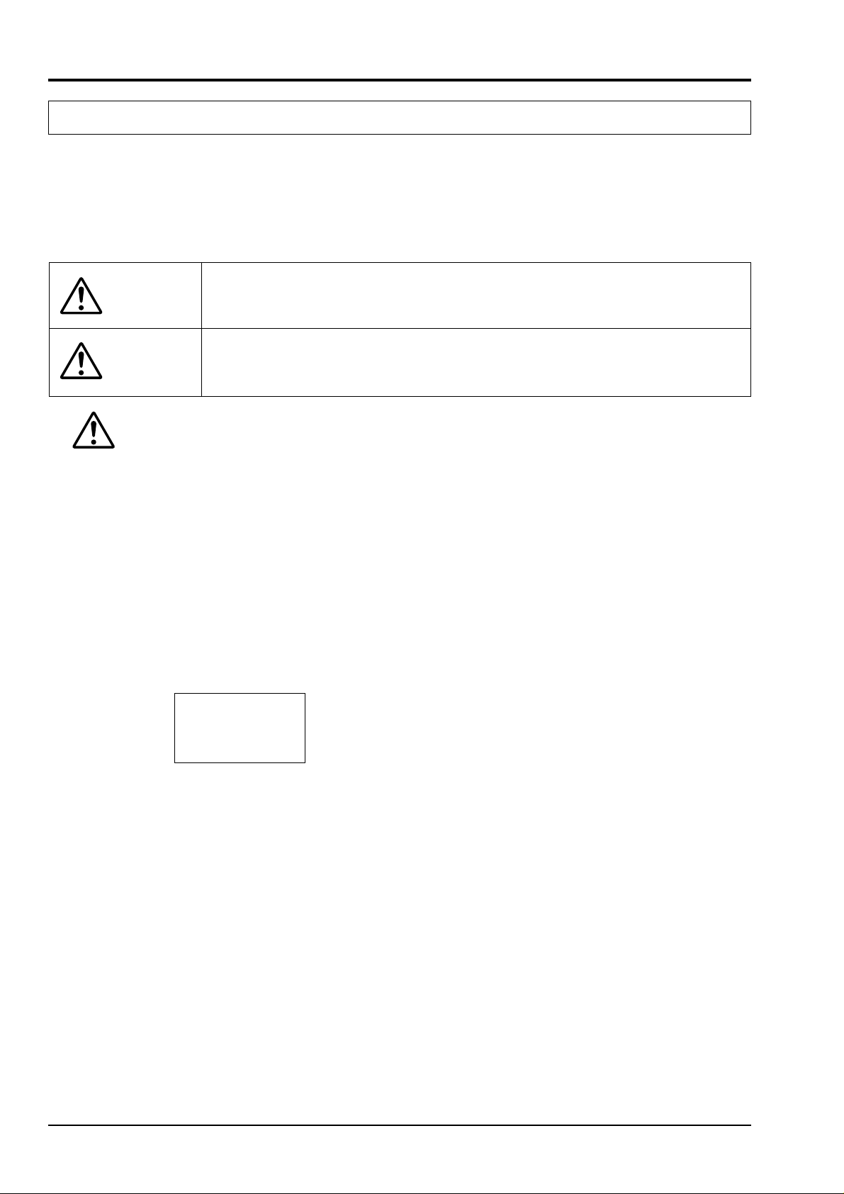
Those safety precautions are classified in 2 ranks, WARNING and CAUTION.
The following shows the meaning of WARNING and CAUTION.
Wrong handling may cause a dangerous situation, in which there is a possibility of death or
WARNING
CAUTION
1. WARNING
heavy injury.
Wrong handling may cause a dangerous situation, in which there is a possibility of injury or
physical damage.
1.1 Caution on wiring
(1) For the safe operation of the controller, where the temperature probe is to be installed into an environment where
voltage exceed 50V DC, it is essential that reinforced isolation or basic isolation and earth is maintained between
all connections to the rear of the temperature controller, and that supplementary isolation is required for the alarm
outputs.
The outputs from the controller are all less than 50V DC.
When wiring the power supply terminal, use vinyl insulated 600 volt cable or equivalent. A switch breaking both
poles of the mains supply should be installed together with a fuse with a rating of 250 volt 1 Amp. The fuse
should be installed between the mains switch and the controller.
The level of insulation provided by the temperature controller is:-
MAINS = BASIC
HEATER = BASIC
INPUTS = –––
Prior to operation of the installed system the wiring should be checked to ensure that the required levels of insulation have been provided.
(2) When a fault in the instrument is likely to lead to a serious trouble, use a suitable protective circuit on the outside
for protection against trouble.
(3) This unit is not provided with power switch, fuse, etc. These parts can be installed separately, if required (fuse
rating; 250V, 1A).
(4) Use of Fuji’s Z-Trap is recommended to protect the relay output from switching surge and to ensure a long life.
Type: ENC241D - 05A (power voltage; 100V)
ENC471D - 05A (power voltage; 200V)
Mounting position: Connected to relay control output terminals
ii INP-TN3PYH-E
Page 4

CAUTION ON SAFETY
1.2 Power source
(1) Use a power source of rated voltage to prevent damage or trouble.
(2) Do not turn ON the power until the wiring is completed to prevent shock hazard or trouble.
1.3 Prohibition of use in gas
The instrument is not an intrinsic safety explosion-proof type. Do not use it in a place exposed to combustible or
explosive gas.
1.4 Contact to unit
(1) This unit must not be disassembled, modified or repaired to prevent malfunction, shock hazard or fire accident.
(2) When the power is ON, do not touch the terminals to prevent shock hazard or malfunction.
1.5 Caution on maintenance
(1) Before mounting or removing the module or unit, turn OFF the power in advance to prevent shock hazard, mal-
function or trouble.
(2) Periodical maintenance is recommended to ensure continuous and safe operation of the instrument. Some parts of
the instrument are limited in life or are subject to secular change.
2. CAUTION
2.1 Caution on handling
(1) Do not install the unit in any of the following places.
•A place where the ambient temperature exceeds the range of -10 to 50°C
•A place where the ambient humidity exceeds the range of 45 to 85%RH
•A place where temperature changes suddenly or dew condensation occurs
•A place exposed to corrosive gases (sulfuric gas, ammonia, etc.) or combustible gases
•A place where vibration or shock is likely to be directly transmitted to the body
•A place exposed to water, oil, chemicals, vapor, steam, etc.
•A place with much dust, salt or iron component
•A place with much inductive disturbance, static electricity, magnetism or noise
•A place exposed to direct sunlight
•A place where heat such as radiant heat stays
(2) Mounting
For mounting, attach the supplied mounting brackets (2 units) on top and bottom and tighten with a screwdriver.
Tightening torque is about 147N·cm. (The case is made of plastic. Care should be taken not to tighten forcedly.)
(3) When the unit is exposed to water, it may lead to a short-circuit or fire hazard. Contact your dealer for inspection.
2.2 Caution on cable connection
(1) For thermocouple input, use a suitable compensating cable.
(2) For resistance bulb input, use a cable with a small lead wire resistance and without resistance difference between 3
wires.
(3) When external wiring has much noise, use the following step. When a conducted as load of digital output such as
relay contact output or alarm output, connect a surge absorber to the conductor coil. (Example: ENC471D-05A
for 200V AC)
INP-TN3PYH-E iii
Page 5

CAUTION ON SAFETY
(4) When the power source has much noise, use an insulating transformer together with a noise filter. Noise filter
should be mounted on a panel which has been earthed. The wiring between the noise filter output and the instrument power terminals should be as short as possible. Do not connect a fuse or switch to the noise filter output
wiring, as it affects the performance of the filter.
(5) Use of a twisted cable for the instrument power source provides better effects (short twist pitch is effective for
noise).
(6) When a heater burnout alarm is provided, the heater power and controller power should be connected using the
same power line.
(7) Time for preparation of contact output is required at power ON. When the output signal is used for an external
interlock circuit, etc., connect a delay relay to the circuit.
2.3 Other
When cleaning the instrument, do not use organic solvents such as alcohol, benzine, etc. Use neutral detergent.
3. Caution on key operation/trouble
(1) Alarm function should be set correctly. Otherwise, alarm output cannot be obtained at the time of occurrence of
trouble. Be sure to check the function prior to operation.
(2) Do not stop the device forcedly during auto-tuning, as it affects the control action. When it needs to stop forcedly,
be sure to turn OFF the power in advance.
(3) If the input cable is disconnected, the display shows UUUU or LLLL. When replacing the sensor, be sure to turn
OFF the power.
iv INP-TN3PYH-E
Page 6

CONTENTS
PREFACE .....................................................................................................................i
CAUTION ON SAFETY............................................................................................ ii
1. RATINGS.............................................................................................................1
2. PERFORMANCE.................................................................................................3
3. OPERATING PARTS AND THEIR FUNCTIONS ............................................4
4. PREPARATION FOR OPERATION, AND OPERATION................................6
4.1 Preparation for operation....................................................................................... 6
4.2 Operation ............................................................................................................... 6
4.3 Selection of operation mode................................................................................ 10
5. FAULT INDICATION.......................................................................................13
6. USE OF HEATER ALARM (OPTION)............................................................15
7. CHANGING OF FUNCTIONS .........................................................................17
7.1 Method of changing specifications...................................................................... 17
8. DUAL OUTPUT CONTROL TYPE .................................................................22
9. SV SELECTION ................................................................................................24
10. POSITION FEEDBACK CONTROL TYPE.....................................................25
11. INVERTER CONTROL TYPE..........................................................................26
12. PARAMETER SET VALUE TABLE ................................................................27
13. OUTLINE DIMENSIONS AND PANEL CUTOUT ........................................33
14. CONNECTION DIAGRAM..............................................................................34
15. PARAMETER LIST ..........................................................................................35
16. INSTALLATION AND WIRING......................................................................37
17. CODE SYMBOLS .............................................................................................39
INP-TN3PYH-E v
Page 7
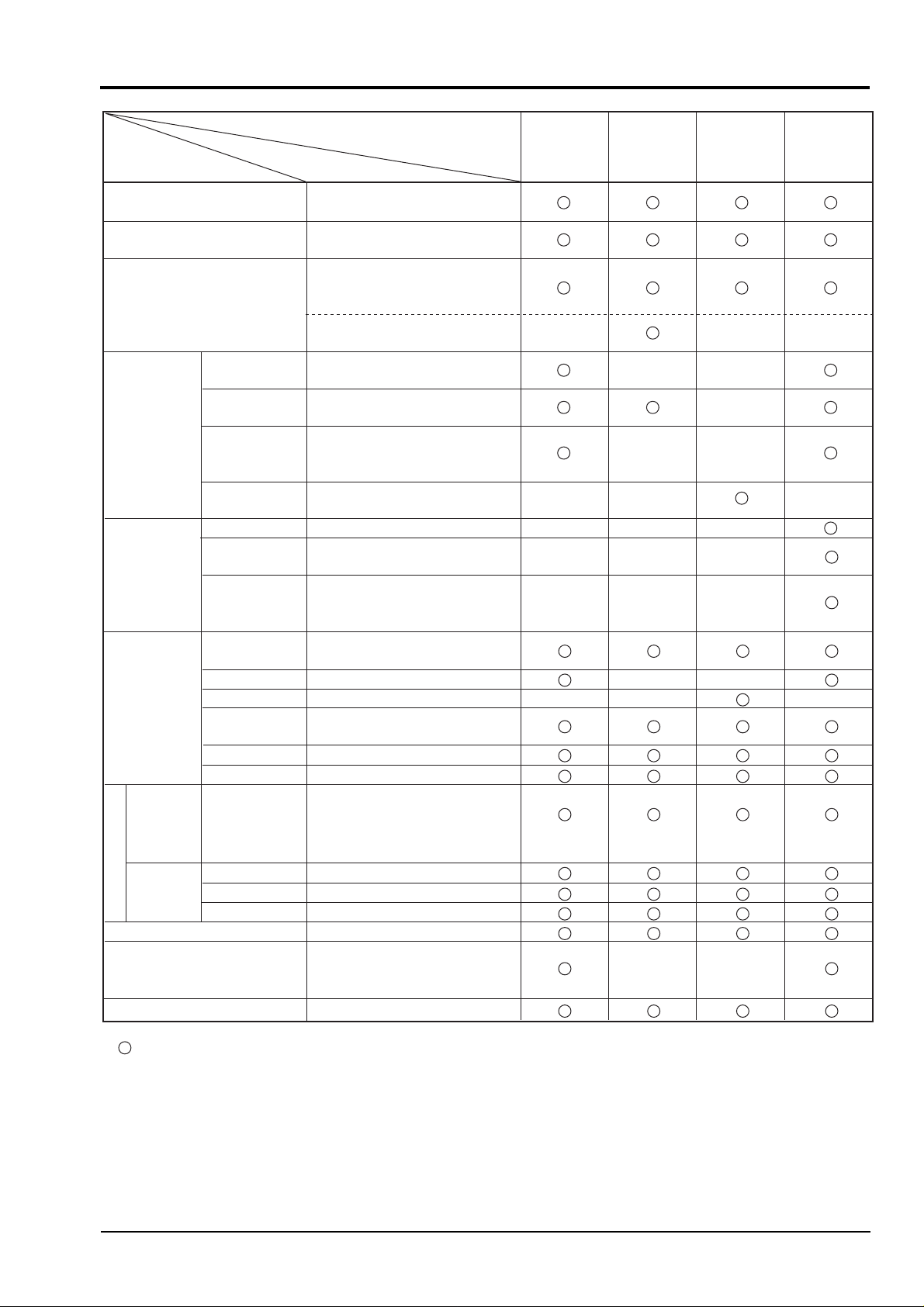
1. RATINGS
Item
Power source voltage
Power consumption
Input
(measured value)
Relay contact
Current
Control
output 1
Control
output 2
(dual control
type only)
Auxiliary
input
PV/SV/MV
transmission
output
Auxiliary
alarm
Auxiliary output
output
Main alarm output
Heater burnout alarm output
Fault output
SSR/SSC drive
Motor-driven
valve operation
Relay contact
Current
SSR/SSC drive
Analog
Heater current
Opening
Digital 1
Digital 2
Digital 3
Analog *3
Digital 1
Digital 2
Digital 3
Type
Rating
85 to 264V AC, 50/60 Hz,
free power source
About 20 VA (100V AC)/
About 30 VA (220V AC)
Thermocouple, resistance bulb,
voltage, current,
mV input (leak current=3µA typ.)
With transmitter power 4 to
20 mA DC. (PYH9 only)
220V AC, 3A, 1c contact
(resistive load)
4 to 20mA DC, load resistance,
600Ω or less
10V to 27V DC at ON, 0.5V DC
or less at OFF, max. current,
20mA DC.
220V AC, 3A, la contact × 2
220V AC, 3A, 1c contact
4 to 20mA DC, load resistance,
600Ω or less
10V to 27V DC at ON,
0.5V DC or less at OFF,
max. current, 20mA DC.
1 to 5V DC, input resistance,
1MΩ or more *1
1 to 50A AC.
100 to 1000Ω, 3-wire system
Contact, OFF at 24V DC,
Ditto (PYH9 only)
Ditto (PYH9 only) *2
1 to 5V DC, input impedance of
connected device, 500kΩ or
more
30V DC, 0.1A, la contact *4
Ditto
Ditto (PYH9 only)
220V AC, 1A, la contact × 2
220V AC, 1A, la contact
(PYH5: Open-collector
30V DC, 0.1A, 1b contact
ON at 0V DC (15 mA)
(30V DC, 0.1A))
Fixed set
point control
type
−−
−
−
−
−
−
Inverter
control type
(PYH9 only)
−
−
−−
−
−
−−
−
Position
feedback
control type
−
−
−
−
−−
−−
−
−
Dual
control type
−
: Applicable : Not applicable
*1: If “A” or “C” is not specified in the 11th digit of PILC, do not use the instrument because it will not operate normally.
*2: Auxiliary digital input 3 can be used when it is the T-Link transmission specifications or on SV selection.
*3: If “B” or “C” is not specified in the 11th digit of PILC, do not use the instrument because it will not operate normally.
*4: Open collector in case of PYH5
INP-TN3PYH-E 1
−
Page 8
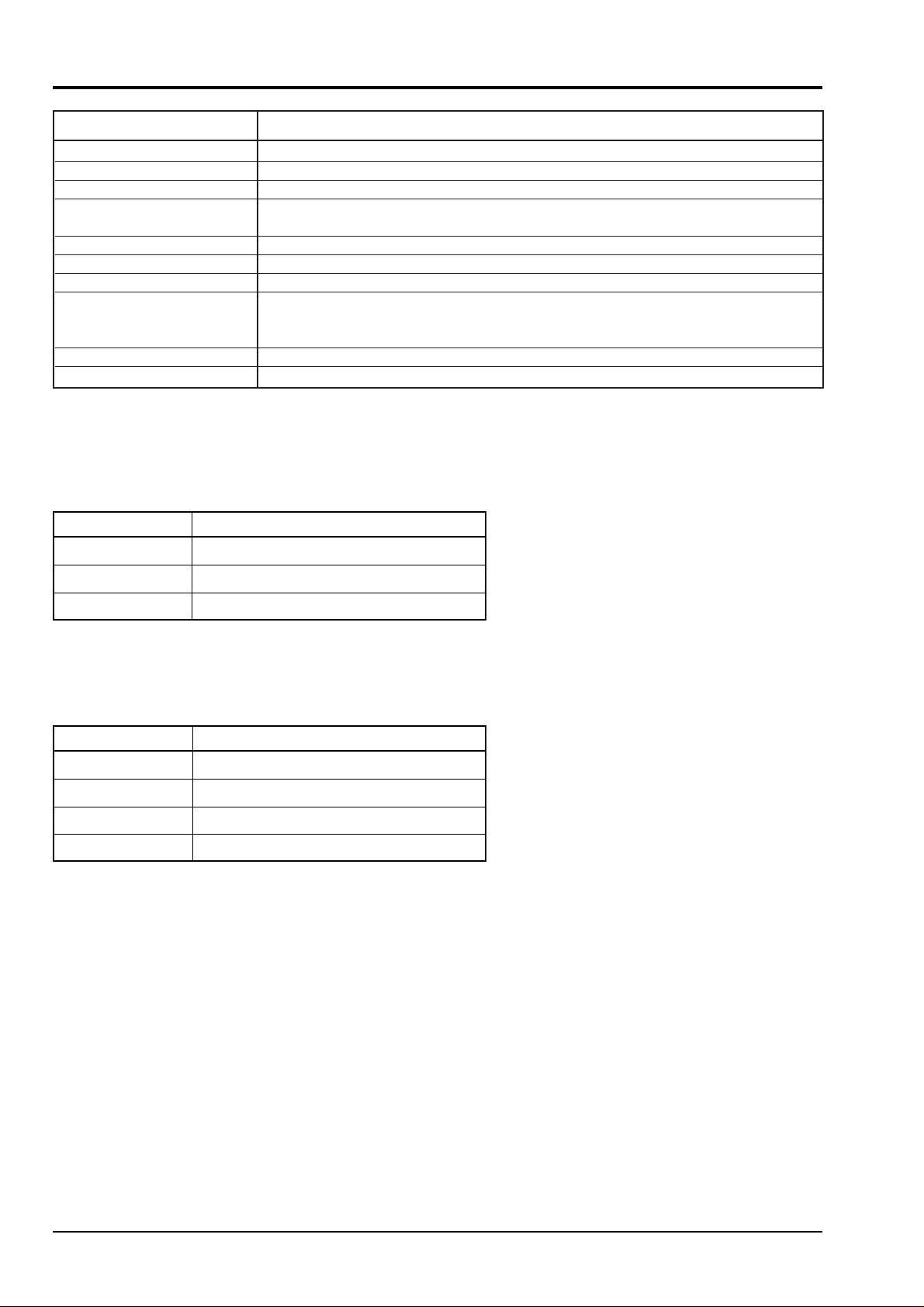
1. RATINGS
Item Rating
Setting method
Indicating method
Transmission function
Operating ambient
temperature
Operating ambient humidity
Storage temperature
Enclosure case
External dimensions
(unit: mm)
Mass
Finish color
Wiring resistance of allowable input signal
Input signal Allowable input signal wiring resistance
Thermocouple, mV 50Ω or less per wire
Resistance bulb 10Ω or less per wire
Key switch (data continuous change method)
7 segments, LED 4 digits × 2, mode indication
RS-485, T-link (PYH9 only) *5
-
10 to +50°C
90% RH or less (no condensation)
-
10 to +70°C
Plastic housing
PYH5: 96(H) × 48(W) × 150(D)
PHY7: 72(H) × 72(W) × 150(D)
PHY9: 96(H) × 96(W) × 150(D)
PYH5/PYH7, approx. 0.5kg, PYH9, approx. 0.8kg
Munsel N1.5 (black)
*5: T-Link is a name of Fuji Electric informa-
tion network.
*6: Built in the instrument (external resistor is
not required.)
1 to 5V DC 10Ω or less
Input impedance
Input signal Input impedance
Thermocouple 1MΩ
Resistance bulb ––
1 to 5V DC 1MΩ
4 to 20mA DC 250Ω *6
2 INP-TN3PYH-E
Page 9

2. PERFORMANCE
Setting accuracy ±0.2% FS±1 digit
Indication accuracy ±0.2% FS±1 digit, temperature compensation ±1°C
Note) Refer to Table 1 (P.18).
Remote setting input accuracy ±0.2% FS
Proportional band (P) 0 to 3276% (with dead band ON-OFF operation at P = 0)
Integrating time (I) 0 to 3276 s
Derivative time (D) 0 to 900 s
Main alarm setting range Within full scale
Sampling cycle 100 ms
Control cycle 0.1 to 3276 s
Time proportion cycle 1 to 255 s
Insulation resistance 20MΩ or more (at 500V DC)
Withstand voltage 1500V AC for 1min. Between power supply and relay contact output, power
supply and the earth, and the earth and relay contact output
500V AC for 1 min. others
Output relay life
Mechanical 107 operations (100 ON-OFF operations/min.)
Electrical 105 operations (20 ON-OFF operations/min. at rated load)
Protective structure Front panel, IEC standards, IP55 (dust-drip proofing)
Terminal unit, IEC standards, IP00
Current output accuracy ±2% FS
INP-TN3PYH-E 3
Page 10
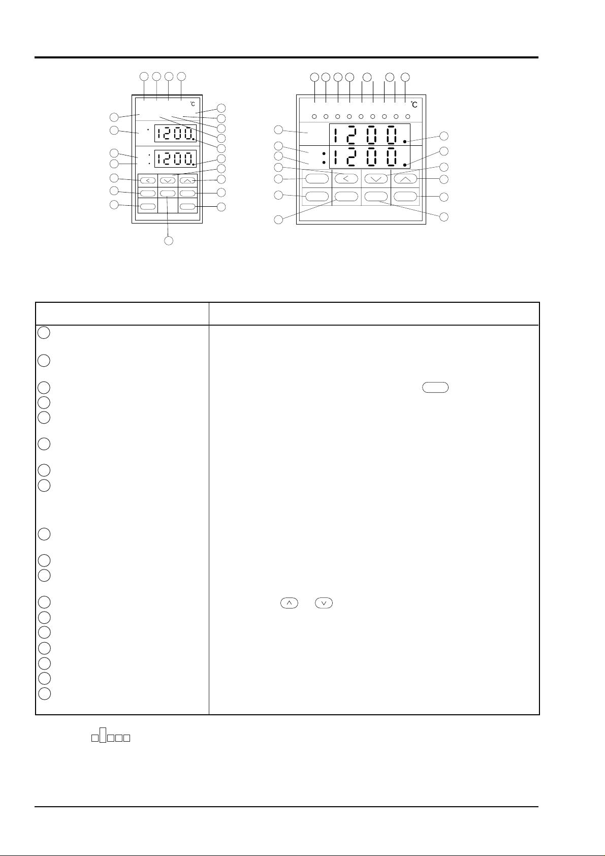
3. OPERATING PARTS AND THEIR FUNCTIONS
4 5 6 7
FLT R A M
C1 C2 H L HB
8
1
PV
2
SV
MV
3
12
11
15
SEL
SV/MV
A/M ENT
16
PYH5
Item
1
Measured value (PV) indication (red)
2
Set value (SV) indication (green)
Control output (MV) indication
3
Instrument fault lamp (red)
4
5
Remote operation lamp (green)
6
Auto operation lamp (green)
7
Manual operation lamp (green)
8
Control output lamp (green)
9
Alarm lamp (red)
10
Heater burnout alarm lamp (red)
11
SV-MV select key
12
Fast key
13
Down key
14
Up key
Auto/manual select key
15
Select key
16
17
Data key
18
Entry key
DATA
10
987654
C1
10
9
9
8
19
20
13
14
17
18
1
2
3
12
11
15
16
FLT HB
PV
SV
MV
SV/MV
A/M
MA
R
C2
SEL DATA ENT
LH
19
20
13
14
18
17
PYH 7, 9
Function
Measured value (PV) is indicated during operation.
Abbreviation of parameter is indicated when setting parameter.
Set value (SV) is indicated during operation.
Data of parameter is indicated when setting parameter.
Control output (MV) is indicated by selecting with key.
SV/MV
This lamp lights at instrument failure.
This lamp lights when operating with input of external set value
(lamp is ON during remote operation).
This lamp lights when operating with SV value set by the front key
(lamp ON during auto operation).
This lamp lights during manual operation.
C1: This lamp lights when control output 1 is given.
(not light when current output is given) *1
C2: This lamp lights when control output 2 is given.
(not light when current output is given) *1
H: This lamp lights when higher limit main alarm is output.
L: This lamp lights when lower limit main alarm is output.
This lamp lights when heater burnout alarm is output.
This key is used for selection between SV and MV indications.
By pressing the key after setting parameter, operation mode is indicated.
By pressing the or key, the data change is sent in fast-forward mode.
This key is used to decrease the value of data to be set.
This key is used to increase the value of data to be set.
This key is used for selection between auto and manual operation.
This key is used to call parameters.
This key is used to change the data of parameters.
This key is used to register the data in PYH after changing the data of
parameters.
*1: PYH lamp is set at OFF before shipment. When the ConF Ch <output terminal definition channel>
D
E
is set with Do1=0F (motor value is open) and Do2=0E (motor valve is closed), the lamp is turned ON/OFF
linked with output ON/OFF.
4 INP-TN3PYH-E
Page 11

3. OPERATING PARTS AND THEIR FUNCTIONS
Indication
Contents
This lamp lights during auto-tuning.
This lamp lights during host transmission operation.
PV
SV
• When parameter is indicated or it is left as it is after setting, operation indication is indicated automatically about
13 minutes later.
19
20
INP-TN3PYH-E 5
Page 12
4. PREPARATION FOR OPERATION, AND OPERATION
4.1 Preparation for operation
To ensure correct operation of the controller, it is necessary to set parameters before operating, according to the
procedures shown in (3) Setting method of main alarm set values (AL1, AL2) of item "4.2 Operation". While
setting parameters, be sure to stop the operation of the external system for the sake of safety.
Kinds of parameters
Refer to "15. Parameter list" on page 35. Note that some parameters in "15. Parameter list" are not used depending
on the type of PYH, which are not displayed by the indicator on the front of PYH.
4.2 Operation
(1) When power turns ON, measured value (PV) and set value (SV) are indicated a few seconds later to start operating.
The indication of measured value and set value is called the operation indication.
Heat up time of PYH is two hours. Measuring and controlling of PYH should be operated after the heat up time.
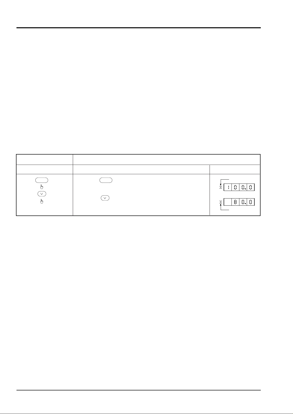
(2) Setting of set value (SV)
Contents of operation
Key operation
SV/MV SV/MV
(Note) If the power for PYH is turned OFF within 10 seconds after changing the set value, it can result in
misoperation. Be sure to turn OFF the power more than 10 seconds after the set value has been changed.
Change of set value from 100.0°C to 80.0°C
Description Indication
• Press the key to light the SV lamp.
(SV lamp should be kept lighting.)
• Using the key, set the set value (SV) to 80.0.
- Operation completed -
SV lamp
SV
SV
SV lamp
6 INP-TN3PYH-E
Page 13
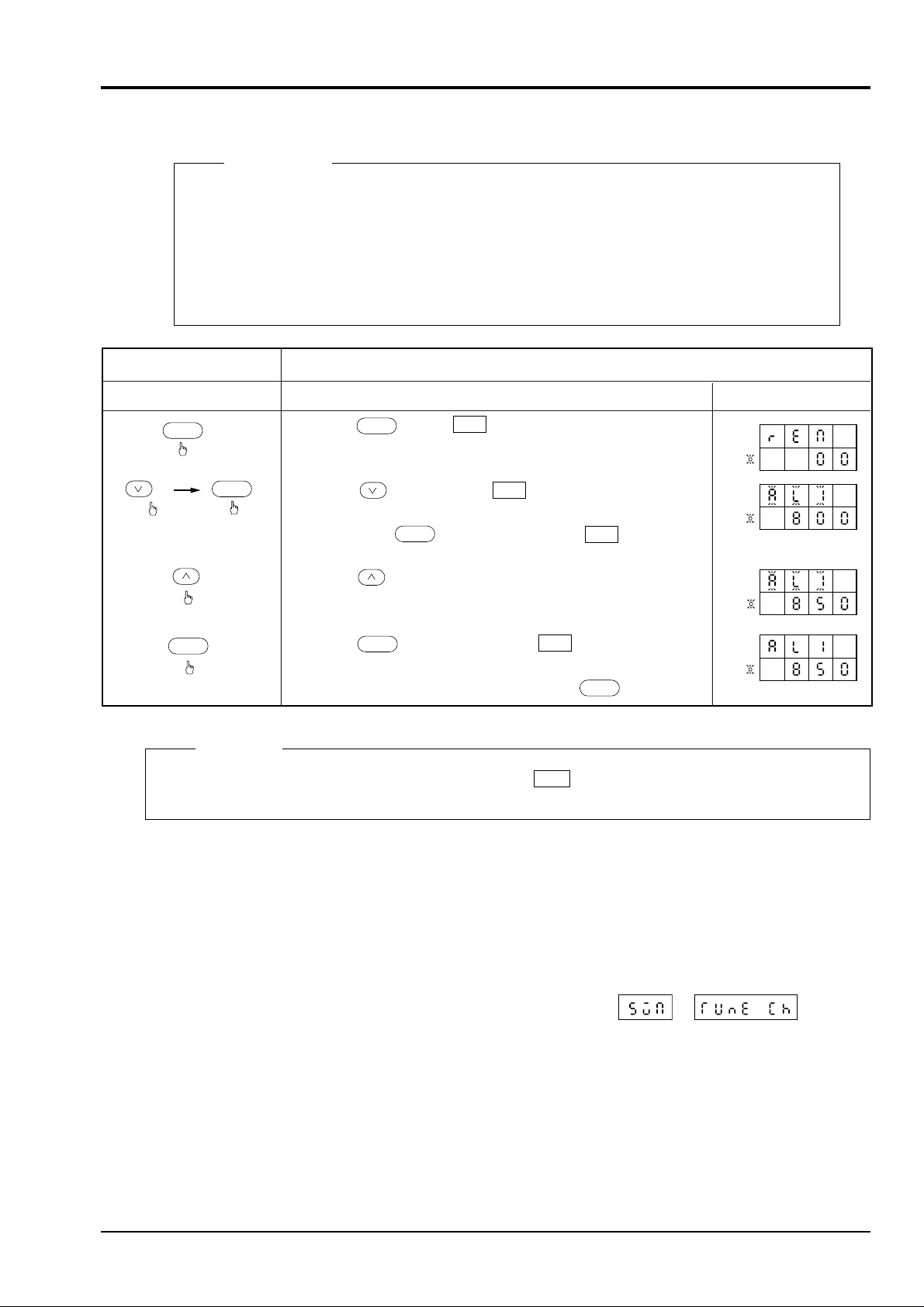
• Press the key for of measured value indication.
• Press the key 3 times for of measured value
indication.
Then press the key. The indication of flickers.
• Press the key to change the data of set value indication from
800 to 850.
• Press the key for registration. stops flickering.
This completes the change of the main alarm 1.
• To reset to the operation indication, press the key.
Contents of operation
Key operation
Change of set value of main alarm 1 from 800°C to 850°C
Description Indication
SEL
SEL
DATA
DATA
PV
SV
PV
SV
PV
SV
PV
SV
3 times
ENT
ENT
REM
AL1
AL1
AL1
SV/MV
(3) Setting of main alarm set value (AL1, AL2)
Description
Set data prior to delivery from the factory are as follows.
Main alarm 1 (AL1): Higher limit deviation alarm; set value is an industrial value of 50% full
scale.
Main alarm 2 (AL2): Lower limit deviation alarm with lower limit hold; set value is an indus-
trial value of 50% full scale.
4. PREPARATION FOR OPERATION, AND OPERATION
(4) Auto-tuning (AT) operation
Remarks
The setting method for AL2 is the same as above. Indicate AL2 referring to “15. parameter list” on page 35
and follow the above procedures.
Auto-tuning is a function to set up the parameter of PID automatically with PYH for operation.
a) Auto-tuning should be performed after setting the set value (SV), main alarm 1 & 2, and proportional cycle
(C1, C2 *1). *1: With control output 2 produced
b) Setting data for auto-tuning
The method of auto-tuning is set up to the standard type prior to delivery from the factory (see (4)- d)). Low
PV type (overshoot suppression) can also be selected by setting 01 in of .
(Refer to “15. Parameter list” on page 35.)
INP-TN3PYH-E 7
Page 14
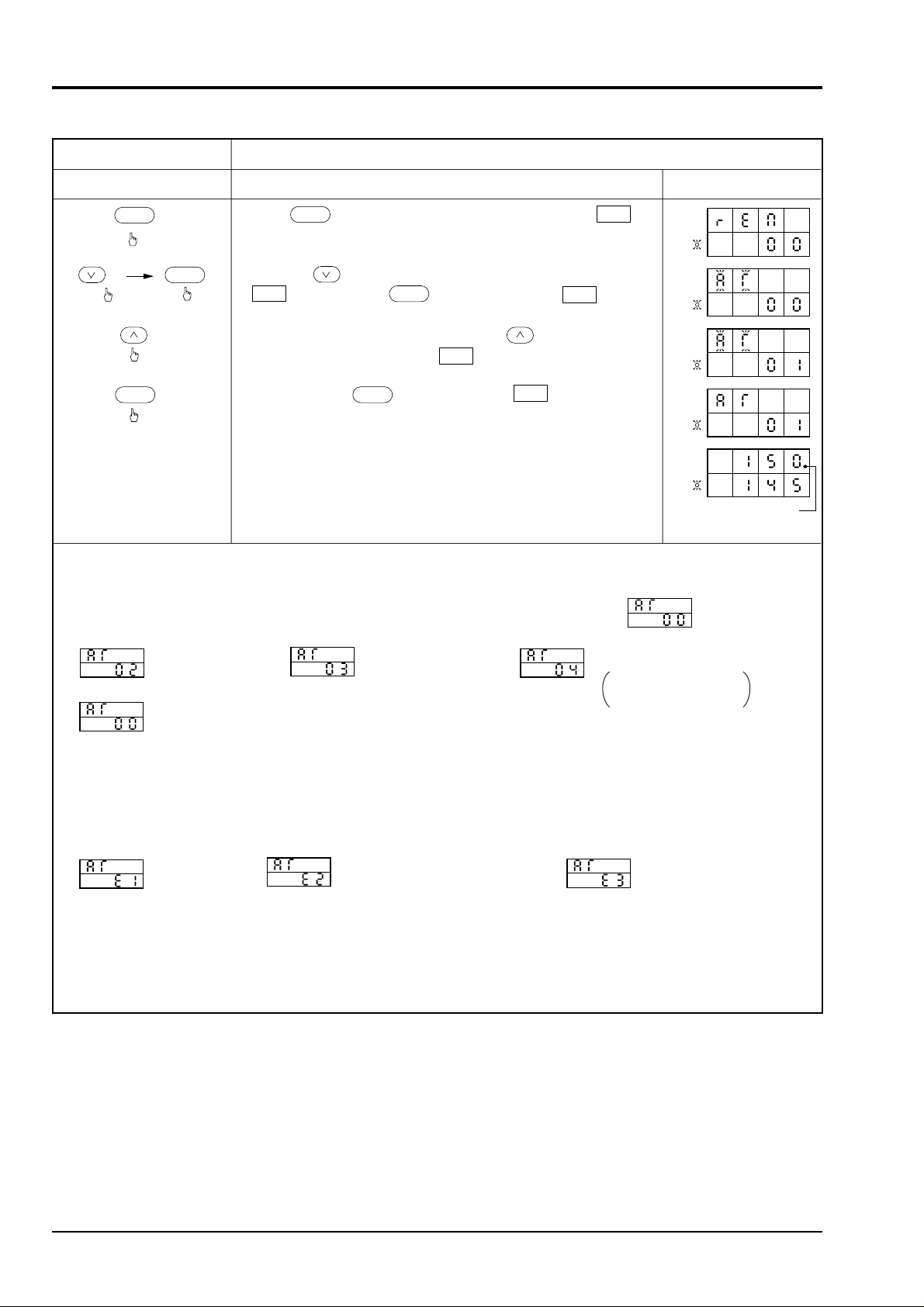
4. PREPARATION FOR OPERATION, AND OPERATION
c) Auto-tuning operation method
Contents of operation
Key operation
SEL
DATA
14 times
ENT ENT
Startup of auto-tuning
Description Indication
• Press key to indicate measured value indication .
SEL
REM
• Press the key 14 times to indicate measured value indication
AT
, then press the key. The indication flickers.
DATA
AT
• When performing auto-tuning, press the key and set the
data of set value indication to .
• By pressing the key, the indication stops flickering
01
AT
and auto-tuning is started.
(The auto-tuning lamp will light in the measured value
indication.)
PV
SV
PV
SV
PV
SV
PV
SV
PV
SV
Auto-tuning
• During auto-tuning, the followings are indicated. When the auto-tuning time is long (about 13 min. or more), the
indication is reset to operation indication automatically while auto-tuning continues.
• The followings are indicated in order during auto-tuning, but it is completed normally at .
at output ON
at output OFF
under calculation
Disappears almost
momentarily
completed normally
lamp
• After checking the completion of auto-tuning, the PID value calculated automatically needs to be registered.
For registration, select PID parameter and follow the procedures in “(5) Setting of PID parameter” on page 9.
At this time, the data indicated is a PID value which has been determined, so it need not be changed.
* If this registration is not made, the controller operates with PID value prior to auto-tuning.
• When auto-tuning is abnormal, the followings are indicated.
time over
PV higher/lower limit check
error (large process response)
change of SV during
auto-tuning
When these indications appear, auto-tuning is not possible. Set the PID value according to “(5) Setting of PID
parameter”.
During auto-tuning, the auto-tuning lamp lights and it goes off when auto-tuning is completed.
(Note) Auto-tuning may require several 10 minutes depending on process response characteristic.
Note 1) During auto-tuning, vibration of process is observed. It is a phenomenon of auto-tuning, which is
stabilized at the completion of auto-tuning.
Note 2) When operating conditions are changed, carry out auto-tuning once again.
Note 3) Do not use auto-tuning for the following processes.
• Process disorder due to temporary ON-OFF control output from PYH is prohibited.
• Pressure or flow process having very quick response.
8 INP-TN3PYH-E
Page 15
4. PREPARATION FOR OPERATION, AND OPERATION
AT in operation
AT in operation
AT end
(PID Setting)
AT end
(PID Setting)
Startup of AT
Startup of AT
Set value (SV)
Set value (SV)
ON 100%
OFF 0%
ON ON
OFF
PV (Measured value)
OFF
ON-OFF operation
ON-OFF operation
PID control
PID control
SV-10%
ON ON
(Control output)
(Control output)
ON 100%
OFF 0%
OFF OFF
When AT lamp lights,
ON-OFF operation
(2-position operation)
is effected and the
measured value (PV)
is oscillated.
PV (Measured value)
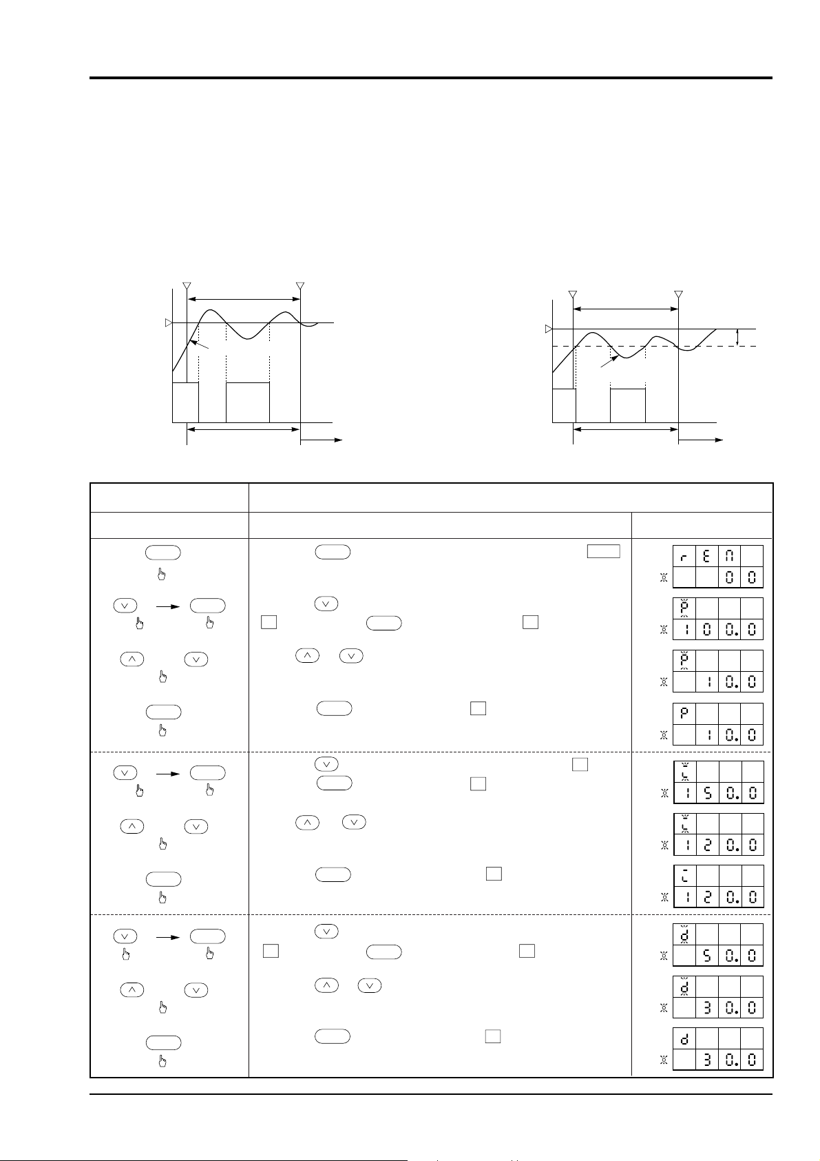
Contents of operation
Key operation
Description Indication
Setting of PID parameter. (Example: P=10, I=120, D=30)
SEL
DATA
DATA
DATA
15 times
ENT
ENT
PV
SV
PV
SV
PV
SV
PV
SV
PV
SV
PV
SV
PV
SV
PV
SV
PV
SV
PV
SV
• Press the key to indicate measured value indication REM .
• Press the key 15 times to indicate measured value indication
P , then press the key. The indication P flickers.
• Press or key to set the data of set value to 10.
• Press the key. The indication P stops flickering.
The value of P is set up.
• Press the key to indicate measured value indication I .
Press the key. The indication I flickers.
• Press or key to set the data of set value to 120.
• Press the key and the indication I stops flickering.
The value of I is now set.
• Press the key once to indicate the measured value indication
D , then press the key. The indication D flickers.
• Press the or key to set the data of set value to 30.
• Press the key and the indication D stops flickering.
The value of D is now set.
SEL
or
DATA
2 times
ENT
or
DATA
DATA
ENT
ENT
or
ENT
d) Auto-tuning comes in two types; q Standard type (with overshoot) and w Low PV type (overshoot suppres-
sion).
The type q is an overshoot where the measured value (PV) exceeds the set value (SV) during auto-tuning. Use
this type when overshoot is allowed.
The type w is for ON-OFF operation with a value lower than the set value (SV) by 10% / full scale.
Use this type when overshoot needs to be suppressed.
(5) Setting of PID parameter
q Standard type (with overshoot)
w Low PV type (overshoot suppression)
INP-TN3PYH-E 9
Page 16

4. PREPARATION FOR OPERATION, AND OPERATION
4.3 Selection of operation mode
(1) Selection of auto/manual operation
• By pressing the
indicated, the device is changed from auto operation to
manual operation. By pressing the key once again, it is
set in auto operation.
(This selection is balanceless/bumpless.)
• During manual operation, the manual operation lamp
M
will light. (During auto operation, the auto opera-
tion lamp A will light.)
• Control output operation during manual operation is
made by pressing the
output and then pressing the key or and
keys. (When changing to control output indication,
is displayed on the manual operation indication. This is
used only for remote operation, so the
be pressed until the manual operation lamp lights.)
Control output operation speed
Normal ( or key only): About 40 s/full
scale
Fast-forward ( and keys, or and
keys): About 8 s/full scale
key when operation mode is
A/M
key to indicate control
SV/MV
SV/MV
key should
Caution
1. When transmission function is
provided, manual operation is possible
from the host system. Setting to make
manual operation invalid is also
possible from the host system. In this
case, the code 01 should be set using
in the item of parameter.
SCE
2. Setting to make A/M mode change
invalid is also possible. (Set the code
01 using in the item of
MIH
parameter.)
Caution
During remote operation, the indicating
R
lamp on the front panel lights.
However, this lamp flickers when R-ACK
signal DI1 (remote check signal) is OFF.
If “A” or “C” is not specified in the 11th
digit of PILC, the instrument will not
operate normally.
Since remote SV indication and so on
may not be displayed correctly, don’t use
it.
• Operation of the
ENT
key for data registration is not required.
10 INP-TN3PYH-E
Page 17

(2) Selection of auto/remote operation
Contents of operation
Key operation
Description Indication
SV balance prior to changing from auto to remote operation
SEL
• Press the key to indicated DSV .
• Press the or key to set the value of DSV to 0.
(Note 1)
This operation is called the balance operation.
• Press the key to reset to operation indication.
PV
SV
PV
SV
PV
SV
or
SV/MV
SV/MV
SV/MV
Contents of operation
Key operation
Description Indication
Remote operation
DATA
DATA
• Press the key to indicate the measured value indication
REM . Press the key, and the indication REM
flickers. The indication of set value 00 means auto operation.
• Press the key to indicate the set value indication 01 ,
then press the key for registration. The indication 01
means remote operation. The remote operation lamp flickers.
Apply an external signal to R-ACK (DI1) digital input signal.
The remote operation lamp stops flickering.
This completes the selection of remote operation. Remote
operation is started with the analog signal from the external
device or the set value (SV) for SV selection.
FLT R A M C1 C2 H L HB
FLT R A M C1 C2 H L HB
SEL
SEL
ENT
ENT
R
R
a) Selection of auto to remote operation
When the controller is to be changed from auto operation with the set value (SV) indicated on the front to
remote operation with analog signal from the external device or set value (SV) for SV selection, the following
procedures should be used.
(This selection is balance/bumpless, so it should be carried out after the following operation.)
4. PREPARATION FOR OPERATION, AND OPERATION
• DSV is a value obtained by subtracting the SV value of cascade input from the SV value which has
been set from the front of PYH.
• During auto operation, the auto operation lamp M on the front will light.
Note 1) In this case, don’t manipulate the
+
or +
keys. SV value changes
suddenly and control may not be performed accurately.
q Selection from auto to remote operation with keys on the front of the main unit
INP-TN3PYH-E 11
Note 1) Remote operation with external analog signal requires R-ACK signal (remote check DI
Note 2) When remote operation is selected with T-link transmission, DI1 and DI3 of the T-link
signal). Use the external terminal DI1 (auxiliary input DI) for this signal (see 14. Connection diagram on page 34).
channel should be set to 01 (see 15. Parameter list on page 35).
Page 18

4. PREPARATION FOR OPERATION, AND OPERATION
w Selection from auto to remote operation with host transmission
This selection is made by instructions from the host system through transmission functions (RS-485, T-link).
For details, refer to the technical instruction manual.
b) Selection from remote to auto operation
When changing the operation mode from remote operation with analog signal from external device or set value
(SV) of SV selection to auto operation with set value (SV) indicated on the front of the controller, the following
procedures should be used.
(This selection is balanceless/bumpless.)
q Selection from remote to auto operation by keys on the front of the main unit
Contents of operation
Key operation
SEL
DATA
ENT
Even when 01 is set in REM , auto operation is effected if R-ACK signal is removed.
w Selection from remote to auto operation with host transmission
This selection is effected by instructions from the host system through transmission functions (RS-485, Tlink).
Clear the remote operation
Description Indication
• Press the key to indicate measured value indication to
REM , then press the key. The indication REM
SEL
DATA
flickers. The set value indication 01 means remote operation.
• Press the key to set the set value indication to 00 . Then,
press the key. The set value indication 00 means auto
operation.
The auto operation lamp lights. Now, the auto operation has
ENT
A
been selected.
* When changing the set value (SV), see item 4.2 (2).
FLT R A M C1 C2 H L HB
FLT R A M C1 C2 H L HB
12 INP-TN3PYH-E
Page 19

5. FAULT INDICATION
Indication Cause
Remedy
FLT lamp is lit.
The contents of FLT light
can be indicated by using
key according to FLT
indication of input/output
data channel.
Manual
operation
Trouble with main unit
Error of DO output setting
Measured value input (PV): Over, under,
burnout
. Resistance bulb sensor is disconnected or
shorted.
. 1 to 5V DC, 4 to 20mA DC input wire is
disconnected or shorted.
. Polarity + ,
-
of the input wire is
reversed.
. Thermocouple sensor is disconnected.
No
Yes
Yes
Yes
Replace the main unit.
Correct the DO output setting
of input/output data channel.
Check measured value input.
Check the wiring of the
measured value input.
Measured value indication
is or .
(Page 36)
Condition
Disconnection
Short-circuit
Indication
Control output
Disconnection of 2
wires or 3 wires
ON or more than 24mA, OFF or more than 0mA
OFF or more than 0mA, ON or more than 24mA
ON or more than 24mA, OFF or more than 0mA
OFF or more than 0mA, ON or more than 24mA
The controller has a fault indicating function so that the cause of fault can be removed quickly.
Note) In the event of a fault, perform manual operation as an emergency measure (see item 4.3 (1)).
If the measured value input is abnormal, it is indicated as shown in the table below where the control output corresponding
to the measured value indication is output.
Resistane bulb input
INP-TN3PYH-E 13
Page 20

5. FAULT INDICATION
Thermocouple outpupt
Disconnection
Short-circuit
1 to 5V DC input
Short-circuit
4 to 20mA DC
Disconnection
Short-circuit
Condition
Condition
Condition
Indication
Indication of
temperature at
shorted point
Indication
Indication
Control output
ON or more than 24mA, OFF or 0mA
Control assuming input as temperature at shorted point
Control output
OFF or 0mA, ON or more than 24mA
Control output
OFF or 0mA, ON or more than 24mA
Note) Control output changes its action by designating burnout direction. This is effected by setting a param-
eter in "brn" (designation of burnout direction) of specification change channel.
14 INP-TN3PYH-E
Page 21

6. USE OF HEATER ALARM (OPTION)
● Heater burnout detect current and heater rated voltage need to be set according to the heater being used. These are
factory set to 100V and 50A, respectively, prior to delivery.
● Alarm operating point should be set by heater alarm current ( ) and heater rated voltage ( ).
● Current detector (CT) comes in 2 types, 0 to 30A type (CTL-6-SF) and 20 to 50 A type (CTL-12-S36-8F). Use either
one that is suited for the heater current being used.
● Setting of alarm set point
When 2 heaters of 2000W/115V are used in parallel and if one is disconnected, the rated current of 34.8A becomes
17.4A. Detection of disconnection should be set in the middle (26.1A) between the rated current and the disconnection current. (The set value of disconnection detection should be more than 15% of the rated current.)
When “N” number of heaters are connected together, the set value should be in the middle between “N” and “N-1”.
● When the heater power is also used for the instrument, the variation of alarm operating point due to power fluctuation
can be minimized.
● This method cannot be used when heaters are controlled by the thyristor phase angle control method.
● In the following power system, heater rated voltage should be 100V AC used for the instrument.
200VAC
Heater
● Connection of heater current detecting CT
Wiring to heater (inserted through CT hole)
Current detector (CT) outline diagram
Transformer
100V AC
PYH
PYH (without polarity)
Type: *CTL-6-SF (1 to 30A)
15
2.11
7.5
φ5.8
25
21
10.5
30
40
INP-TN3PYH-E 15
3
10
φ3.5 × 2
Page 22

● Connection of heater burnout alarm (for Type PYH9)
Power source
85 to 265V AC
6. USE OF HEATER ALARM (OPTION)
MG
SW
13
Power source
14
Control output
25
22
10
11 4 7
12
33
34
Heater burnout alarm output
Magnet switch
Current detector
*CTL
Thermocouple
Heater
Electric furnace
•When the heater capacity is too small and the detector error is large, the sensitivity can be improved by
winding the heater wire twice on the current detector (CT) to make the apparent current two times as large.
•When winding the current detector (CT) with many turns of wire, be sure to wind it in the same direction.
(See the figure below.)
• When the current detector (CT) is wound with many turns, the sensitivity will increase so the setting of
disconnection detecting current needs to be changed (disconnection detection setting = heater rated current ×
number of tuns).
1 turn
2 turns
Type: *CTL-12-S36-8F (20 to 50A)
φ2.36
40
φ12
M3, 4 deep
30
40
7.5
15
16 INP-TN3PYH-E
Page 23

7. CHANGING OF FUNCTIONS
Contents of operation
Key operation
Description Indication
Change of input from J thermocouple to K thermocouple
SEL
SEL
SEL
DATA
DATA
3 times
ENT
ENT
ENT
PV
SV
PV
SV
MV
MV
PV
SV
MV
PV
SV
MV
PV
SV
MV
PV
SV
MV
PV
SV
MV
PV
SV
MV
• Press the key to indicate measured value to REM .
• Press the key to indicate .
• Press the key to indicate PVF .
• Press the key 3 times to indicate PVT , then press the
key. The indication PVT flickers.
(The present input code 05 means J thermocouple.)
• Press the key to change 05 to 06 .
(06 means K thermocouple. For the type of input, refer to the
input code table (Table 1)).
• Press the key for registration. The indication stops
flickering. This completes the change of the type of input.
• Press the key and the key at the same time to indicate
RES . Then press the key. The indication RES flickers.
• Press the key once to indicate 01 , then press the
key to reset the controller.
The display returns to operation indication.
SEL
SYS
CH
•
•
•
At the
same
time
DATA
ENT
DATA
Indications shown in the following pages are required for changing the specification of PYH.
The specifications (functions) of this PYH can be changed by the user, if desired.
To change the functions, refer to “15. Parameter list” on page 35 and “12. Parameter set value list” on page 27, to ensure
correct setting.
CAUTION
PYH’s product type cannot be changed. Never change TYPE CH. on page 36.
After the functions have been changed, the parameters which were set before changing the functions become
invalid or new parameters need to be set. So, the user is requested to understand the functions thoroughly
before changing the functions.
After the functions have been changed, be sure to reset the controller. The method for resetting the controller is shown in
the example of change.
When pressing the
this is not an error.
7.1 Method of changing specifications
ENT
key with the parameter “ ” = 01, all LEDs light for a moment and the output is ON. But,
The following shows the types of measured value input, input range and the types of alarm as examples for change
of specifications.
(1) Selection of input specification (The unit is replaceable only with one of the same type.)
INP-TN3PYH-E 17
Page 24

7. CHANGING OF FUNCTIONS
Table 1 Input code table
Type of
input
A
B
C
Type of input
Resistance bulb
Thermocouple
Tungsten-rhenium (WRe5-26)
Voltage
Voltage
Current
With transmitter power
Current
supply, 4 to 20mA DC
(inverter control type only)
JPt100 (old JIS)
Pt100 (IEC)
J
K
R
B
T
E
S
PR40/20
0 to 10mV DC
0 to 50mV DC
0 to 50mV DC
4 to 20mA DC
*3
*3
*3
*3
*3
*4
Code
01
02
05
06
07
08
09
0A
0B
0C
0D
10
11
0F
0E
Measurable range
-
150 to 400°C
-
150 to 400°C
0 to 1000°C
0 to 1200°C
0 to 1600°C
0 to 1800°C
-
200 to 400°C
0 to 750°C
0 to 1600°C
0 to 1800°C
0 to 2400°C
-
999 to 9999
(Scaling range)
°C
Minimum span *2
50°C
50°C
200°C
200°C
1000°C
1500°C
200°C
200°C
1000°C
1800°C
2400°C
• Range width can be set within the range shown above (Programmable range).
Up to the first decimal place can be indicated *1. (To be used with the span of 1000°C or less.)
• “°C” is based on IEC standards.
• Accuracy
B: 0 to 400°C, ± 5%
R: 0 to 500°C, ± 1%
PR40/20: Less than 1000°C; not guaranteed, more than 1000°C ; ±1%
*1: Voltage/current input is indicated up to the third decimal place.
*2: Range setting below minimum span is out of accuracy assurance.
*3: Inhibit the minus temperature input
*4: 250Ω resistor is built in, and external resistor is not required.
Note) The input range of this table means the range that PYH can measure the input.
This means overrange and underrange should be included in this range. You should set your range including overrange and underrange within the table range.
(2) Change of input (measurement) range
Description
The lower limit (minimum range) and upper limit (maximum range) of measuring range should be set up.
Caution
Measuring range and the type of input are factory-set prior to delivery. When changing the measuring
range and the type of input, other parameters need to be changed.
18 INP-TN3PYH-E
Page 25

q Change of upper/lower limit of measuring range
Contents of operation
Key operation
Description Indication
Change of measuring range from -50 to 100°C to 0 to 200°C
PV
SV
PV
SV
MV
MV
PV
SV
MV
PV
SV
MV
PV
SV
MV
PV
SV
MV
PV
SV
MV
PV
SV
MV
PV
SV
MV
PV
SV
MV
• Press the key to indicate measured value to REM .
• Press the key to indicate .
• Press the key once to indicate PVF , then press the
key. The indication PVF flickers. PVF is the upper
limit of the measuring range.
• Press the key and key at the same time to change 100
to 200.
• Press the key for registration. The indication stops
flickering. This completes the setting of the upper limit of the
measuring range.
• Press the key once to indicate PVB , then press the
key. The indication PVB flickers.
• PVB is the lower limit of the measuring range. Press the
key to change
-
50 to 0.
• Press the key for registration. The indication stops
flickering. This completes the setting of the lower limit of the
measuring range.
• Press the key and the key at the same time to indicate
RES , then press the key. The indication RES flickers.
• Press the key once to indicate 01 , then press the
key to reset the controller.
The indication returns to operation indication.
SEL
SEL
SEL
SEL
DATA
DATA
DATA
DATA
ENT
ENT
ENT
ENT
ENT
ENT
•
•
•
At the
same
time
DATA
DATA
SYS
CH
Press at the
same time to
obtain 200.
Press to obtain 0.
7. CHANGING OF FUNCTIONS
w Measured value full scale (PVF) – measured value base scale (PVb) must be larger than the minimum range width
(deviation alarm setting cannot be performed accurately.)
INP-TN3PYH-E 19
Page 26

7. CHANGING OF FUNCTIONS
(3) Change of alarm operation
Description
The type of main alarm is factory-set prior to delivery as shown below.
Main alarm 1: Upper limit deviation alarm (code 02)
Main alarm 2: Lower limit deviation alarm (code 04) with lower limit hold
Setting of absolute alarm (upper limit) to main alarm 1 and absolute alarm (lower limit) to main alarm 2.
Contents of operation
Key operation
SEL
•
•
•
SEL
7 times
DATA
ENT
DATA
Change of main alarm 1 code 02 to 01 and main alarm 2 code 04 to 08
Description Indication
• Press the key to indicate measured value to REM .
• Press the key to indicate .
• Press the key to indicate PVF , then press the key
7 times. When 1TP is indicated, press the key. The
indication 1TP flickers.
SEL
SEL
SYS
CH
DATA
PV
SV
MV
PV
SV
MV
PV
SV
MV
(The present main alarm 1 code 02 is indicated.)
• Press the key to change main alarm 1 code 02 to 01 .
(Main alarm 1 code is set as shown in the main alarm code table
(see Table 2).)
• Press the key. The indication stops flickering and the
ENT
setting of main alarm 1 is completed.
Next, set main alarm 2.
• Press the key to indicate 2TP , then press the key.
DATA
The indication 2TP flickers.
(The present main alarm 2 code 4 is indicated.)
PV
SV
MV
PV
SV
MV
PV
SV
MV
ENT
At the
same
time
ENT
• Press the key to change main alarm 2 code 04 to 08 .
(Main alarm 2 code is set as shown in the main alarm code table
(see Table 2).)
• Press the key. The indication stops flickering and setting
ENT
of main alarm 2 is completed.
• Press the key and the key at the same time to indicate
RES , then press the key. The indication RES flickers.
• Press the key once to indicate 01 , then press the
DATA
ENT
key to reset the controller.
The indication returns to operation indication.
PV
SV
MV
PV
SV
MV
PV
SV
MV
PV
SV
MV
20 INP-TN3PYH-E
Page 27

Table 2 : Type of main alarm code table
7. CHANGING OF FUNCTIONS
Type of main alarm
Without alarm
Absolute alarm (upper limit)
(Set by absolute value without regard to main setting.)
Absolute alarm (lower limit)
(Set by absolute value without regard to main setting.)
Upper limit deviation alarm
(Set by deviation value of output from main setting.)
Lower limit deviation alarm
(Set by deviation value of output from main setting.)
With lower limit hold*
Lower limit deviation alarm
Upper/lower limit deviation alarm (non-discriminate)
(The value of lower limit and upper limit deviations are
the same.)
With lower limit hold
Upper/lower limit deviation alarm (non-discriminate)
(The values of lower limit and upper limit deviations are
the same.)
Upper/lower limit alarm
(The values of lower limit and upper limit deviations are
the same.)
Absolute alarm (with lower limit hold)
(Set by absolute value without regard to main setting.)
Code
00
01
08
02
03
04
05
06
07
09
Alarm setting
(absolute value)
Deviation
Alarm
setting
Deviation
Alarm
setting
Deviation Deviation
Alarm
setting
Deviation Deviation
Alarm
setting
Deviation Deviation
Alarm
setting
Alarm setting
(absolute value)
Main alarm output
Operation chart
Main setting
(SV)
Main setting
(SV)
Main setting
(SV)
Main setting
(SV)
Main setting
(SV)
Main setting
(SV)
Main setting
(SV)
Main setting
(SV)
Main setting
Alarm setting
(absolute value)
Deviation
(SV)
Alarm
setting
Alarm
setting
Alarm
setting
Alarm
setting
* Lower limit hold is an action not to emit output until the alarm exceeds the lower limit after power is ON.
INP-TN3PYH-E 21
Page 28

8. DUAL OUTPUT CONTROL TYPE
< PYH dual output control >
Dual calculation
MV
proportional band
Cooling side
PC
<C1>
Output 1(heating)
<C2>
Output 2(cooling)
PV
Dead band
calculation
DV DV’
GAP
SV
PiD
calculation
PYH
When the process tends to generate heat of itself, cooling control is required in addition to heating control. Dual output
control is used to control the temperature of such a process. As another example, it is used in the PH control process.
For the dual output control type, the following settings are required.
q MV 2 proportional cycle (to be set according to the type
of cooling side terminal device)
Setting range: 1 to 255 s (factory-set prior to
delivery; contact output 30 s, SSR/
SSC 2 s, not indicated at DC 4 to 20
mA)
Set to
(
w Cooling side proportional band (setting of the propor-
tional band on the cooling side)
Setting range: 0.0 to 3276.0 (factory-set prior to
of operating condition change channel
).
Heating side
Output
50%
Cooling side
proportional band
100%
200%
MV (%)
50%
delivery; 100.0)
Set to of normal operation channel.
e Dead band (used to overlap the heating side propor-
tional band and the cooling side proportional band, or
separate (dead) them from each other.)
Setting range: -50.0 to +50.0% (factory set prior to
delivery; 0.1%)
Set to of normal operation channel.
• Set value of DB is a percentage (%) of MV full
scale.
r Limiter function
• Heating manipulated value upper limit (
• Heating manipulated value lower limit (
• Cooling manipulated value upper limit (
• Cooling manipulated value lower limit (
, , ,
Set to
of auxiliary alarm channel (
)
)
)
)
Heating side
Overlap band
(dB= –50 to 0%)
*4mA and 20mA are output current.
Output denotes both output 1 and output2.
Proportional band P
Output
20mA
4mA
50%
).
Varies with parameter “ ”
Cooling side
MV(%)
Dead band
(dB= 0 to 0%)
22 INP-TN3PYH-E
Page 29

■ Auto-tuning
•For operation, refer to "Auto-tuning operation" on page 7.
•During auto-tuning, the cooling side output is ON-OFF controlled as shown in the diagram below, to obtain
optimum PID and cooling side proportional band (PC).
(Values of I and D are the same for heating/cooling.)
• At the completion of auto-tuning, register the values of PID and PC referring to page 9.
q Standard type (with overshoot)
8. DUAL OUTPUT CONTROL TYPE
AT start
Set value (SV)
Heating side
(control output)
Cooling side
(control output)
ON 100%
OFF 0%
ON 100%
ON
OFF
w Low PV type (overshoot suppression)
AT start
Set value (SV)
AT end (PID setting)
AT under operation
PV (measured value)
ON
OFF
ON
OFF
AT end (PID setting)
AT under operation
OFF
ON
PID control
While AT lamp is lights,
measured value (PV) is
oscillated by ON-OFF
action (2-position action).
SV-10%
PV (measured value)
Heating side
(control output)
Cooling side
(control output)
INP-TN3PYH-E 23
ON 100%
OFF 0%
ON 100%
ON
OFF
OFF
ON
ON
OFF
OFF
ON
PID control
Page 30

9. SV SELECTION
This function is used to control set values (SV) of 1 to 7 types set by the keys on the front of the controller using external
contact input (DI).
Note) The number of set values (SV) varies with the type of PYH.
• For setting the set values (SV1 to SV7), use
Auxiliary input
Digital 1 Digital 2 Digital 3
OFF
ON
OFF
ON
OFF
ON
OFF
ON
Note) All can be used by PYH9 type. Only the item shown in can be used by
PYH7, PYH5 and inverter control types.
Note) When operating PYH with any set value of SV1 to SV7, remote operation is effected. When digital 1, 2
and 3 are at OFF, PYH is set in auto-operation mode using the set value obtained from the front of PYH.
When changing the operation (remote operation) with set values of SV1 to SV7 to auto-operation, the set
values of the remote operation is still valid so they need to be changed.
OFF
OFF
ON
ON
OFF
OFF
ON
ON
to
OFF
OFF
OFF
OFF
ON
ON
ON
ON
of normal operation channel.
Set value
SV0 (Auto-operation is effected.)
SV1
SV2
SV3
SV4
SV5
SV6
SV7
24 INP-TN3PYH-E
Page 31

10. POSITION FEEDBACK CONTROL TYPE
Contents of operation
Key operation
Description Indication
DATA
DATA
DATA
DATA
DATA
ENT
ENT
ENT
ENT
ENT
ENT
ENT
ENT
PV
SV
MV
PV
SV
MV
PV
SV
MV
PV
SV
MV
PV
SV
MV
• Set the valve opening to 0%, then set 01 to the data.
• Press the key. When the indication is changed from 01 to
00, zero point has been adjusted.
• Next, set the valve opening to 100%, then set 02 to the data.
• Press the key and when the indication is changed from
02 to 00, adjustment at 100% point is completed.
• Next, press the key once to indicate FIX , then press the
key.
Example of tuning
of 100% point
Example of tuning
of 0% point
• Finally, press the key to indicate RES , then press the
key to indicate 01 . Press the key to reset the
controller.
The indication returns to operation indication.
PV
SV
MV
PV
SV
MV
• Press the key once to indicate 01 . Then, press the
key and when the indication is changed from 01 to 00,
registration is completed.
DATA
Position feedback control is a function to control by feeding back valve opening signal with a motor-driven valve connected to a terminal device.
• To adjust zero and span of valve opening signal (potentiometer), call the specification change channel (SYS CH.)
to select the item of POT and use the following procedures.
Note) Valve opening indication
Accuracy: ± 0.2% FS
Resolution: max. ± 1.0% FS
INP-TN3PYH-E 25
Page 32

11. INVERTER CONTROL TYPE
Inverter control is a control system with inverter used for terminal device. In the inverter control type, transmitter power
supply built in PYH is also available.
This controller is able to select frequency indication in addition to normal operation indication (PV/SV indication).
1. Selection of frequency indication
SV/MVSV/MVSV/MV
Frequency
SV/MV
SEL
Setting of full scale
Setting of base scale
PV
SV
PV
SV
PV
SV
SEL
Setting of decimal point
DATA
ENT
Note) MV output is not stabilized for the time (FLT output) until it is raised a few seconds after power for
PYH is closed.
2. On the scale value setting of frequency indication, the following is factory-set prior to delivery.
• Full scale (MVF) : 600
•Base scale (MVB) : 0
• Decimal point (MVD) : 01
When changing, use procedures as shown above.
Note) Frequency is indicated down to MV = -25%, so it may be indicated in negative value.
3. Connection to pressure transmitter
• Connection to FC series pressure transmitter (FBC)
0+
0––+65
•Connection to FCX pressure transmitter (FHG) or small type pressure sensor (FCP)
–
–
+
+65
PYH
PYH
26 INP-TN3PYH-E
Page 33

12. PARAMETER SET VALUE TABLE
Channel
Indication
REM
SCE
LOC
AL1
AL2
HBA
HBV
SV1
SV2
SV3
SV4
SV5
SV6
SV7
AT
P
PC
I
D
GAP
PGP
DB
PAS
PSS
Remote mode
SCC operation
Setting lock
Main alarm 1 setting *
Main alarm 2 setting *
Heater burnout setting
Heater rated voltage
SV select type
SV setting 1 *
SV select type
SV setting 2 *
SV select type
SV setting 3 *
SV select type
SV setting 4 *
SV select type
SV setting 5 *
SV select type
SV setting 6 *
SV select type
SV setting 7 *
Auto-tuning start
Proportional band
Cooling side proportional
band
Integral time
Derivative time
Dead band *
Position feedback dead band
Dead band
Pass board
Pass code
Setting range
Name/item
Preset
value
Remarks
Entry
column
00: Auto-operation
01: Remote operation
00: Inhibit
01: Acceptable
00: Parameter setting
possible
01: Parameter setting
not possible
02: Setting other than
SV not possible
-
25.0 to 125.0
-
25.0 to 125.0
0 to 50A
0 to 300V
-
25.0 to 125.0
-
25.0 to 125.0
-
25.0 to 125.0
-
25.0 to 125.0
-
25.0 to 125.0
-
25.0 to 125.0
-
25.0 to 125.0
00: None
01: Start
0.0 to 3276%
0.0 to 3276%
0.0 to 3276 s
0.0 to 900.0 s
0.0 to 100.0
0.0 to 100.0%
-
50.0 to 50.0%
0000 to FFFF
0000 to FFFF
Upper limit deviation
(preset)
Lower limit deviation with
hold (preset)
Indicated only for heater
burnout alarm type.
Indicated only for heater
burnout alarm type.
1) Used for SV select type.
2) Indicated only for SV
select type.
3) SV1 to SV7 setting
possible for PYH9 type
4) SV1 to SV3 setting
possible for PYH5/7 type
0.0 for ON/OFF control
Indicated only for dual
output type.
00 not integrated
(2-position type or P action)
Indicated only for position
feedback type.
Indicated only for dual
output type.
Normal operation channel
00
00
00
50
50
50A
100V
0
0
0
0
0
0
0
00
0.5%
0.5%
3276 s
0.0 s
0.0
3.0%
0.1%
0000
0000
on page 4 lights
with “01”.
20
(Note) * can be set in industrial values.
Setting range is shown in industrial value %.
Example) For 0 to 400°C range, 0 is 0°C and 100 is 400°C.
INP-TN3PYH-E 27
Page 34

12. PARAMETER SET VALUE TABLE
Channel
Auxiliary alarm channel
Indication
DH
DHS
DL
DLS
SH
SL
PH
PHS
PL
PLS
PHH
HHS
PLL
LLS
MH
ML
HMH
HML
CMH
CML
MHA
MHS
MLA
MLS
DPV
DMV
Name/item
Deviation (+) alarm *
Deviation (+) alarm
hysteresis *
Deviation (-) alarm *
Deviation (-) alarm
hysteresis *
Set value upper limit *
Set value lower limit *
Measured value upper limit
alarm *
Measured value upper limit
alarm hysteresis *
Measured value lower limit
alarm *
Measured value lower limit
alarm hysteresis *
Measured value upperupper limit alarm *
Measured value upper-upper
limit alarm hysteresis *
Measured value lowerlower limit alarm *
Measured value lower-lower
limit alarm hysteresis *
Manipulated value (MV)
upper limit
Manipulated value (MV)
lower limit
Heating manipulated value
lower limit
Heating manipulated value
lower limit
Cooling manipulated value
upper limit
Cooling manipulated value
lower limit
Manipulated value (MV)
upper limit alarm
Manipulated value upper
limit alarm hysteresis
Manipulated value lower
limit alarm
Manipulated value lower
limit alarm hysteresis
Measured value variation
rate alarm *
Manipulated value variation
rate alarm
Setting range
0.0 to 100.0
0.0 to 100.0
0.0 to 100.0
0.0 to 100.0
-
25.0 to 125.0
-
25.0 to 125.0
-
25.0 to 125.0
0.0 to 100.0
-
25.0 to 125.0
0.0 to 100.0
-
25.0 to 125.0
0.0 to 100.0
-
25.0 to 125.0
0.0 to 100.0
-
25.0 to 125.0%
-
25.0 to 125.0%
-
25.0 to 125.0%
-
25.0 to 125.0%
-
25.0 to 125.0%
-
25.0 to 125.0%
-
25.0 to 125.0%
0.0 to 100.0 %
-
25.0 to 125.0%
0.0 to 100.0%
0.0 to 100.0
0.0 to 100.0%
Preset
value
100.0
100.0
100.0
100.0
125.0
-
25.0
125.0%
-
25.0%
125.0%
-
25.0%
125.0%
-
25.0 %
125.0%
0.0%
-
25.0 %
0.0%
100.0
100.0%
0.0
0.0
0.0
0.0
0.0
0.0
0.0
0.0
Entry
column
Remarks
Set PL < PH.
If PL>PH, the device is not
operated properly.
Set PL < PH.
If PL>PH, the device is not
operated properly.
Indicated only for dual
}
output type.
28 INP-TN3PYH-E
Page 35

12. PARAMETER SET VALUE TABLE
Channel
Indication
TF
KNL
CUT
DT
REV
ARH
ARL
TON
Operating condition change channel
TOFF
EXM
C1
C2
MAN
Name/item
Measured value filter time
constant
Non-linear gain
Router cut point
Sampling cycle
Reverse action setting
Integration cut point upper
side *
Integration cut point lower
side *
Intermittent PID
(with control)
Intermittent PID
(without control)
EXT-MV setting
MV 1 proportional cycle
MV 2 proportional cycle
Manual reset
Setting range
10.0 to 900.0 s
0.0 to 327.7%
-
25.0 to 125.0%
0.1 to 3276 s
00: Normal 01: Reverse
0.0 to 125.0
0.0 to 125.0
0 to 9999 s
0 to 9999 s
-
25.0 to 125.0%
1 to 255 s
1 to 255 s
-
25.0 to 125.0%
Preset
value
10 s
0.0%
-
0.01%
0.1 s
Reverse: 01
100.0
100.0
0 s
0 s
0.0%
Relay contact
output 30 s,
SSR/SSC
drive output
2 s.
0.0%
Entry
column
Remarks
When the router is unused,
set PV to –0.01%. When
input is made from resistance
bulb or thermocouple, be
sure to set PV to –0.01%.
Setting of industrial
value for set value (SV)
Indicated only for dual output
type.
Effective only when I = 0.0.
PVF
PVB
PVD
PVT
PVU
Specification change channel
SFT
AOT
1TP
2TP
Measured value full scale
Measured value base scale
Measured value decimal
point position
PV input type
PV unit
PV zero shift *
AO output type
Main alarm 1 type
Main alarm 2 type
Input range upper
limit setting
Input range lower
limit setting
00: Without decimal
point
01: 2nd digit from end
02: 3rd digit from end
03: 4th digit from end
See page 17.
00: °C 02: Other
-
50.0 to 50.0
00: Measured value
(PV) output
01: Set value
(SV) output
02: Control output
value (MV) output
See page 17.
See page 17.
Specified
when
ordering
Specified
when
ordering
Specified
when
ordering
Specified
when
ordering
Specified
when
ordering
0.0
0.0
02
04
00 and 01 only for
thermocouple and resistance
bulb
02: Upper limit deviation
04: Lower limit deviation
with hold
1HS
2HS
INP-TN3PYH-E 29
Main alarm 1 hysteresis *
Main alarm 2 hysteresis *
0.0 to 100.0
0.0 to 100.0
0.0
0.0
Page 36

12. PARAMETER SET VALUE TABLE
Channel
Specification change channel
Indication
MVF
MVB
MVD
RIH
SIH
MIH
CND
BRN
Name/item
Manipulated value full scale
Manipulated value base
scale
Manipulated value decimal
point position
Remote setting indication
inhibit
SCC setting indication
inhibit
A/M mode change inhibit
Startup control condition
Burnout direction
Setting range
-
999 to 9999
-
999 to 9999
00: Without decimal
point
01: 2nd digit from end
02: 3rd digit from end
03: 4th digit from end
00: Release
01: Inhibit
00: Release
01: Inhibit
00: Release
01: Inhibit
00: Automatic
01: Manual
00: Hold
Lower limit scale out
01:
02:
Upper limit scale out
Preset
value
600
0
01
Specified
when
ordering
Specified
when
ordering
00
00
01
Entry
column
Remarks
Indicated only for inverter
control type.
With external set value
input, T -link transmission
and SV select: 00
Without above: 01
Not specified: 00
Designation of manipulated
out (MV) burnout direction
RS485
transmission channel
Potentiometer zero/span
POT
adjustment
Trace fix command
FIX
Reset command
RES
Station No.
STN
Transmission speed
SPD
Bit format
BIT
00: No adjustment
01:
Zero point adjustment
02:
Span point adjustment
01 registered for
adjustment of
potentiometer
01 registered when
changing parameters
other than SYS CH
00 to FF
03: 9600 BPS
04: 19200 BPS
01: No-parity stop bit 1
02: No-parity stop bit 2
11: Parity odd number
stop bit 1
12: Parity odd number
stop bit 2
21: Parity even number
stop bit 1
22: Parity even number
stop bit 2
00
00
00
01
03
01
Indicated only for position
feedback type.
Hexadecimal setting
Connected to transmission
interface board.
(type PYY): 04
Connected to transmission
interface board.
(type PYY): 12
30 INP-TN3PYH-E
Page 37

12. PARAMETER SET VALUE TABLE
Channel
T-link
transmission channel
Indication
MOD
STN
TEM
DI1
DI2
DI3
Name/item
T-link operation mode
Station address
EX-MV T-link setting
DI1 T -link setting
DI2 T -link setting
DI3 T -link setting
Table 3. Types of auxiliary alarm outputs
Setting range
00: 8W (PYH mode)
01: 4W (PYK mode)
00 to FF
00: Use main unit data.
01: Use T-link transmi ssion data.
00: Settable from main
unit
01: Settable through
T-link
00: Settable from main
unit
01: Settable through
T-link
00: Settable from main
unit
01: Settable through
T-link
Preset
value
00
01
00
00
00
00
Entry
column
Remarks
Hexadecimal setting
Code
10
11
12
13
14
15
16
17
1A
1B
1C
1D
Type
SV-H (Set value upper limit alarm)
SV-L (Set value lower limit alarm)
PV-H (Measured value upper limit alarm)
PV-L (Measured value lower limit alarm)
PV-HH (Measured value upper-upper limit alarm)
PV-LL (Measured value lower-lower limit alarm)
DV-H (Deviation "+" side alarm)
DV-L (Deviation "-" side alarm)
MV-H (Manipulated output upper limit alarm)
MV-L (Manipulated output lower limit alarm)
DMP (Manipulated variable variation rate alarm)
DPV (Measured value variation rate alarm)
INP-TN3PYH-E 31
Page 38

12. PARAMETER SET VALUE TABLE
Channel
Output terminal define channel
Indication
DO1
DO2
DO3
M
H
HLP
L
LLP
HB
HBL
C1L
C2L
Name/item
DO1 output setting
DO2 output setting
DO3 output setting
AL1 terminal output
setting
H lamp setting
AL2 terminal output setting
L lamp setting
HB terminal output setting
HB lamp setting
C1 lamp setting
C2 lamp setting
Setting range
00 to FF
00 to FF
00 to FF
00 to FF
00 to FF
00 to FF
00 to FF
00 to FF
00 to FF
00 to FF
00 to FF
Preset
value
12: PV-H
13: PV-L
16: DV-H
1E: Main
alarm 1 output
Indication of
above output
1F: Main
alarm 2 output
Indication of
above output
0D: Heater
burnout alarm
output
Indication of
above output
5F
5E
Entry
column
Remarks
See Table 3 for code
symbols.
SVM
PID
STM
GAP
TMX
CMV
A.L
Auto-tuning define channel
A.P
A.D
SV mode
PID selection
Start mode
Auto-tuning dead band
Maximum standby time
Cooling side output setting
Indication of L value after
tuning
Indication of P value after
tuning
Indication of I value after
A.I
tuning
Indication of D value after
tuning
00: Standard type
(SV value 100%)
01: Low PV type
(SV value -10%)
00: PI 01: PID
Auto-tuning not
00:
started at power ON
01:
Auto-tuning started
at power ON
0.0 to 100%
0.0 to 9999 min.
-
25.0 to 125.0%
00
01
00
0.3%
720 min.
100.0%
32 INP-TN3PYH-E
Page 39

13. OUTLINE DIMENSIONS AND PANEL CUTOUT
■ PYH7/PYH9 type
A12150
10
C1
MA
FLT HB
PV
SV
B
MV
SV/MV
A/M
R
SEL DATA ENT
LH
C2
■ PYH5 type
Panel cutout
Note 3)
Type
PYH7 PYH9
Min. 30
A72 96
B91 115
C Min. 92 Min. 116
D Min. 82 Min. 100
E68
+0.7
0
0
+0.8
92
48
PV
SV
96
MV
115
DATA
SEL
SV/MV
A/M ENT
C
12 150
Q'ty 23456
a93141 189 237 285
(When two or more controllers are
mounted together and used at power
supply of 200 to 265V AC, provide a
fan for ventilation.
Also, when a single controller is used
or two or more controllers are mounted
on top of one another, provide a fan.)
D
Panel cutout
Note 3)
Min.
Min.
30
60
Min. 150
45+
Note 3)
Min. 30
Note 3)
Min.
30
0.6
0
E
Note 3)
Min.
30
0.8
0
92+
a+
0.8
0
10
Note 3)
Min.
30
0.8
92+
0
Note 1) Panel is 1 to 8mm thick.
Note 2) Two or more controllers can be mounted togather side by side. When it is mounted on top of one
another, it requires fixtures, and a minimum size shown in the above diagram must be maintained.
Note 3) Allow a space of more than 30mm to both sides of the controller when mounting a device with a long
depth.
INP-TN3PYH-E 33
Page 40

14. CONNECTION DIAGRAM
PYH9 type
For transmitter
power source
(see page 26)
+
0-
5
(FBC)
–
6
0+
I–
(min)
Potentiometer input
PYH7 type
Open
3
Control output
Close
4
6
1
3
4
6
(position feedback type)
Common
+
Control output 1,
4 to 20mA DC or
–
SSR/SSC drive output
+
Control output 2,
4 to 20mA DC or
–
SSR/SSC drive output
Transmission
RS485
Input
signal
(PV)
External set value input
External transmision output
I+
(max)
Io
Note 4)
Earth
Power source
(85 to 265V AC)
Shield
+
–
CT input
Control output 1
(relay contact outpupt)
Control output 2
(relay contact outpupt)
+
1
–
2
3
4
A
5
B
6
B
7
–
8
+
9
+
10
11
12
13
14
TRX1
TRX2
SHLD
PV1
PV2
PV3
SC
CAS
AO
I+/CT
IO/CT
G
AC
AC
Earth
Power source
(85 to 265V AC)
DO2
DO3
DI3
DIOC
15
16
T1
17
T2
18
SD
19
20
21
22
23
1
2
3
4
5
6
7
8
9
SC
SC
+
–
Shield
Auxiliary alarm 2
Auxiliary alarm 3
Auxiliary DI3 input
C10
C1C
C1
common
C20
C2C
C2
common
G
AC
AC
Transmission
T-link
TRX1
TRX2
SHLD
PV1
PV2
PV3
SC
CAS
AO
I+/CT
IO/CT
C1 common
C2 common
DIOC
+
10
–
11
Shield
12
13
14
15
16
17
18
19
20
+
A
B
B
–
External set value input
–
External transmission output
+
+
I
CT input
C10
C1C
C20
C2C
ALM1
ALM2
HB
ALMC
FLT
DO1
DI1
DI2
Transmission
RS485
Input signal
I+(max)
0
Potentiometer
SC
24
Signal common
25
26
27
28
29
30
31
32
33
Heater burnout alarm outpupt
34
35
36
37
Auxiliary DI1 input
38
Auxiliary DI2 input
39
(PV)
I–(min)
input
Note 4)
Control output 1
(relay contact outpupt)
Control output 2
(relay contact outpupt)
Main alarm 1 output
Main alarm 2 output
Fault output
Auxiliary alarm 1
SC
DO1
DI1
DI2
DIOC
FLT
ALM1
ALM2
HB
ALMC
Open
27
28
30
25
37
28
30
21
22
23
24
25
26
27
28
29
Heater burnout alarm outpupt
30
31
Control output
Close
(position
feedback type)
Common
+
Control output 1,
4 to 20mA DC or
–
SSR/SSC drive output
+
Control output 2,
4 to 20mA DC or
–
SSR/SSC drive output
Auxiliary alarm
Auxiliary DI1 input
Auxiliary DI2 input
Fault output
Main alarm 1 output
Main alarm 2 output
PYH5 type
+
1
Shield
TRX1
2
TRX2
3
SHLD
4
PV1
A
5
PV2
B
6
PV3
B
7
SC/I–
–
8
CAS
+
9
AO
+
10
I+/CT
11
IO/CT
12
G
13
AC
14
AC
DIOC
Transmission
RS485
Input signal
I–(min)
External set value input
External transmission output
Potentiometer input
(PV)
Note 4)
Power source
+
+
–
–
I+ (max)
0
I
CT input
Earth
(85 to 265V AC)
The connecting terminal No. varies with each type
of controller.
For details, refer to the terminal nameplate attached
to the terminal block. Make sure the connection is
correct.
C10
C1C
C1 common
C20
C2C
C2 common
ALM1
ALM2
HB
ALMC
FLT
DO1
DI1
DI2
Signal common
15
SC
16
17
18
19
20
21
22
23
Heater burnout alarm outpupt
24
ALM common
25
26
27
28
29
Auxiliary DI2 input
30
Control output 1
(relay contact outpupt)
Control output 2
(relay contact outpupt)
Main alarm 1 output
Main alarm 2 output
Auxiliary alarm output
Auxiliary
DI1 input
Fault output
18
19
21
16
18
19
21
Open
Close
Common
+
Control output 1,
4 to 20mA DC or
–
SSR/SSC drive output
+
Control output 2,
4 to 20mA DC or
–
SSR/SSC drive output
Control output
(position feedback type)
Note 1) Power fuse is not provided, so external protective
circuit should be used.
Note 2) The G terminal must be grounded to the earth.
Note 3) Do not use the blank terminals.
Note 4) Wires for the potential input signal, thermocouple
input and resistance bulb input must be connected
directly to the PYH main unit terminals.
34 INP-TN3PYH-E
Page 41

15. PARAMETER LIST
PV
SV
SV set by up key
and down
key .
SV/MV
SEL
(Note 1)
(Note 1)
(Note 2)
(Note 2)
(Note 2)
(Note 2)
(Note 2)
Remote mode
00 : Auto operation
01 : Remote operation
SCC enable
00 : Inhibit 01 : Acceptable
Setting lock
00 : None 01 : All lock
02 : Lock excluding SV
Main alarm 1 setting
-25 to125
Main alarm 2 setting
-25 to 125
Heater burnout alarm setting
0.0 to 50.0A
Heater rated voltage
0 to 300V
SV select set value 1
-25 to 125
SV select set value 2
-25 to 125
SV select set value 3
-25 to 125
SV select set value 4
-25 to 125
SV select set value 5
-25 to 125
(Note 2)
SV select set value 6
-25 to 125
(Note 2)
SV select set value 7
-25 to 125
Auto-tuning start
00 : Release 01 : Start
Proportional band
0.0 to 3276%
(Note 5)
Cooling proportional band
0.0 to 3276%
Integral time
0.0 to 3276% s
Derivative time
0.0 to 900.0 s
Dead band
0.0 to 100.0
(Note 4)
Position feedback
Dead band
0.0 to 100.0%
(Note 5)
Dead band
-50.0 to 50.0%
Pass code (memory No.)
0000 to FFFF
Pass code (memory No.)
0000 to FFFF
<Operation condition change channel><Auxiliary alarm channel><Normal operation channel>
SEL SEL SEL SEL
Deviation (+) alarm setting
0.0 to 100.00
Deviation (+) alarm
hysteresis setting
0.0 to 100.00
Deviation (-) alarm setting
0.0 to 100.00
Deviation (-) alarm
hysteresis setting
0.0 to 100.00
Set value upper limit
-25.0 to 125.0
Set value lower limit
-25.0 to 125.0
Measured value upper limit alarm setting
0.0 to 100.00
Measured value upper limit
alarm hysteresis setting
0.0 to 100.00
Measured value lower limit alarm setting
-25.0 to 125.0
Measured value lower limit
alarm hysteresis setting
0.0 to 100.00
Measured value upper-upper
limit alarm setting
-25.0 to 125.0
Measured value filter time constant
0.0 to 900.0 s
Non-linear gain
0.0 to 327.7%
Router cut point
-25.0 to 125.0%
Sampling cycle
0.0 to 3276 s
Reverse action setting
00 : Normal 01 : Reverse
Integration cut point upper side
0.0 to 125.0
Integration cut point lower side
0.0 to 125.0
Intermittent PID (with control)
0 to 9999 sec.
Intermittent PID (without control)
0 to 9999 sec.
EXT-MV setting
-25.0 to 125.0%
(Note 8)
MV1 proportional cycle
1 to 255 sec.
(Note 5)
(Note 8)
MV2 proportional cycle
1 to 255 sec.
Basic operation of keys
• For fast-forward/backward, press the key or key and key
at the same time.
• When calling an item to change data, press the key. The item
DATA
indication flickers. Data should be set thereafter.
Registration of new data
• New SV value is registered automatically without pressing the
ENT
key.
• When changing data from normal operation channel to the operating
condition change channel, press the key to register the data.
ENT
• When changing data from specification change channel to input/output
information channel, press the key, then change the specification
change channel to RES = 1, and press the key to register the
ENT
ENT
data. After registration, all LED light up for a moment and output is
ON. But, it is not an error.
*1 : Setting range in industrial value %.
Item indication varies with specifications
(Note 1) Indication only for heater burnout alarm type
(Note 2) Indication only for SV select type
(Note 3) Indication only for inverter control type
(Note 4) Indication only for position feedback control type
(Note 5) Indication only for dual control type
(Note 6) Indication only for transmission function RS-485
(Note 7) Indication only for transmission function T-link type
(Note 8) Indication of contact or SSR drive output
Measured value upper-upper
upper limit alarm hysteresis setting
0.0 to 100.00
Measured value lower-lower
limit alarm setting
-25.0 to 125.0
Measured value lower-lower
limit alarm hysteresis
setting
0.0 to 100.00
Manipulated value upper limit
-25.0 to 125.0%
Manipulated value lower limit
-25.0 to 125.0%
Heating manipulated value
upper limit
-25.0 to 125.0%
Heating manipulated value
lower limit
-25.0 to 125.0%
(Note 5)
Cooling manipulated value
upper limit
-25.0 to 125.0%
Manual reset
-25.0 to 125.0%
(Note 5)
Cooling manipulated
value lower limit
-25.0 to 125.0%
Manipulated value
upper limit alarm
setting
-25.0 to 125.0%
To * mark on
Page 36
INP-TN3PYH-E 35
Page 42
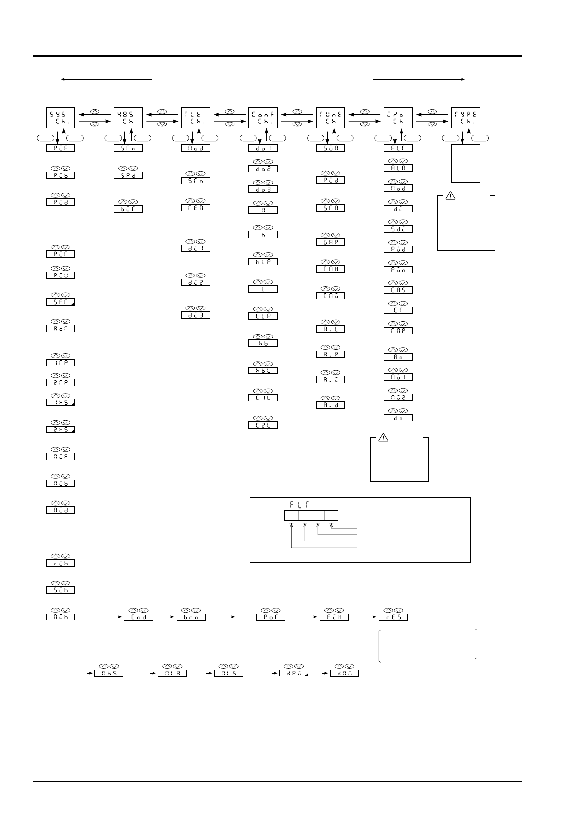
15. PARAMETER LIST
<Specification change
channel>
<RS-485 (Note 6)
transmission channel>
When changing data in SYS CH and subsequent,
reset the contents of parameters displayed in industrial value
<T-link (Note 7)
transmission channel>
<Output terminal
define channel>
<Auto-tuning define
channel>
<Input/output data
channel>
SEL SEL SEL SEL SEL SEL SEL SEL SEL SEL SEL SEL SEL SEL
Measured value full scale
-999 to 9999
Measured value base scale
-999 to 9999
Measured value decimal
point position
00 : Without decimal point
01 : 2nd digit from end
02 : 3rd digit from end
03 : 4th digit from end
PV input type
PV unit
00 : °C 02 :
Other
PV zero shift
-50.0 to 50.0
AO output type
00 : PV output 01 : SV output
02 : MV output
Main alarm 1 type
Main alarm 2 type
Main alarm 1 hysteresis
0.0 to 100.0
Main alarm 2 hysteresis
0.0 to 100.0
Manipulated value full scale
-999 to 9999
Manipulated value base scale
-999 to 9999
Manipulated value decimal
point position
00 : Without decimal point
01 : 2nd digit from end
02 : 3rd digit from end
03 : 4th digit from end
Remote setting indication inhibit
00 : Release 01 : Inhibit
(Note 3)
(Note 3)
(Note 3)
Station No.
00 to FF
Transmission speed
03 : 9600BPS
04 : 19200BPS
Bit format
01 : No-parity stop bit 1
02 : No-parity stop bit 2
11 : Parity odd number
stop bit 1
12 : Parity odd number
stop bit 2
21 : Parity even number
stop bit 1
22 : Parity even number
stop bit 2
T-link operation mode
00 : 8W (PYH mode)
01 : 4W (PYK mode)
Station address
00 to FF
EX-MV T-link setting
00 : Main unit data use
01 : T-link transmission
data use
DI1 T-link setting
00 : From main unit
01 : From T-link
DI2 T-link setting
00 : From main unit
01 : From T-link
DI3 T-link setting
00 : From main unit
01 : From T-link
DO1 output setting
DO2 output setting
DO3 output setting
AL1 terminal output setting
00 to FF
H lamp setting
00 to FF
AL2 terminal output setting
00 to FF
L lamp setting
00 to FF
HB terminal output setting
00 to FF
HB lamp setting
00 to FF
C1 lamp setting
00 to FF
C2 lamp setting
00 to FF
(Note 9)
SV mode
00 : Standard type
01 : Low PV type
PID selection
00 : P1 01 : PID
Start mode
00 : Standard
01 : Start at power ON
Auto-tuning dead band
0.0 to 100.0%
Max. standby time
0.0 to 9999 min
Cooling side output
setting
-25.0 to 125.0%
Indication of L value
after AT
Indication of P value
after AT
Indication of I value
after AT
Indication of D value
after AT
(Fault indication)
(Note 9)
Fault indication
Alarm indication
Control mode
Digital input value
Soft digital input value
PV1
PV2
AI 1
AI 2
Cooling point
compensation temperature
AO output value
MV1 output
MV2 output
DO output
CAUTION
This I/O channel
is a parameter for
“reading only”,
and cannot be set.
1 (FLT status)
2 (T-link down)
4 (Input over/under error)
8 (DO output setting error)
(Main unit fault)
Data
indication
for
product
type. etc.
CAUTION
Never manipulate
Type Ch, or the
instrument may
not be operated
properly.
SCC setting indication inhibit
00 : Release 01 : Inhibit
A (-) M mode change inhibit
00 : Release 01 : Inhibit
From Page 35*
Manipulated value
upper limit alarm
hysteresis setting
0.0 to 100.0%
Startup control
condition
00 : Auto-startup
01 : Manual startup
Burnout direction
setting
00 : Hold
01 :
Lower limit over scale
02 : Upper limit over scale
Manipulated value
lower limit alarm
setting
-25.0 to 125.0%
(Note 4)
Potentiometer zero/span
adjustment
00 : None 01 : Zero
02 : Span
Manipulated value
lower limit alarm
hysteresis setting
0.0 to 100.0%
Command
(used for POT write)
00 : 01 : FIX start
Measured value
change rate alarm
setting
0.0 to 100.0%
Manipulated value
change rate limit
setting
0.0 to 100.0%
Reset command
When changing the contents of parameters in SYS CH and other channels,
be sure to press the reset key for
registration (power ON/OFF is also
available).
36 INP-TN3PYH-E
Page 43
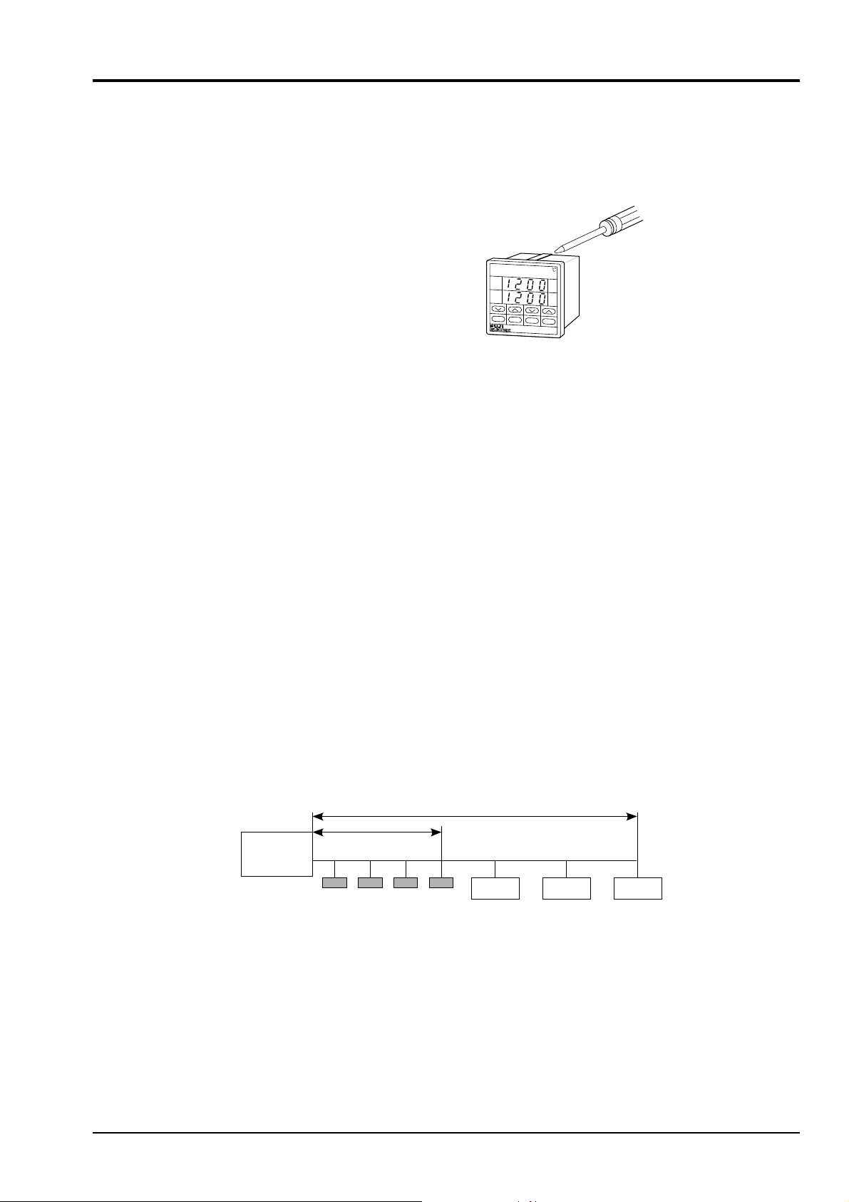
16. INSTALLATION AND WIRING
PV
SV
FLT
P
VSV
S
EL
D
ATA
E
N
T
C1
H
L
HB
C2
R
A
M
■ Installation
• This controller complies with DIN43700 standards.
• Recommended thickness of the panel is 1 to 8 mm.
•When mounting, attach the mounting brackets (two) on the top and bottom and tighten with a flat blade screwdriver.
(Tightening torque: About 147N • cm or less)
■ Environment of installation location
•Do not install in a place with corrosive gases (sulfuric gas, ammonia, etc.).
•Do not install in a place subject to vibration, impact, water or high temperature.
• Do not install near a device generating high frequency noise.
• Do not install in a place where ambient temperature changes suddenly or radiation from furnace is present. Ambient temperature of installation location should be -10 to 50°C.
■ Wiring
• For thermocouple input, connect the specified compensating lead wire.
• For resistance bulb input, use a lead wire having a small resistance.
• To prevent the effect of inductive noise, input signal cable and controller cable connected to power supply should
be wired away from the power line and the load line.
• For the controller with heater burnout alarm, the heater and controller power sources should be connected to the
same power line.
• Input signal cable should be wired away from output signal cable and protected with a shield.
■ T-link transmission cable
• Be sure to use the following cable (Max. 500m).
Twisted pair cable (equivalent to the twisted pair cable manufactured by The Furukawa Electric Co., Ltd. Type:
CPEV-SB, φ0.9 × 1 pair)
500m
MICREX-F
Processor
PYH
1km
Capsul Capsul Capsul
■ Use of controller output for sequence circuit
• When power is ON, it takes a few seconds until the internal relay starts operating. To use the controller contact
output for the sequence circuit, a delay relay should also be used.
When external wiring generates much noise, a protective device such as a surge killer should be used.
■ In case there is much noise from external wiring, the following countermeasure is required.
When a contactor is connected as a load of digital output such as a relay contact output or alarm output, use a surge
absorbor on the coil side of the contactor.
Fuji’s obsorber: Z-rap (200V AC, ENB461D-14A)
INP-TN3PYH-E 37
Page 44

16. INSTALLATION AND WIRING
■ Wiring of load circuit
•When the controller is used frequently such as for proportional action and a load which just satisfies the capacity of
the output relay is connected, the life of the controller is shortened. In such a case, it is recommended to use SSR or
SSC output type.
Solenoid switch: Proportional cycle, 30 s or more
SSC, SSR: Proportional cycle, one sec. or more
• Relay contact output and alarm output are insulated from input, but other outputs are not insulated and an insulating
transformer should be used as necessary.
■ Terminals
•Rod type cramp terminals are used. Select wiring materials from the following.
Solid wire : 2.5 mm2 max.
Twisted wire: 1.5 mm2 max.
AWG: 14
8mm
lead wire
• Use twisted wire of 0.75mm2 for tightening 2 leads together.
• The length of lead wire without sheath is about 8 mm.
The end of lead wire should be properly treated.
• Do not allow excessive force when tightening terminal screws.
•Use of rod terminals shown below is recommended.
Maker: Phoenix Contact Co.
φ C
A
Name of product: Ferrule without insulating collar
Kinds
For 0.5 sq
For 0.75 sq
For 1.0 sq
For 1.5 sq
Part No.
3200218
3200221
32002476
3200263
minus driver
A (mm)
6
6
6
7
φ C (mm)
1.0
1.4
1.6
1.8
38 INP-TN3PYH-E
Page 45

17. CODE SYMBOLS
1234 5678 910111213
PYH –
5
7
9
A
B
C
D
E
F
G
3
2
2
1
2
3
4
0
1
2
3
0
1
Y
R
T
Y
A
B
C
A
B
C
Y
A
B
C
Description
Front panel size
48 × 96mm *1
72 × 72mm
96 × 96mm
Control functions
Fixed value control type
Fixed value control type (SV select type)
Inverter control type (SV select type) ··· PYH9 only
Position feedback control type
Position feedback control type (SV select type)
Dual control type
Dual control type (SV select type)
Control output 1
Relay contact output
SSR/SSC drive output
4 to 20mA DC output
Pulse output (position feedback control type only)
Control output 2 (dual control type only)
None
Relay contact output
SSR/SSC drive output
4 to 20mA DC output
Additional specification 1
None
With heater burnout alarm (control output; relay contact output only)
Transmission function
None
With RS-485
With T-link for MICREX-F (PYH9 only)
Additional specification 2
None
With external set value input
With external transfer output
A + B
Input specification type
mV / Thermocouple / resistance bulb multi-input type
4 to 20mA DC / 1 to 5V DC multi-input type
4 to 20mA DC (with transmitter power source) input type
(Unavailable for 10th digit T)
Digital output
None
DO1
DO1 + DO2
DO1 + DO2 + DO3
PYH9 only
}
1
2
*1:
PYH5
PYH5 3
INP-TN3PYH-E 39
Case is not compatible.
}
Replace together with case.
 Loading...