

Page 1
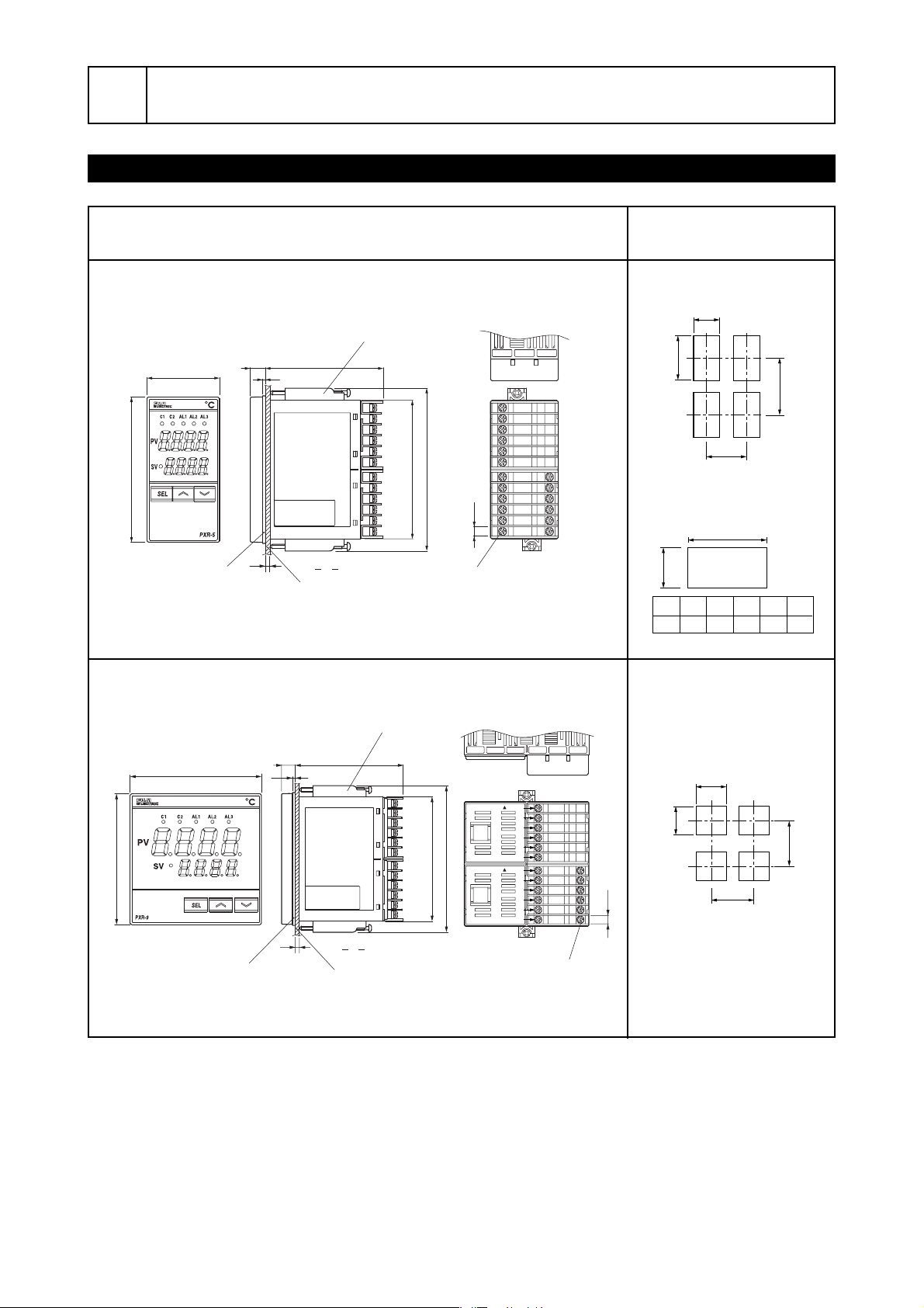
1 Installation/mounting
Mounting n units
Horizontal close-fit mounting
(Water proof is impossible in case
of horizontal close-fit mounting)
50Min
45
92
+0.6
0
116Min
+0.8
0
a
+0.8
0
+0.8
0
Q’ty
2933
141418952376285
92
a
Outline and Panel Cutout Dimensions
PXR5
96
48
Packing for
water proof
Outline dimensions (unit:mm)
Mounting fixture
(fastening torque : 0.15N·m)
2
t
7810
1 ≤ t ≤ 8
Panel
91.5
115.5 Max
Terminal screw M3
6.2
Panel cutout dimensions
(unit:mm)
1-12
25-36
13-24
1
2
3
4
5
6
7
8
9
10
11
12
31
32
33
34
35
36
PXR9
96
Note ) Panel cutout dimensions should also satisfy the above values after the panel is coated.
Cautions on close-fit mounting
Cautions on wiring
Mounting fixture
(fastening torque : 0.15N·m)
1-12
13-2437-48 61-7249-60
96
Packing for
water proof
79.510
25-36
2
TOP
1
2
3
4
5
91.5
115.5 Max
t
1 ≤ t ≤ 8
Panel
6
TOP
7
8
9
10
11
12
Terminal screw M3
31
32
33
34
6.2
35
36
Mounting n units
92
+0.8
0
92
• With the power supply of 200 V AC or more, a maximum ambient temperature is 45˚C .
(It is recommended to use a fan for cooling.)
• When there is another instrument (larger than 70mm) or a wall on the right side of this
controller, be sure to install the controller keeping a space of more than 30mm.
• Wiring should be started from the left side terminal (No. 1 to No. 12).
• Use crimped terminals matched to the screw size. Tightening torque should be 0.8 N·m.
• Do not connect anything to terminals not used.
– 10 –
+0.8
0
100 Min
116 Min
Page 2
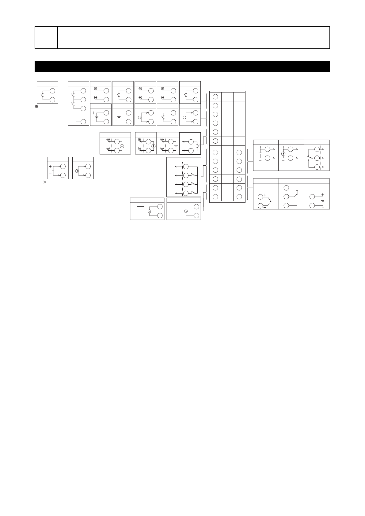
2Wiring
Terminal Connection Diagram (100 to 240
Digital input
In the case of 1
digital input
point (the 11th,
12th, or 13th
digit of the code
symbol is “S00”),
connect the digital input
terminal between
terminals q and w.
Remote SV input
In the case of 2 digital input
points + heater break alarm,
or 2 digital input points + remote
SV specifications, connect the CT
input and remote input terminals
between terminals t and y.
Digital input
1
2
N.C.
5
6
1
DI1
2
DI2
3
4
CT input
RS485 com.
Remote SV input
Re-transmission output
5
6
Digital input
1
2
Remote SV input
3
4
Re-transmission output
5
6
Power
supply
RS485 com.
1
2
CT input
3
4
Control output 2
Current output
24V AC/DC
+
−
50/60Hz
RS485 com.
1
2
Digital input
3
4
SSR/SSC drive output
5
6
11
12
Digital input
1
2
CT input
3
4
Relay output
5
6
Alarm output
COM
7
AL1
8
AL2
9
AL3
10
100 to 240V AC
50/60Hz
(Note 1)
1
2
3
4
5
6
11
12
Note 1 : Check the power supply voltage before installation.
Note 2 : Connect the I/V unit (250Ω resistor) (accessory) between the terminal #5 and #6
in case of current input.
AC, 24V AC/24V DC
1
2
3
4
5
6
7
8
9
10
11
12
31
32
33
34
35
36
Control output 1
SSR/SSC drive output
Measured value inut
Thermocouple
35
36
Current output
31
32
Resistance bulb
)
Relay output
31
32
A
34
B
35
B
36
31
32
33
Current/voltage
35
36
(Note 2)
– 11 –
 Loading...