

Page 1
– 10 –
1 Installation/mounting
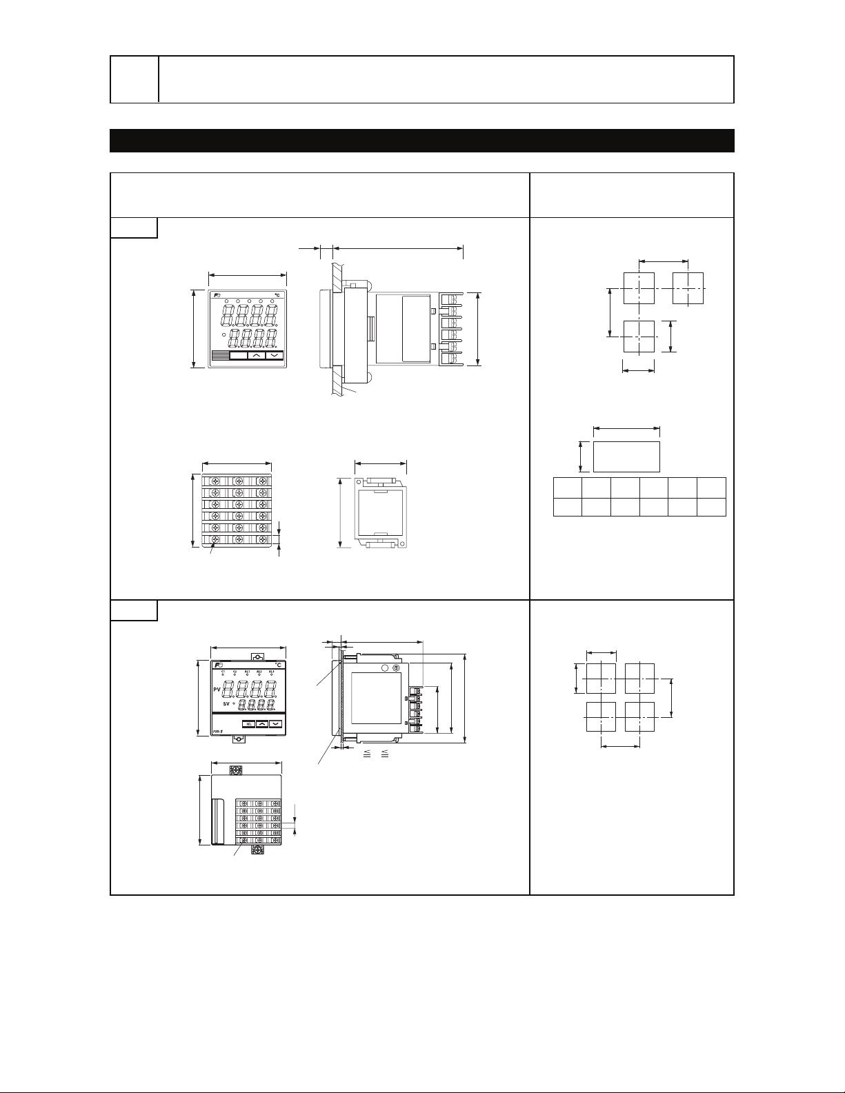
Outline and Panel Cutout Dimensions
63 or more
73 or more
+0.5
a
-
0
Number
of units
2 3 4 5 6
a 93 141 189 237 285
45
+0.5
0
45
+0.5
0
45
+0.5
0
For side by side installation,
see the Note1.
No. 000001T
PXR4TAA1-1YM00-D
MFD 2000-04
AL2AL1C1 C2 AL3
SEL
PXR-4
SV
PV
48
44.8
44.8
79.88
48
Mounting bracket
Panel
Panel thickness 1 to 8mm
48
44.8
57
6.2
Terminal screw M3×6
13
16
17
18
14
15
7
8
10
11
12
9
1
2
4
5
6
3
Outline dimensions (unit:mm)
Panel cutout dimensions
(unit:mm)
6.2
72
67
67
72
t
2
8.2
79.7
1 t 8
44.8
67
80.8
Panel
Packing
Terminal screw M3×6
92MIN.
0
+0.7
82MIN.
68
0
+0.7
68
PXR4
PXR7
Page 2
– 11 –
30 min.
70 or more
Note) Panel coating procedure must be taken into account, for the panel cutout dimension should still
conform with the dimensions listed in the left hand column.
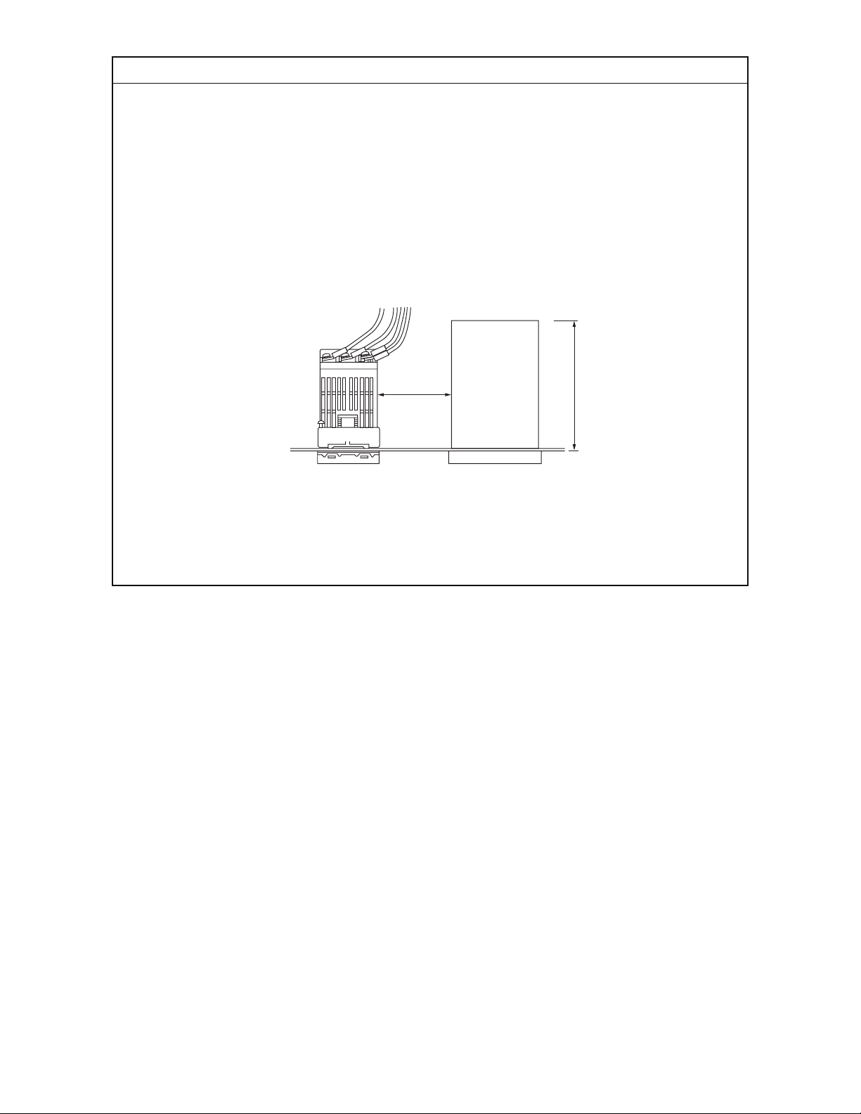
Caution on side-by-side installation:
• Maximum ambient temperature is at 45 ˚C when the power supply is at 200VAC or more. When
the PXR4 controller is tightly fixed in vertical and upright direction, the use of 100V AC power
supply is recommended .
(Installation of fan is recommended as a heat release measure)
• Make sure the controller is installed more than 30mm away, when there is an instrument of
more than 70mm depth or a wall on the right side of the controller.
• Side-by-side installation may sacrifice the controller’s waterproof property.
Caution on wiring:
• Terminals at the left hand side (from No.1 to 6) should be used first.
• Crimp terminals with matching screw size should be used. Tightening torque value should be
approx. 0.8N · m.
• Do not connect anything to the terminals that are not used. (Do not use as relay terminal)
Remarks
Page 3

– 12 –
2 Wiring
u
i
o
!0
!1
!2
Relay output
CT input
!1
!2
!1
!2
Control output2
SSR/SSC drive output
Current output
+
-
Digtal input
CT input
CT input
RS485 com.
+
-
Digtal input
RS485 com.
+
-
Remote SV input
RS485 com.
+
-
Remote SV input
Digtal input
u
i
Re-transmission output
Re-transmission output
+
-
u
i
Digtal input
Remote SV input
+
-
+
-
u
i
u
i
u
i
u
i
u
i
o
!0
o
!0
!1
!2
!1
!2
o
!0
o
!0
o
!0
o
N.C.
DI1
DI2
Digtal input
!0
+
-
!1
!2
+
-
!1
!2
· Common
· Alarm output1 (AL1)
· Alarm output2 (AL2)
· Heater break
Alarm output3 (AL3)
50/60Hz
Control output1
Alarm output
Power supply
(Note2)
(
Note1
)
Relay output
Thermocouple
Resistance bulb Current/voltage
Current output
uq !3
iw !4
oe !5
!3
!4
!3
!4
!3
!4
!5
+
A
B
B
-
+
-
+
-
+
-
!0r
q
w
e
r
!6
!1t !7
!2y
t
y
!8
!6
!7
!8
!7
!8
!7
!8
100-240V AC
SSR/SSC drive output
Measured value input
Note 1 : Check the power supply voltage before installation.
Note 2 : Connect the I/V unit (250Ω resistor) (accessory)
between the terminal !7 and !8 in case of
current input.
In the case of 1 digital input
point (the 11th, 12th, or 13th
digit of the code symbol is “S00”),
connect the digital input terminal
between terminals u and i.
In the case of 2 digital input points + heater break alarm,
or 2 digital input points + remote SV specifications, connect the CT
input and remote input terminals between terminals !1 and !2.
t
y
24V AC/DC
+
-
Terminal Connection Diagram (100 to 240
AC, 24V AC/24V DC
)
 Loading...