

Page 1

USER’S MANUAL
Hardware
series
FEH526c
Page 2

Preface
Thank you for purchasing Fuji Electric Programmable Controller MICREX-SX SPF Series.
This User’s Manual describes the hardware specications of the SPF series.
Read this manual carefully to ensure correct operation and also read the corresponding user’s manuals listed below.
Title Manual No. Contents
User’s Manual Instructions (Standard),
MICREX-SX series SPF
User’s Manual Instructions (Standard),
MICREX-SX series SPH
User’s Manual Instructions (Expert),
MICREX-SX series SPF
User’s Manual Instructions (Expert),
MICREX-SX series SPH
User’s Manual Analog Unit,
MICREX-SX series SPF
User’s Manual Built-in High-Speed Counter,
MICREX-SX series SPF
User’s Manual
General Purpose Communication,
MICREX-SX series SPF
User’s Manual Pulse Output Instructions,
MICREX-SX series SPF
User’s Manual SX-Programmer Standard
<Reference>, MICREX-SX series
User’s Manual SX-Programmer Expert
(D300win) <Reference>, MICREX-SX series
FEH524
FEH588
FEH525
FEH200
FEH527
FEH534
FEH528
FEH529
FEH598
FEH257
Describes the memory specications and instructions specic to
the SPF series (Standard).
Describes the memory, language and system denitions of the
MICREX-SX series SPH (Standard).
Describes the memory specications and instructions specic to
the SPF series (Expert).
Describes the memory, language and system denitions of the
MICREX-SX series SPH (Expert).
Describes the specications and operations of analog input/output
units of the MICREX-SX series SPF.
Describes the specications and operations of the high-speed
counter built in the main unit of the MICREX-SX series SPF.
Describes the specications of general purpose communication
(RS-232C/RS485) units/boards of the MICREX-SX series SPF
and how to create applications.
Describes the specications and operations of the high-speed
pulse output and high-speed positioning functions built in the main
unit of the MICREX-SX series SPF.
Describes the functions and the operations of SX-Programmer
Standard V3.
Describes the functions and the operations of SX-Programmer
Expert (D300win) V3.
* In addition to the above manuals, the following Fuji Electric Co.,Ltd.site offers various manuals and technical documents
associated with MICREX-SX series.
URL http://www.fujielectric.com
Notes
1. This manual may not be reproduced in whole or part in any form without prior written approval by the manufacturer.
2. The contents of this manual (including specifications) are subject to change without prior notice.
3. If you find any ambiguous or incorrect descriptions in this manual, please write them down (along with the manual No.
shown on the cover) and contact FUJI.
Page 3

Safety Precautions
: Incorrect handling of the device may result in minor injury or physical damage.
Be sure to read the "Safety Precautions" thoroughly before using the module.
Here, the safety precautions items are classied into "Warning" and "Caution".
Warning
: Incorrect handling of the device may result in death or serious injury.
Caution
Even some items indicated by "Caution" may result in a serious accident.
Both safety instruction categories provide important information. Be sure to strictly observe these instructions.
Warning
Neve touch any part of charged circuits as terminals and exposed metal portion while the power is turned ON.
It may result in an electric shock to the operator.
Turn OFF the power before mounting, dismounting, wiring, maintaining or checking, otherwise, electric shock, erratic
operation or troubles might occur.
Place the emergency stop circuit, interlock circuit or the like for safety outside the PLC. A failure of the PLC might break
or cause problems to the machine.
When using an expansion right side unit, be sure to mount a healthy unit to stop the SPF system with a fatal fault if the
expansion right side unit is dropped. Unless a healthy unit is mounted, a dropout of the expansion right side unit is not
detected and the SPF system continues operation in the state where the expansion right side unit is dropped.
Page 4

Safety Precautions
Caution
Do not use one found damaged or deformed when unpacked, otherwise, fire, failure or erratic operation might be caused.
Do not shock the product by dropping or tipping it over, otherwise, it might be damaged or troubled.
Follow the directions of the instruction manual and user’s manual when mounting the product.
If mounting is improper, the product might drop or develop problems or erratic operations.
Use the rated voltage and current mentioned in the instruction manual and user’s manual. Use beyond the rated values
might cause fire, erratic operation or failure.
Operate (keep) in the environment specified in the instruction manual and user’s manual. High temperature, high humidity,
condensation, dust, corrosive gases, oil, organic solvents, excessive vibration or shock, might cause electric shock, fire,
erratic operation or failure.
Select a wire size to suit the applied voltage and carrying current. Tighten the wire terminals to the specified torque.
Inappropriate wiring or tightening might cause fire, malfunction, failure or might cause the product to drop from its
mounting.
Contaminants, wiring chips, iron powder or other foreign matter must not enter the device when installing it, otherwise, fire,
accident, erratic operation or failure might occur.
Remove the dust-cover seals of modules after wiring, otherwise, fire, accident, erratic operation or failure might occur.
Connect the ground terminal to the ground, otherwise, electric shock or erratic operation might occur.
Periodically make sure the terminal screws and mounting screws are securely tightened.
Operation at a loosened status might cause fire or erratic operation.
Put the furnished connector covers on unused connectors, otherwise, erratic operation or failure might occur.
Sufficiently make sure of safety before program change, forced output, starting, stopping or anything else during a run.
Wrong operation might break or cause problems to the machine
Engage the loader connector in a correct orientation, otherwise, an erratic operation might occur.
Before touching the PLC, discharge any static electricity that may have been collected on your body. To discharge it, touch
a grounded metallic object. Static electricity might cause erratic operation or failure.
Be sure to install the electrical wiring correctly and securely, observing the directions of the instruction manual and user’s
manual. Wrong or loose wiring might cause fire, accident or failure.
When disengaging the plug from the outlet, do not pull the cord, otherwiase, break of cable might cause fire or failure.
Do not attempt to change system configurations (such as installing or removing expansion block) while the power is ON,
otherwise, failure or erratic operation might occur.
Do not attempt to repair the module by yourself, but contact your Fuji Electric agent, otherwise, fire, accident or failure
might occur.
To clean the module, turn power off and wipe the module with a cloth moistened with warm water. Do not use thinner or
other organic solvents, as the module surface might become deformed or discolored.
Do not remodel or disassemble the product, otherwise, failure might occur.
Follow the regulations of industrial wastes when the device is to be discarded.
The products covered in this user’s manual have not been designed or manufactured for use in equipment or systems
which, in the event of failure, can lead to loss of human life.
Do not use the products covered in this user’s manual for special applications, such as power plant, radiation facilities,
railroad, space/flight equipments, lifeline facilities, or medical equipments, where a great effect on human life, body,
society, major property or rights may be anticipated and high degree of safety is required.
Be sure to provide protective measures when using the products covered in this manual in equipment which, in the event
of failure, can lead to loss of human life or other grade results.
External power supply (such as 24 V DC power supply) which is connected to DC I/O should be strongly isolated from AC
power supply, otherwise, accident or failure might occur. (Use of EN60950 conforming power supply is recommended.)
Do not use the peoducts covered in this user’s manual in a residential environment.
Page 5

Revision
* The manual No. is printed at the bottom right of the cover of this manual.
Printed on * Manual No. Revision contents
Jan. 2017 FEH526 First edition (preliminary edition)
Jan. 2017 FEH526a Ofcial edition
June 2017 FEH526b • The specications of new models were added.
(NA0E08T-3, NA0E08T-0, NA0E16R-0, NA0AX02-TC, NA0AX16-TC, NA0AX06-PT,
NA3AY02-MR, NA3AW03-MR, NA0LA-RS3)
• The structure of the manual were altered.
Oct. 2017 FEH526c • The specications of new models were added.
(NA3LA-ET1, NA0LA-ET1, NA0FA-LC1)
• The description of a memory pack was added.
• The contents were revised.
Page 6

Contents
Preface
Safety Precautions
Revision
Contents
Section 1 Overview
1-1 Features .............................................................................................................................................1-1
1-1-1 Overview of system conguration .................................................................................................................1-1
1-1-2 Function list ...................................................................................................................................................1-2
1-2 Type Code .......................................................................................................................................... 1-3
1-3 Product Type List ................................................................................................................................1-5
1-4 Supported Versions ............................................................................................................................ 1-7
1-4-1 Program loader version .................................................................................................................................1-7
1-4-2 Main unit version ...........................................................................................................................................1-7
Section 2 System Conguration
2-1 System Conguration Specications ..................................................................................................2-1
2-1-1 Expansion specications ...............................................................................................................................2-2
2-1-2 Calculation of current consumption ...............................................................................................................2-3
2-2 System denition ................................................................................................................................2-7
2-3 I/O address assignment .....................................................................................................................2-8
2-3-1 Rules for assigning I/O addresses ................................................................................................................2-8
2-3-2 Example of address assignment ...................................................................................................................2-9
Section 3 Specications
3-1 General Specications .......................................................................................................................3-1
3-2 Main Unit Specications .....................................................................................................................3-2
3-2-1 Performance specications ...........................................................................................................................3-2
3-2-2 Memory backup and internal battery specications ......................................................................................3-3
3-2-3 Calendar specications .................................................................................................................................3-3
3-3 Power supply specications ...............................................................................................................3-4
3-3-1 AC power supply type ...................................................................................................................................3-4
3-3-2 DC power supply type ...................................................................................................................................3-4
3-4 Input specications .............................................................................................................................3-5
3-4-1 DC input specications..................................................................................................................................3-5
3-5 Output Specications .........................................................................................................................3-7
3-5-1 Transistor output specications .....................................................................................................................3-7
3-5-2 Relay output specications ...........................................................................................................................3-10
3-5-3 Output device protection and noise suppression in DO circuit......................................................................3-12
3-6 Analog Unit/Board Specications .......................................................................................................3-15
3-6-1 Analog input unit (NA0AX06-MR) .................................................................................................................3-15
3-6-2 Analog output unit (NA0AY02-MR) ...............................................................................................................3-16
3-6-3 Analog input/output unit (NA0AW06-MR) .....................................................................................................3-17
3-6-4 Analog output board (NA3AY02-MR) ............................................................................................................3-19
3-6-5 Analog input/output board (NA3AW03-MR) ..................................................................................................3-20
3-6-6 Thermocouple input unit (NA0AX02-TC/NA0AX06-TC/NA0AX16-TC) .........................................................3-21
3-6-7 Resistance thermometer element input unit (NA0AX06-PT).........................................................................3-24
3-7 Communication Unit/Board Specications .........................................................................................3-25
3-7-1 RS-232C/RS-485 general purpose communication board (NA3LA-RS1) .....................................................3-25
3-7-2 RS-232C general purpose communication unit (NA0LA-RS3) .....................................................................3-26
Page 7

Contents
3-7-3 RS-485 general purpose communication unit (NA0LA-RS5) ........................................................................3-27
3-7-4 Ethernet communication board (NA3LA-ET1) / Ethernet communication unit (NA0LA-ET1) .......................3-28
3-8 Function Unit Specications ...............................................................................................................3-29
3-8-1 Load cell unit (NA0F-LC1).............................................................................................................................3-29
3-8-2 High-precision load cell unit (NA0FA-LC1)....................................................................................................3-31
3-9 Temperature derating of main unit .....................................................................................................3-32
3-10 Terminal Arrangement ......................................................................................................................3-34
3-10-1 Main unit .....................................................................................................................................................3-34
3-10-2 Expansion unit ............................................................................................................................................3-37
3-11 Names and Functions ......................................................................................................................3-39
3-11-1 Main unit .....................................................................................................................................................3-39
3-11-2 Expansion unit ............................................................................................................................................3-42
3-12 Dimensions ......................................................................................................................................3-44
3-12-1 Main unit .....................................................................................................................................................3-44
3-12-2 Expansion unit ............................................................................................................................................3-46
3-13 Mass ................................................................................................................................................. 3-49
Section 4 Installation and Wiring
4-1 Installation Precautions ......................................................................................................................4-1
4-1-1 Installation Environment ................................................................................................................................4-1
4-1-2 Before installation..........................................................................................................................................4-2
4-1-3 Control panel mounting (protection against noise)........................................................................................4-3
4-1-4 Environmental condition for mounting PLC on panel ....................................................................................4-5
4-1-5 Mounting methods.........................................................................................................................................4-6
4-2 Wiring .................................................................................................................................................4-11
4-2-1 Wiring and cables..........................................................................................................................................4-12
4-2-2 Wiring to power-supply, I/O and ground terminals ........................................................................................4-13
Section 5 Maintenance and Inspection
5-1 General Inspection Items ...................................................................................................................5-1
5-1-1 Inspection frequency .....................................................................................................................................5-1
5-1-2 Cautions on using the product ......................................................................................................................5-1
5-1-3 Inspection items ............................................................................................................................................5-2
5-2 Actions to be Taken When Battery Voltage Drop is Detected ............................................................5-3
5-3 Maintenance Services ........................................................................................................................5-4
5-3-1 Ordering notes ..............................................................................................................................................5-4
5-3-2 Free-of-charge warranty period and scope of warranty ................................................................................5-4
5-3-3 Service costs .................................................................................................................................................5-4
Appendix 1 Installing USB Driver ..............................................................................................App.1-1
Appendix 2 Automatic Update of System Software .................................................................App.2-1
Page 8

Section 1 Overview
1-1 Features .................................................................................................... 1-1
1-1-1 Overview of system conguration ...............................................................1-1
1-1-2 Function list ................................................................................................1-2
1-2 Type Code ................................................................................................. 1-3
(1) Main unit ..................................................................................................... 1-3
(2) DIO expansion unit (expansion right side unit) ........................................... 1-3
(3) Analog unit (expansion right side unit) ....................................................... 1-3
(4) Function unit (expansion right side unit) ..................................................... 1-4
(5) Analog board .............................................................................................. 1-4
(6) Communication board ................................................................................ 1-4
(7) Communication unit (expansion left side unit) ............................................ 1-4
(8) Function unit (expansion left side unit) ....................................................... 1-4
(9) Expansion power supply unit ...................................................................... 1-4
1-3 Product Type List ..................................................................................... 1-5
1-4 Supported Versions ................................................................................. 1-7
1-4-1 Program loader version .............................................................................. 1-7
1-4-2 Main unit version ........................................................................................1-7
Page 9
Section 1 Overview
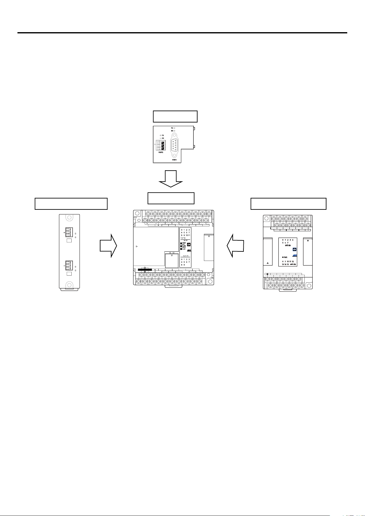
• Expansion power supply unit
1-1 Features
1-1-1 Overview of system conguration
The SPF series units are small controllers equipped with excellent functions comparable to medium-sized controllers and
maximum ve communication ports.
Various types of expansion units are available. One unit can be connected on the front of or on the left side of the main unit and
six units on the right side. In addition, interface options such as RS-232C, RS-485, and Ethernet enable you to use peripheral
communication devices.
PORT4 (RS485)
+
G
TNN
PORT3 (RS485)
+
G
T
NA0LA-RS5
Front board
* Mounted on the front of the main unit.
• Communication board
• Analog board
Main unit
Expansion right side unitExpansion left side unit
X12X10
24V OUT
S/S
AC100~240V
C0
X0
X1 X3
PORT0
Y2
Y0
C2
max.
400mA
TX
RX
TX
RX
IN
X8
X4X2
X6
X5 X7
RXTX
Y4
Y3
C4 C6
X11 X13
X9
Y5
Y6Y1
SINK
Y8
SRCE
Y7
Y9
Y1Y2C2 C4C0
Y0
Y10Y8 Y11 Y12 Y14
Y9C8 C10 C12 Y13 Y15
Y3 Y4 Y6
Y5 Y7
• Communication unit
• High-accuracy load cell unit
• Advance main unit
(High-speed counter, positioning function)
• Basic main unit
(High-speed counter)
• Digital input/output unit
• Analog unit
• Temperature measuring unit
• Load cell unit
1-1
Page 10

Section 1 Overview
1-1-2 Function list
Item Specication
External interrupt input function Max. 16 points (Rising edge / falling edge / both edges)
Pulse catch function Max. 36 points (Rising edge / falling edge)
No. of channels Max. 8 channels (single phase)
High-speed counter
0.1ms high-speed timer When using high-speed counter in high-speed timer mode
High-speed pulse
output
&
High-speed
positioning
Communication port
Diagnostic function
Security function Password (Set by the support tool)
Calendar function
Count frequency
Count mode U/D, U/D×2, P/R, P/R×2, A/B, A/B×2, A/B×3, A/B×4 (Note 1)
No. of axes Max. 4 axes
Output frequency Max. 200kHz
Output pulse mode U/D, P/R, A/B, PLS, PWM (Note 1) (Note 2)
Pulse output instruction By SPF-specic instruction
PORT0 (RS-232C) Loader port built in main unit
PORT1, PORT2
(Communication board)
PORT3, PORT4
(Communication unit)
Max. 200kHz (Advance main unit)
Max. 100kHz (Basic main unit)
Communication mode:
Loader communication, general-purpose communication, simplied CPU link
communication (only one port among them),
Modbus RTU master communication
Communication speed:
1200/2400/4800/9600/19200/38400/57600/115200 bps
Self-diagnosis (memory check, ROM sum check), System conguration
supervising
Available up to 31 Dec. 2069 23:59:59
Precision: ±20 sec/day (at 25°C)
Program memory,
system denition
Backup
(Note 2)
User ROM function
Notes:
1) U/D: Up/Down pulse mode, P/R: Pulse / Direction signal mode, A/B: A/B phase mode, x2: 2 multiplication, x3: 3
multiplication, x4: 4 multiplication
2) PLS: Single pulse output mode, PWM: PWM output mode
3) The backup time is 10 years or more (ambient temperature: 55°C)
4) Notes on rewriting programs
When rewriting the program in the main unit from the loader while the PLC is running, the built-in RAM is changed,
however, the built-in ash memory is unchanged. As a result, the contents of the RAM does not match those of the ash
memory and the RUN/MEM LED blinks to prompt the user to transfer the contents of the RAM to the ash memory.
After rewriting the program, be sure to transfer the contents of the RAM to the ash memory. When the transfer is
completed normally, the RUN/MEM LED turns OFF.
<Method 1>
Perform transfer by using the loader.
<Method 2>
After rewriting the program, turn OFF the main unit and then ON again. When the power supply is turned ON, the contents
of the RAM is automatically transferred to the ash memory.
ZIP le Built-in ash memory
Data memory Built-in RAM: Built-in lithium primary battery
Calendar Calendar IC: Built-in lithium primary battery
Built-in RAM: Built-in primary lithium battery
Built-in ash memory (Note 4)
Programs, system denitions, and zipped les can be stored in the external
memory pack (NA8PMF-20).
1-2
Page 11

Section 1 Overview
Main unit
Ty
B: Basic
No. of I/O points
14: 14 points (Input 8 points / Output 6 points)
24: 24 points (Input 14 points / Output 10 points)
32: 32 points (Input 20 points / Output 12 points)
40: 40 points (Input 24 points / Output 16 points)
60: 60 points (Input 36 points / Output 24 points)
AC)
T: Transistor sink output
NA0P AT-31C24
DIO expansion uni
No. of I/O points
08: 8 points
16: 16 points
24: 24 points
3: Input is provided. (24V DC, Non-polarity)
T: Transistor sink output
NA0E 24 R-31
NA0A X06-MR
No. of channels
02: 2CH
06: 6CH
16: 16CH
: Resistance thermometer element input
A
1-2 Type Code
This subsection describes the rule of type codes.
(1) Main unit
Calendar
C: Calendar is provided.
pe
A: Advance
(2) DIO expansion unit (expansion right side unit)
t
Power supply specifications
1: AC power supply (100 to 240V
4: DC power supply (24V DC)
Input specifications
3: 24V DC (Non-polarity)
Output specifications
R: Relay output
Power supply specifications
1: AC power supply (100 to 240V AC)
4: DC power supply (24V DC)
None: No power supply is provided.
Input specifications
0: No input is provided.
Output specifications
X: No output is provided. (all points input)
R: Relay output
(3) Analog unit (expansion right side unit)
nalog unit
I/O type
X: Input
Y: Output
W: Input/output
MR: Multi-range
TC: Thermocouple input
PT
1-3
Page 12

Section 1 Overview
NA0F
Function unit LC1: Load cell unit
LC1-
NA0S
Expansion
power supply unit
2-
AC)
4: DC power supply (24V DC)
NA0LA
Communication
unit
RS3: RS-232C 2CH
ET1: Ethernet
RS5-
NA3LA
Communication
board
RS1: RS-232C 1CH, RS-485 1CH
ET1: Ethernet
RS1-
NA3A Y02-MR
No. of channels
02: 2CH
03: 3CH
MR: Multi-range
A
NA0FA
Function unit
LC1: High-precision load cell unit
LC1-
(4) Function unit (expansion right side unit)
(5) Analog board
nalog board
I/O type
Y: Output
W: Input/output
(6) Communication board
(7) Communication unit (expansion left side unit)
(8) Function unit (expansion left side unit)
(9) Expansion power supply unit
RS5: RS-485 2CH
Power supply specifications
2: AC power supply (100 to 240V
1-4
Page 13

Section 1 Overview
1-3 Product Type List
Product name Type Specication
NA0PB14R-34C
24V DC power supply, 24V DC digital input 8 points (High-speed: 100kHz, 2 points;
Medium-speed: 20kHz, 2 points; Medium-speed: 16.6kHz, 4 points;), Ry output 6 points
Advance main unit
(NA0PB***)
Basic main unit
(NA0PA***)
NA0PB24R-34C
NA0PB32R-34C
NA0PB60R-34C
NA0PA14T-34C
NA0PA24T-34C
NA0PA32T-34C
NA0PA40T-34C
NA0PA60T-34C
NA0PA24T-31C
24V DC power supply, 24V DC digital input 14 points (High-speed: 100kHz, 2 points;
Medium-speed: 20kHz, 6 points; Medium-speed: 16.6kHz, 6 points;), Ry output 10 points
24V DC power supply, 24V DC digital input 20 points (High-speed: 100kHz, 2 points;
Medium-speed: 20kHz, 6 points; Medium-speed: 16.6kHz, 8 points;), Ry output 12 points
24V DC power supply, 24V DC digital input 36 points (High-speed: 100kHz, 2 points;
Medium-speed: 20kHz, 6 points; Medium-speed: 16.6kHz, 8 points;), Ry output 24 points
24V DC power supply, 24V DC digital input 8 points (High-speed: 200kHz, 2 points;
Medium-speed: 20kHz, 2 points; Medium-speed: 16.6kHz, 4 points;), Tr sink output 6 points
(High-speed: 200kHz, 4 points; Medium-speed: 20kHz, 2 points), Detachable terminal block
24V DC power supply, 24V DC digital input 14 points (High-speed: 200kHz, 4 points;
Medium-speed: 20kHz, 4 points; Medium-speed: 16.6kHz, 6 points;), Tr sink output 10 points
(High-speed: 200kHz, 4 points; Medium-speed: 20kHz, 4 points), Detachable terminal block
24V DC power supply, 24V DC digital input 20 points (High-speed: 200kHz, 6 points;
Medium-speed: 20kHz, 2 points; Medium-speed: 16.6kHz, 8 points;), Tr sink output 12 points
(High-speed: 200kHz, 6 points; Medium-speed: 20kHz, 2 points), Detachable terminal block
24V DC power supply, 24V DC digital input 24 points (High-speed: 200kHz, 6 points;
Medium-speed: 20kHz, 2 points; Medium-speed: 16.6kHz, 8 points;), Tr sink output 16 points
(High-speed: 200kHz, 6 points; Medium-speed: 20kHz, 2 points), Detachable terminal block
24V DC power supply, 24V DC digital input 36 points (High-speed: 200kHz, 8 points;
Medium-speed: 16.6kHz, 8 points;), Tr sink output 24 points (High-speed: 200kHz, 8 points),
Detachable terminal block
100–240V AC power supply, 24V DC digital input 14 points (High-speed: 200kHz, 4 points;
Medium-speed: 20kHz, 4 points; Medium-speed: 16.6kHz, 6 points;), Tr sink output 10 points
(High-speed: 200kHz, 4 points; Medium-speed: 20kHz, 4 points),
Detachable terminal block
DIO expansion unit
(with power supply)
DIO expansion unit
(without power
supply)
NA0PA32T-31C
NA0PA40T-31C
NA0PA60T-31C
NA0E24R-34 24V DC power supply, 24V DC digital input 14 points, Ry output 10 points
NA0E24T-31 100–240V AC power supply, 24V DC digital input 14 points, Tr sink output 10 points
NA0E08R-3 24V DC digital input 4 points, Ry output 4 points
NA0E08T-3 24V DC digital input 4 points, Tr sink output 4 points
NA0E08X-3 24V DC digital input 8 points
NA0E08T-0 Tr sink output 8 points
NA0E16R-0 Ry output 16 points
NA0E16T-0 Tr sink output 16 points
100–240V AC power supply, 24V DC digital input 20 points (High-speed: 200kHz, 6 points;
Medium-speed: 20kHz, 2 points; Medium-speed: 16.6kHz, 8 points;), Tr sink output 12 points
(High-speed: 200kHz, 6 points; Medium-speed: 20kHz, 2 points),
Detachable terminal block
100–240V AC power supply, 24V DC digital input 24 points (High-speed: 200kHz, 6 points;
Medium-speed: 20kHz, 2 points; Medium-speed: 16.6kHz, 8 points;), Tr sink output 16 points
(High-speed: 200kHz, 6 points; Medium-speed: 20kHz, 2 points),
Detachable terminal block
100–240V AC power supply, 24V DC digital input 36 points (High-speed: 200kHz, 8 points;
Medium-speed: 16.6kHz, 8 points;), Tr sink output 24 points (High-speed: 200kHz, 8 points),
Detachable terminal block
1-5
Page 14

Section 1 Overview
Product name Type Specication
NA0AX06-MR
Analog input unit,
6 channels: 14-bit analog input (-10 to 10V, 0 to 10V, -20 to 20mA, 0 to 20mA)
AIO expansion unit
(without power supply)
Temperature measurement
unit
(without power supply)
Load cell unit NA0F-LC1 Load cell unit, 1 channel
AIO board
(Front board type)
Communication board
(Front board type)
Communication unit
(Expansion left side unit)
NA0AY02-MR
NA0AW06-MR
NA0AX02-TC Thermocouple input unit: 2 channels, resolution 0.1°C
NA0AX06-TC Thermocouple input unit: 16 channels, resolution 0.1°C
NA0AX16-TC Thermocouple input unit: 6 channels, resolution 0.1°C
NA0AX06-PT Resistance thermometer element input unit: 6 channels, resolution 0.1°C
NA3AY02-MR
NA3AW03-MR
NA3LA-RS1 Communication board, RS232C (Port 1) + RS-485 (Port 2)
NA3LA-ET1 Ethernet communication board, 1 channel
NA0LA-RS3 Communication unit, 2 ports RS-232C (Port 3 + Port 4)
NA0LA-RS5 Communication unit, 2 ports RS-485 (Port 3 + Port 4)
NA0LA-ET1 Ethernet communication unit, 1 channel
Analog output unit,
2 channels: 14-bit analog output (-10 to 10V, 0 to 10V, -20 to 20mA, 0 to 20mA)
Analog input/output unit
4 channels: 14-bit analog input (-10 to 10V, 0 to 10V, -20 to 20mA, 0 to 20mA) +
2 channels: 14-bit analog output (-10 to 10V, 0 to 10V, -20 to 20mA, 0 to 20mA)
Analog output board,
2 channels: 12-bit analog output (0 to 10V, 0 to 20mA)
Analog input/output board,
2 channels: 12-bit analog input (0 to 10V, 0 to 20mA) +
1 channel: 12-bit analog output (0 to 10V, 0 to 20mA)
High-precision load cell unit
(Expansion left side unit)
Expansion power supply unit
Healthy unit
(Terminating connector)
Memory pack NA8PMF-20 Memory for storing a project and data
Loader connecting cable NA0H-CUV RS-232C/USB conversion cable for loader connection port (Port 0), 1.8m (Note 1)
Personal computer loader
NA0FA-LC1 High-precision load cell unit, 1 channel
NA0S-2
NA0S-4
NA8P-HE Unit for detecting a dropout/fault of expansion right side units
NP4H-SEDBV3 SX-Programmer Expert (D300win)
NP4H-SWN SX-Programmer Standard
Input voltage: 100–240V AC, Output: internal 5V DC; internal 24V DC
Service power supply output: 24V DC; 21W
Input voltage: 24V DC, Output: internal 5V DC; internal 24V DC
Service power supply output: 24V DC, 14W
Notes:
1) You need to install the USB driver into the personal computer.
See “Appendix 1 Installing USB Driver.”
1-6
Page 15

Section 1 Overview
1-4 Supported Versions
1-4-1 Program loader version
1) Program loader versions that support the SPF series
• SX-Programmer Expert (D300win) : V3.6.11.* or later
• SX-Programmer Standard : V3.0.16.* or later
2) Program loader versions that support Ethernet communication board (Type: NA3LA-ET1), Ethernet communication unit
(Type: NA0LA-ET1) and High-precision load cell unit (Type: NA0FA-LC1)
• SX-Programmer Expert (D300win) : V3.6.12.* or later
• SX-Programmer Standard : V3.0.17.* or later
1-4-2 Main unit version
1) V03 or later software version of main units support analog boards that are connected on the front of them (Type: NA3AY02-MR,
NA3AW03-MR). Analog boards cannot be used with a main unit the software version of which is earlier than V03.
2) V04 or later software version of main units support Ethernet communication board (Type: NA3LA-ET1) and Ethernet
communication unit (Type: NA0LA-ET1). Ethernet communication board/unit cannot be used with a main unit the software
version of which is earlier than V04.
1-7
Page 16

Section 2 System Conguration
2-1 System Conguration Specications .................................................... 2-1
2-1-1 Expansion specications ............................................................................ 2-2
2-1-2 Calculation of current consumption ............................................................ 2-3
(1) Suppliable current ....................................................................................... 2-3
(2) Current consumption of main unit............................................................... 2-3
(3) Current consumption of expansion unit ...................................................... 2-4
2-2 System denition ..................................................................................... 2-7
2-3 I/O address assignment .......................................................................... 2-8
2-3-1 Rules for assigning I/O addresses..............................................................2-8
2-3-2 Example of address assignment ................................................................2-9
Page 17
Section 2 System Conguration
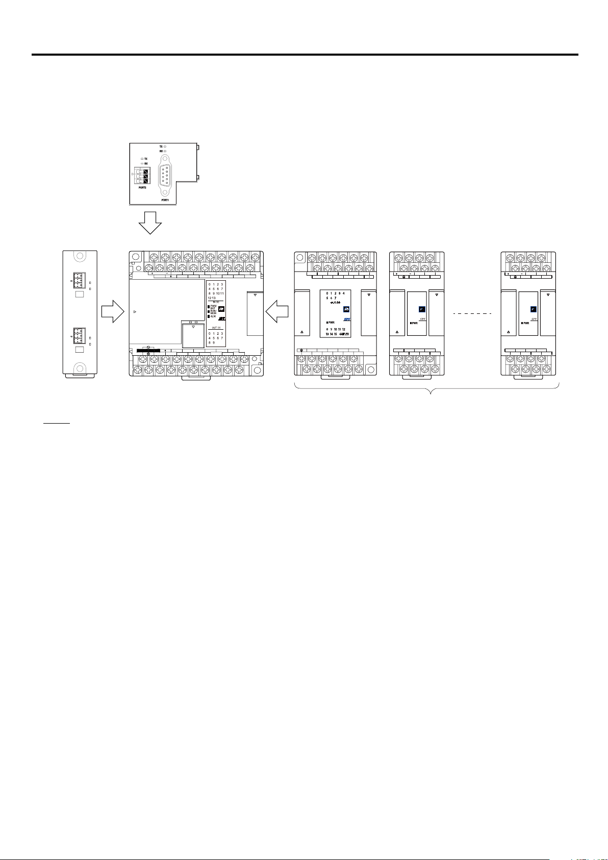
Expansion
left side unit
Front board
Max. 6 (Note 1)
2-1 System Conguration Specications
You can connect up to six expansion units on the right side, one expansion uint on the left side, and one front board on the front
of the SPF series main unit, respectively.
Max. 1
Expansion
right side unit
Y1Y2C2 C4C0
Y0
Y3 Y4 Y6
Y10Y8 Y11 Y12 Y14
Y9C8 C10 C12 Y13 Y15
Y5 Y7
O0+O1+
24V IN
AG O0-
I0+I1+ I2+I3+
I0-I1- I2-I3-
O1-
PORT4 (RS485)
+
G
TNN
PORT3 (RS485)
+
G
T
Main unit
X12X10
24V OUT
S/S
AC100~240V
C0
X0
X1 X3
PORT0
Y2
Y0
C2
max.
TX
RX
TX
RX
400mA
IN
X8
X4X2
X6
X5 X7
RXTX
Y4
Y3
C4 C6
X11 X13
X9
Y5
Y6Y1
SINK
Y8
SRCE
Y7
Y9
NA0LA-RS5
Max. 1
Notes:
1) The maximum number of connectable AIO units is 3.
An expansion power supply unit and healthy unit are excluded from the number of connectable units (Max. 6).
O0+O1+
24V IN
AG O0-
I0+I1+ I2+I3+
I0-I1- I2-I3-
O1-
2-1
Page 18

Section 2 System Conguration
2-1-1 Expansion specications
The table below shows the connectable expansion units.
Classication Product name Type Specication
Expansion right side
unit
Expansion left side
unit
Front board
DIO expansion unit
(with power supply)
DIO expansion unit
(without power supply)
AIO expansion unit
(without power supply)
Expansion power supply
unit
Healthy unit
(Terminating connector)
Communication unit
Function unit NA0FA-LC1 High-precision load cell unit, 1 channel (Note 2)
AIO board
Communication board
NA0E24R-34
NA0E24T-31 Input 14 points, Tr sink output 10 points, AC power supply
NA0E08R-3 Input 4 points, Ry output 4 points
NA0E08T-3
NA0E08X-3 Input 8 points
NA0E08T-0
NA0E16R-0
NA0E16T-0 Tr sink output 16 points
NA0AX06-MR Analog input 6 channels
NA0AY02-MR Analog output 2 channels
NA0AW06-MR Analog input 4 channels, Analog output 2 channels
NA0AX02-TC Thermocouple input 2 channels
NA0AX06-TC Thermocouple input 6 channels
NA0AX16-TC Thermocouple input 16 channels
NA0AX06-PT Resistance thermometer element input 6 channels
NA0F-LC1 Load cell unit, 1 channel
NA0S-2 Input 100 to 240V AC
NA0S-4 Input 24V DC
NA8P-HE
NA0LA-RS2 RS-232c: 2 ports (Note 2)
NA0LA-RS5 RS-485: 2 ports (Note 2)
NA0LA-ET1 Ethernet 1 channel (Note 2)
NA3AY02-MR Analog output 2 channels
NA3AW03-MR Analog input 2 channels, Analog output 1 channel
NA3LA-RS1 RS-232C: 1 port, RS-485: 1 port (Note 2)
NA3LA-ET1 Ethernet 1 channel (Note 2)
Input 14 points, Ry output 10 points, DC power supply
Input 4 points, Tr sink output 4 points
Tr sink output 8 points
Ry output 16 points
Unit for detecting a dropout/fault of expansion right side
units (Note 1)
Notes:
1) A healthy unit is used to detect a dropout of expansion right side units.
Be sure to mount a healthy unit to stop the SPF system with a fatal fault when an expansion right side unit is dropped.
Unless a healthy unit is mounted, a dropout of the expansion right side unit is not detected and the SPF system continues
operation in the state where the expansion right side unit is dropped.
Connect a healthy unit to the expansion connector (OUT) of the rightmost expansion right side unit after removing the
cover.
When mounting a healthy unit, register it in the system denition.
A healthy unit is excluded from the number of connectable expansion right side units (Max. 6).
2) A dropout of the communication unit/board and high-precision load cell unit is not detected.
2-2
Page 19

Section 2 System Conguration
2-1-2 Calculation of current consumption
(1) Suppliable current
Type Internal 5V DC Internal 24V DC Externally supplied 24V DC
Main unit NA0P
Expansion unit with
power supply
Expansion power supply NA0S-2 / NA0S-4 400mA 250mA 250mA
Notes:
1) When using an AC power supply type unit at a power supply voltage of 120V AC or less, the total of the internal 24V DC
and externally supplied 24V DC becomes 575mA.
oooo-oo
NA0E24T-31 948mA 350mA 337mA
NA0E24R-34 948mA Total 337mA
C 1000mA 400mA (Note 1) 400mA (Note 1)
(2) Current consumption of main unit
Type Internal 5V DC Internal 24V DC
NA0PB14R-34C 360mA 65mA 60mA
Advance main unit
Basic main unit
NA0PB24R-34C 435mA 85mA 105mA
NA0PB32R-34C 520mA 110mA 138mA
NA0PB60R-34C 555mA 200mA 210mA
NA0PA14T-34C 360mA 65mA 60mA
NA0PA24T-ooC 435mA 85mA 105mA
NA0PA32T-ooC 520mA 110mA 138mA
Externally supplied 24V DC
(Note 2)
NA0PA40T-ooC 530mA 125mA 156mA
NA0PA60T-ooC 555mA 200mA 210mA
2-3
Page 20

Section 2 System Conguration
(3) Current consumption of expansion unit
Type Internal 5V DC Internal 24V DC
NA0E08R-3 30mA 34mA 18mA
NA0E08T-3 30mA 34mA 18mA
DIO expansion unit
AIO expansion unit
Load cell unit NA0F-LC1 32mA – 48mA
AIO board
NA0E08X-3 30mA – 36mA
NA0E08T-0 29mA 68mA –
NA0E16R-0 40mA 136mA –
NA0E16T-0 40mA 136mA –
NA0AX06-MR 25mA – 53mA
NA0AY02-MR 33mA – 90mA
NA0AW06-MR 35mA – 103mA
NA0AX02-TC 30mA – 21mA
NA0AX06-TC 30mA – 29mA
NA0AX16-TC 30mA – 58mA
NA0AX06-PT 32mA – 16mA
NA3AY02-MR 223 – –
NA3AW03-MR 158 – –
Externally supplied 24V DC
(Note 2)
Communication board
Communication unit
High-precision load cell unit NA0FA-LC1 120mA – 48mA
Healthy unit NA8P-HE 10mA – –
Notes:
2) These values show consumed current when externally supplied 24V DC power supply is used for input/output power
supply. When not using externally supplied 24V DC power supply for input/output power supply, the current consumption
of externally supplied 24V DC becomes 0mA.
NA3LA-RS1 55mA – –
NA3LA-ET1 110mA – –
NA0LA-RS3 18mA – –
NA0LA-RS5 95mA – –
NA0LA-ET1 160mA – –
2-4
Page 21
Section 2 System Conguration
<Calculation example of current consumption>
Whether or not to use an expansion power supply is determined by the total current consumption of all the units. You need to
calculate the total current consumption and mount an expansion power supply unit if the current is insufcient.
Referring the tables on the previous page, calculate the current consumption.
Subtract the total current consumption of the main unit, additionally connected front board, expansion left side unit, and
expansion right side units from the current supplied from the main unit. When the result is minus, you need to mount an
expansion power supply. Thus mount an expansion power supply unit if the current is insufcient for the expansion units that are
connected on the right.
Expansion power supply units are excluded from the number of connectable expansion units.
● Main calculation formula
[Supplied current] - [Current consumption]
= [Current supplied from main unit] - [Current consumption of main unit]
- [Current consumption of front board]
- [Current consumption of expansion left side unit]
- [Total current consumption of expansion right side units]
>= 0
● Calculation formula for current consumption on the right of the expansion unit with power supply
(Expansion unit with power supply is referred to as “Exp_powunit” here.)
Exp_powunit receives the remaining current of the main unit on the left side and adds it to the current that Exp_powunit
supplies to supply expansion units connected on the right.
I_MainR + I_Exp_powunit - I_Exp >= 0
• I_MainR (Remaining current of main unit)
= [Current supplied from main unit] - [Current consumption of expansion left side unit]
- [Current consumption of expansion right side units]
- [Current consumption of front board]
• I_Exp_powunit (Current supplied from Exp_powunit)
• I_Exp (Total current consumption of expansion units that are connected on the right of Exp_powunit)
● Calculation formula when using an expansion power supply unit
Use the above calculation formula by replacing Exp_powunit with the expansion power supply unit.
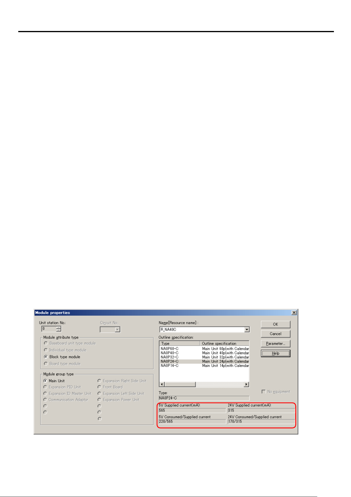
<Calculation of current consumption by using the loader function>
When registering units in the system denition by using the loader, you can check the total current consumption of the units and
the supplied current value.
(Since externally supplied 24V DC is not calculated by the loader, you need to calculate it.)
2-5
Page 22
Section 2 System Conguration
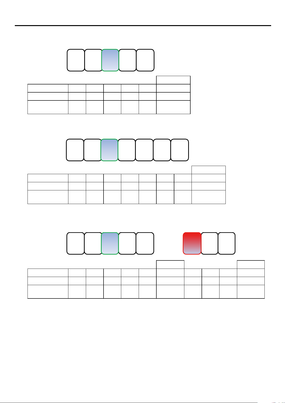
• Case 1
When the main unit can supply sufcient current
NA0L
A
-RS5
NA3L
A
-RS1
NA0P
A24T
-34C
NA0E
08R
-3
NA0E
16T
-0
Result
Internal 5V DC -95 -55 +565 -30 -40 +345 (OK)
Internal 24V DC +315 -34 -136 +145 (OK)
Externally supplied
24V DC
+295 -18 +277 (OK)
• Case 2
When the main unit cannot supply sufcient current
NA0L
A
-RS5
NA3L
A
-RS1
NA0P
A40T
-34C
NA0E
08R
-3
NA0E
16T
-0
NA0E
16T
-0
NA0A
X06
-MR
Result
Internal 5V DC -95 -55 +470 -30 -40 -40 -25 +185 (OK)
Internal 24V DC +275 -34 -136 -136 -31 (overload)
Externally supplied
24V DC
+244 -18 -53 +173 (OK)
• Case 3
When an expansion power supply unit is mounted in the case 2
NA0L
A
-RS5
NA3L
A
-RS1
NA0P
A40T
-34C
NA0E
08R
-3
NA0E
16T
-0
NA0S
-4
NA0E
16T
-0
NA0A
X06
-MR
Result Result
Internal 5V DC -95 -55 +470 -30 -40 +250 (OK) 400 -40 -25 +585 (OK)
Internal 24V DC +275 -34 -136 +105 (OK) 250 -136 +219 (OK)
Externally supplied
24V DC
+244 -18 +226 (OK) 250 -53 +423 (OK)
2-6
Page 23
Section 2 System Conguration
Type: NA0PA40T-31C
Expansion left side unit
Type: NA0LA-RS5
Type: NA0E16T-0
Expansion right side unit
Type: NA0AX06-MR
2-2 System denition
When using SPF series, you need to register the actual unit conguration in a project.
<Example of system conguration>
Front board
Type: NA3LA-RS1
PORT4 (RS485)
+
G
TNN
PORT3 (RS485)
+
G
T
NA0LA-RS5
X0 X2 X4 X6 X8 X10X12 X14X16 X18
24V OUT
.
x
a
m
S/S
400mA
TX
RX
TX
RX
IN AC100~240V
L N
X1 X3 X5 X7 X9 X11 X13X15 X17 X19
IN (X)
PWR/
BAT
RUN/
MEM
ALM
OUT (Y)
PORT0
Y1 Y2 Y4 Y5 Y6 Y8 Y10
C0 Y0 C2 Y3 C4 C6 Y7 C8 Y9 Y11
Main unit
X20X22
0
4
A
P
A
N
Y14Y12
C12Y13 Y15
X21X23
-
0
T
3
1
C
Y1Y2C2 C4C0
Y0
Y10Y8 Y11 Y12 Y14
Y9C8 C10 C12 Y13 Y15
Expansion right side unit
Y5 Y7
Y3 Y4 Y6
NA0E16T-0
O0+O1+
24V IN
AG O0-
NA0AW06-MR
I0+I1+ I2+I3+
I0-I1- I2-I3-
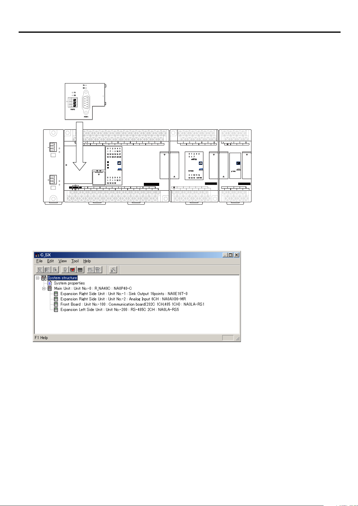
<System conguration denition tree window>
The system conguration denition tree for the above system conguration is shown below.
O1-
<Rules for dening system conguration>
• For system denition, the unit on the right of the main unit is registered just below the main unit.
As for the unit station Nos. of units, the main unit is always assigned “0” (zero), and numbers beginning with 1 (one) are
assigned to expansion right side units, in their connected order.
• The front board is connected on the front of the main unit and registered below the expansion right side unit in the conguration
denition tree. The unit station No. is xed to “100.”
• The expansion left side unit is connected to the left of the main unit and registered at the lowermost location in the conguration
denition tree. The unit station No. is xed to “200.”
2-7
Page 24
Section 2 System Conguration
{
Output:
<For Standard>
<For Expert (D300win)>
Y (bit), WY (word), DY (double-word)
2-3 I/O address assignment
2-3-1 Rules for assigning I/O addresses
In MICREX-SX series SPF, follow the rules below to assign I/O addresses.
Period
Prefix
Input:
{
Output:
Identifier
Input:
1) Unit No.
A number (1 to 6) is assigned to SPF expansion right side units, in their connected order. The number assigned to the main unit
is always “0” (zero). The front board is assigned “100” (xed) as an independent unit and the expansion left side unit with “200”
(xed).
<Example of unit No. assignment>
Unit No. Word No.
%IX (bit), %IW (word), %ID (double-word)
%QX (bit), %QW (word), %QD (double-word)
Period
Unit No. Word No.
X (bit), WX (word), DX (double-word)
Period
Bit address
(0 to 15)
Bit address
(0 to F)
Expansion
left side unit
Unit No. 200
2) Word No. and bit address
To each SPF unit, words starting from the word 0 (zero) are assigned for the number of words that the unit occupies. No same
word is assigned to both input and output. Therefore, for main unit and expansion units with both inputs and outputs, words are
assigned rst to inputs and then to outputs. All types of main units (regardless of the No. of I/O points provided) occupy eight
words of the I/O area (input: four words, output: four words).
Main unit
Unit No. 0
Front board
Unit No. 100
Expansion
right side unit
Unit No. 1
Expansion
right side unit
Unit No. 2
Expansion
right side unit
Unit No. 3
2-8
Page 25
Section 2 System Conguration
%QX0.4.0 to QX0.4.15 (Y0.40 to Y0.4F)
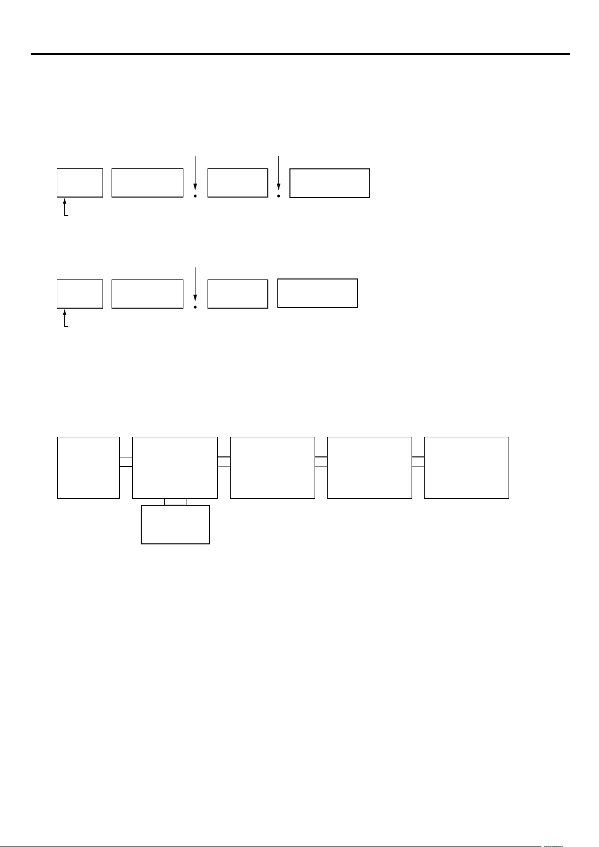
2-3-2 Example of address assignment
1) Example of a system consisting only of a main unit with 40 points
Main unit with 40 points
Unit No. 0
Input: 24 points
output: 16 points
(Word address)
%IW0.0 (WX0.0)
%IW0.1 (WX0.1)
%QW0.4 (WY0.4)
Input: 24 points
Output: 16 points
(Bit address)
0F
%IX0.0.0 to %IX0.0.15 (X0.00 to X0.0F)
%IX0.1.0 to %IX0.1.7 (X0.10 to X0.17)
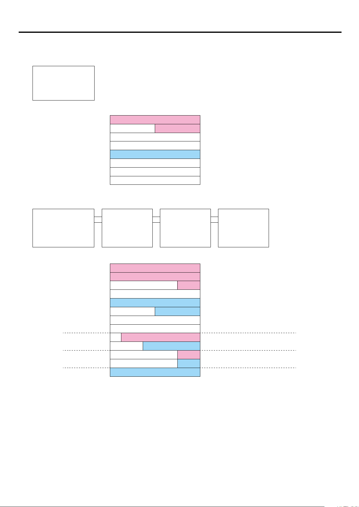
2) Example of a system in which expansion units are connected to a main unit with 60 points
Main unit with 60 points
Unit No. 0
Input: 36 points
output: 24 points
(Word address)
%IW0.0 (WX0.0)
%IW0.1 (WX0.1)
%IW0.2 (WX0.2)
Expansion
right side unit
Unit No. 1
Input: 14 points
output: 10 points
Expansion
right side unit
Unit No. 2
Input: 4 points
output: 4 points
0F
Input: 36 points
Expansion
right side unit
Unit No. 3
Output: 16 points
(Bit address)
%IX0.0.0 to %IX0.0.15 (X0.00 to X0.0F)
%IX0.1.0 to %IX0.1.15 (X0.10 to X0.1F)
%IX0.2.0 to %IX0.2.3 (X0.20 to X0.23)
%QW0.4 (WY0.4)
%QW0.5 (WY0.5)
%IW1.0 (WX1.0)
%QW1.1 (WY1.1)
%IW2.0 (WX2.0)
%QW2.1 (WY2.1)
%QW3.0 (WY3.0)
Output: 24 points
Input: 14 points
Output: 10 points
Output: 16 points
%QX0.4.0 to %QX0.4.15 (Y0.40 to Y0.4F)
%QX0.5.0 to %QX0.5.7 (Y0.50 to Y0.57)
%IX1.0.0 to %IX1.0.13 (X1.00 to X1.0D)
%QX1.1.0 to %QX1.1.9 (Y1.10 to Y1.19)
Input:
4 points
Output:
4 points
%IX2.0.0 to %IX2.0.3 (X2.00 to X2.03)
%QX2.1.0 to %QX2.1.3 (Y2.10 to Y2.13)
%QX3.0.0 to %QX3.0.15 (Y3.00 to Y3.0F)
2-9
Page 26
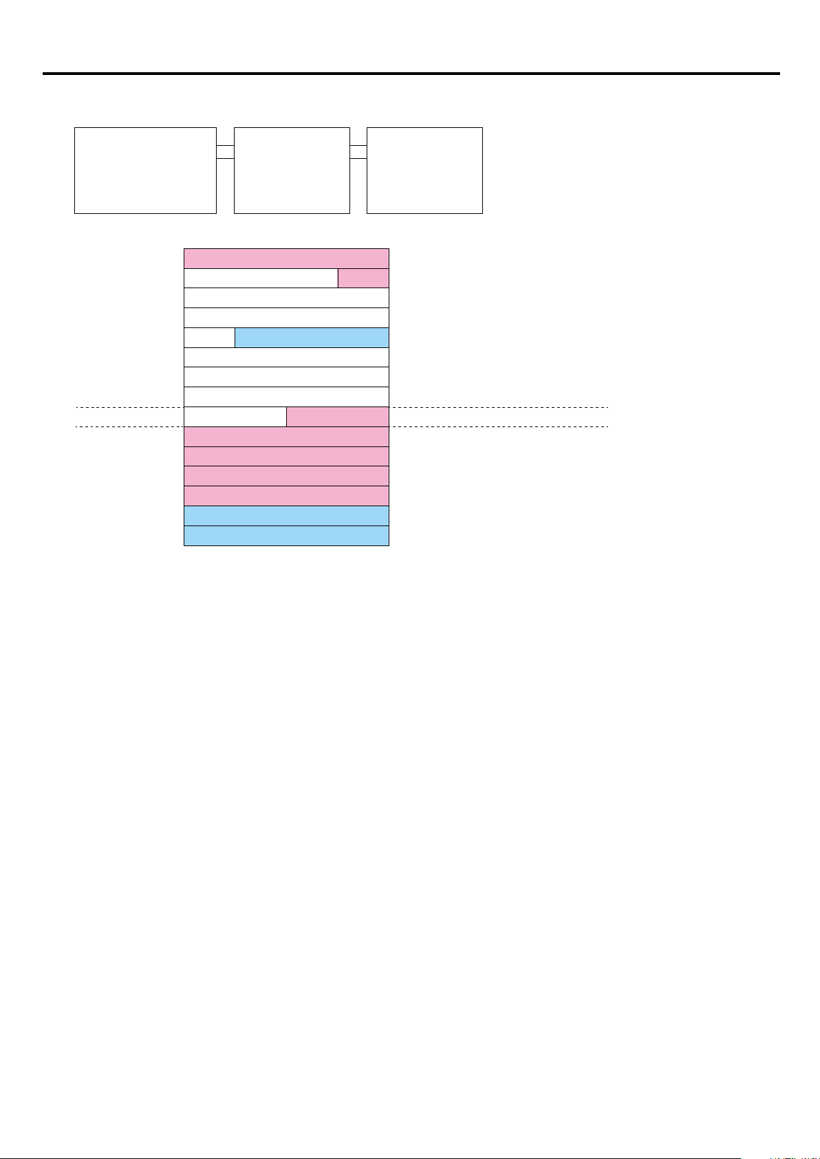
Section 2 System Conguration
3) Example of a system in which expansion units are connected to a main unit with 32 points
Main unit with 32 points
Unit No. 0
Input: 20 points
output: 12 points
(Word address)
%IW0.0 (WX0.0)
%IW0.1 (WX0.1)
%QW0.4 (WY0.4)
%IW1.0 (WX1.0)
%IW2.0 (WX2.0)
%IW2.1 (WX2.1)
%IW2.2 (WX2.2)
%IW2.3 (WX2.3)
%QW2.4 (WY2.4)
%QW2.5 (WY2.5)
Expansion
right side unit
Unit No. 1
Input: 8 points
Input: 20 points
Output: 12 points
Input: 8 points
Input: 4 words
Output: 2 words
Expansion
right side unit
Unit No. 2
Input: 4 words
output: 2 words
(Bit address)
0F
%IX0.0.0 to %IX0.0.15 (X0.00 to X0.0F)
%IX0.1.0 to %IX0.1.3 (X0.10 to X0.13)
%QX0.4.0 to %QX0.4.11 (Y0.40 to Y0.4B)
%IX1.0.0 to %IX1.0.7 (X1.00 to X1.07)
2-10
Page 27

Section 3 Specications
3-1 General Specications ............................................................................ 3-1
3-2 Main Unit Specications ......................................................................... 3-2
3-2-1 Performance specications ........................................................................3-2
3-2-2 Memory backup and internal battery specications....................................3-3
3-2-3 Calendar specications ..............................................................................3-3
3-3 Power supply specications................................................................... 3-4
3-3-1 AC power supply type .................................................................................3-4
3-3-2 DC power supply type ................................................................................3-4
3-4 Input specications ................................................................................. 3-5
3-4-1 DC input specications ............................................................................... 3-5
(1) Specications ............................................................................................. 3-5
(2) Input circuit conguration and external connection .................................... 3-6
3-5 Output Specications .............................................................................. 3-7
3-5-1 Transistor output specications .................................................................. 3-7
(1) Specications ............................................................................................. 3-7
(2) Output circuit conguration and external connection.................................. 3-8
(3) Speeding up transistor output circuits ........................................................ 3-9
3-5-2 Relay output specications ....................................................................... 3-10
(1) Specications ........................................................................................... 3-10
(2) Output circuit conguration and external connections .............................. 3-11
3-5-3 Output device protection and noise suppression in DO circuit ................. 3-12
(1) Protection of relay contacts and noise suppression ................................. 3-12
(2) Contact transfer ........................................................................................ 3-13
(3) Protection of transistor output and noise suppression.............................. 3-14
3-6 Analog Unit/Board Specications ........................................................ 3-15
3-6-1 Analog input unit (NA0AX06-MR) ............................................................. 3-15
(1) Specications ........................................................................................... 3-15
(2) Names ...................................................................................................... 3-15
3-6-2 Analog output unit (NA0AY02-MR) ........................................................... 3-16
(1) Specications ........................................................................................... 3-16
(2) Names ...................................................................................................... 3-16
3-6-3 Analog input/output unit (NA0AW06-MR) ................................................. 3-17
(1) Specications ........................................................................................... 3-17
(2) Names ...................................................................................................... 3-18
3-6-4 Analog output board (NA3AY02-MR) ....................................................... 3-19
(1) Specications ........................................................................................... 3-19
(2) Names ...................................................................................................... 3-19
Page 28

3-6-5 Analog input/output board (NA3AW03-MR) ............................................. 3-20
(1) Specications ........................................................................................... 3-20
(2) Names ...................................................................................................... 3-20
3-6-6 Thermocouple input unit (NA0AX02-TC/NA0AX06-TC/NA0AX16-TC) .... 3-21
(1) Specications ........................................................................................... 3-21
(2) Names ...................................................................................................... 3-22
3-6-7 Resistance thermometer element input unit (NA0AX06-PT) .................... 3-24
(1) Specications ........................................................................................... 3-24
(2) Names ...................................................................................................... 3-24
3-7 Communication Unit/Board Specications ......................................... 3-25
3-7-1 RS-232C/RS-485 general purpose communication board
(NA3LA-RS1) ............................................................................................ 3-25
(1) Specications ........................................................................................... 3-25
(2) Names ...................................................................................................... 3-25
3-7-2 RS-232C general purpose communication unit (NA0LA-RS3) ................. 3-26
(1) Specications ........................................................................................... 3-26
(2) Names ...................................................................................................... 3-26
3-7-3 RS-485 general purpose communication unit (NA0LA-RS5) ...................3-27
(1) Specications ........................................................................................... 3-27
(2) Names ...................................................................................................... 3-27
3-7-4 Ethernet communication board (NA3LA-ET1) /
Ethernet communication unit (NA0LA-ET1) ............................................. 3-28
(1) Specications ........................................................................................... 3-28
(2) Names ...................................................................................................... 3-28
3-8 Function Unit Specications ................................................................ 3-29
3-8-1 Load cell unit (NA0F-LC1) ........................................................................ 3-29
(1) Specications ........................................................................................... 3-29
(2) Names ...................................................................................................... 3-29
(3) External connection .................................................................................. 3-30
3-8-2 High-precision load cell unit (NA0FA-LC1) ............................................... 3-31
(1) Specications ........................................................................................... 3-31
(2) Names ...................................................................................................... 3-31
3-9 Temperature derating of main unit ....................................................... 3-32
(1) Main unit with 14/24 points ....................................................................... 3-32
(2) Main unit with 32/40 points ....................................................................... 3-32
(3) Main unit with 60 points ............................................................................ 3-33
3-10 Terminal Arrangement ......................................................................... 3-34
3-10-1 Main unit ................................................................................................. 3-34
(1) Main unit with 14 points
(8 points input / common, 2 points output / common x 3 circuits)............. 3-34
(2) Main unit with 24 points
(14 points input / common, 2 points output / common x 3 circuits,
4 points output / common) ........................................................................ 3-34
(3) Main unit with 32 points
(20 points input / common, 2 points output / common x 4 circuits,
4 points output / common) ........................................................................ 3-35
Page 29

(4) Main unit with 40 points
(24 points input / common, 2 points output / common x 4 circuits,
4 points output / common x 2 circuits) ...................................................... 3-35
(5) Main unit with 60 points
(36 points input / common, 2 points output / common x 4 circuits,
4 points output / common x 4 circuits) ...................................................... 3-36
3-10-2 Expansion unit ........................................................................................ 3-37
(1) Expansion unit with 8 points
(4 points input / common, 2 points output / common x 2 circuits)............. 3-37
(2) Expansion unit with input 8 points (8 points input / common)................... 3-37
(3) Expansion unit with output 8 points
(2 points output / common x 4 circuits) ..................................................... 3-37
(4) Expansion unit with output 16 points
(2 points output / common x 4 circuits, 4 points output / common
x 2 circuits) ............................................................................................... 3-37
(5) Expansion unit with 24 points
(14 points input / common, 2 points output / common x 3 circuits,
4 points output / common) ........................................................................ 3-38
(6) Expansion power supply unit .................................................................... 3-38
3-11 Names and Functions ......................................................................... 3-39
3-11-1 Main unit ................................................................................................. 3-39
(1) Names ...................................................................................................... 3-39
(2) Functions .................................................................................................. 3-40
3-11-2 Expansion unit ........................................................................................ 3-42
(1) Names ...................................................................................................... 3-42
(2) Functions .................................................................................................. 3-43
3-12 Dimensions .......................................................................................... 3-44
3-12-1 Main unit ................................................................................................. 3-44
(1) Main unit with 14/24 points ....................................................................... 3-44
(2) Main unit with 32/40 points ....................................................................... 3-44
(2) Main unit with 60 points ............................................................................ 3-45
3-12-2 Expansion unit ........................................................................................ 3-46
(1) Expansion unit with 8 points, AIO expansion unit, Load cell unit,
Expansion power supply unit, High-precision load cell unit ...................... 3-46
(2) Expansion unit with 16 points ................................................................... 3-46
(3) Expansion unit with 24 points, Temperature measurement unit 16CH ..... 3-47
(4) Communication unit .................................................................................. 3-47
(5) Communication board, AIO board ............................................................3-48
(6) Healthy unit ............................................................................................... 3-48
3-13 Mass ...................................................................................................... 3-49
(1) Main unit ................................................................................................... 3-49
(2) Expansion unit .......................................................................................... 3-49
(3) Expansion power supply unit .................................................................... 3-49
(4) Analog board/unit ..................................................................................... 3-49
(5) Communication unit/board ........................................................................ 3-50
(6) Function unit ............................................................................................. 3-50
Page 30

Section 3 Specications
3-1 General Specications
Item Specication Remark
Physical
environmental
conditions
Mechanical
service
conditions
Electrical
service
conditions
Operating ambient
temperature
Storage (transportation)
temperature
Relative humidity
Pollution degree 2 (Note 1)
Corrosion immunity Free from corrosive gases. Not stained with organic solvents
Operating altitude 2000 m or less above sea level (Transport condition: 70 kPa or more)
Vibration
Shock
Electrostatic discharge Contact discharge: ±4kV, Aerial discharge: ±8kV IEC 61000-4-2
Radiated,
radio-frequency,
electromagnetic eld
EFT/B (Electrical fast
transient/burst)
0 to +55°C (Note 4) IEC 61131-2
-25 to +70°C
20 to 95%RH, no condensation
(Transport condition: 5 to 95%RH, no condensation)
Half amplitude: 0.15mm, Constant acceleration: 19.6 m/s
Two hours for each of three mutually perpendicular axes, Total six
hours (Note 2) (Note 3)
Acceleration peak: 98 m/s
Three times for each of three mutually perpendicular axes
80 to 1000MHz (10V/m)
1.4 to 2.0 GHz (3V/m)
2.0 to 2.7 GHz (1V/m)
Equipment power, I/0 power, AC I/O (unshielded): ±2kV
Data communication, digital and analog I/O s’ (except AC unshielded
I/O): ±1kV
2
2
IEC 61000-4-3
IEC 61000-4-4
Lightning impulse surge
Conducted radio
frequency
Power frequency
magnetic eld
Construction Panel-mounted type (open equipment)
Cooling Air cooling
Notes:
1) Pollution degree 2: This pollution does not conduct usually, but under certain circumstances temporary conductivity occurs
due to condensation.
2) The unit is xed by screws to the control panel. When the unit is mounted to the DIN rail, care must be taken that
vibrations or shocks will not occur.
3) In an environment where repetitive or continuous vibration occurs, be sure to take vibration-proong measures.
4) See “3-9 Temperature derating of main unit.”
AC equipment power: ±2kV common mode, ±1kV differential mode
DC equipment power: ±0.5kV common mode, ±0.5kV differential mode
150kHz to 80MHz, 10V IEC 61000-4-6
50Hz, 30A/m IEC 61000-4-8
IEC 61000-4-5
3-1
Page 31

Section 3 Specications
3-2 Main Unit Specications
3-2-1 Performance specications
Item
Control system
Input/output connection method Direct input/output (local bus)
I/O control system
CPU 16-bit processor
Memory types Program memory, data memory, temporary memory
Programming language
Length of instructions Variable length (depending on language)
Program memory capacity (Note 2) 8192 steps 20480 steps
Program steps in a POU 8192 steps 16384 steps
I/O memory 512 words
Standard memory 4096 words 8192 words
Retain memory 2048 words 4096 words
User FB memory 4096 words 8192 words
User FB memory
Initial value setting memory
Memory
(Note 1)
System FB
memory
System memory 512 words
Special relay/register (standard) 4096 words
Special relay/register (retain) 4096 words
No. of tasks
No. of programs
Timer 256 points 512 points
Integrating timer 0 point 0 point
Counter 256 points 512 points
Edge detection 1024 points 2048 points
Others 512 words 1024 words
Specication
Main unit with 14/24 points Main unit with 32/40/60 points
Stored program,
Cyclic scanning system (default task), periodic task, event task
Whole: Scan batch refresh system
Digital I/O: Task synchronized refresh system
<When using D300win>
Conforming to IEC61131-3
IL language (Instruction List)
ST language (Structured Text)
LD language (Ladder Diagram)
FBD language (Function Block Diagram)
SFC elements (Sequential Function Chart)
4608 words 9216 words
5632 words 11264 words
Default tasks (Cyclic scanning): 1
Fixed cycle tasks + Event tasks: 15 in total
64 / Default task
8 / Fixed cycle task, Event task
<When using Standard Loader>
Original LD language (Ladder
Diagram)
Notes:
1) You can freely increase or decrease the area sizes of the standard memory, retain memory, user FB memory, and system
FB memory. The above table shows the default values.
2) The initial value setting area of the standard memory and retain memory is included.
3-2
Page 32

Section 3 Specications
3-2-2 Memory backup and internal battery specications
The primary battery built in the main unit cannot be replaced. When a voltage drop of the battery is detected, you need to
replace the main unit.
The battery connection switch is set to OFF at the factory shipment to save battery consumption. When you start using the main
unit, set the battery connection switch to ON to enable memory backup by the built-in battery.
For the details of the battery connection switch, see “3-11-1 Main unit” in “3-11 Names and Functions.”
Item Specication Remark
Backup area
Battery Graphite uoride lithium primary battery Built-in battery, 1000mA/h, Unreplaceable
Backup time 10 years or more Ambient temperature: 55°C
Battery voltage drop
detection function
Battery voltage read
function
Battery life Life of primary battery: 10 years
<Notes on battery connection switch>
When the battery connection switch is OFF, the battery voltage drop detection LED also blinks. Check the switch status.
Retain memory, retain attributed memory of
user FB and System FB instance memory,
RAS history, Calendar
Provided
(Updated approximately every 10 minutes
while the main power is ON.)
Provided
(Updated approximately every 10 minutes
while the main power is ON.)
Backup target parts: SRAM, RTC
• When a voltage drop of the battery is detected (*1), the
PWR/BAT LED blinks alternately in red and orange.
The battery error in the system memory is set ON.
• When detected that the battery voltage is normal (*2),
the PWR/BAT LED lights up in red. The battery error in
the system memory is set OFF.
*1 2.4V or less
(battery voltage A/D conversion value 492)
*2 2.4V or more
(battery voltage A/D conversion value 493)
• Battery voltage A/D conversion value is stored in the
special register “%MW1.61450 (WM61450).”
• Battery voltage
= Battery voltage A/D conversion value * 4.883 [mV]
* Battery voltage drop can be detected by an application.
<Notes on detection of battery voltage drop and primary battery life>
• The built-in graphite uoride lithium primary battery has a characteristic that its voltage is increased under a high ambient
temperature. Therefore, even if the battery voltage drop detection LED blinks at power-on of the main unit, it may turn OFF
as the temperature in the main unit rises while running.
• The remaining capacity of a graphite uoride lithium primary battery never recovers even if the ambient temperature is high.
If the ambient temperature is high and the battery remaining capacity is low, the battery voltage may rapidly drop as the
remaining capacity is consumed.
In addition, as a result of moisture absorption for a long period, self discharge of a graphite uoride lithium primary battery
may rapidly increase from some point to cause a rapid drop of the battery voltage.
• For the above reasons, if you conrm that the battery voltage drop detection LED blinks or when more than ten years have
passed since the date of shipment, promptly replace the main unit following the steps described in “5-2 Actions to be Taken
When Battery Voltage Drop is Detected” without turning off the power.
• If the battery voltage continues to decrease with the main power OFF, more and more data of the built-in SRAM can be
easily lost, which causes a memory backup error (retain memory loss) after the main power is turned ON. In addition, the
calendar may be stopped or delayed.
3-2-3 Calendar specications
Item Specication Remark
Range
Precision ±232 ppm (temperature: 25°C) ±20 sec/day
Time setting/change Loader, user application
Up to 31 Dec. 2069 23:59:59
3-3
Page 33

Section 3 Specications
3-3 Power supply specications
3-3-1 AC power supply type
Specication
Item
Rated input voltage
(tolerance)
Rated frequency
(tolerance)
Dropout tolerance 20ms or less
Power consumption 36W, 65VA 21W, 40VA
Inrush current 20A at 264V AC
Built-in fuse specication 2A, 250V AC (unreplaceable by users)
Power
supply
output
Insulation method Transformer/photocoupler
Dielectric strength 1500V AC, 1 minute
Insulation resistance 10MΩ or more (500V DC megger)
Internal 5V DC 5V DC ±5%, 1A (max.) 5V DC ±5%, 948mA (max.) 5V DC ±5%, 400mA (max.)
Internal 24V DC 24V DC ±10%, 400mA (max.) 24V DC ±10%, 350mA (max.) 24V DC ±10%, 250mA (max.)
Externally supplied
24V DC
Main unit
NA0PAooT-31C
100 to 240V AC
(85 to 264V AC)
50/60Hz
(47 to 63Hz)
24V DC ±10%, 400mA (max.) 24V DC ±10%, 337mA (max.) 24V DC ±10%, 250mA (max.)
Expansion unit
with power supply
NA0E24T-31
Expansion power supply
NA0S-2
3-3-2 DC power supply type
Specication
Item
Rated input voltage
(tolerance)
Dropout tolerance 10ms or less
Power consumption 24W 14W
Inrush current 20A at 24V DC
Built-in fuse specication 2.5A, 125V (unreplaceable by the user)
Internal 5V DC 5V DC ±5%, 1A (max.) 5V DC ±5%, 948mA (max.) 5V DC ±5%, 400mA (max.)
Power
supply
output
Insulation method Transformer/photocoupler
Dielectric strength 500V DC, 1 minute
Insulation resistance 10MΩ or more (500V DC megger)
Internal 24V DC 24V DC ±10%, 400mA (max.)
Externally supplied
24V DC
Main unit
NA0P
oooo
24V DC
(20.4 to 28.8V DC)
24V DC ±10%, 400mA (max.) 24V DC ±10%, 250mA (max.)
-34C
Expansion unit
with power supply
NA0E24R-34
24V DC ±10%,
337mA in total (max.)
Expansion power supply
NA0S-4
1.5A, 125V
(unreplaceable by users)
24V DC ±10%, 250mA (max.)
Notes:
The external 24V DC power supply output is not insulated from the internal 5V DC and the internal 24V DC.
If you need an insulated I/O power supply, externally prepare 24V DC power supply.
3-4
Page 34

Section 3 Specications
3-4 Input specications
3-4-1 DC input specications
(1) Specications
Function
Input signal
conditions
Input circuit
characteristic
High-speed
DC input
Rated voltage 24V DC
Voltage (tolerance) 26.4V DC
Ripple factor tolerance 5%
Input type Source, sink common (by external wiring)
Input current (at 24V DC) Approx. 9mA Approx. 6.5mA Approx. 4mA
Input impedance Approx. 2.7k
Operating
voltage
Input type DC type 1
Input delay
time
Maximum input frequency
/operating time
(Note 1)
OFF to ON 18.5 to 26.4V 19.5 to 26.4V 20.5 to 26.4V
ON to OFF 0 to 5V 0 to 5V 0 to 5V
Hardware 1µs or less 22µs or less 0.55ms or less 5.5ms or less
You can select any of the following values in the system
denition:
Digital lter
“No set,” 0.5μs, 1μs, 1.5μs (default), 2μs, 2.5μs, 3μs, 3.5μs,
10μs, 30μs, 100μs, 300μs, 1ms, 3ms, 3ms/10ms, 10ms, or
15ms
* Recommended to set at 1.5μs or more
200kHz/2.5µs
(Advance main unit)
100kHz/5µs
(Basic main unit)
Ω
Medium-speed
DC input
Approx. 3.7k
20kHz/25µs 0.83kHz/0.6ms –
Ω
Low-speed
DC input
Approx. 5.9k
Expansion
DC input
Ω
–
External wire connections
Input indication LED indicator turns on when input is “ON” and turns off when input is “OFF”.
Isolation method Photocoupler
Dielectric strength 1500V AC 1 minute (between input terminals and frame ground)
Insulation resistance 10MΩ or more with 500V DC megger (between input terminals and frame ground)
Derating condition Specied (Note 2) None
NA0PA14T-34C X0, 1 X2 to 7 – –
NA0PA24T-3oC X0, 1, 4, 5 X2, 3, 6 to 13 – –
NA0PA32T-3oC X0, 1, 4, 5, 8, 9 X2, 3, 6, 7, 10 to 15 X16 to 19 –
NA0PA40T-3oC X0, 1, 4, 5, 8, 9 X2, 3, 6, 7, 10 to 15 X16 to 23 –
Corresponding
terminal No.
NA0PA60T-3oC
NA0PB14R-34C X0, 1 X2 to 7 – –
NA0PB24R-34C X0, 1 X2 to 13 – –
NA0PB32R-34C X0, 1 X2 to 15 X16 to 19 –
NA0PB60R-34C X0, 1 X2 to 15 X16 to 35 –
Expansion unit – – –
Terminal block (M3 screw)
X0, 1, 4, 5, 8, 9, 12, 13X2, 3, 6, 7, 10, 11,
14, 15
X16 to 35 –
All inputs
Notes:
1) In A/B-phase input mode, the maximum input frequency becomes half.
2) See “3-9 Temperature derating of main unit.”
3-5
Page 35

Section 3 Specications
X0
X1
X3
External common line
Input device
External
power
supply
X2
X0
X3
X1 X2
External common line
Input circuit
External
power
supply
(2) Input circuit conguration and external connection
The 24V DC digital input circuits are available for high, medium and low speed. They all have the similar circuit structures but
with different response speeds. When making the connection of external digital input devices, the one ends of all input devices
(e.g. buttons and switches) are connected together and called the external common wire, while the other ends of input circuits
are connected to the input terminals X0, X1, X2, etc., of SPF. Then nish it by connecting the external common wiring and
internal common terminal S/S to the 24VDC power. When connecting the internal common terminal S/S to 24V+ (positive) and
the external common wire to 24V- (negative), then the circuit serves as a sink input. On the contrary, while exchange the wiring
of the above internal and external common will serve as a source input. The above wiring schemes can illustrated below:
• Wiring of source input
24V DC
SPF
(Not available when using
an expansion unit without
power supply.)
• Wiring of sink input
24V DC
+24V
24V DC
NPN
sensor
-
S/S
Internal
common
terminal
R2
R1
R2
X1 X2X0
R1
R2
R1
X3
R1
R2
PNP
sensor
SPF
+24V
-
24V DC
(Not available when using
an expansion unit without
power supply.)
S/S
Internal
common
terminal
R2
R1
X3
R1
R2
X0
R1
X1 X2
R1
R2
R2
3-6
Page 36

Section 3 Specications
3-5 Output Specications
3-5-1 Transistor output specications
(1) Specications
Item
Output
power supply
conditions
Output circuit
characteristic
Output protection
method
External wire connections Terminal block (M3 screw)
Rated voltage 12 to 24V DC
Rated voltage
(tolerance)
Output type Sink output
Max. load current
Voltage drop 0.6V 2.2V 2.2V
Response
time
Pulse output frequency
Leakage current in
OFF state
Output element Transistor output
Built-in fuse None
Others None
ON to OFF 2μs 30μs 30 to 32μs
OFF to ON 2μs 15μs 15 to 17μs
High-speed
output
5 to 30V DC
0.5A/point
(Note 1)
Max. 200kHz
(Note 3)
Max. 0.1mA / 30V DC
Medium-speed
output
Max. 20kHz
(Note 4)
Low-speed
output
– –
Expansion
output
0.5A/point
(Note 2)
Output indication LED indicator turns on when input is “ON” and turns off when output is “OFF”.
Isolation method Photocoupler
Dielectric strength 500V AC 1 minute (between output terminals and frame ground)
Insulation resistance 10MΩ or more with 500V DC megger (between output terminals and frame ground)
Derating condition Specied (Note 5) None
NA0PA14T-34C Y0 to 3 Y4, 5 – –
NA0PA24T-3oC Y0 to 3 Y4 to 7 Y8, 9 –
Corresponding
terminal No.
Notes:
1) The total of all points is “0.1A x No. of output points” or less.
Example: In the case of a unit with 40 points (No. of output points: 16 points), the total is 1.6A or less.
2) 0.1A/point for an expansion unit with 24 points (NA0E24T-31)
3) 100kHz for A/B-phase output mode
4) 8kHz for A/B-phase output mode
5) See “3-9 Temperature derating of main unit.”
NA0PA32T-3oC Y0 to 5 Y6, 7 Y8 to 11 –
NA0PA40T-3oC Y0 to 5 Y6, 7 Y8 to 15 –
NA0PA60T-3oC Y0 to 7 – Y8 to 23 –
Expansion unit – – – All outputs
3-7
Page 37

Section 3 Specications
2-point common output block4-point common output block
SPF
(2) Output circuit conguration and external connection
Transistor sink output
C2
1A
FUSE
Y2
Y3
C4
2A
FUSE
Y4
Y5
Y6
Y7
3-8
Page 38

Section 3 Specications
R
SPF
R: Dummy load
(3) Speeding up transistor output circuits
With the sink structure in a transistor circuit, when the transistor switches from ON to OFF, the junction capacitor between
transistor CE electrodes should be charged to near the load voltage VDD before it can stop the current running through the
photocoupler inside the load, which increase the OFF time and decrease the response speed. This problem can be solved by
adding a Dummy load to accelerate charging rate and speed up the working frequency of transistor output. For the transistor
output, Dummy load that are added to the high and medium-speed transistor output and generate a load current of 20 to 50mA
is adequate. For low speed transistor where its driving capability (0.5A) but speed is concerned, adding a Dummy load only
decreases its driving capability without any signicant improvement and hence is not recommended. The following diagram
shows how to add a Dummy load to transistor sink output.
Load
I: Load current
P
Y0
C0
R
I
N
VDD
I =
= 20 to 50mA
VDD
12 to 24V DC
3-9
Page 39

Section 3 Specications
3-5-2 Relay output specications
(1) Specications
Item Specication
Output power
supply conditions
Output circuit
characteristic
Output protection
method
External wire connections Terminal block (M3 screw)
Output indication LED indicator turns on when input is “ON” and turns off when output is “OFF”.
Isolation method Relay
Dielectric strength 1500V AC 1 minute (between output terminals and frame ground)
Insulation resistance
Rated voltage
(tolerance)
Output type Relay output
Max. load current
Response
time
Min. make/break current 5V DC, 2mA
Output element Relay output
On/off times Max. 1800 times/hour
Built-in fuse None
Surge absorption circuit None
Others None
ON to OFF 10ms or less
OFF to ON 10ms or less
250V AC or less / 30V DC or less
2A/common, 4A/common (resistive load)
80VA (AC) / 24VA (DC) (inductive load)
10MΩ or more with 500V DC megger
(between output terminals and frame ground)
Derating condition Specied (Note 1)
Notes:
1) See “3-9 Temperature derating of main unit.”
3-10
Page 40

Section 3 Specications
SPF
(2) Output circuit conguration and external connections
Each relay can provide current up to 2A. The maximum rated current in all output commons of SPF is 4A. Its mechanical lifetime
can reach up to 2 million times. The lifetime also varies depending on working voltage, load type (power factor cosψ) and
contact current. In the case of pure resistive load (cosψ=1.0) at 120VAC and 2A, the lifetime of contacts is about 250 thousand
times. While for high inductive or capacitive load with cosψ up to 0.2 and current within 1A, the lifetime decreases rapidly to
about 50 thousand times (AC200V) or 80 thousand times (AC120V).
AC/DC
power
supply
A4
Fuse
)
4
Operation (x10
AC/DC
power
supply
Life curve
Contact current (A)
A4
Fuse
resistive
resistive
3-11
Page 41

Section 3 Specications
Surge current welds contacts.
PLC output
3-5-3 Output device protection and noise suppression in DO circuit
Since the digital output circuits are mainly used for the ON/OFF switching operation, the output components such as relays,
transistors and TRIAC can be deemed as kinds of switch components. Normally, surge currents or counter-electromotive force
voltages are generated during the ON/OFF operation of these switch components. The effect of surge currents or counterelectromotive force voltages is particularly serious when heavy capacitive or inductive loads are incorporated, which may cause
damage to the output components or generate noises in other electronic circuits and equipment. Special consideration should
be given to relays and transistors when they are used in high power applications or connected with capacitive or inductive loads
and are described in the following:
(1) Protection of relay contacts and noise suppression
Because the relay contacts are used to contact switch components having extremely low resistance, the surge current IR
generated instantly upon turning on the relay is normally pretty strong (even if the steady load current is very small). Under such
strong surge, the contact tends to melt and stick due to extreme temperature in such a way that the relay cannot trip when it is
disconnected. In addition, when the relay connections are OFF, large di/dt is generated because of the instantaneous change
from low resistance to open circuit (∞) soon after following the tripping of contact. As a result, an extremely strong counter-
electromotive force voltage is induced, which creates sparks between the electrodes of two relay contacts and results in poor
contact due to carbon deposits. Among those three output components, either in ON or OFF state, very serious interference can
be caused by the surge current or the counter-electromotive of the relay. The solutions to this problem are listed as follows:
1) Suppression of surge current
Connect a small resistor R in series to lower the surge current, but note that too large R will affect the driving capability or cause
too much voltage drop.
relay
Load
I s
Is
I r
Ir
Electric
circuits
R (note power dissipation P = Is2R and voltage drop V = IsR)
Ir max
Ir max of relay in SPF = 5A
C
VDD
R
V
R
VDD
3-12
Page 42

Section 3 Specications
Suppress by a diode + Zener in DC power load (for high power and frequent ON/OFF)
2) Suppression of counter-electromotive force
For the inductive load, whether in AC or DC power, suppression devices must be connected in parallel to both its ends to protect
the relay contacts and lower noise interference. The schematic diagrams for AC and DC powers are shown below, respectively:
PLC Relay output
R
PLC Relay output
R
Suppress by a diode in DC power load (for low power)
PLC Relay output
R
Inductive load
RC
Scheme of AC power load
Inductive load
D
Inductive load
D
ZD
R: 100~120
C: 0.1 to 0.24uF
D: 1N4001 diode or
VDC
equivalent device
D: 1N4001 diode or
equivalent device
VDC
ZD: 9V Zener, 5W
(2) Contact transfer
Contact transfer refers to a phenomena in which one side of contact melts or evaporates and is transferred to the other side
because of on/off operation of the DC load. As the number of on/off times increases, the protruded portion on one contact grows
and the embossed portion on other contact becomes correspondingly large. Eventually the two contacts are locked as if contact
melting occurred. This phenomena may occur within the ratings of relay contacts. In particular, when a relay is used to turn on
and off a capacitive load, this phenomena may occur. In this case, use a resistor to suppress inrush current.
3-13
Page 43

Section 3 Specications
Suppress by a diode + Zener (high power and frequent ON/OFF)
(3) Protection of transistor output and noise suppression
The transistor output in SPF already includes Zener diode for counter-electromotive force, which is sufcient for low power
inductive load and medium frequency of ON/OFF application. In conditions of high power or frequent ON/OFF, please construct
another suppression circuit to lower noise interference and prevent voltage from exceeding the limit or overheating that may
damage the transistor output circuit.
PLC Relay output
PLC Relay output
Inductive load
D
Suppress by a diode (for low power)
Inductive load
D
ZD
VDC
D: 1N4001 diode or
equivalent device
D: 1N4001 diode or
equivalent device
VDC
ZD: 9V Zener, 5W
3-14
Page 44

Section 3 Specications
Terminal block
3-6 Analog Unit/Board Specications
3-6-1 Analog input unit (NA0AX06-MR)
(1) Specications
Item Specication
Type NA0AX06-MR
No. of input channels 6 channels
Input impedance Voltage: 63.2 kW, Current: 250
Maximum allowable input Voltage: ±15V, Current: 30mA
Input range
Resolution 12 bits or 14 bits (Set for individual channels by the program loader.)
Overall accuracy ±1% *1
A/D conversion value INT type
Sampling period Synchronized with the scan of the main unit.
Moving average 1 to 16 times (Set for individual channels by the program loader.)
External wire connections 8-pole terminal block (M3) x 2, Tightening torque: 0.59 to 0.78 N·m
Applicable wire size AWG#22-18 * Be sure to use shielded twisted pair cables.
Status indication 5V power supply display, ON when normal (red)
Isolation method Not isolated
Occupied words 6 words
External power supply 24V DC, 53mA *Wiring length: 10m or less
Internal current consumption 5V DC, 25mA
Dimensions 40 (W) x 90 (H) x 80 (D) (mm)
-10 to +10V, -5 to +5V, 0 to 10V, 0 to 5V
-20 to 20mA, -10 to 10mA, 0 to 20mA, 0 to 10mA
(Collectively set for all channels by the jumper pin in the unit)
W
*1 The overall accuracy is the specication for when noise described in “Electrical service conditions” is not applied.
If noise is applied, the overall accuracy may exceed the above specication.
(2) Names
<Signal assignment>
Expansion connector (IN)
Status indication LED
* For the detailed specications of and how to use the analog input unit (Type: NA0AX06-MR), refer to the user’s manual “Analog
Unit (FEH527).”
Expansion connector (OUT)
Terminal block
3-15
Page 45

Section 3 Specications
Terminal block
3-6-2 Analog output unit (NA0AY02-MR)
(1) Specications
Item Specication
Type NA0AY02-MR
No. of output channels 2 channels
External load resistance Voltage output: 500 W to 1 MW, Current output: 0 to 500 W or less
Analog output range
Resolution 14 bits
Overall accuracy ±1%
Data type of digital output value INT type
Output period Synchronized with the scan of the main unit.
External wire connections 8-pole terminal block (M3) x 2, Tightening torque: 0.59 to 0.78 N·m
Applicable wire size AWG#22-18 * Be sure to use shielded twisted pair cables.
Status indication 5V power supply display, ON when normal (red)
Isolation method Not isolated
Occupied words 2 words
External power supply 24V DC, 90mA *Wiring length: 10m or less
Internal current consumption 5V DC, 33mA
Dimensions 40 (W) x 90 (H) x 80 (D) (mm)
-10 to +10V, -5 to +5V, 0 to 10V, 0 to 5V
-20 to 20mA, -10 to 10mA, 0 to 20mA, 0 to 10mA
(Collectively set for all channels by the jumper pin in the unit)
(2) Names
<Signal assignment>
Expansion connector (IN)
Status indication LED
* For the detailed specications of and how to use the analog output unit (Type: NA0AY02-MR), refer to the user’s manual “Analog
Unit (FEH527).”
NA0AY02-MR
Expansion connector (OUT)
Terminal block
3-16
㻺㻭㻜㻭㼅㻜㻞㻙㻹㻾
Page 46

Section 3 Specications
3-6-3 Analog input/output unit (NA0AW06-MR)
(1) Specications
Item Specication
Type NA0AW06-MR
No. of input channels 4 channels
Input impedance Voltage: 63.2 kW, Current: 250
Maximum allowable input Voltage: ±15V, Current: 30mA
Input range
Resolution 12 bits or 14 bits (Set for each channel by the program loader.)
Overall accuracy ±1% *1
A/D conversion value INT type
Sampling period Synchronized with the scan of the main unit.
Moving average 1 to 16 times (Set for individual channels by the program loader.)
No. of output channels 2 channels
External load resistance Voltage output: 500 W to 1 MW, Current output: 0 to 500 W or less
Analog output range
Resolution 14 bits
Overall accuracy ±1%
Data type of digital output value INT type
Output period Synchronized with the scan of the main unit.
-10 to +10V, -5 to +5V, 0 to 10V, 0 to 5V
-20 to 20mA, -10 to 10mA, 0 to 20mA, 0 to 10mA
(Collectively set for all channels by the jumper pin in the unit)
-10 to +10V, -5 to +5V, 0 to 10V, 0 to 5V
-20 to 20mA, -10 to 10mA, 0 to 20mA, 0 to 10mA
(Collectively set for all channels by the jumper pin in the unit)
W
External wire connections 8-pole terminal block (M3) x 2, Tightening torque: 0.59 to 0.78 N·m
Applicable wire size AWG#22-18 * Be sure to use shielded twisted pair cables.
Status indication 5V power supply display, ON when normal (red)
Isolation method Not isolated
Occupied words 6 words
External power supply 24V DC, 103mA *Wiring length: 10m or less
Internal current consumption 5V DC, 35mA
Dimensions 40 (W) x 90 (H) x 80 (D) (mm)
*1 The overall accuracy is the specication for when noise described in “Electrical service conditions” is not applied.
If noise is applied, the overall accuracy may exceed the above specication.
3-17
Page 47

Section 3 Specications
Terminal block
(2) Names
<Signal assignment>
Expansion connector (IN)
Status indication LED
NA0AW06-MR
* For the detailed specications of and how to use the analog input/output unit (Type: NA0AW06-MR), refer to the user’s manual
“Analog Unit (FEH527).”
Expansion connector (OUT)
Terminal block
3-18
Page 48

Section 3 Specications
<Signal assignment>
3-6-4 Analog output board (NA3AY02-MR)
(1) Specications
Item Specication
Type NA3AY02-MR
No. of output channels 2 channels
External load resistance Voltage output: 1k W to 1MW, Current output: 0 to 500 W or less
Analog output range
Resolution 12 bits
Overall accuracy ±1%
Data type of digital output value INT type
Output period Synchronized with the scan of the main unit.
External wire connections 5-pole European-style terminal block (M2) x 1, Tightening torque: 0.2 N·m
Applicable wire size AWG#28-16 * Be sure to use shielded twisted pair cables.
Status indication None
Isolation method Not isolated
Occupied words 2 words
Internal current consumption 5V DC, 223mA
*1 Screw tightening torque for mounting the board on a main unit: 0.2 N·m
0 to +10V
0 to 20mA
* Selectable by wiring of the terminal block.
(2) Names
VO0+
IO0+
VO1+
IO1+
GND
1) Terminal block
* For the detailed specications of and how to use the analog output board (Type: NA3AY02-MR), refer to the user’s manual
“Analog Unit (FEH527).”
3-19
Page 49

Section 3 Specications
VO0+
1) Terminal block
<Signal assignment>
3-6-5 Analog input/output board (NA3AW03-MR)
(1) Specications
Item Specication
Type NA3AW03-MR
No. of input channels 2 channels
Input impedance Voltage input: 100 kW, Current input: 125
Maximum allowable input Voltage: ±15V, Current: 30mA
Analog input range
Resolution 14 bits (Set for each channel by the program loader.)
Overall accuracy ±1% *1
A/D conversion value INT type
Sampling cycle Synchronized with the scan of the main unit.
Moving average 1 to 16 times (Set for individual channels by the program loader.)
No. of output channels 1 channel
External load resistance Voltage output: 2 kW to 1 MW, Current output: 0 to 500 W or less
Analog output range
Resolution 12 bits
Overall accuracy ±1%
Data type of digital output value INT type
Output cycle Synchronized with the scan of the main unit.
0 to +10V
0 to 20mA
* Selectable by wiring of the terminal block.
0 to +10V
0 to 20mA
* Selectable by wiring of the terminal block.
W
External wire connections 5-pole European-style terminal block (M2) x 1, Tightening torque: 0.2 N·m
Applicable wire size AWG#28-16 * Be sure to use shielded twisted pair cables.
Status indication None
Isolation method Not isolated
Occupied words 3 words
Internal current consumption 5V DC, 158mA
*1 The overall accuracy is the specication for when noise described in “Electrical service conditions” is not applied.
If noise is applied, the overall accuracy may exceed the above specication.
*2 Screw tightening torque for mounting the board on a main unit: 0.2 N·m
(2) Names
VI0+
IO0+
GND
II0+
VI1+
II1+
GND
* For the detailed specications of and how to use the analog input/output board (Type: NA3AW03-MR), refer to the user’s
manual “Analog Unit (FEH527).”
3-20
Page 50

Section 3 Specications
3-6-6 Thermocouple input unit (NA0AX02-TC/NA0AX06-TC/NA0AX16-TC)
(1) Specications
Item Specication
Type NA0AX02-TC NA0AX06-TC NA0AX16-TC
No. of input channels 2 channels 6 channels 16 channels
Resolution 0.1°C or 1°C *1
Thermocouple type J, K, R, S, E, T, B, N (Collectively set for all channels by the program loader)
Temperature measurement
range
Cold junction automatic
compensator
Overall accuracy
Data type of
A/D conversion value
Sampling period
Moving average No moving average / 2 / 4 / 8 times
External wire connections 8-pole European-style terminal block (M2) x 2,
Applicable wire size AWG#28-16 AWG#22-18
J: -200.0 to 1200.0°C -328.0 to 2192.0°F
K: -200.0 to 1200.0°C -328.0 to 2192.0°F
T: -190.0 to 380.0°C -310.0 to 716.0°F
E: -190.0 to 1000.0°C -310.0 to 1832.0°F
N: -200.0 to 1000.0°C -328.0 to 1832.0°F
B: 350.0 to 1800.0°C 622.0 to 3272.0°F
R: 0.0 to 1800.0°C 32.0 to 3272.0°F
S: 0.0 to 1700.0°C 32.0 to 3092.0°F
Built in the unit
± (1% + 1°C) *2
INT type
1 second (high speed) or
2 seconds (low speed)
(Collectively set [high speed or low speed] for all channels by the program loader.)
(Collectively set for all channels by the program loader.)
Tightening torque: 0.2 N·m
2 seconds (high speed) or
4 seconds (low speed)
3 seconds (high speed) or
6 seconds (low speed)
18-pole terminal block (M3) x 2,
Tightening torque:
0.59 to 0.78 N·m
Status indication 5V power supply display, ON when normal (red)
Isolation method Transformer (power supply) and photocoupler (signal) Not isolated
Occupied words 2 words 6 words 16 words
External power supply
Internal current
consumption
Dimensions 40 (W) x 90 (H) x 80 (D) (mm) 90 (W) x 90 (H) x 80 (D) (mm)
*1 The resolution is determined by the setting of the “sampling period” in the parameter.
When the resolution is 1°C: Set to “high speed.”
When the resolution is 0.1°C: Set to “low speed.”
*2 The overall accuracy is the specication for when noise described in “Electrical service conditions” is not applied.
If noise is applied, the overall accuracy may exceed the above specication.
24V DC, 21mA 24V DC, 29mA 24V DC, 58mA
*Wiring length: 10m or less
5V DC, 30mA
3-21
Page 51

Section 3 Specications
Terminal block
Terminal block
(2) Names
1) NA0AX02-TC
<Signal assignment>
Expansion connector (IN)
Status indication LED
2) NA0AX06-TC
Expansion connector (IN)
Expansion connector (OUT)
Terminal block
<Signal assignment>
Expansion connector (OUT)
Status indication LED
Terminal block
3-22
Page 52

Section 3 Specications
2) Terminal block
3) NA0AX16-TC
Expansion
connector (IN)
1) Status indication LED
Expansion
connector (OUT)
Nameplate
2) Terminal block
<Signal assignment>
* For the detailed specications of and how to use the thermocouple input unit (Type: NA0AX02-TC/NA0AX06-TC/NA0AX16-TC),
refer to the user’s manual “Analog Unit (FEH527).”
3-23
Page 53

Section 3 Specications
2) Terminal block
3-6-7 Resistance thermometer element input unit (NA0AX06-PT)
(1) Specications
Item Specication
Type NA0AX06-PT
No. of analog input channels 6 channels
Resolution 0.1°C or 1°C *1
Applicable resistance thermometer
element
Temperature measurement range
Overall accuracy ±1% *2
Resistance of input wiring 20Ω or less
Data type of A/D conversion value INT type
Sampling period
Moving average
External wire connections 8-pole terminal block (M3) x 2, Tightening torque: 0.59 to 0.78 N·m
Applicable wire size AWG#22-18 * Be sure to use shielded twisted pair cables.
Status indication 5V power supply display, ON when normal (red)
Isolation method Not isolated
Occupied words 6 words
External power supply 24V DC, 16mA *Wiring length: 10m or less
Internal current consumption 5V DC, 32mA
Dimensions 40 (W) x 90 (H) x 80 (D) (mm)
Pt100, Pt1000 (JIS or DIN)
Pt100: -200.0 to 850.0°C (-328.0 to 1562.0°F)
Pt1000: -200.0 to 600.0°C (-328.0 to 1112.0°F)
1 second (high speed) or 2 seconds (low speed)
(Collectively set for all channels by the program loader.)
No moving average / 2 / 4 / 8 times
(Collectively set for all channels by the program loader.)
*1 The resolution is determined by the setting of the “sampling period” in the parameter.
When the resolution is 1°C: Set to “high speed.”
When the resolution is 0.1°C: Set to “low speed.”
*2 The overall accuracy is the specication for when noise described in “Electrical service conditions” is not applied.
If noise is applied, the overall accuracy may exceed the above specication.
(2) Names
<Signal assignment>
Expansion connector (IN)
1) Status indication LED
2) Terminal block
Expansion connector (OUT)
Nameplate
* For the detailed specications of and how to use the resistance thermometer element input unit (Type: NA0AX06-PT), refer to
the user’s manual “Analog Unit (FEH527).”
3-24
Page 54

Section 3 Specications
Inch screw
9
6
G
3-7 Communication Unit/Board Specications
3-7-1 RS-232C/RS-485 general purpose communication board (NA3LA-RS1)
(1) Specications
Item Specication
Interface RS-232C 1 channel (PORT1) RS-485 1 channel (PORT2)
Synchronization method Start-stop synchronous transmission
Transmission speed 1200/2400/4800/9600/19200/38400/57600/115200
Transmission distance Max. 15m Max. 1km (19200bps or less)
No. of connectable units 1:1 1:15 (Max.)
Connection method D-sub, 9-pin connector (female) 3-pole European-style terminal block
Transmission code
Binary (without code conversion) or
ASCII (with code conversion), EBCDIC (with code conversion)
Hardware Vertical parity (parity bit), framing, overrun error
Error control
Software Horizontal parity (BCC)
Bit send sequence From the lower-order bit (from LSB to MSB)
Data length which can be
transmitted or received at one
Max. 512 bytes (Depending on the mode)
time (viewed from the PLC)
Internal current consumption 5V DC, 55mA
Occupied words 0 word
*2 Screw tightening torque for mounting the board on a main unit: 0.2 N·m
(2) Names
RS-485 transmission status indication LED
RS-485 terminal block
PORT2
TX
RX
TX
RX
RS-485 terminating resistor switch
* Inside the surface cover
PORT1
<RS-232C connector pin arrangement>
Pin No. Signal name Description
1 – Not connected
5
1
2 TXD Send data
3 RXD Receive data
4 – Not connected
5 SG Signal ground
6 – Not connected
7 CTS Clear to send
8 RTS Request to send
9 – Not connected
RS-232C connector
<RS-485 terminal block arrangement>
+
-
Signal
name
+ (D+) RS-485 send/receive +
- (D-) RS-485 send/receive -
G (SG) Signal ground
Description
* For the detailed specications of and how to use the RS-232C/RS-485 general purpose communication board (Type:
NA3LA-RS1), refer to the user’s manual “General Purpose Communication (FEH528).”
3-25
Page 55

Section 3 Specications
Inch screw
9
6
3-7-2 RS-232C general purpose communication unit (NA0LA-RS3)
(1) Specications
Item Specication
Interface RS-232C 2 channels (PORT3, PORT4)
Synchronization method Start-stop synchronous transmission
Transmission speed 1200/2400/4800/9600/19200/38400/57600/115200
Transmission distance Max. 15km
No. of connectable units 1:1
Connection method D-sub, 9-pin connector (female)
Transmission code
Binary (without code conversion) or
ASCII (with code conversion), EBCDIC (with code conversion)
Hardware Vertical parity (parity bit), framing, overrun error
Error control
Software Horizontal parity (BCC)
Bit send sequence From the lower-order bit (from LSB to MSB)
Data length which can be
transmitted or received at one
Max. 512 bytes (Depending on the mode)
time (viewed from the PLC)
Internal current consumption 5V DC, 18mA
Occupied words 0 word
(2) Names
RS-232C connector
RS-485 transmission status indication LED
<RS-232C connector pin arrangement>
Pin No. Signal name Description
1 – Not connected
5
1
2 TXD Send data
3 RXD Receive data
4 – Not connected
5 SG Signal ground
6 to 9 – Not connected
* For the detailed specications of and how to use the RS-232C general purpose communication unit (Type: NA0LA-RS3), refer
to the user’s manual “General Purpose Communication (FEH528).”
3-26
Page 56

Section 3 Specications
G
3-7-3 RS-485 general purpose communication unit (NA0LA-RS5)
(1) Specications
Item Specication
Interface RS-485 2 channels (PORT3, PORT4)
Synchronization method Start-stop synchronous transmission
Transmission speed 1200/2400/4800/9600/19200/38400/57600/115200
Transmission distance Max. 1km (19200bps or less)
No. of connectable units 1:15 (Max.)
Connection method 3-pole European-style terminal block
Transmission code
Binary (without code conversion) or
ASCII (with code conversion), EBCDIC (with code conversion)
Hardware Vertical parity (parity bit), framing, overrun error
Error control
Software Horizontal parity (BCC)
Bit send sequence From the lower-order bit (from LSB to MSB)
Data length which can be
transmitted or received at one
Max. 512 bytes (Depending on the mode)
time (viewed from the PLC)
Internal current consumption 5V DC, 95mA
Occupied words 0 word
(2) Names
RS-485 terminal block
+
TX
-
G
RX
T N
<RS-485 terminal block arrangement>
+
-
RS-485 terminating resistor switch
PORT3 (RS485)PORT4 (RS485)
+
-
G
T N
NA0LA-RS5
TX
RX
Signal
name
Description
+ (D+) RS-485 send/receive +
- (D-) RS-485 send/receive -
G (SG) Signal ground
* For the detailed specications of and how to use the RS-485 general purpose communication unit (Type: NA0LA-RS5), refer to
the user’s manual “General Purpose Communication (FEH528).”
3-27
Page 57

Section 3 Specications
Ethernet status indication LED
3-7-4 Ethernet communication board (NA3LA-ET1) / Ethernet communication unit (NA0LA-ET1)
(1) Specications
Item Specications
Interface 10BASE-T 100BASE-TX
Transmission speed 10 Mbps 100 Mbps
Medium (physical specication) IEEE802.3u
AUTO MDI/MDI-X Not supported
Interface changeover system Auto negotiation (automatic changeover)
Transmission medium Twisted pair cable
Max. segment length 100m
Max. number of nodes 1 node / segment
General purpose
communication
Loader communication
Communication
function
Access method CSMA/CD
Transmission protocol TCP/IP, UDP/IP, ICMP (TYPE = 0, 3, 8), ARP
Max. number of simultaneous
communicable nodes
(number of communication ports)
Transmission code Binary only
Internal current consumption NA3LA-ET1: DC5V **mA, NA0LA-ET1: DC5V **mA
Occupied words 0 word
(Server operation)
Loader communication
(Client operation)
Communication between the PLC and other nodes is performed by using TCP/IP
or UDP/IP protocol. Because of free data format, it is possible to communicate with
all kinds of nodes.
Communication with a POD or loader, host PC is performed by a loader command.
No communication program is required on the PLC side.
The data memory in the target device (another SPH or SPF) is read or written.
“R_READ” (for reading data) and “R_WRITE” (for writing data) FBs are used for
communication.
Start these FBs to send or receive a loader command from the self station to the
target device.
8 stations / physical port
Note: The maximum number of communication ports that one CPU can
simultaneously open is 16 when using both an Ethernet front board and a
left side unit.
However, responses of communication deteriorate as the number of
communication ports per CPU increases.
* Screw tightening torque for mounting the board on a main unit: 0.2 N·m
(2) Names
<NA3LA-ET1>
Ethernet status indication LED
Ethernet connector
* For the detailed specications of and how to use the Ethernet communication board (NA3LA-ET1) and Ethernet communication
unit (NA0LA-ET1), refer to the user’s manual “SPF Ethernet Communication (FEH630).”
3-28
Ethernet connector
Page 58

Section 3 Specications
Terminal block
3-8 Function Unit Specications
3-8-1 Load cell unit (NA0F-LC1)
(1) Specications
Item Specication
No. of input channels 1 channel
Input range
Resolution 16 bits (including a sign bit)
Digital conversion value 0 to 25,000 (INT type)
0 to 2mV/V, 0 to 5mV/V, 0 to 10mV/V, 0 to 20mV/V
(Set by the program loader.)
Load cell applied voltage 5V DC, 100
Sampling period 5/10/25/30/60/80Hz (Set by the program loader.)
Moving average No moving average / 2 / 4 / 8 times (Set by the program loader.)
Nonlinearity 0.01% for full scale (at an ambient temperature of 25°C)
Accuracy
External wire connections 8-pole terminal block (M3) x 2, Tightening torque: 0.59 to 0.78 N·m
Status indication 5V power supply display, ON when normal (red)
Isolation method Transformer (power supply) and photocoupler (signal)
Occupied words 1 word
External power supply 24V DC, 48mA
Internal current consumption 5V DC, 32mA
Zero drift 0.2µV/°C
Gain drift 10ppm/°C
W
(2) Names
Expansion connector (IN)
Status indication LED
<Signal assignment>
Expansion connector (OUT)
Terminal block
3-29
Page 59

Section 3 Specications
16
NA0F-LC1
(3) External connection
24V+
24V-
24V
-bit Da ta
24-Bit
Δ-Σ
A/D
+5V
+EXC
CH0+
CH0-
-EXC
+
-
R
R
Load Cell
R
R
3-30
Page 60

Section 3 Specications
Status indication LED
Terminal block
3-8-2 High-precision load cell unit (NA0FA-LC1)
(1) Specications
Item Specication
No. of input channels 1 channel
Resolution 24 bits (including a sign bit)
Data type of digital conversion value INT type, DINT type
Load cell applied voltage 5V DC, 350 Ω
Sampling period 100 times/second
Max. measured voltage -1mV to 39mV
Input sensitivity, resolution 0.15µV/d or more (d = minimum scale) 1/60000
External wire connections 8-pole terminal block (M3) x 2, Tightening torque: 0.59 to 0.78 N·m
Applicable wire size AWG#22-18 * Be sure to use shielded twisted pair cables.
5V power supply display, ON when normal (red)
Status indication
Isolation method Transformer (power supply) and photocoupler (signal)
Stable indicator (MD), Zero-point indicator (ZRO), Net weight indicator (NET),
Gross weight indicator (GRS)
Occupied words 0 word
Parameter storage area Calibration parameters and set values are saved in the internal EEPROM.
External power supply 24V DC, 48mA *Wiring length: 10m or less
Internal current consumption 5V DC, 120mA
(2) Names
<Signal assignment>
Expansion connector
Terminal block
* For the detailed specications of and how to use the high-precision load cell unit (Type: NA0FA-LC1), refer to the user’s
manual “High-precision Load Cell Unit (FEH530).”
3-31
Page 61

Section 3 Specications
(No. of simultaneous
A
(AC power supply/
24V DC power supply,
transistor output [0.1A])
Main unit with 14 points
Main unit with 24 points
ON points)
(No. of simultaneous
ON points)
Basic main unit
(24V DC power supply,
relay output [1A])
(No. of simultaneous
A
(AC power supply/
24V DC power supply,
transistor output [0.1A])
Main unit with 32 points
Main unit with 40 points
ON points)
Basic main unit
(24V DC power supply,
relay output [1A])
3-9 Temperature derating of main unit
SPF main units have temperature derating limits for the No. of simultaneous ON points.
Expansion units have no temperature derating limits.
(1) Main unit with 14/24 points
dvance main unit
60°C
50°C
40°C
temperature
Ambient operating
30°C
20°C
0%
(0 point)
60°C
50°C
40°C
temperature
Ambient operating
30°C
20°C
0%
(0 point)
No limit
50%
(7 points)
No limit
50%
(7 points)
Simultaneous
ON rate
100%
(14 points)
(No. of simultaneous
ON points)
Simultaneous
ON rate
100%
(14 points)
(No. of simultaneous
60°C
50°C
40°C
temperature
Ambient operating
30°C
20°C
0%
(0 point)
60°C
50°C
40°C
temperature
Ambient operating
30°C
20°C
0%
(0 point)
50%
(12 points)
No limit
50%
(12 points)
16 points
100%
(24 points)
ON points)
100%
(24 points)
°C
51
Simultaneous
ON rate
Simultaneous
ON rate
(2) Main unit with 32/40 points
dvance main unit
60°C
50°C
40°C
temperature
Ambient operating
30°C
20°C
0%
(0 point)
60°C
50°C
40°C
temperature
Ambient operating
30°C
20°C
0%
(0 point)
(16 points)
(16 points)
50%
50%
16 points
(32 points)
(32 points)
°C
46
Simultaneous
ON rate
100%
(No. of simultaneous
ON points)
30 points
°C
54
Simultaneous
ON rate
100%
(No. of simultaneous
60°C
50°C
40°C
temperature
Ambient operating
30°C
20°C
0%
(0 point)
(20 points)
16 points
50%
100%
(40 points)
°C
43
Simultaneous
ON rate
ON points)
3-32
Page 62

Section 3 Specications
(No. of simultaneous
A
(AC power supply/
24V DC power supply,
transistor output [0.1A])
Main unit with 60 points
Basic main unit
(24V DC power supply,
relay output [1A])
(No. of simultaneous
ON points)
(3) Main unit with 60 points
dvance main unit
60°C
50°C
40°C
temperature
Ambient operating
30°C
20°C
0%
(0 point)
60°C
50°C
40°C
temperature
Ambient operating
30°C
20°C
0%
(0 point)
15 points
50%
(30 points)
50%
(30 points)
100%
(60 points)
36 points
100%
(60 points)
°C
42
Simultaneous
ON rate
ON points)
°C
45
Simultaneous
ON rate
3-33
Page 63

Section 3 Specications
C0 Y0 C2 Y3 C4
C0 Y0 C2 Y3 C4
C6 Y7 Y9
X12
X8
C0 Y0 C2 Y3 C4
C6 Y7 Y9
3-10 Terminal Arrangement
3-10-1 Main unit
(1) Main unit with 14 points (8 points input / common, 2 points output / common x 3 circuits)
1) DC power supply type (NA0PA14T-34C, NA0PB14R-34C)
400mA
IN 24VDC
S/S
24V OUT
.
x
a
m
X0 X2 X4 X6
X1 X3 X5 X7
Y1 Y2 Y4 Y5
(2) Main unit with 24 points
(14 points input / common, 2 points output / common x 3 circuits, 4 points output / common)
1) AC power supply type (NA0PA24T-31C)
400mA
IN AC100~240V
LN
S/S
24V OUT
.
x
a
m
2) DC power supply type (NA0PA24T-34C, NA0PB24R-34C)
X0 X2 X4 X6
X1 X3 X5 X7
Y1 Y2 Y4 Y5
X10
X9 X11 X13
Y6 Y8
400mA
IN 24VDC
S/S
24V OUT
.
x
a
m
X0 X2 X4 X6
X1 X3 X5 X7
Y1 Y2 Y4 Y5
X8
X10
X9 X11 X13
Y6 Y8
X12
Note: “•” indicates an NC terminal, which cannot be wired to maintain necessary safety standards and prevent damage to the
unit.
3-34
Page 64

Section 3 Specications
X0 X2 X4 X6 X8 X10X12 X14X16 X18
24V OUT
C0 Y0 C2 Y3 C4 C6 Y7 C8 Y9 Y11
X0 X2 X4 X6 X8 X10X12 X14X16 X18
24V OUT
C0 Y0 C2 Y3 C4 C6 Y7 C8 Y9 Y11
X0 X2 X4 X6 X8 X10X12 X14X16 X18
24V OUT
C0 Y0 C2 Y3 C4 C6 Y7 C8 Y9 Y11
C12Y13
Y15
X20X22
X0 X2 X4 X6 X8 X10X12 X14X16 X18
24V OUT
C0 Y0 C2 Y3 C4 C6 Y7 C8 Y9 Y11
Y15
X20X22
(3) Main unit with 32 points
(20 points input / common, 2 points output / common x 4 circuits, 4 points output / common)
1) AC power supply type (NA0PA32T-31C)
.
x
a
m
400mA
S/S
X1 X3 X5 X7 X9 X11X13 X15X17 X19
IN AC100~240V
N
L
Y1 Y2 Y4 Y5 Y6 Y8 Y10
2) DC power supply type (NA0PA32T-34C, NA0PB32R-34C)
.
x
a
m
400mA
IN 24VDC
+ -
S/S
X1 X3 X5
Y1 Y2 Y4 Y5 Y6 Y8 Y10
X7 X9
X11
X13
X15X17 X19
(4) Main unit with 40 points
(24 points input / common, 2 points output / common x 4 circuits, 4 points output / common x 2 circuits)
1) AC power supply type (NA0PA40T-31C)
.
x
a
m
400mA
S/S
X1 X3 X5 X7 X9 X11
X13
X15X17
X19
X21X23
IN AC100~240V
L
N
Y1 Y2
2) DC power supply type (NA0PA40T-34C)
.
x
a
m
400mA
IN 24VDC
+
S/S
-
X1 X3 X5 X7 X9 X11X13 X15X17 X19
Y1
Y2 Y4 Y5 Y6 Y8 Y10
Y4 Y5 Y6 Y8 Y10
C12Y13
Y14Y12
X21X23
Y14Y12
3-35
Page 65

Section 3 Specications
24V OUT
X0
X2 X4 X6 X8 X10X12 X14X16 X18
X20X22
X24X26 X28X30 X32
X34
C0 Y0 C2 Y3
C4
C6 Y7 C8 Y9 Y11C12 Y13Y15 C16
Y17
Y19
C20Y21
Y23
24V OUT
X0
X2 X4 X6 X8 X10X12 X14X16 X18
X20X22
X24X26 X28X30 X32
X34
C0 Y0 C2 Y3
C4
C6 Y7 C8 Y9 Y11C12 Y13Y15 C16
Y17
Y19
C20Y21
Y23
(5) Main unit with 60 points
(36 points input / common, 2 points output / common x 4 circuits, 4 points output / common x 4 circuits)
1) AC power supply type (NA0PA60T-31C)
.
x
a
m
400mA
IN AC100~240V
S/S
L
N
2) DC power supply type (NA0PA60T-34C, NP0PB60R-34C)
.
x
a
m
400mA
IN 24VDC
S/S
+ -
X1 X3 X5 X7 X9 X11X13 X15X17 X19
Y1
X1 X3 X5 X7 X9 X11X13 X15X17 X19
Y1
Y4 Y5
Y2
Y4 Y5
Y2
Y6 Y8 Y10Y14Y12Y16 Y18Y20 Y22
Y6 Y8 Y10Y14Y12Y16 Y18Y20 Y22
X21X23
X21X23
X25X27 X29X31 X33X35
X25X27 X29X31 X33X35
3-36
Page 66

Section 3 Specications
Y9C8 C10 C12 Y13 Y15
S/S
X0
X2
C0
C2 Y3
S/S
X5 X7
C6C4 Y7
3-10-2 Expansion unit
(1) Expansion unit with 8 points (4 points input / common, 2 points output / common x 2 circuits)
1) No power supply type (NA0E08R-3, NA0E08T-3)
X1 X3
Y2
Y1Y0
(2) Expansion unit with input 8 points (8 points input / common)
1) No power supply type (NA0E08X-3)
X0
X2
X1 X3
X4 X6
(3) Expansion unit with output 8 points (2 points output / common x 4 circuits)
1) No power supply type (NA0E08T-0)
C0 C2
Y0 Y3Y1 Y2
Y5Y4 Y6
(4) Expansion unit with output 16 points
(2 points output / common x 4 circuits, 4 points output / common x 2 circuits)
1) No power supply type (NA0E16R-0, NA0E16T-0)
Y1
Y0
Y2
C2 C4C0
Y3 Y4 Y6
Y5 Y7
Y8 Y11
Y10
Y12 Y14
3-37
Page 67

Section 3 Specications
Y0
C0
Y0
C2 Y3 C4
C6 Y7 Y9
(5) Expansion unit with 24 points
(14 points input / common, 2 points output / common x 3 circuits, 4 points output / common)
1) AC power supply type (NA0E24T-31)
m
400mA
IN AC100~240V
S/S
24V OUT
.
x
a
LN
C0
X0 X2 X4
X1 X3 X5 X7
Y1 Y2 Y4
C2 Y3 C4
2) DC power supply type (NA0E24R-34)
m
400mA
S/S
24V OUT
.
x
a
IN 24VDC
+
-
X0 X2 X4
X1 X3 X5 X7
Y1 Y2 Y4
(6) Expansion power supply unit
1) AC power supply type (NA0S-2)
X6
X8 X10X12
X9 X11X13
Y5
Y6 Y8
C6 Y7 Y9
X6
X8 X10X12
X9 X11X13
Y5
Y6 Y8
24V OUT
.
x
a
m
250mA
IN AC100䡚240V
L N
2) DC power supply type (NA0S-4)
24V OUT
.
x
a
m
250mA
IN 24VDC
+-
䠇䠉
3-38
Page 68

Section 3 Specications
When the cover plate is mounted
3) I/O terminal block
3-11 Names and Functions
3-11-1 Main unit
The following gure describes the names and functions of the main unit using a main unit with 24 points (Type: NA0PA24T-31C)
as an example.
(1) Names
Mounting hole (φ4.5 x 2)
1) Status indication LED
Cover plate
Nameplate (on the right side)
2) Built-in loader port
Front board connector
Expansion connector (left side)
Front board fixing screw hole
4) Battery connection switch
3) I/O terminal block
DIN rail tab
When the cover plate is removed
5) Memory pack connector
Expansion connector (right side)
3-39
Page 69

Section 3 Specications
.
(2) Functions
1) Status indication LED
Input status indication (red)
* The left gure shows the status indication LED
of the main unit with 24 points.
Output status indication (red)
PWR/BAT
(red/orange)
ON (red) ON OFF The CPU is running normally.
ON (red) OFF OFF The CPU is stopped normally.
ON (red) Blinks OFF
ON (red) ON Blinks The CPU is running in a nonfatal fault condition.
ON (red) Blinks Blinks
ON (red) Blinks Blinks
ON (red) OFF Blinks The CPU is stopped in a fatal or nonfatal fault condition.
Blinks alternately
in red and orange
ON (red) OFF Blinks at high speed
2) Built-in loader port (PORT 0)
The built-in loader port is used to connect a personal computer loader.
Use a dedicated cable (Type: NA0H-CUV [1.8m]) to connect a personal computer loader.
RUN/MEM
(green)
– – Battery voltage is low or the battery connection switch is OFF
ALM
(red)
Status
A program is being downloaded.
(A program is being downloaded while the PLC is stopped or
being rewritten while the PLC is running)
A program is being rewritten while the PLC is running when
the CPU is running in a nonfatal fault condition.
A program is being downloaded when the CPU is stopped in a
fatal fault condition.
A unit fault has occurred.
(system ROM or system RAM error)
3) I/O terminal block
Upper side: Terminals for external power supply (24V DC, 400mA) and input terminals
Lower side: Terminals for power supply to control the unit and output terminals
* The tightening torque: 0.59 to 0.78N·m.
* For the details of the signal assignment and wiring method, see “3-10 Terminal Arrangement.”
* The terminal blocks of advance main units (NA0PA***) are detachable.
The terminal blocks of basic main units (NA0PB***) are not detachable.
4) Battery connection switch
ON (upper side) : The battery is internally connected to the PLC.
OFF (lower side): The battery is internally disconnected from the PLC (factory default setting)
* When you start using the main unit, set the battery connection switch to ON.
For details, see “3-2-2 Memory backup and internal battery specications”.
3-40
Page 70

Section 3 Specications
Protect switch
(Right side face when mounted)
ON (upper side): Write protected
5) Memory pack connector
A memory pack for user ROM operation and data storage is connected.
• Memory pack (Type: NA8PMF-20)
OFF (lower side): Write enabled
• Operation when a memory pack is mounted
Item Protect switch OFF Protect switch ON
When the main unit is powered on
Execution of project downloading
Execution of resource initialization
Data writing to the memory pack Data can be written. Data can be written.
• How to perform operation with a project in the memory pack (user ROM operation)
1) Power off the main unit.
2) Turn off the protect switch of the memory pack and mount it on the main unit.
3) Power on the main unit and download a project from the loader.
4) Power off the main unit.
5) Remove the memory pack from the main unit, turn on the protect switch, and then mount it on the main unit again.
6) Power on the main unit.
(Operation starts with the project in the memory pack.)
Operation is performed with the
project in the built-in ash memory
The project is also stored in the
memory pack.
The project in the memory pack is
also cleared.
Operation is performed with the
project in the memory pack
Not possible
(CPU memory access error)
Not possible
(Clearing failed.)
3-41
Page 71

Section 3 Specications
2) I/O terminal block
3-11-2 Expansion unit
(1) Names
1) Status indication LED
Expansion connector (IN)
Expansion connector (IN)
Expansion connector (OUT)
Nameplate (on the right side)
2) I/O terminal block
DIN rail tab
2) I/O terminal block
1) Status indication LED
Expansion connector (OUT)
Nameplate (on the right side)
2) I/O terminal block
Expansion connector (IN)
DIN rail tab
2) I/O terminal block
1) Status indication LED
Expansion connector (OUT)
Nameplate (on the right side)
2) I/O terminal block
DIN rail tab
3-42
Page 72

Section 3 Specications
(2) Functions
1) Status indication LED
Input status indication (red)
* The left gure shows the status indication LED
of the expansion unit with 24 points.
Output status indication (red)
PWR (red) Status
ON (red) Power is being supplied normally.
OFF
3) I/O terminal block
* The tightening torque: 0.59 to 0.78N·m.
* For the details of the signal assignment and wiring method, see to “3-10 Terminal Arrangement.”
* The terminal blocks of expansion units are not detachable.
Unit with power supply: The power supply of the main unit is OFF or the expansion cable is disconnected.
Unit without power supply: The power supply is OFF.
3-43
Page 73

Section 3 Specications
4
Unit: mm
4
Unit: mm
3-12 Dimensions
3-12-1 Main unit
(1) Main unit with 14/24 points
The main unit with 14 points and the main unit with 24 points have the same dimensions.
Target type : NA0PA14T-34C, NA0PB14R-34C
: NA0PA24T-34C, NA0PA24T-31C, NA0PB24R-34C
4
2×Φ4.5
(20) (25)
4
903
34.5
21
90
4
(2) Main unit with 32/40 points
The main unit with 32 points and the main unit with 40 points have the same dimensions.
Target type : NA0PA32T-34C, NA0PA32T-31C, NA0PB32R-34C
: NA0PA40T-34C, NA0PA40T-31C
4
2×Φ4.5
(20) (25)
4
(97)
80
7.5
90
30.3 21 2127.4
130
4
3-44
(97)
80
7.5
3
Page 74

Section 3 Specications
4
903
Unit: mm
(2) Main unit with 60 points
Target type : NA0PA60T-34C, NA0PA60T-31C, NA0PB60R-34C
4
2×Φ4.5
(20) (25)
4
2140.3 2152.4
175
4
80
(97)
7.5
3-45
Page 75

Section 3 Specications
3.8
Unit: mm
4
Unit: mm
3-12-2 Expansion unit
(1) Expansion unit with 8 points, AIO expansion unit, Load cell unit, Expansion power supply unit,
High-precision load cell unit
Target type : NA0E08R-3, NA0E08T-3, NA0E08X-3, NA0E08T-0,
NA0AX06-MR, NA0AY02-MR, NA0AW06-MR, NA0AX02-TC, NA0AX06-TC, NA0AX06-PT,
NA0F-LC1, NA0S-2, NA0S-4, NA0FA-LC1
20
2×Φ4.5
3.8
20
9.5 21
40
(2) Expansion unit with 16 points
Target type : NA0E16R-0, NA0E16T-0
(97)
80
903
7.5
4
2×Φ4.5
903
4
19.5
21
90
4
80
(97)
7.5
3-46
Page 76

Section 3 Specications
4
Unit: mm
3.8
Unit: mm
(3) Expansion unit with 24 points, Temperature measurement unit 16CH
Target type : NA0E24R-34, NA0E24T-31, NA0AX16-TC
4
2×Φ4.5
4
903
34.5
21
90
4
(4) Communication unit
Target type : NA0LA-RS5, NA0LA-RS3, NA0LA-ET1
12.5
2×Φ4.5
3.8
12.5
221
25
73
77
7.5
80
(97)
390
7.5
* The above gure shows the appearance of NA0LA-RS5. NA0LA-RS3 has the same dimensions.
3-47
Page 77

Section 3 Specications
47
Unit: mm
Unit: mm
NA8P-HE
(5) Communication board, AIO board
Target type : NA3LA-RS1, NA3LA-ET1, NA3AY02-MR, NA3AW03-MR
51
* The above gure shows the
appearance of NA3LA-RS1.
NA3AY02-MR and NA3AW03-MR
have the same dimensions.
390
80(51.5)(46)
(6) Healthy unit
Target type : NA8P-HE
16
13
18
Diagram for when healthy unit is mounted
20
9
3-48
Page 78

Section 3 Specications
3-13 Mass
(1) Main unit
Type Mass
NA0PB14R-34C Approx. 400g
NA0PB24R-34C Approx. 420g
NA0PB32R-34C Approx. 520g
NA0PB60R-34C Approx. 680g
NA0PA14T-34C Approx. 450g
NA0PA24T-34C Approx. 460g
NA0PA32T-34C Approx. 580g
NA0PA40T-34C Approx. 580g
NA0PA60T-34C Approx. 730g
NA0PA24T-31C Approx. 440g
NA0PA32T-31C Approx. 560g
NA0PA40T-31C Approx. 560g
NA0PA60T-31C Approx. 710g
(2) Expansion unit
Type Mass
NA0E24R-34 Approx. 310g
NA0E24T-31 Approx. 390g
NA0E08R-3 Approx. 150g
NA0E08X-3 Approx. 140g
NA0E16T-0 Approx. 220g
(3) Expansion power supply unit
Type Mass
NA0S-2 Approx. 210g
NA0S-4 Approx. 200g
(4) Analog board/unit
Type Mass
NA0AX06-MR Approx. 160g
NA0AY02-MR Approx. 140g
NA0AW06-MR Approx. 160g
NA0AX02-TC Approx. 130g
NA0AX06-TC Approx. 140g
NA0AX16-TC Approx. 310g
NA0AX06-PT Approx. 140g
NA3AY02-MR Approx. 20g
NA3AW03-MR Approx. 20g
3-49
Page 79

Section 3 Specications
(5) Communication unit/board
Type Mass
NA3LA-RS1 Approx. 30g
NA3LA-ET1 Approx. 20g
NA0LA-RS3 Approx. 80g
NA0LA-RS5 Approx. 50g
NA0LA-ET1 Approx. 80g
(6) Function unit
Type Mass
NA0F-LC1 Approx. 150g
NA0FA-LC1 Approx. 140g
3-50
Page 80

Section 4 Installation and Wiring
4-1 Installation Precautions .......................................................................... 4-1
4-1-1 Installation Environment ............................................................................. 4-1
4-1-2 Before installation ....................................................................................... 4-2
(1) Check the product ...................................................................................... 4-2
(2) Operation check of the main unit ................................................................ 4-2
4-1-3 Control panel mounting (protection against noise) ..................................... 4-3
4-1-4 Environmental condition for mounting PLC on panel ................................. 4-5
4-1-5 Mounting methods ...................................................................................... 4-6
(1) Mounting with a DIN rail ............................................................................. 4-6
(2) Mounting with screws ................................................................................. 4-7
(3) Mounting an expansion unit........................................................................ 4-9
4-2 Wiring ...................................................................................................... 4-11
4-2-1 Wiring and cables ..................................................................................... 4-12
4-2-2 Wiring to power-supply, I/O and ground terminals .................................... 4-13
(1) Precautions ............................................................................................... 4-13
(2) Wiring to terminal ...................................................................................... 4-14
(3) Emergency stop circuit and interlock circuit ............................................. 4-15
Page 81

Section 4 Installation and Wiring
4-1 Installation Precautions
This section describes the precautions related to installation and wiring that must be observed in order to ensure high reliability
and performance of this system. Those calling for special attention are indicated below.
4-1-1 Installation Environment
Handle with care.
Caution
1) Do not drop or bring down the product.
2) Do not install the unit in locations which are subject to
excessive vibration.
Do not install or use the product as shown below.
Doing so may cause damage, malfunction, or failure of the product.
PLC
PLC
5) Do not use the unit in places with high temperature and
high humidity or with temperature too low.
(Locations where condensation may occur because of
rapid temperature changes.)
Operating temperature: 0 to 55°C
Operating humidity: 20 to 95%RH (without condensation)
PLC
PLC
3) Do not install the unit in locations where corrosive gas is
present.
PLC
4) Do not install the unit in locations where there is a lot of
dust, conductive particles such as steel particles or oil
mist, or high salinity.
PLC
6) Do not mount the unit on a panel in which high-voltage
devices (3000V, 6000V or higher) are mounted.
7) Do not use the same power supply which supplies the
power to a noise generating device.
PLC
High-voltage device
Noise generating device
8) Do not install the unit in locations where a strong electric
or magnetic field is generated.
PLC
+
4-1
-
Page 82

Section 4 Installation and Wiring
Ladder representation
Program
4-1-2 Before installation
(1) Check the product
When you unpack the product, check to see
1) That the product is as ordered, and
2) That the product is not damaged, and
3) That accessories are included as specied.
(2) Operation check of the main unit
This check is performed to see that the product you received operates normally before it is installed in the control panel.
The purpose of this check is to detect as early as possible any defects that might have occurred in the product during
transportation. Therefore, it is recommended that you perform this check for sure.
1) Wiring the power terminals
2) Checking PLC operation using a test program
Load the following program into PLC internal memory and test PLC operation. If the PLC operates normally, proceed to the next
step (installing the PLC in a control panel). If the PLC does not operate normally, ensure the power supply connection, power
voltage, and the program are correct.
%IX0.0.0%QX0.4.0
Notes:
Specify addresses that conform to the user’s PLC.
4-2
Page 83

Section 4 Installation and Wiring
4-1-3 Control panel mounting (protection against noise)
The SPF series products are especially immure to noise pickup. However, it is always recommended to take the following
measures to further enhance system reliability.
erusaemretnuoCesion fo esuaC.oN
1 Noise via power-supply terminals
• Lightning surge
• Internal surge (switching surge)
1) An isolation transformer should be used.
PLC
Electrostatic shielding
(to reduce the stray capacitance
between the primary and
secondary coils)
2) An isolation transformer should be used.
Device
Other device
Other device
PLC
Surge absorber
(FUJI Z-trap)
Cabinet
.desu eb dluohs retlif esion A esion ycneuqerf-hgiH2
Twisted pair wires should be used between the noise
filter and power-supply terminals of the PLC.
Noise filter
Power
supply
Example: FUJI FHF-type
power filter
Other device
Other device
PLC
PLC
.sdnuorg laudividni mumitpo swohs erugif gniwollof ehT enil dnuorg nommoc aiv tupni esioN3
Common ground must not be used.
Type D (Class 3) grounding
(ground resistance of
100Ω or less)
4 Noise via ground of the secondary coils of a transformer • The secondary side of the isolation transformer should
not be grounded as shown in the above ltem 1.
4-3
Page 84

Section 4 Installation and Wiring
5 When inductive load current is interrupted by a switch,
high voltage is induced between the two ends of the load,
which may affect the PLC.
Interrupting current
Arc discharge
1) A diode, varistor or RC should be connected to the
DC load.
2) A RC should be connected to the AC load.
(Example)
erusaemretnuoCesion fo esuaC.oN
Switch
Low voltage
Surge voltage
(10 to 20 times the load voltage)
6 Malfunction due to external I/O signal lines bound
together with or installed near a high-voltage cable or
power cable
(Electromagnetic inducation, electrostatic induction)
7Transmission cable malfunction or damage caused by
lightning surge
Uphill
station
Mountain
Lightning
Transmission cable
Downhill
station
Power supply
Load
I/O lines should be separated from other cables and
should not be wired in the same panel or pit.
Duct, independent cable pipe or metal pipe (as shown
below) should be used for isolation.
Transmission cables should run through underground
metal pipes or in an electrical duct. The metal pipes
should be grounded.
RS-232C, RS-485, etc
Type D (Class 3) grounding
(ground resistance of 100Ω or less)
Metal pipe
8 Malfunction of PLC located near device that
generates a switching arc
Magnetic
contactor
PLC
L
When the control panel door closed, if the distance
L between the PLC front panel and magnetic
contactor is 50mm or less, the PLC malfunctions
due to the switching arc generated by the magnetic contactor.
The device layout should be changed or a shielding
panel should be installed.
(Example)
Door
Magnetic
contactor
Shielding panel
PLC
4-4
Page 85

Section 4 Installation and Wiring
4-1-4 Environmental condition for mounting PLC on panel
Caution
Use this PLC in the environment described below.
High temperature, high humidity, condensation, dust, corrosive gases, oil, organic solvents, excessive vibration or shock
might cause electric shock, fire, erratic operation or failure.
Keep an open space around the PLC as shown below to obtain sufficient ventilation, otherwise, abnormal temperature
rise or failure occurs.
FUJI PLCs are reliable because they provide excellent resistance against environmental conditions. Note that system reliability
and operational safety can be further improved by observing the following precautions.
Item Specications Remarks
Temperature
• The PLC must be operated in the environment from
0 to 55°C according to specication of components.
• The PLC should not be installed where it will be
exposed to direct sunlight.
• To maintain the ambient temperature within the
specied range, a fan or air-conditioner must be
introduced in case of excessively high ambient
temperature or a heater must be installed in the
panel in case of excessively low ambient temperature.
Humidity • The relative humidity must be from 20 to 95%.
• Condensation due to sudden temperature changes
must be avoided.
• In winter, condensation may be caused by
temperature change when a room-heater is turned
ON and OFF. This condition must be avoided by
leaving the room-heater on even during the night or
by other measures.
Vibration
Shock
Atmosphere
2
• 19.6 m/s
• 98 m/s
(screw mounting)
2
(rail mounting)
• Corrosive gases must be prevented.
• In case of excessive vibration, secure the panel with
vibration-absorbing rubber or reduce vibration by
improving the building structure and oor strength.
• If there are harmful gases, air-purging inside the
panel must be introduced. (air-lteration)
PLC layout 1) Keep all units at least 100mm apart vertically. Otherwise, excessive temperature rise may occur.
2) Keep units at least 50mm away from other devices and the building structure to ensure appropriate
ventilation.
3) Heat-generating devices (heaters, transformers and resistors) must not be installed directly under the PLC.
4) The PLC must be isolated (shielded) from high-voltage devices, high-voltage cables and power equipment
as far as possible. PLC I/O cables must not be run parallel with the cables for those devices.
5) The PLC must be installed in a vertical position. Installing the PLC on a level (as shown in illustration below)
will cause adverse thermal affects on the device.
Front view Side view
2)
Expansion
unit
Other
device
Other
100mm 50mm
1)
4)
High
voltage
device
device
Floor surface
5) PLC
PLC
Main unit
Other
device
Other device
2) 50mm
3) Heat generating
device
4-5
PLC
2)
50mm
5) PLC
Page 86

Section 4 Installation and Wiring
1)
4-1-5 Mounting methods
There are two methods for mounting the unit in the panel: screw mounting and rail mounting. Be careful to note that, as
compared with screw mounting, rail mounting is, on the one hand, advantageous in ease of mounting and removal, but on the
other hand has the disadvantage of being vulnerable to vibration or shock.
(1) Mounting with a DIN rail
You can use a DIN rail to mount a unit in locations not to subject to a vibration of 0.5G or more. As shown in the gure below,
use DIN EN50022 DIN rail.
Mounting a unit a
1mm
7.5mm
Hold the unit facing its front, press it down with a 15 degree tilt onto the DIN RAIL. Swing it down until the
upper edge of DIN RAIL groove on the unit back touches the upper tab of DIN RAIL. Then use this lockedin point as a pivot to press the unit forward on the bottom and lock it in position. The procedure is illustrated
below:
Make sure the tab is pressed in, or
it cannot be locked into position.
35mm
1)
Dismounting a unit
2)
2)
Use a long screwdriver to reach in the hole on the DIN RAIL tab. Pull out the tab to “pulled out” position
a
to remove the unit, as shown in the gure below.
Tab in “pulled out” position
4-6
Page 87

Section 4 Installation and Wiring
2 × M3 to M4
4
82
2 × M3 to M4
4
82
2 × M3 to M4
482
(2) Mounting with screws
In locations subject to larger vibration (more than 0.5G), the unit must be secured by M3 or M4 screws. The positions and sizes
of the screw holes of each SPF unit are illustrated below.
Size A
Size B
Unit: mm
4
82
Target type: NA0PA14T-34C
NA0PB14R-34C
NA0PA24T-34C
NA0PA24T-31C
NA0PB24R-34C
NA0E24R-34
NA0E24T-31
NA0AX16-TC
4
122
Target type: NA0PA32T-34C
NA0PA32T-31C
NA0PB32R-34C
NA0PA40T-34C
NA0PA40T-31C
Size C
4
167
Target type: NA0PA60T-34C
NA0PA60T-31C
NA0PB60R-34C
4-7
Page 88

Section 4 Installation and Wiring
2 × M3 to M4
482
2 × M3 to M4
82.4
3.8
2 × M3 to M4
82.4
3.8
Size D
Size E
Unit: mm
4
52
Target type: NA0E16R-0
NA0E16T-0
20
Target type: NA0E08R-3, NA0E08T-3
NA0E08X-3, NA0E08T-0
NA0AX06-MR, NA0AY02-MR
NA0AW06-MR, NA0AX02-TC
NA0AX06-TC, NA0AX06-PT
NA0F-LC1, NA0FA-LC1
NA0S-2, NA0S-4
Size F
12.5
Target type: NA0LA-RS3
NA0LA-RS5
NA0LA-ET1
4-8
Page 89

Section 4 Installation and Wiring
connector
Expansion right side unit
(3) Mounting an expansion unit
Expansion units connected to the main unit can be mounted without gaps.
PORT4 (RS485)
+
G
TNN
PORT3 (RS485)
+
G
T
m
400mA
TX
RX
TX
RX
IN AC100~240V
L N
X0 X2 X4 X6 X8 X10X12 X14X16 X18
24V OUT
.
x
a
S/S
X1 X3 X5 X7 X9 X11 X13X15 X17 X19
IN (X)
PWR/
BAT
RUN/
MEM
ALM
OUT (Y)
PORT0
Y1 Y2 Y4 Y5 Y6 Y8 Y10
C0 Y0 C2 Y3 C4 C6 Y7 C8 Y9 Y11
X20X22
0
4
A
P
A
N
Y14Y12
C12Y13 Y15
X21X23
-
3
0
T
O0+O1+
Y1Y2C2 C4C0
Y0
1
C
Y10Y8 Y11 Y12 Y14
Y9C8 C10 C12 Y13 Y15
Y5 Y7
Y3 Y4 Y6
NA0E16T-0
24V IN
AG O0-
NA0AW06-MR
I0+I1+ I2+I3+
I0-I1- I2-I3-
O1-
O0+O1+
24V IN
AG O0-
NA0AW06-MR
I0+I1+ I2+I3+
I0-I1- I2-I3-
O1-
NA0LA-RS5
<How to connect an expansion right side unit>
1) Remove the connector cover of the expansion connector (right side) of the main unit or that of the expansion connector (OUT)
of the expansion unit that is mounted on the left of the expansion right side unit to be connected.
2) Connect the expansion cable connector equipped with the expansion right side unit to be connected to the expansion
connector described in the step 1).
3) After the connector is connected, store the remaining cable inside the connector housing of the unit on the left side.
4) Attach the connector cover removed in the step 1).
X6 X8 X10 X12
X5 X9 X11X7 X12
2
0
3
I
4
65
7
II
I0
8
9
I2 I3
IN (X)
PWR/
BAT
RUN/
MEM
ALM
OUT (Y)
2
0
3
I
5
4
7
6
9
8
Y4 Y5 Y6 Y8
Y7 Y9C4 C4
Expansion
connector
Store the remaining
expansion cable here.
O0+ O1+
24V IN
AG O0-
I0+ I1+ I2+ I3+
I0- I1- I2- I3-
O1-
Expansion cable
<How to connect a healthy unit>
1) Remove the connector cover of the expansion connector (OUT) of the rightmost expansion right side unit.
2) Mount a healthy unit to the expansion connector described in the step 1).
(The connector cover removed in the step 1) is not used.)
4-9
Page 90

Section 4 Installation and Wiring
the expansion cable inlet.
Expansion left side unit
<How to connect an expansion left side unit>
1) To connect an expansion left side unit, break the plastic part of the expansion cable inlet of the main unit.
• Remove the cover plate on the front of the main unit.
• If a front board is already mounted, remove it once.
• Break the plastic part of the expansion cable inlet on the side of the main unit.
2) Connect the expansion cable connector equipped with the expansion left side unit to the expansion connector (left side) of
the main unit.
3) After the connector is connected, store the remaining cable inside the connector housing of the expansion left side unit.
4) If the front board has been removed, reattach it.
5) Attach the cover plate removed in the step 1).
PORT4 (RS485)
+
TX
G
RX
TNN
PORT3 (RS485)
+
TX
G
RX
T
NA0LA-RS5
Expansion cable
connector
Break the plastic part of
<How to mount a front board>
1) Remove the cover plate on the front of the main unit.
2) Mount a front board and x it with the supplied screws (Tightening torque: 0.2 N·m)
3) Attach the cover for the front board.
4-10
Page 91

Section 4 Installation and Wiring
4-2 Wiring
When performing wiring, observe the following points:
1) Warning for wiring
Warning
Never touch any part of charged circuits as terminals and exposed metal portion while the power is turned ON.
It may result in an electric shock to the operator.
Turn OFF the power before mounting, dismounting, wiring, maintaining or checking, otherwise, electric shock, erratic
operation or troubles might occur.
Place the emergency stop circuit, interlock circuit or the like for safety outside the PLC. A failure of PLC might break or
cause problems to the machine.
2) Cautions for wiring and mounting
Caution
Follow the directions of the operating instructions when mounting the product. If mounting is improper, the product might
drop or develop problems or erratic operations.
Be sure to install the electrical wiring correctly and securely, observing the operating instructions and manual.
Wrong or loose wiring might cause fire, accidents, or failure.
Select a wire size to suit the applied voltage and carrying current, and carry out wiring according to the operating
instructions and manual. Poor wiring might cause fire, erratic operation or failure.
Periodically make sure the terminal screws and mounting screws are securely tightened. Operation at a loosened status
might cause fire or erratic operation.
Before touching the PLC, touch any metallic object which is connected to the ground to discharge static electricity.
Excessive static electricity may cause malfunction or fault.
3) Cautions for checking wiring
Caution
Sufficiently make sure of safety before program change, forced output, starting, stopping or anything else during a run.
Engage the loader connector in a correct orientation, otherwise, an erratic operation might occur.
4) Cautions after wiring
Caution
Remove the dust-cover seals of modules after wiring, otherwise, fire, accidents, failure or fault might occur.
4-11
Page 92

Section 4 Installation and Wiring
(100‰ or less)
200 mm or more
4-2-1 Wiring and cables
Use the following cables for systems incorporating SPF series products.
Power cable
Main unit
1) Communication cables
For signal line of the communication units/boards
2) Low-power cables
For signal line of the analog units
3) Control cables
4) Power cables
Expansion
unit
Separate general control cables
from power cables.
1)
1)
2)
300 mm or more
3)
300 mm or more
4)
Metal cable rack
or
2)
Type D (Class 3) grounding
(100‰ or less)
3)
4)
Metal cable rack
(steel)
Type D (Class 3) grounding
Cable types
Item Specications Remarks
Power supply cable for main and expansion unit
Twisted cables 1.25mm
Input device connection cable for main and expansion unit 0.5 to 1.25mm
Output device connection cable for main and expansion unit
0.75 to 1.25mm
2
2
2
* For the details of the communication unit/board, refer to the user’s manual “General Purpose Communication (FEH528)”.
* For the details of the analog unit, refer to the user’s manual “Analog Unit (FEH527)”.
4-12
Page 93

Section 4 Installation and Wiring
Main power supply
Coil terminal
4-2-2 Wiring to power-supply, I/O and ground terminals
(1) Precautions
• If the power supply to be used for the processor module has voltage uctuations that exceed the specied range, a voltage
stabilizer must be used.
Power
supply
Voltage
stabilizer
PLC
• The power supply must not generate excessive noise between power lines or between lines and ground. For details on
countermeasures against excessive noise, see “4-1-3 Control panel mounting (protection against noise).”
• The power supply wiring to the processor module must be separate from wiring for I/O devices and for power equipment.
PLC power supply
I/O device power supply
Main control power supply
To coil
Isolation
transformer
PLC
CR
• The distance between the isolation transformer and the processor must be as short possible and the wire size must be
twisted. To minimize voltage drops, the wire size must be as large as possible (1.25mm2)
• If I/O wiring cannot be separated from the main circuit cables or power cables, bound shielded cables must be used for each
I/O unit and the shield must be grounded at the PLC end.
• The 24V DC I/O cables must be separated from 100V AC and 200V AC cables.
CAUTION
Be careful of the following items when you connect the external power supply (service power) cable of the main unit
(AC power supply specification).
1) Make sure that output current is below the level specified.
Voltage is cut off if the output is short-circuited (overloaded) during operation, and restored when the error is corrected.
2)
(The PLC does not detect the error and continues to run, but externally supplied voltage is lost, resulting in a system error.)
3)
In the short-circuited (overloaded) condition, the PLC won’t start even when the power supply is turned on.
4)
The power supply is a switching regulator. When you connect a high-sensitivity sensor or the like, be sure to check for
any influence from switching noise.
4-13
Page 94

Section 4 Installation and Wiring
(2) Wiring to terminal
When wiring to PLC terminal, pay attention to the following items.
1) When performing wiring of SPF series PLCs, comply with national and local laws and regulations about installation.
2) Use AWG24 to AWG12 copper wire for the SPF series I/O wire. According to the current loads, select a proper wire.
3) Shorter wires are preferred. It is recommended that the length of I/O wiring does not exceed 100m (10m for high-speed input).
4) Input wiring must be separated from output or power wiring (at least 30 to 50mm apart). In case separation is not possible,
adopt vertical crossing, no parallel wiring is allow.
5) The pitch of an SPF series terminal block is 7.62mm. The torque for screws and recommended terminals are shown below:
7.62 mm
terminal block
< 6mm
M3
< 6mm
M3
Torque: 0.59 to 0.78N·m
4-14
Page 95

Section 4 Installation and Wiring
MC
(3) Emergency stop circuit and interlock circuit
• To improve operational safety, it is necessary to include an emergency stop circuit which can stop the system operation in an
emergency or at fault occurrence.
The emergency stop circuit should be implemented in a PLC external circuit.
a) Emergency stop circuit
• Congure it in an external circuit.
A normal emergency stop circuit is built into an interlock circuit that detaches an I/O control power at failure.
b) Interlock circuit
• An interlock relay (MC) opens to interrupt the power supply in an emergency or at fault occurrence.
For the interlock circuit, contacts of a relay which works only during normal operation of PLC are inserted into a maintained
circuit.
It is necessary to create PLC application software to turn the contacts of the relay off when a fault is detected.
An emergency stop circuit varies depending on the conguration of the PLC used or controlled object. The example circuit is
shown below.
Transformer
Prepare to
operate
Emergency
stop
MC
MC
AUX
Use output
unit
PLC
AUX
4-15
Page 96

Section 5 Maintenance and Inspection
5-1 General Inspection Items ........................................................................ 5-1
5-1-1 Inspection frequency .................................................................................. 5-1
5-1-2 Cautions on using the product .................................................................... 5-1
5-1-3 Inspection items .......................................................................................... 5-2
5-2 Actions to be Taken When Battery Voltage Drop is Detected ............. 5-3
5-3 Maintenance Services ............................................................................. 5-4
5-3-1 Ordering notes ............................................................................................ 5-4
5-3-2 Free-of-charge warranty period and scope of warranty.............................. 5-4
5-3-3 Service costs .............................................................................................. 5-4
Page 97

Section 5 Maintenance and Inspection
5-1 General Inspection Items
For use of the SPF under the best operating conditions, periodic inspection must be performed.
5-1-1 Inspection frequency
The SPF is a highly-reliable programmable controller, consisting mainly of semiconductor devices. However, because
deterioration of devices may occur due to environmental conditions, periodic inspection is recommended. The standard
inspection should be done once or twice a year; however, it can be shorter, depending on environmental conditions. If any
inspection result does not match the rated value, check the operating conditions to make sure they are appropriate.
5-1-2 Cautions on using the product
Caution
Select a wire size to suit the applied voltage and carrying current, and carry out wiring according to the operating
instructions and manual. Poor wiring might cause fire.
Operate (keep) in the environment specified in the operating instructions and manual. High temperature, high humidity,
condensation, dust, corrosive gases, oil, organic solvents, excessive vibration or shock might cause electric shock, fire,
erratic operation or failure.
Contaminants, wiring chips, iron powder or other foreign matter must not enter the device when installing it, otherwise,
erratic operation or failure might occur.
Periodically make sure the terminal screws and mounting screws are securely tightened.
Before touching the PLC, discharge any static electricity that may have been collected on your body. To discharge it, touch
a grounded metallic object. Static electricity might cause erratic operation or failure of the module.
5-1
Page 98

Section 5 Maintenance and Inspection
5-1-3 Inspection items
When inspecting the equipment, use the following inspection table.
Inspection item Inspection contents Criteria Inspection method
Main unit
Main unit
Expansion unit
Power supply
Ambient
environment
Installation status
Voltage
Voltage
uctuation
Temperature
Humidity
Vibration
Dust
Conrmation of PWR/BAT, RUN/MEM, ALM LED
Is the voltage within the normal range when
measured at a terminal block ?
Are there frequent momentary power failures or
abrupt voltage rises or drops ?
Is the temperature within the specied range ?
(temperature in the panel when installed inside the
panel)
Is there condensation or extreme discoloration or
corrosion ?
Is there any vibration ?
Is there any dirt or other foreign matter ?
Are all modules mounted securely ? No looseness Visual inspection
Are there any loose screws on the external wiring
terminals ?
Are cable connectors inserted securely ? No looseness
LED must not be
blinking.
AC:
100V: 85 to 132V
240V: 170 to 264V
DC:
24V: 20.4 to 28.8V
Voltage uctuations
must be within the
above range.
0 to +55°C Max./min.
20 to 95%RH
There must be no
vibration.
There should be no
dirt or other matter.
No looseness Screwdriver
Visual inspection
Voltmeter
Oscilloscope
thermometer
Visual inspection,
hygrometer
Check by touching
Visual inspection
Visual inspection,
Screwdriver
Are any external wiring cables damaged ?
Spare parts
Program
Notes:
1) If a fault occurs, replace the entire faulty unit or board. For this replacement, a minimum amount of space components
should be provided.
2) For spare main units and expansion units, power on once every six months.
(To prevent discharging of aluminum electrolytic capacitor in the power supply module)
Is the designated quantity available ?
Are storage conditions appropriate ?
Were any errors detected through verication ?
Is the source program stored appropriately?
No abnormal
appearance
See the inspection
records.
There must be no
errors.
Visual inspection
Program verication
5-2
Page 99

Section 5 Maintenance and Inspection
5-2 Actions to be Taken When Battery Voltage Drop is Detected
The primary battery built in the main unit cannot be replaced. When a voltage drop of the battery is detected, you need to
replace the main unit.
If you conrm that the “PWR/BAT” LED of the main unit blinks alternately in red and orange, promptly replace the main unit with
a new one.
Main unit replacement procedure
n
(1) Stop the SPF system and save necessary user data (such as retain memory and user FB / system FB instance memory) in a
backup le in the personal computer with the backup function of the SX control utility of the loader.
(2) Turn OFF the power supply of the SPF system, and then replace the main unit.
(3) Turn ON the power supply of the SPF system. After stopping the main unit, download the backup le to the new main unit
with the SX control utility.
(3) Reset the main unit. Then, the main unit starts up.
5-3
Page 100

Section 5 Maintenance and Inspection
5-3 Maintenance Services
5-3-1 Ordering notes
When ordering electrical and control equipment (or requesting price estimates), the following general notes are to be observed,
unless otherwise specied in the estimation paper, contract paper, catalogs, or specications.
When the product is delivered, check the contents of the package as soon as possible. Even before inspection, use caution on
storing and using the product safely.
5-3-2 Free-of-charge warranty period and scope of warranty
[Free-of-charge warranty period]
(1) This product is covered by a warranty for a period of one year from the date of purchase or 18 months from the date of
manufacture described in the nameplate, whichever comes earlier.
(2) This warranty period may not be applied if the operating environment, operating condition, operating frequency, or number of
operations affects the operating life of the product.
(3) The warranty period for the product section repaired by Fuji Electric service sector is six (6) months from the date of
completion of repair.
[Warranty period]
(1) If a failure judged to be the responsibility of Fuji Electric occurs during the warranty period, please contact the Fuji sales
agent. By sending back the failed product, it is repaired or the replacement product is delivered on a free-of-charge basis.
However, the following failures are not covered by this warranty.
1) Failures occurring through inappropriate condition, environment, operation, or use not described in the catalog,
operating manual, or specication.
2) Failures occurring through cause other than the purchased product or delivered product.
3) Failures occurring through customer’s equipment or software design, or cause other than products from Fuji Electric.
4) Failures occurring through programs not developed by Fuji Electric as for programmable products
5) Failures occurring through modication or repair not performed by Fuji Electric
6) Failures occurring through failure to perform correctly maintenance or replacement of the consumables described in the
operating manual or catalog
7) Failures occurring through cause which cannot be forecasted by science and technologies practically used at the time of
purchase or delivery
8) Failures occurring through use of the product which is not intended by Fuji Electric
9) Failures occurring through natural calamities, disasters, or other cause judged not to be the responsibility of Fuji Electric
(2) The warranty is limited only to a single purchased product and a single delivered product.
(3) The upper limit of the warranty period is (1). Any damages caused by failures of the purchased product and delivered product
(damages to or loss of machinery and equipment, or passive damages) are not covered by this warranty.
[Failure diagnosis]
Temporary failure diagnosis is intended to be performed by the customer. However, upon request from the customer, Fuji
Electric or Fuji Electric service network offers surrogate services on a fee basis. The fee is borne by the customer according to
the fee code of Fuji Electric.
[Exclusion of responsibility of warranty such as opportunity loss]
Regardless of the free-of-charge warranty period, damages judged not to be the responsibility of Fuji Electric, opportunity
loss on the customer side caused by failure of products from Fuji Electric, passive damages, damages caused by exceptional
circumstances regardless of forecast by Fuji Electric, secondary damages, accident compensation, damages to products not
from Fuji Electric, and damages to other business are not covered by this warranty.
[Repair period after production stoppage and supply period of spare parts (maintenance period)]
As for retired models (products), Fuji Electric performs repair work within seven (7) years from the date of retirement. As for
major spare parts for repair, Fuji Electric also performs repair work within seven (7) years from the date of retirement.
With electronic parts, however, difculty in procurement or production may be anticipated because of short life cycles and
therefore repair or spare parts supply may be difcult even during the warranty period. For details, please contact Fuji
Electric sales ofce or service sector.
5-3-3 Service costs
The price of the product does not include maintenance and servicing costs, such as the cost of dispatching an engineer to the
customer. The customer will be charged for actual expenses in the following cases.
(1) Guidance for installation and adjustment, and attendance at a test operation
(2) Maintenance, inspection, adjustment, and repair
(3) Technical guidance and technical education
5-4
 Loading...