

Page 1

1
Fuji Electric Co.,Ltd.
MICREX-F Series
SIO Driver
1 System Configuration.......................................................................................................3
2 Selection of External Device ............................................................................................7
3 Example of Communication Setting.................................................................................8
4 Setup Items....................................................................................................................24
5 Cable Diagram...............................................................................................................29
6 Supported Device...........................................................................................................44
7 Device Code and Address Code.................................................................................... 46
8 Error Messages....................................................... .......................................................47
Page 2
MICREX-F Series SIO Driver
GP-Pro EX Device/PLC Connection Manual
2
Introduction
This manual describes how to connect the Display and the External Device (target PLC).
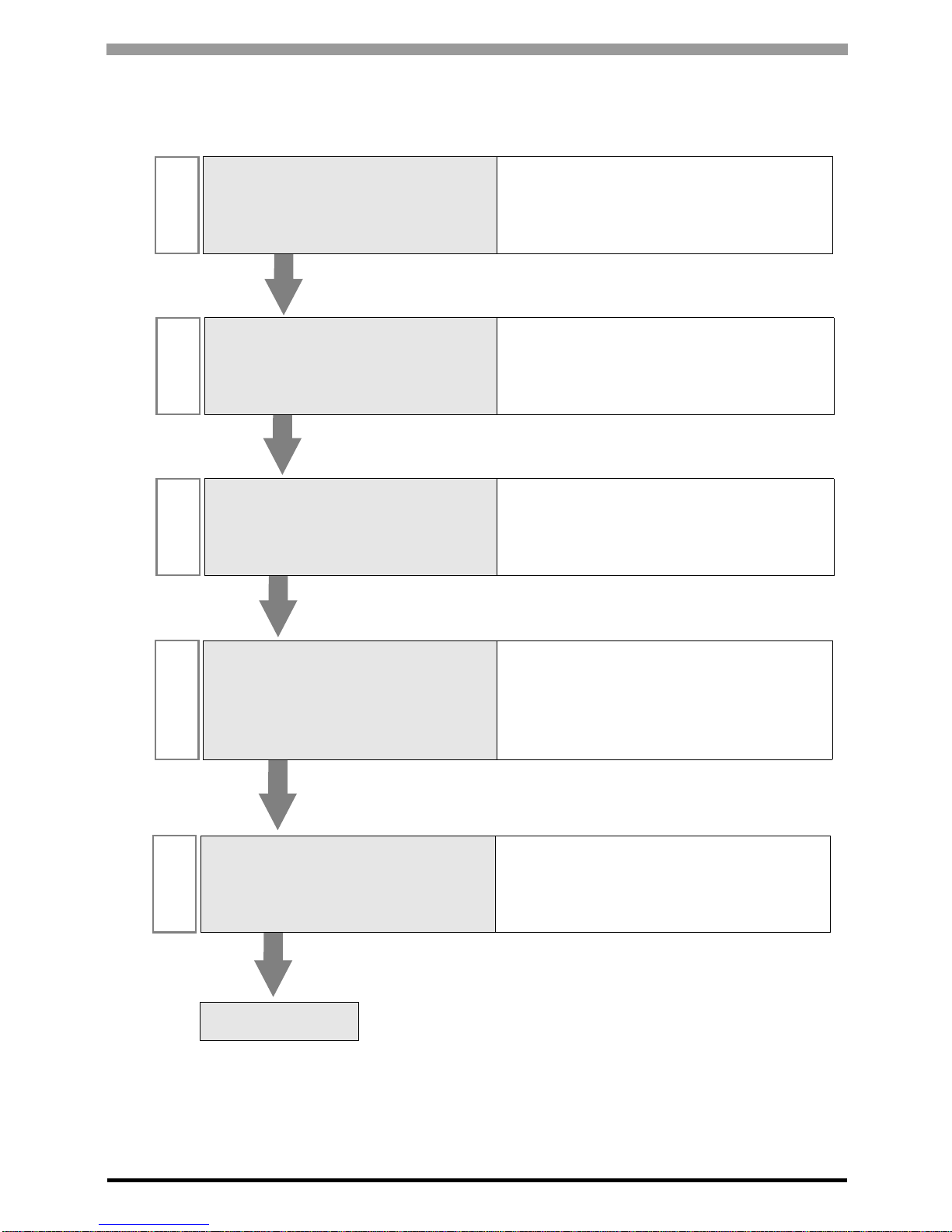
In this manual, the connection procedure will be described by following the below sections:
1
System Configuration
This section shows the types of External
Devices which can be connected and SIO
type.
)"1 System Configuration" (page 3)
2
Selection of External Device
Select a model (series) of the External
Device to be connected and connection
method.
)"2 Selection of External Device" (page 7)
3
Example of Communication Settings
This section shows setting examples for
communicating between the Display and
the External Device.
)"3 Example of Communication Setting"
(page 8)
4
Setup Items
This section describes communication
setup items on the Display.
Set communication settings of the Display
with GP-Pro Ex or in offline mode.
)"4 Setup Items" (page 24)
5
Cable Diagram
This section shows cables and adapters
for connecting the Display and the
External Device.
)"5 Cable Diagram" (page 29)
Operation
Page 3
MICREX-F Series SIO Driver
GP-Pro EX Device/PLC Connection Manual
3
1 System Configuration
The system configuration in the case when the External Device of Fu ji Electric Co.,Ltd. and the Display are
connected is shown.
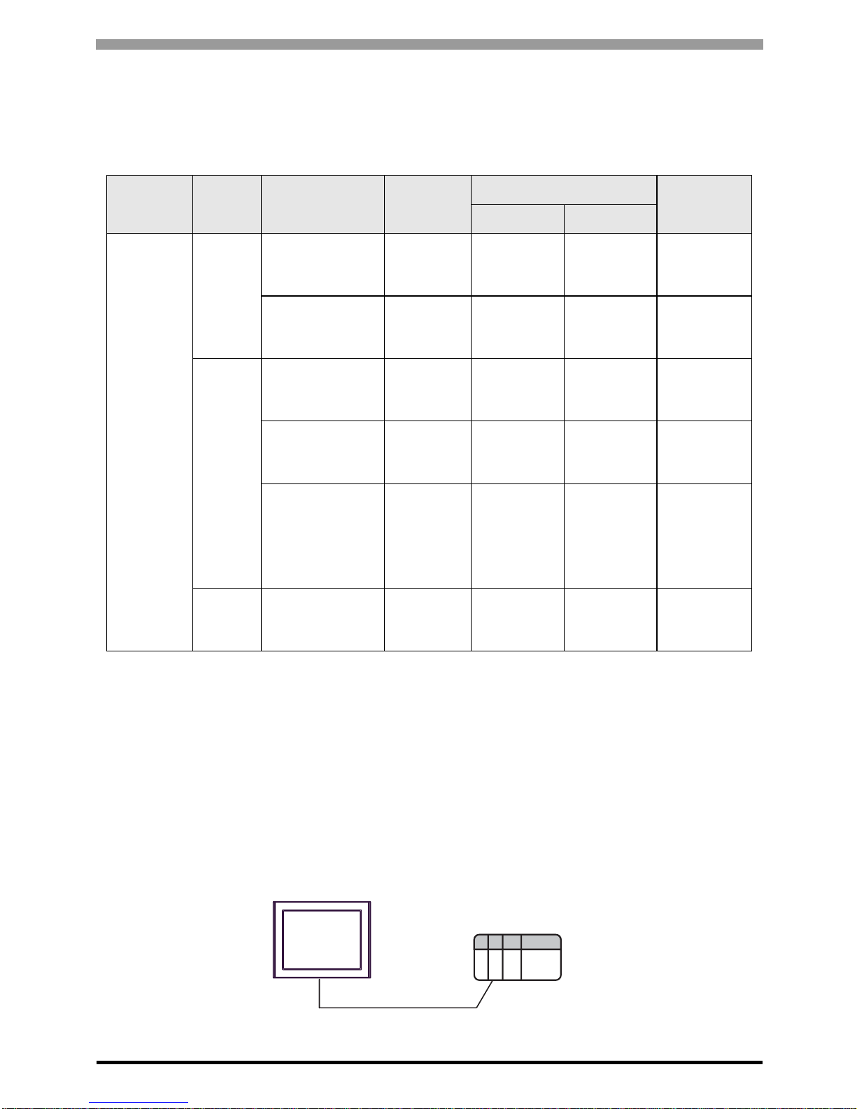
Connection Configuration
RS232C
• 1:1 Connection
Series CPU Link I/F SIO Type
Setting Example
Cable
Diagram
File Switch
MICREX-F
F80H
F120H
F250
RS232C interface
on FFU120B
RS232C
Setting
Example 1
(page 8)
Setting
Example 2
(page 11)
Cable
Diagram 1
(page 29)
RS485 interface
on FFU120B
RS422/485
(4wire)
Setting
Example 3
(page 13)
Setting
Example 4
(page 16)
Cable
Diagram 2
(page 32)
F30
*1
F50
*1
F60
F70
F70S
F80
F80H
F81
F120
F120H
F120S
F200
F250
*1 When you use F30 or F50 for T link connection, T link master adaptor (FTM050A) is necessary.
RS232C interface
on FFK120A-C10
RS232C
Setting
Example 1
(page 8)
Setting
Example 5
(page 18)
Cable
Diagram 1
(page 29)
RS485 interface
on FFK120A-C10
RS422/485
(4wire)
Setting
Example 3
(page 13)
Setting
Example 6
(page 20)
Cable
Diagram 2
(page 32)
FFK100A-C10
*2
*2 You cannot use FFK100A-C10 or NC1L-RS2 in 1:n configuration.
RS232C ---
Setting
Example 7
(page 22)
Cable
Diagram 3
(page 42)
F70
F70S
NC1L-RS2
*2 *3
*3 When you install 2 link units on the extension base unit created by T link function based on the basic base
unit of the External Device, you can connect the Display on either of 2 link units (simultaneous connection
on both 2 link units are not available). When you install 2 basic base units, simultaneous connection on both
2 link units are available.
RS232C
Setting
Example 1
(page 8)
Setting
Example 2
(page 11)
Cable
Diagram 4
(page 43)
External Device
RS232C
Display
Operation mode:1
Page 4
MICREX-F Series SIO Driver
GP-Pro EX Device/PLC Connection Manual
4
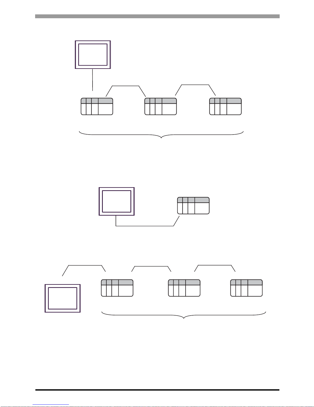
• 1:n Connection
* Turn ON the termination resistance switch on the interface which terminates the RS422 connection.
RS422/485 (4wire)
• 1:1 Connection
* Turn ON the termination resistance switch on the External Devi ce in te rface.
• 1:n Connection
* Turn ON the termination resistance switch on the interface which terminates the RS422 connection.
RS232 C
External Device*
External Device
External Device*
RS422/485 (4wire)
Operation mode:2
Operation mode:3
Operation mode:3
Max 16 units
Display
RS422/485 (4wire)
External Device*
Operation mode:
3
RS422/485 (4wire)
Display
Operation mode:3
Operation mode:
3
Operation mode:3
Max 16 units
RS422/485 (4wire)
Display
RS422/485 (4wire)
RS422/485 (4wire)
External Device External Device External Device*
Page 5
MICREX-F Series SIO Driver
GP-Pro EX Device/PLC Connection Manual
5
IPC COM Port
When connecting IPC with an External Device, the COM port used depends on the series and SIO type. Please
refer to the IPC manual for details.
Usable port
DIP Switch setting: RS-232C
Series
Usable Port
RS-232C RS-422/485(4 wire) RS-422/485(2 wire)
PS-2000B
COM1
*1
, COM2,
COM3
*1
, COM4
*1 The RI/5V can be switched. Use the IPC’s switch to change if necessary.
--
PS-3450A, PS-3451A,
PS3000-BA, PS3001-BD
COM1, COM2
*1*2
COM2
*1*2
COM2
*1*2
PS-3650A (T41 model),
PS-3651A (T41 model)
COM1
*1
--
PS-3650A (T42 model),
PS-3651A (T42 model)
COM1
*1*2
, COM2 COM1
*1*2
COM1
*1*2
PS-3700A (Pentium®4-M)
PS-3710A
COM1*1, COM2*1,
COM3*2, COM4
*2 Set up the SIO type with the DIP Switch. Please set up as follows according to SIO type to be used.
COM3
*2
COM3
*2
PS-3711A COM1*1, COM2
*2
COM2
*2
COM2
*2
PS4000
*3
*3 When making communication between an External Device and COM port on the Expansion slot,
only RS-232C is supported. However, ER (DTR/CTS) control cannot be executed because of the
specification of COM port.
For connection with External Device, use user-created cables and disable Pin Nos. 1, 4, 6 and 9.
Please refer to the IPC manual for details of pin layout.
COM1, COM2 - -
PL3000
COM1
*1*2
, COM2*1,
COM3, COM4
COM1
*1*2
COM1
*1*2
DIP Switch Setting Description
1OFF
*1
*1 When using PS-3450A, PS-3451A, PS3000-BA and PS3001-BD, turn ON the set value.
Reserved (always OFF)
2OFF
SIO type: RS-232C
3OFF
4 OFF Output mode of SD (TXD) data: Always output
5 OFF Terminal resistance (220Ω) insertion to SD (TXD): None
6 OFF Terminal resistance (220Ω) insertion to RD (RXD): None
7 OFF Short-circuit of SDA (TXA) and RDA (RXA): Not available
8 OFF Short-circuit of SDB (TXB) and RDB (RXB): Not available
9OFF
RS (RTS) Auto control mode: Disabled
10 OFF
Page 6
MICREX-F Series SIO Driver
GP-Pro EX Device/PLC Connection Manual
6
DIP Switch setting: RS-422/485 (4 wire)
DIP Switch setting: RS-422/485 (2 wire)
DIP Switch Setting Description
1 OFF Reserved (always OFF)
2ON
SIO type: RS-422/485
3ON
4 OFF Output mode of SD (TXD) data: Always output
5 OFF Terminal resistance (220Ω) insertion to SD (TXD): None
6 OFF Terminal resistance (220Ω) insertion to RD (RXD): None
7 OFF Short-circuit of SDA (TXA) and RDA (RXA): Not available
8 OFF Short-circuit of SDB (TXB) and RDB (RXB): Not available
9OFF
RS (RTS) Auto control mode: Disabled
10 OFF
DIP Switch Setting Description
1 OFF Reserved (always OFF)
2ON
SIO type: RS-422/485
3ON
4 OFF Output mode of SD (TXD) data: Always output
5 OFF Terminal resistance (220Ω) insertion to SD (TXD): None
6 OFF Terminal resistance (220Ω) insertion to RD (RXD): None
7 ON Short-circuit of SDA (TXA) and RDA (RXA): Available
8 ON Short-circuit of SDB (TXB) and RDB (RXB): Available
9ON
RS (RTS) Auto control mode: Enabled
10 ON
Page 7
MICREX-F Series SIO Driver
GP-Pro EX Device/PLC Connection Manual
7
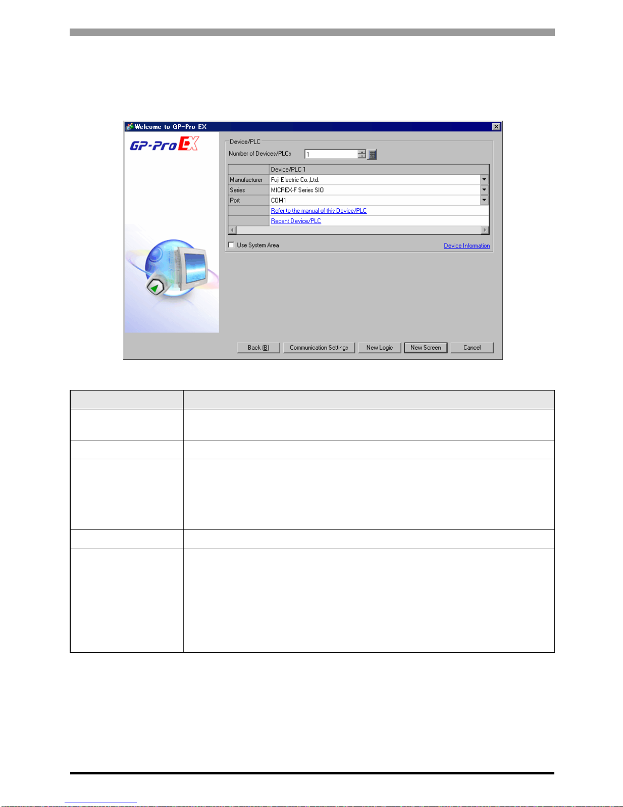
2 Selection of External Device
Select the External Device to be connected to the Display.
Setup Items Setup Description
Number of Devices/
PLCs
Enter an integer from 1 to 4 to define the number of Devices/PLCs to connect to the
display.
Manufacturer Sele ct the manufacturer of the External Device to connect. Select "Fuji Electric Co.,Ltd.".
Series
Select the External Device model (series) and the connection method. Select "MICREX-F
Series SIO".
In System configuration, make sure the External Device you are connecting is supported by
"MICREX-F Series SIO".
)"1 System Configuration" (page 3)
Port Select the Display port to be connected to the External Device.
Use System Area
Check this option to synchronize the system data area of the Display and the device
(memory) of the External Device. When synchronized, you can use the External Device’s
ladder program to switch the display or display the window on the Display.
Cf. GP-Pro EX Reference Manual "LS Area (Direct Access Method Ar ea )"
This feature can also be set in GP-Pro EX or in the Display's offline mode.
Cf. GP-Pro EX Reference Manual "System Settings [D i s pla y Uni t] - [S yste m
Area] Settings Guide"
Cf. Maintenance/Troubleshooting Guide "Main Unit - System Area Settings"
Page 8
MICREX-F Series SIO Driver
GP-Pro EX Device/PLC Connection Manual
8
3 Example of Communication Setting
Examples of communication settings of the Display and the External Device, recommended by Pro-face, are
shown.
When you use the MICREX-F Series, use GP-Pro EX and the ladder software to set as below.
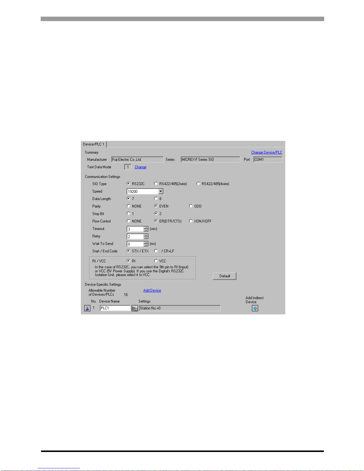
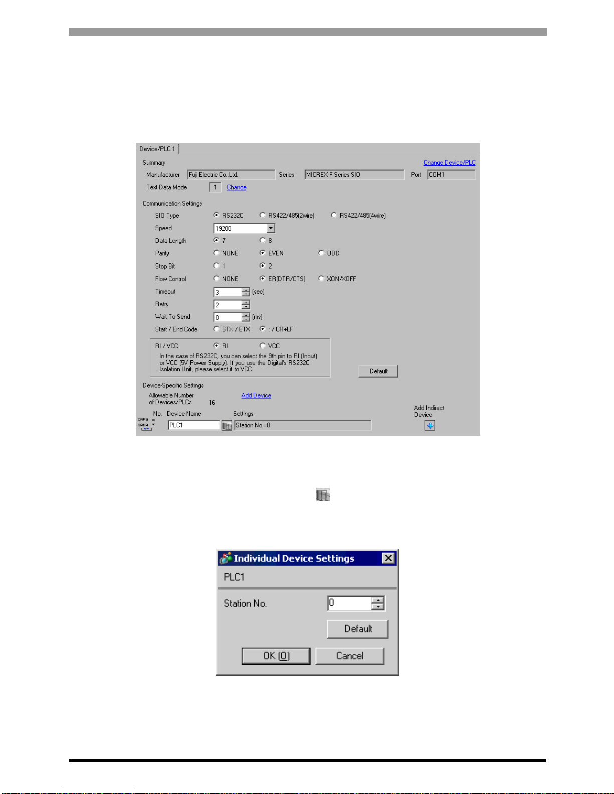
3.1 Setting Example 1
Settings of GP-Pro EX
Communication Settings
T o display the setup screen, from the [Project] menu, point to [System Settings] and select [Device/PLC].
Page 9
MICREX-F Series SIO Driver
GP-Pro EX Device/PLC Connection Manual
9
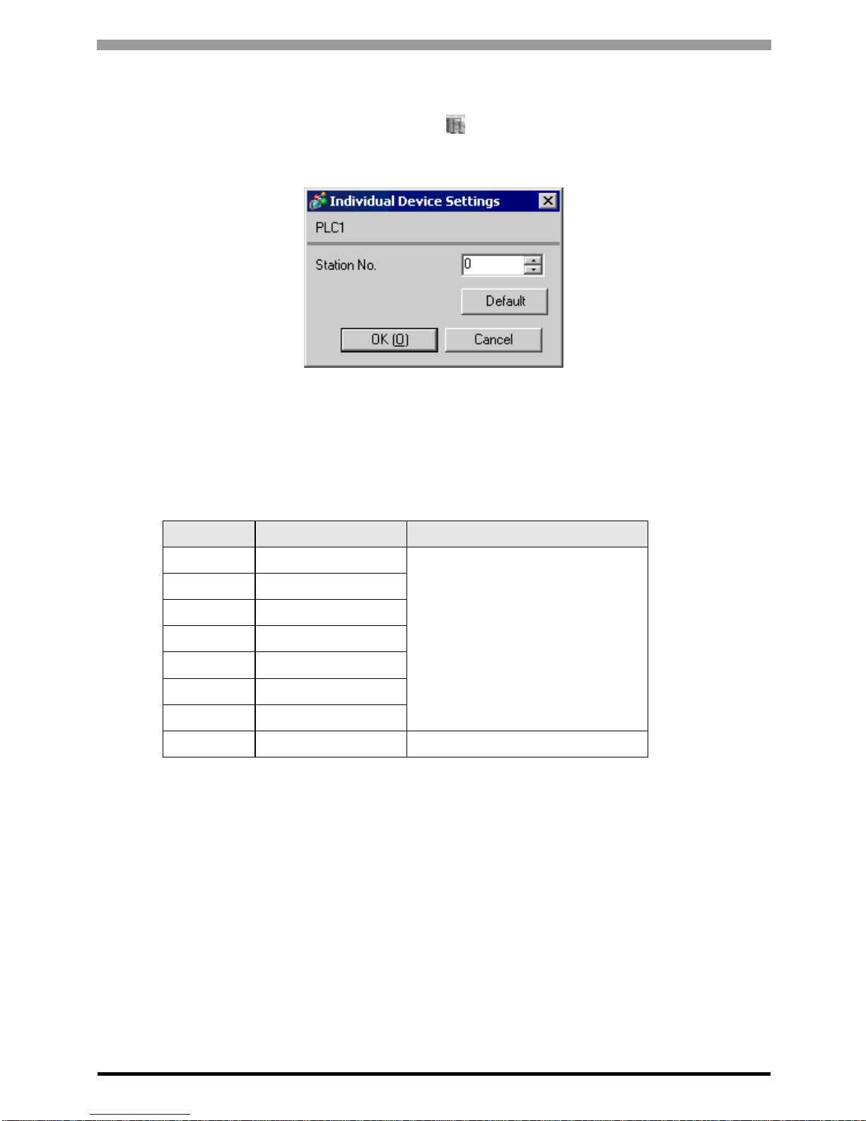
Device Setting
To display the [Individual Device Settings] dialog box, from [Device-Specific Settings] in the [Device/PLC]
window, select the external device and click [Settings] .
To connect multiple External Devices, from [Device-Specific Settings] in the [Device/PLC] window, click [Add
Device] to add another External Device.
Setting of External Device
(1) Turn OFF the DIP switch No.8 "Initialization method" on the rear panel of general-purpose interface module
of the External Device. Other settings are not necessary. The DIP switch setting will be effective after restart.
Use the rotary switch for MODE setting.
(2) Set the mode switch key of the External Device body to [TERM].
(3) Startup the ladder software. Execute [New File] from the [File] menu.
(4) Select the model of the External Device to use.
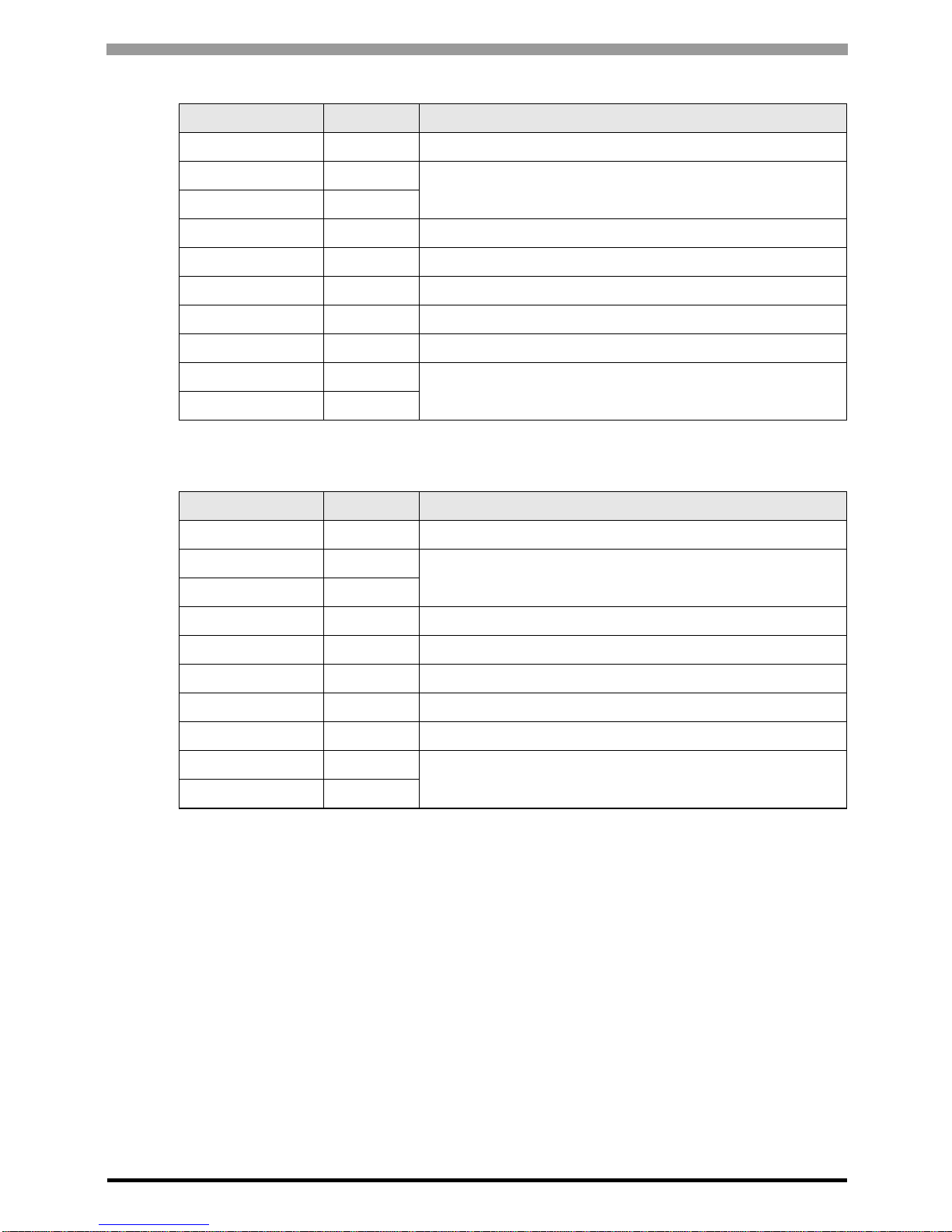
No. Setup Items Setup Description
1 No need
Unused
2 No need
3 No need
4 No need
5 No need
6 No need
7 No need
8OFF Initial file setting effective
Page 10
MICREX-F Series SIO Driver
GP-Pro EX Device/PLC Connection Manual
10
(5) Create the default file in the data table. Please refer to the manual of the External Device for the default file
number or the setting method. When you select MODE2 or 3, use the rotary switch to specify the same
number as the station No. in the device setting. The setting is not necessary for MODE1 (RS232C 1:1
connection). Please refer to the connection configuration diagrams for more details.
(6) Select [Transfer] from the [File] menu to transfer to the External Device body.
(7) After the transfer is completed, restart the External De vic e.
Setup Items Setup Description Notes
MODE switch Depending on connection type
Set by the rotary switch
Station No. Depending on connection type
Transmission Procedure No procedure
Set by the initial file
Mode Settings
Baud rate 19200
Data Bit 7
Parity Bit Even
Stop Bit 2
DCE/DTE DCE
CTS/RTS Always ON
DSR/DTR Always ON
Send Condition None
PK Access Enable
Transmission Code JIS
Code Conversion Enable
Head Code STX
End Code ETX
Head Code 1, 2 0
End Code 1, 2 0
BCC None
Page 11
MICREX-F Series SIO Driver
GP-Pro EX Device/PLC Connection Manual
11
3.2 Setting Example 2
Settings of GP-Pro EX
Communication Settings
T o display the setup screen, from the [Project] menu, point to [System Settings] and select [Device/PLC].
Device Setting
To display the [Individual Device Settings] dialog box, from [Device-Specific Settings] in the [Device/PLC]
window, select the external device and click [Settings] .
To connect multiple External Devices, from [Device-Specific Settings] in the [Device/PLC] window, click [Add
Device] to add another External Device.
Page 12
MICREX-F Series SIO Driver
GP-Pro EX Device/PLC Connection Manual
12
Setting of External Device
Turn ON the DIP switch No.8 "Initi alizatio n method" on the rear panel of general-purpos e interfa ce module of the
External Device. When you perform the settings with the switch, the head code, end code and send condition will
be fixed. Use the rotary switch for MODE setting. When you select MODE2 or 3, use the rotary switch to specify
the same number as the station No. in the device setting. The setting is not necessary for MODE1 (RS232C 1:1
connection). Please refer to the connection configuration diagrams for more details.
No. Setup Items Setup Description
1OFF
Baud rate = 192002ON
3ON
4OFF Stop bit length = 2
5ON Data bit length = 7
6ON Parity bit = Even
7ON Parity bit = Enable
8ON Switch setting ef fective
Setup Items Setup Description Notes
MODE switch
Depending on
connection type
Set by the rotary switch
Station No.
Depending on
connection type
Send Condition None
FixedHead Code :
End Code CR/LF
Page 13
MICREX-F Series SIO Driver
GP-Pro EX Device/PLC Connection Manual
13
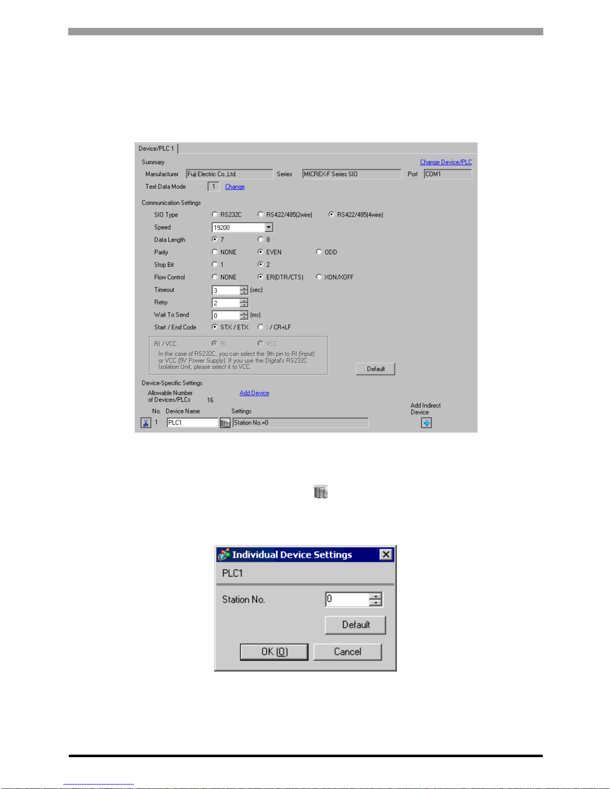
3.3 Setting Example 3
Settings of GP-Pro EX
Communication Settings
T o display the setup screen, from the [Project] menu, point to [System Settings] and select [Device/PLC].
Device Setting
To display the [Individual Device Settings] dialog box, from [Device-Specific Settings] in the [Device/PLC]
window, select the external device and click [Settings] .
To connect multiple External Devices, from [Device-Specific Settings] in the [Device/PLC] window, click [Add
Device] to add another External Device.
Page 14
MICREX-F Series SIO Driver
GP-Pro EX Device/PLC Connection Manual
14
Setting of External Device
(1) Turn OFF the DIP switch No.8 "Initialization method" on the rear panel of general-purpose interface module
of the External Device. Other settings are not necessary. The DIP switch setting will be effective after restart.
Use the rotary switch for MODE setting.
(2) Set the mode switch key of the External Device body to [TERM].
(3) Startup the ladder software. Execute [New File] from the [File] menu.
(4) Select the model of the External Device to use.
No. Setup Items Setup Description
1 No need
Unused
2 No need
3 No need
4 No need
5 No need
6 No need
7 No need
8OFF Initial file setting effective
Page 15
MICREX-F Series SIO Driver
GP-Pro EX Device/PLC Connection Manual
15
(5) Create the default file in the data table. Please refer to the manual of the External Device for the default file
number or the setting method.
Use the rotary switch to specify the same number as the station No. in the device setting. Please refer to the
connection configuration diagrams for more details.
(6) Select [Transfer] from the [File] menu to transfer to the External Device body.
(7) After the transfer is completed, restart the External De vic e.
Setup Items Setup Description Notes
MODE switch 3
Set by the rotary switch
Station No. Depending on connection type
Transmission Procedure No procedure
Set by the initial file
Mode Settings
Baud rate 19200
Data Bit 7
Parity Bit Even
Stop Bit 2
DCE/DTE DCE
CTS/RTS Always ON
DSR/DTR Always ON
Send Condition None
PK Access Enable
Transmission Code JIS
Code Conversion Enable
Head Code STX
End Code ETX
Head Code 1, 2 0
End Code 1, 2 0
BCC None
Page 16

MICREX-F Series SIO Driver
GP-Pro EX Device/PLC Connection Manual
16
3.4 Setting Example 4
Settings of GP-Pro EX
Communication Settings
T o display the setup screen, from the [Project] menu, point to [System Settings] and select [Device/PLC].
Device Setting
To display the [Individual Device Settings] dialog box, from [Device-Specific Settings] in the [Device/PLC]
window, select the external device and click [Settings] .
To connect multiple External Devices, from [Device-Specific Settings] in the [Device/PLC] window, click [Add
Device] to add another External Device.
Page 17

MICREX-F Series SIO Driver
GP-Pro EX Device/PLC Connection Manual
17
Setting of External Device
Turn ON the DIP switch No.8 "Initi alizatio n method" on the rear panel of general-purpos e interfa ce module of the
External Device. When you perform the settings with the switch, the head code, end code and send condition will
be fixed. Use the rotary switch for MODE setting. Use the rotary swi tch to spe cify the sa me number a s the statio n
No. in the device setting. Please refer to the connection configuration diagrams for more details.
No. Setup Items Setup Description
1OFF
Baud rate = 192002ON
3ON
4OFF Stop bit length = 2
5ON Data bit length = 7
6ON Parity bit = Even
7ON Parity bit = Enable
8ON Switch setting effective
Setup Items Setup Description Notes
MODE switch 3
Set by the rotary switch
Station No.
Depending on
connection type
Send Condition None
FixedHead Code :
End Code CR/LF
Page 18

MICREX-F Series SIO Driver
GP-Pro EX Device/PLC Connection Manual
18
3.5 Setting Example 5
Settings of GP-Pro EX
Communication Settings
T o display the setup screen, from the [Project] menu, point to [System Settings] and select [Device/PLC].
Device Setting
To display the [Individual Device Settings] dialog box, from [Device-Specific Settings] in the [Device/PLC]
window, select the external device and click [Settings] .
To connect multiple External Devices, from [Device-Specific Settings] in the [Device/PLC] window, click [Add
Device] to add another External Device.
Page 19

MICREX-F Series SIO Driver
GP-Pro EX Device/PLC Connection Manual
19
Setting of External Device
Turn ON the DIP switch No.8 "Initi alizatio n method" on the rear panel of general-purpos e interfa ce module of the
External Device. When you perform the settings with the switch, the head code, end code and send condition will
be fixed. Use the rotary switch for MODE setting. When you select MODE2 or 3, use the rotary switch to specify
the same number as the station No. in the device setting. The setting is not necessary for MODE1 (RS232C 1:1
connection). Please refer to the connection configuration diagrams for more details.
Settings of Character Configuration Switch
Baud Rate Setting Switch
No. Setup Items Setup Description
1OFF
Unused2OFF
3OFF
4OFF Stop bit length = 2
5ON Data bit length = 7
6ON Parity bit = Even
7ON Parity bit = Enable
8ON Switch setting effective
No. Setup Items Setup Description
1OFF
Always set to OFF.
2OFF
3OFF
4OFF
5OFF
6OFF
7ON Baud rate = 19200
8OFF Unused
Setup Items Setup Description Notes
MODE switch
Depending on
connection type
Set by the rotary switch
Station No.
Depending on
connection type
Send Condition None
FixedHead Code :
End Code CR/LF
Page 20

MICREX-F Series SIO Driver
GP-Pro EX Device/PLC Connection Manual
20
3.6 Setting Example 6
Settings of GP-Pro EX
Communication Settings
T o display the setup screen, from the [Project] menu, point to [System Settings] and select [Device/PLC].
Device Setting
To display the [Individual Device Settings] dialog box, from [Device-Specific Settings] in the [Device/PLC]
window, select the external device and click [Settings] .
To connect multiple External Devices, from [Device-Specific Settings] in the [Device/PLC] window, click [Add
Device] to add another External Device.
Page 21

MICREX-F Series SIO Driver
GP-Pro EX Device/PLC Connection Manual
21
Setting of External Device
Turn ON the DIP switch No.8 "Initi alizatio n method" on the rear panel of general-purpos e interfa ce module of the
External Device. When you perform the settings with the switch, the head code, end code and send condition will
be fixed. Use the rotary switch for MODE setting. Use the rotary swi tch to spe cify the sa me number a s the statio n
No. in the device setting. Please refer to the connection configuration diagrams for more details.
Settings of Character Configuration Switch
Baud Rate Setting Switch
No. Setup Items Setup Description
1OFF
Unused2OFF
3OFF
4OFF Stop bit length = 2
5ON Data bit length = 7
6ON Parity bit = Even
7ON Parity bit = Enable
8ON Switch setting effective
No. Setup Items Setup Description
1OFF
Always set to OFF.
2OFF
3OFF
4OFF
5OFF
6OFF
7ON Baud rate = 19200
8OFF Unused
Setup Items Setup Description Notes
MODE switch 3
Set by the rotary switch
Station No.
Depending on
connection type
Send Condition None
FixedHead Code :
End Code CR/LF
Page 22

MICREX-F Series SIO Driver
GP-Pro EX Device/PLC Connection Manual
22
3.7 Setting Example 7
Settings of GP-Pro EX
Communication Settings
T o display the setup screen, from the [Project] menu, point to [System Settings] and select [Device/PLC].
Device Setting
To display the [Individual Device Settings] dialog box, from [Device-Specific Settings] in the [Device/PLC]
window, select the external device and click [Settings] .
To connect multiple External Devices, from [Device-Specific Settings] in the [Device/PLC] window, click [Add
Device] to add another External Device.
Page 23

MICREX-F Series SIO Driver
GP-Pro EX Device/PLC Connection Manual
23
Setting of External Device
Perform the communication settings of the External Device in the de fault file. Create the default file in the data
table. Please refer to the manual of the External Device for the default file number or the setting method.
Setup Items Setup Description Notes
Transmission Procedure No procedure
Set by the initial file
Mode Settings
Baud rate 9600
Data Bit 7
Parity Bit Even
Stop Bit 2
DCE/DTE DCE
CTS/RTS Always ON
DSR/DTR Always ON
Send Condition None
PK Access Disabled
Transmission Code JIS
Code Conversion Enable
Head Code STX
End Code ETX
BCC None
Position TEXT
Formula Sum
Code Transmission Code
Page 24

MICREX-F Series SIO Driver
GP-Pro EX Device/PLC Connection Manual
24
4 Setup Items
Set communication settings of the Display with GP-Pro EX or in offline mode of the Display.
The setting of each parameter must be identical to that of External Devic e.
)"3 Example of Communication Setting" (page 8)
4.1 Setup Items in GP-Pro EX
Communication Settings
T o display the setup screen, from the [Project] menu, point to [System Settings] and select [Device/PLC].
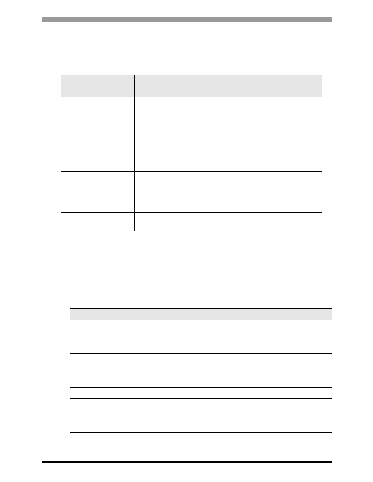
Setup Items Setup Description
SIO Type Select the SIO type to communicate with the External Device.
Speed Select speed between the External Device and the Display.
Data Length Select data length.
Parity Select how to check parity.
Stop Bit Select stop bit length.
Flow Control
Select the communication control method to prevent overflow of transmission and
reception data.
Timeout
Use an integer from 1 to 127 to enter the time (s) for which the Display waits for the
response from the External Device.
Retry
In case of no response from the External Device, use an integer from 0 to 255 to enter how
many times the Display retransmits the command .
Continues to the next page.
Page 25

MICREX-F Series SIO Driver
GP-Pro EX Device/PLC Connection Manual
25
Device Setting
To display the [Individual Device Settings] dialog box, from [Device-Specific Settings] in the [Device/PLC]
window, select the external device and click [Settings] .
To connect multiple External Devices, from [Device-Specific Settings] in the [Device/PLC] window, click [Add
Device] to add another External Device.
Wai t To Send
Use an integer from 0 to 255 to enter standby time (ms) for the Display from receiving
packets to transmitting next commands.
Start/End Code Select the start/end code for data.
RI/VCC
You can switch RI/VCC of the 9th pin when you select RS232C for SIO type.
It is necessary to change RI/5V by changeover switch of IPC when connect with IPC.
Please refer to the manual of the IPC for more detail.
• Refer to the GP-Pro EX Reference Manual for Indirect Device.
Cf. GP-Pro EX Reference Manual "Chan ging the Device/PLC at Runtime (Indirect
Device)"
Setup Items Setup Description
Station No. Enter a station number of the External Device, using 0 to 99.
Setup Items Setup Description
Page 26

MICREX-F Series SIO Driver
GP-Pro EX Device/PLC Connection Manual
26
4.2 Setup Items in Offline Mode
Communication Settings
T o display the setting screen, touch [Device/ PLC Settings] from [Peripheral Settings] in offline mode. Touch the
External Device you want to set from the displayed list.
• Refer to the Maintenance/Troubleshooting guide for information on how to enter offline mode or
about the operation.
Cf. Maintenance/Troubleshooting Guide "Offline Mode"
• The number of the setup items to be displayed for 1 page in the offline mode depends on the
Display in use. Please refer to the Reference manual for details.
Setup Items Setup Description
SIO Type
Select the SIO type to communicate with the External Device.
To make the communication settings correctly, confirm the serial interface specifications
of Display unit for [SIO Type].
We cannot guarantee the operation if a communication type that the serial interface does
not support is specified.
For details concerning the serial interface specifications, refer to the manual for Display
unit.
Speed Select speed between the External Device and the Display.
Data Length Select data length.
Parity Select how to check parity.
Stop Bit Select stop bit length.
Flow Control
Select the communication control method to prevent overflow of transmission and
reception data.
Continues to the next page.
Page 27

MICREX-F Series SIO Driver
GP-Pro EX Device/PLC Connection Manual
27
Device Setting
T o disp lay the setting screen, touch [D e vice/ PLC Se ttings] from [Periph era l Settings]. Touch the External Device
you want to set from the displayed list, and touch [Device].
Timeout (s)
Use an integer from 1 to 127 to enter the time (s) for which the Display waits for the
response from the External Device.
Retry
In case of no response from the External Device, use an integer from 0 to 255 to enter how
many times the Display retransmits the command .
Wait To Send (ms)
Use an integer from 0 to 255 to enter standby time (ms) for the Display from receiving
packets to transmitting next commands.
Start/End Code Select the start/end code for data.
Setup Items Setup Description
Device/PLC Name
Select the External Device for device setting. Device name is a title of External Device set
with GP-Pro EX.(Initial value [PLC1])
Station No. Enter a station number of the External Device, using 0 to 99.
Setup Items Setup Description
Page 28

MICREX-F Series SIO Driver
GP-Pro EX Device/PLC Connection Manual
28
Option
T o disp lay the setting screen, touch [D e vice/ PLC Se ttings] from [Periph era l Settings]. Touch the External Device
you want to set from the displayed list, and touch [Option].
Setup Items Setup Description
RI/VCC
Switch the 9th pin setting when you select RS232C for SIO type.
It is necessary to change RI/5V by changeover switch of IPC when connect with IPC.
Please refer to the manual of the IPC for more detail.
• GP-4*01TM do not have the [Option] setting in the offline mode.
Page 29

MICREX-F Series SIO Driver
GP-Pro EX Device/PLC Connection Manual
29
5 Cable Diagram
The cable diagram shown below may be different from the cable diagram recommended by Fuji Electric Co.,Ltd.
Please be assured there is no operational problem in applying the cable diagram shown in this manual.
• The FG pin of the External Device body must be D-class grounded. Please refer to the manual of the External
Device for more details.
• SG and FG are connected inside the Display. When connecting SG to the External Device, design the system
not to form short-circuit loop.
• Connect the isolation unit, when communication is not stabilized under the influence of a noise etc.
Cable Diagram 1
Display
(Connection Port)
Cable Notes
GP3000 (COM1)
GP4000
*1
(COM1)
ST (COM1)
LT3000 (COM1)
IPC
*2
PC/AT
*1 All GP4000 models except GP-4100 Series and GP-4203T
*2 Only the COM port which can communicate by RS-232C can be used.
) IPC COM Port (page 5)
1A
RS232C cable
by Pro-face
CA3-CBL232/5M-01 (5m)
For 1:1 connection, set the operation mode on
the interface to 1. For 1:n connection, set the
operation mode for the External Device
connected to the Display with RS232C to 2,
and for other Devices to 3.
1B Your own cable
Page 30

MICREX-F Series SIO Driver
GP-Pro EX Device/PLC Connection Manual
30
1A)
• 1:1 Connection
* Set the operation mode on the External Device interface to 1.
• 1:n connection
• Turn ON the termination resistance switch on the Ext erna l Devi ce which terminates the RS422
connection.
• For the 1st External Device connected with RS232C and RS422, set the operation mode on the
Link I/F to 2. For the following External Devices connected with RS422, set it to 3.
Display
CA3-CBL232/5M-01
RS232C
External Device*
Display
RS232 port on Link I/F
RS422 port on Link I/F
RS422 port on Link I/F
Your own cable (RS422 (4wire))
Shield
CA3-CBL232/5M-01
RS232C
Signal
name
RDA
RDB
SDA
SDB
SG
Signal
name
SDA
SDB
RDA
RDB
SG
FG
Page 31

MICREX-F Series SIO Driver
GP-Pro EX Device/PLC Connection Manual
31
1B)
• 1:1 Connection
* Set the operation mode on the External Device interface to 1.
• 1:n Connection
*1 Turn ON the termination resistance switch on the External Device which terminates the RS422 connection.
*2 Set the operation mode on the External Device interface to 2.
*3 Set the operation mode on the External Device interface to 3.
Display
D-sub 9 pin (socket)
D-sub 25 pin (plug)
External Device*
Shield
Pin
1
2
3
4
5
7
8
Signal
name
CD
RD
SD
ER
SG
RS
CS
Pin
1
2
3
4
5
6
7
8
20
Signal
name
FG
SD
RD
RTS
CTS
DSR
SG
CD
ER
D-sub 9 pin (socket)
D-sub 25 pin (plug)
External Device*1*3
Display
RS422 (4wire)
External Device*1*2
RS232 port on Link I/F
RS422 port on Link I/F
Shield
Shield
Pin
1
2
3
4
5
7
8
Signal
name
CD
RD
SD
ER
SG
RS
CS
Pin
1
2
3
4
5
6
7
8
20
Signal
name
FG
SD
RD
RTS
CTS
DSR
SG
CD
ER
Signal
name
RDA
RDB
SDA
SDB
SG
Signal
name
SDA
SDB
RDA
RDB
SG
FG
Page 32

MICREX-F Series SIO Driver
GP-Pro EX Device/PLC Connection Manual
32
Cable Diagram 2
Display
(Connection Port)
Cable Notes
GP3000
*1
(COM1)
AGP-3302B (COM2)
GP-4*01TM (COM1)
ST
*2
(COM2)
LT3000 (COM1)
IPC
*3
*1 All GP models except AGP-3302B
*2 All ST models except AST-3211A and AST-3302B
2A
RS422 cable by Pro-face
CA3-CBL422/5M-01 (5m)
Turn ON the
termination resistance
switch on the External
Device which
terminates the RS422
connection.
Set the operation
MODE
to 3.
2B
COM port conversion adapter by Pro-face
CA3-ADPCOM-01
+
Terminal block conversion adapter by Pro-face
CA3-ADPTRM-01
+
Your own cable
2C
COM port conversion adapter by Pro-face
CA3-ADPCOM-01
+
422 cable for GP by Pro-face
CA3-CBL422-01 (5m)
2D Your own cable
GP3000
*4
(COM2)
2E
Online adapter by Pro-face
CA4-ADPONL-01
+
Terminal block conversion adapter by Pro-face
CA3-ADPTRM-01
+
Your own cable
2F
Online adapter by Pro-face
CA4-ADPONL-01
+
422 cable by Pro-face
CA3-CBL422-01 (5m)
2G
Online adapter by Pro-face
CA4-ADPONL-01
+
Your own cable
GP4000
*5
(COM2)
GP-4201T (COM1)
2H
RS-422 T er minal Block Conversion Adapter by Pro-face
PFXZCBADTM1
*6
+
Your own cable
2A
RS422 cable by Pro-face
CA3-CBL422/5M-01 (5m)
2C
COM port conversion adapter by Pro-face
CA3-ADPCOM-01
+
422 cable for GP by Pro-face
CA3-CBL422-01 (5m)
2D Your own cable
Page 33

MICREX-F Series SIO Driver
GP-Pro EX Device/PLC Connection Manual
33
*3 Only the COM port which can communicate by RS-422/485 (4 wire) can be used.
) IPC COM Port (page 5)
*4 All GP models except GP-3200 series and AGP-3302B
*5 All GP4000 models except GP-4100 Series, GP-4*01TM, GP-4201T and GP-4*03T
*6 When using a Terminal Block Conversion Adapter (CA3-ADPTRM-01) instead of the RS-422 Terminal Block
Conversion Adapter, refer to Cable Diagram 2B.
Page 34

MICREX-F Series SIO Driver
GP-Pro EX Device/PLC Connection Manual
34
2A)
• 1:1 Connection
*Turn On the termination resistance switch of the External Device, and set the operation mode to 3.
• 1:n Connection
*1 Turn ON the termination resistance switch on the External Device which terminates the RS422 connection.
*2 Set the operation mode on the External Device interface to 3.
External Device*
Display
Signal name
RDA
RDB
SDA
SDB
SG
FG
CA3-CBL422/5M-01
Signal name
SDA
SDB
RDA
RDB
SG
FG
CA3-CBL 422/5M-01
External Device*1*2
External Device*2
Display
Shield
Signal name
RDA
RDB
SDA
SDB
SG
FG
Signal name
SDA
SDB
RDA
RDB
SG
FG
Signal name
SDA
SDB
RDA
RDB
SG
FG
Page 35

MICREX-F Series SIO Driver
GP-Pro EX Device/PLC Connection Manual
35
2B)
• 1:1 Connection
* Turn On the termination resistance switch of the External Device, and set the operation mode to 3.
• 1:n Connection
*1 Turn ON the termination resistance switch on the External Device which terminates the RS422 connection.
*2 Set the operation mode on the External Device interface to 3.
External Device*
Display
Your own cable
Terminal block
Shield
CA3-ADPTRM-01
CA3-ADPCOM-01
Signal name
RDA
RDB
SDA
SDB
TERM
SG
Signal name
SDA
SDB
RDA
RDB
SG
FG
External Device*2
External Device*1*2
Display
Your own cable
Terminal block
Shield
Shield
Signal name
RDA
RDB
SDA
SDB
TERM
SG
Signal name
SDA
SDB
RDA
RDB
SG
FG
Signal name
SDA
SDB
RDA
RDB
SG
FG
CA3-ADPTRM-01
CA3-ADPCOM-01
Page 36

MICREX-F Series SIO Driver
GP-Pro EX Device/PLC Connection Manual
36
2C)
• 1:1 Connection
Do not connect the FG terminal of CA3-CBL422-01 to the External Device.
* Turn On the termination resi stance switch of the External Device, and set the operation mode to 3.
• 1:n Connection
Do not connect the FG terminal of CA3-CBL422-01 to the External Device.
*1 Turn ON the termination resistance switch on the External Device which terminates the RS422 connection.
*2 Set the operation mode on the External Device interface to 3.
External Device*
Display
CA3-CBL422-01
CA3-ADPCOM-01
Signal name
RDA
RDB
SDA
SDB
SG
Signal name
SDA
SDB
RDA
RDB
SG
External Device*2
External Device*1*2
Display
Shield
Signal name
RDA
RDB
SDA
SDB
SG
Signal name
SDA
SDB
RDA
RDB
SG
CA3-CBL422-01
CA3-ADPCOM-01
Signal name
SDA
SDB
RDA
RDB
SG
FG
Page 37

MICREX-F Series SIO Driver
GP-Pro EX Device/PLC Connection Manual
37
2D)
• 1:1 Connection
* Turn On the termination resistance switch of the External Device, and set the operation mode to 3.
1:n Connection
*1 Turn ON the termination resistance switch on the External Device which terminates the RS422 connection.
*2 Set the operation mode on the External Device interface to 3.
External Device*
D-sub 9 pin (socket)
Termination
resistance
100 1W
Display
Shield
Signal
name
RDA
RDB
SDA
SDB
SG
ERA
CSA
ERB
CSB
Signal
name
SDA
SDB
RDA
RDB
SG
FG
Pin
1
2
3
7
5
4
8
9
6
External Device*2 External Device*1*2
D-sub 9 pin (socket)
Termination
resistance
100 1W
Display
Shield Shield
Signal
name
RDA
RDB
SDA
SDB
SG
ERA
CSA
ERB
CSB
Pin
1
2
3
7
5
4
8
9
6
Signal
name
SDA
SDB
RDA
RDB
SG
FG
Signal
name
SDA
SDB
RDA
RDB
SG
FG
Page 38

MICREX-F Series SIO Driver
GP-Pro EX Device/PLC Connection Manual
38
2E)
• 1:1 Connection
* Turn On the termination resistance switch of the External Device, and set the operation mode to 3.
• 1:n Connection
*1 Turn ON the termination resistance switch on the External Device which terminates the RS422 connection.
*2 Set the operation mode on the External Device interface to 3.
External Device*
Display
Shield
Terminal block
Your own cable
Signal name
RDA
RDB
SDA
SDB
TERM
SG
CA3-ADPTRM-01
CA4-ADPONL-01
Signal name
SDA
SDB
RDA
RDB
SG
FG
External Device*2 External Device*1*2
Display
Your own cable
Terminal block
Shield
Shield
Signal name
RDA
RDB
SDA
SDB
TERM
SG
Signal name
SDA
SDB
RDA
RDB
SG
FG
Signal name
SDA
SDB
RDA
RDB
SG
FG
CA3-ADPTRM-01
CA4-ADPONL-01
Page 39

MICREX-F Series SIO Driver
GP-Pro EX Device/PLC Connection Manual
39
2F)
• 1:1 Connection
Do not connect the FG terminal of CA3-CBL422-01 to the External Device.
* Turn On the termination resistance switch of the External Device, and set the operation mode to 3.
• 1:n Connection
Do not connect the FG terminal of CA3-CBL422-01 to the External Device.
*1 Turn ON the termination resistance switch on the External Device which terminates the RS422 connection.
*2 Set the operation mode on the External Device interface to 3.
External Device*
Display
CA3-CBL422-01
CA4-ADPONL-01
Signal name
RDA
RDB
SDA
SDB
SG
Signal name
SDA
SDB
RDA
RDB
SG
Display
External Device*2 External Device*1*2
Signal name
RDA
RDB
SDA
SDB
SG
Signal name
SDA
SDB
RDA
RDB
SG
Signal name
SDA
SDB
RDA
RDB
SG
FG
CA3-CBL422-01
CA4-ADPONL-01
Page 40

MICREX-F Series SIO Driver
GP-Pro EX Device/PLC Connection Manual
40
2G)
• 1:1 Connection
* Turn On the termination resistance switch of the External Device, and set the operation mode to 3.
1:n Connection
*1 Turn ON the termination resistance switch on the External Device which terminates the RS422 connection.
*2 Set the operation mode on the External Device interface to 3.
External Device*
Display
D-sub 9 pin (plug)
Shield
CA4-ADPONL-01
Pin
2
7
3
8
5
1
Signal name
RDA
RDB
SDA
SDB
SG
TERMRX
Signal name
SDA
SDB
RDA
RDB
SG
FG
External Device*2
External Device*1*2
D-sub 9 pin (plug)
Display
Shield
Shield
Pin
2
7
3
8
5
1
Signal name
RDA
RDB
SDA
SDB
SG
TERMRX
Signal name
SDA
SDB
RDA
RDB
SG
FG
Signal name
SDA
SDB
RDA
RDB
SG
FG
CA4-ADPONL-01
Page 41

MICREX-F Series SIO Driver
GP-Pro EX Device/PLC Connection Manual
41
2H)
• 1:1 Connection
* Turn On the termination resistance switch of the External Device, and set the operation mode to 3.
• 1:n Connection
*1 Turn ON the termination resistance switch on the External Device which terminates the RS422 connection.
*2 Set the operation mode on the External Device interface to 3.
External Device*
Display
Your own cable
Terminal block
Shield
PFXZCBADTM1
Signal name
RDA
RDB
SDA
SDB
TERM
SG
Signal name
SDA
SDB
RDA
RDB
SG
FG
External Device*2
External Device*1*2
Display
Your own cable
Terminal block
Shield
Shield
Signal name
RDA
RDB
SDA
SDB
TERM
SG
Signal name
SDA
SDB
RDA
RDB
SG
FG
Signal name
SDA
SDB
RDA
RDB
SG
FG
PFXZCBADTM1
Page 42

MICREX-F Series SIO Driver
GP-Pro EX Device/PLC Connection Manual
42
Cable Diagram 3
3A)
* Set the operation mode on the External Device interface to 1.
Display
(Connection Port)
Cable Notes
GP3000 (COM1)
GP4000
*1
(COM1)
ST (COM1)
LT3000 (COM1)
IPC
*2
PC/AT
*1 All GP4000 models except GP-4100 Series and GP-4203T
*2 Only the COM port which can communicate by RS-232C can be used.
) IPC COM Port (page 5)
3A Your own cable
D-sub 9 pin (socket)
External Device*
Display
Shield
Pin
2
3
4
5
7
8
Signal
name
RD
SD
ER
SG
RS
CS
Signal
name
FG
SD
RD
CTS
DSR
SG
CD
ER
Pin
B1
B2
B3
B5
B6
B7
B8
A4
Page 43

MICREX-F Series SIO Driver
GP-Pro EX Device/PLC Connection Manual
43
Cable Diagram 4
4A)
* Set the operation mode on the External Device interface to 1.
4B)
* Set the operation mode on the External Device interface to 1.
Display
(Connection Port)
Cable Notes
GP3000 (COM1)
GP4000
*1
(COM1)
ST (COM1)
LT3000 (COM1)
IPC
*2
PC/AT
*1 All GP4000 models except GP-4100 Series and GP-4203T
*2 Only the COM port which can communicate by RS-232C can be used.
IPC COM Port (page 5)
4A
RS232C cable by Pro-face
CA3-CBL232/5M-01 (5m)
Set the operation mode
on the interface to 1.
4B Your own cable
Display
External Device*
CA3-CBL232/5M-01
RS232C
Display
D-sub 9 pin (socket)
D-sub 25 pin (plug)
External Device*
Shield
Pin
1
2
3
4
5
7
8
Signal
name
CD
RD
SD
ER
SG
RS
CS
Signal
name
FG
SD
RD
RTS
CTS
DSR
SG
CD
ER
Pin
1
2
3
4
5
6
7
8
20
Page 44

MICREX-F Series SIO Driver
GP-Pro EX Device/PLC Connection Manual
44
6 Supported Device
Range of supported device address is shown in the table below. Please note that the actually supported range of
the devices varies depending on the External Device to be used. Please check the act u al range in the manual of
your connecting equipment.
This address can be specified as system data area.
Device Bit Address Word Address 32bits Notes
Input Relay B00000 - B0511F WB0000 - WB0511
*1
Direct I/O --- W24.0000 - W24.0159
Auxiliary Relay M00000 - M0511F WM0000 - WM0511
*1
Keep Relay K 00000 - K0063F WK0000 - WK0063
*1
Differential Relay D00000 - D0063F WD0000 - WD0063
*1*2
Link Relay L00000 - L0511F WL0000 - WL0511
*1
Special Relay F00000 - F4095F WF0000 - WF4095
*1*2
Announce Relay A00000 - A4095F WA0000 - WA4095
*1*2
Timer 0.01 sec. T0000 - T0511 --Timer 0.1 sec. T0512 - T1023 --Counter C0000 - C0255 --Timer 0.01 sec. (Current Value) --- TR0000 - TR0511
Timer 0.01 sec. (Setting Value) --- TS0000 - TS0511
Timer 0.1 sec. (Current Value) --- W9.0000 - W9.0511
Counter (Current Value) --- CR0000 - CR0255
Counter (Setting Value) --- CS0000 - CS0255
Data Memory
--- BD0000 - BD4095
--- DI0000 - DI4095
--- SI0000 - SI4095
File Memory
--- W30.0000 - W30.4094
*3
--- W31.0000 - W31.4094
*3
--- W32.0000 - W32.4094
*3
--- W33.0000 - W33.4094
*4
--- W34.0000 - W34.4094
*4
Page 45

MICREX-F Series SIO Driver
GP-Pro EX Device/PLC Connection Manual
45
*1 The highest bit in the word device corresponds to the bit 0 in the bit device. The lowest bit in the word device
corresponds to the bit F in the bit device.
<Example> When writing Hex data "0001" in the address WB0002 (word device)
*2 Write disable
*3 Always use in 16-bit data by user definition.
*4 Always use in 32-bit data by user definition.
B002* (bit device) 0 1 2 3 4 5 6 7 8 9 A B C D E F
WB0002 (word device) 0000000000000001
• Please refer to the GP-Pro EX Reference Manual for system data area.
Cf. "GP-Pro EX Reference Manual "LS Area (Direct Access Method Area)"
• Please refer to the precautions on manual notation for icons in the table.
)"Manual Symbols and Terminology"
Page 46

MICREX-F Series SIO Driver
GP-Pro EX Device/PLC Connection Manual
46
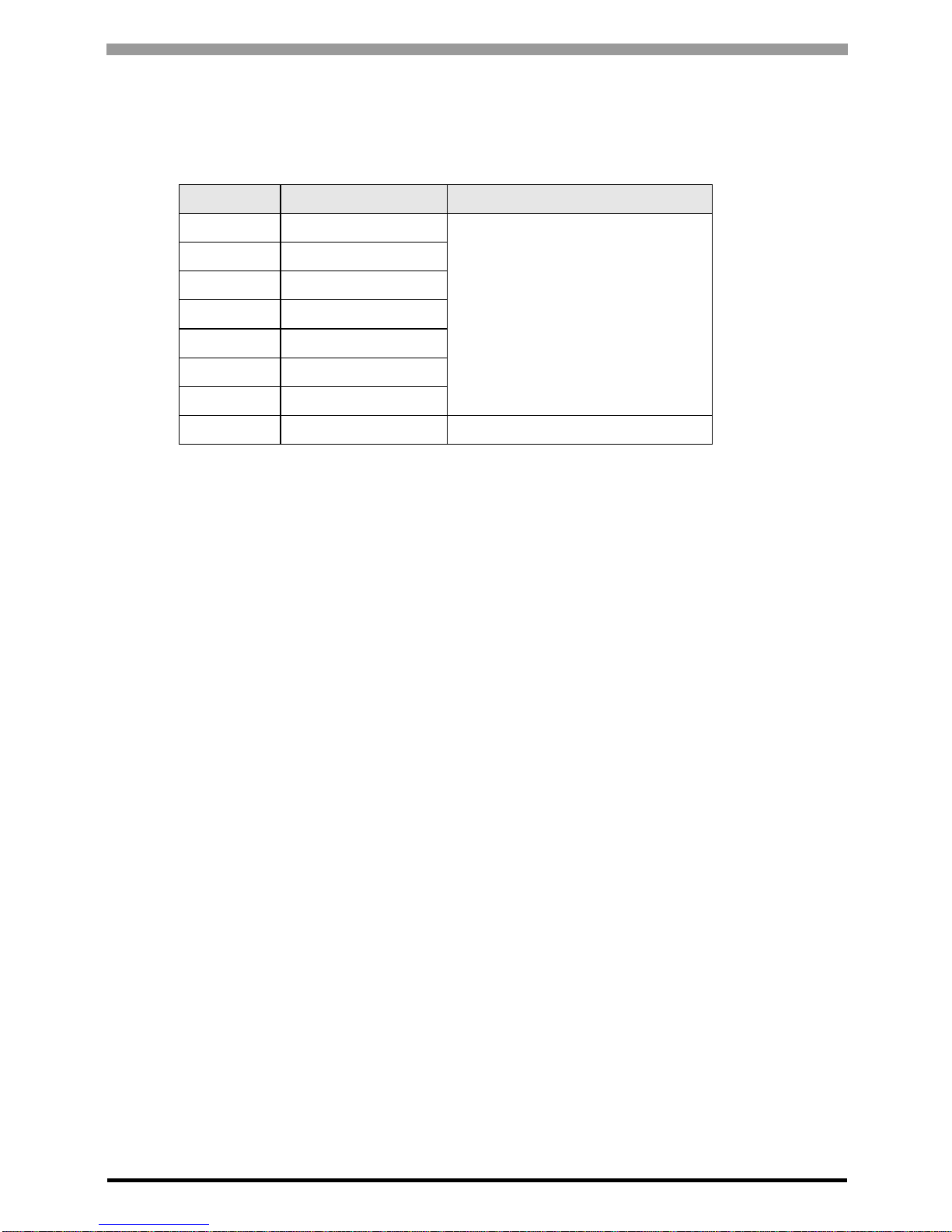
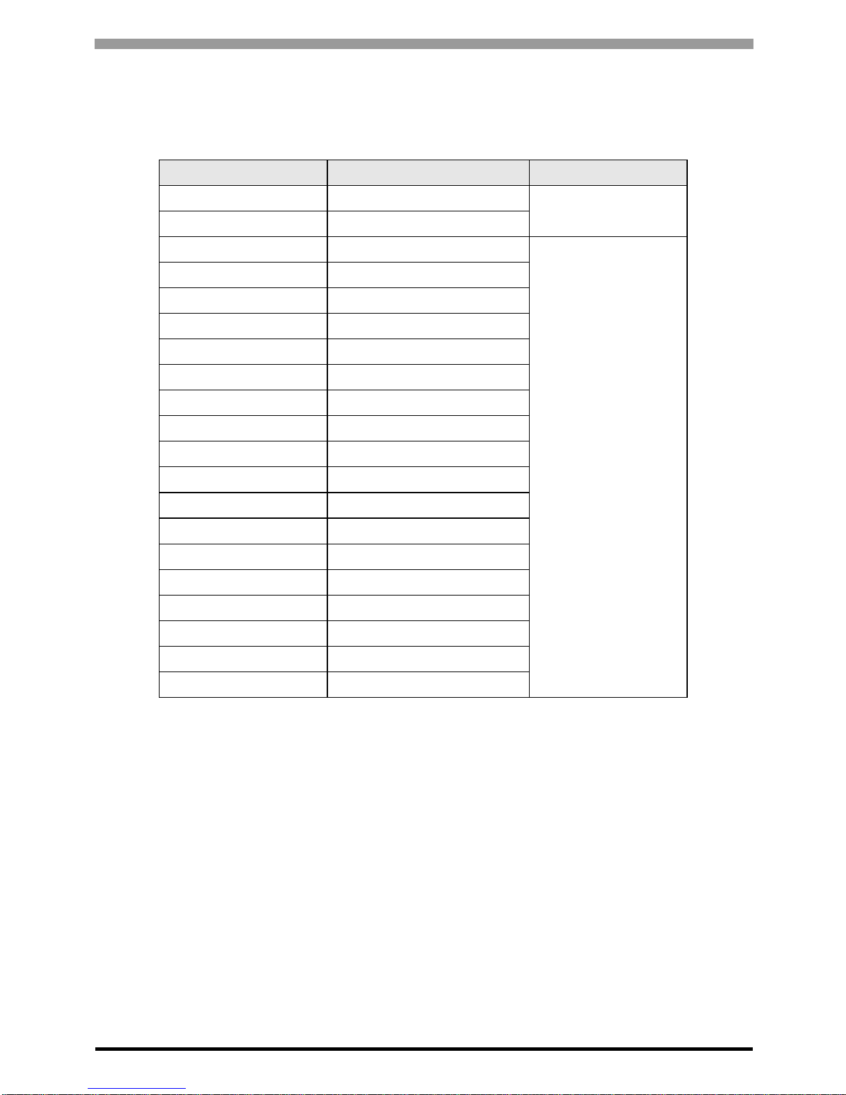
7 Device Code and Address Code
Use device code and address code when you select "Device Type & Address" for the address type in data
displays.
Device Device Name
Device Code
(HEX)
Address Code
Input Relay B 0080 Word Address
Direct I/O W24. 0015 Word Address
Auxiliary Relay M 0081 Word Address
Keep Relay K 0084 Word Address
Differential Relay D 0083 Word Address
Link Relay L 0088 W ord Address
Special Relay F 0082 Word Address
Announce Relay A 0085 Word Address
Timer 0.01 sec. (Current Value) TR 0062 W ord Address
Timer 0.01 sec. (Setting Value) TS 0065 Word Address
Timer 0.1 sec. (Current Value) W9. 0063 Word Address
Counter (Current Value) CR 0061 Word Address
Counter (Setting Value) CS 0064 Word Address
Data Memory
BD 0000 Word Address
DI 0001 Word Address
SI 0002 Word Address
File Memory
W30. 0010 Word Address
W31. 0011 Word Address
W32. 0012 Word Address
W33. 0013 Word Address
W34. 0014 Word Address
Page 47

MICREX-F Series SIO Driver
GP-Pro EX Device/PLC Connection Manual
47
8 Error Messages
Error messages are displayed on the screen of Display as follows: "No. : Device Name: Error Message (Error
Occurrence Area)". Each description is shown below.
Display Examples of Error Messages
"RHAA035: PLC1: Error has been responded for device write command (Error Code: 2 [02H])"
Item Description
No. Error No.
Device Name
Name of External Device where error occurs. Device name is a titl e of External Device set
with GP-Pro EX. (Initial value [PLC1])
Error Message Displays messages related to the error which occurs.
Error Occurrence Area
Displays IP address or device address of External Device where error occurs, or error codes
received from External Device.
• IP address is displayed such as "IP address(Decimal): MAC address( Hex)".
• Device address is diplayed such as "Address: Device address".
• Received error codes are displayed such as "Decimal[Hex]".
• Refer to your External Device manual for details on received error codes.
• Refer to "Display-related errors" in "Maintenance/Troubleshooting Guide" for details on the error
messages common to the driver.
Page 48

MICREX-F Series SIO Driver
GP-Pro EX Device/PLC Connection Manual
48
 Loading...