

Page 1
MANIFOLDS
DATASHEET
The FUJI FCX-AII differential, gauge and absolute
pressure transmitters can be direct mounted with
different kinds of manifold, adapted for the application and the type of transmitter.
The manifolds can be delivered mounted on the
transmitters or supplied separately.
When supplied mounted, the complete assembly is
fully pressure tested, and calibrated in the factory.
Technical information
Material :
Standard : Stainless steel 316 for manifold body and
valves.
Carbon steel : for quantities of 50 or more (consult
Fuji).
Upon request : body material in Monel,
Duplex,Hastelloy C 276, etc.
Bolts material : stainless steel 316.
Gasket : PTFE (standard), Grafoil etc...
Bolting size :
M10 for static pressure 160 bar max. and gauge pressure for 100 bar max.
M12 and 7/16 - 20 UNF for 420 bar static and 500 bar
gauge pressure.
W
Code symbols
1 2 3 4
W
*2
2
3
5
6
*4
7
8
*5
9
*1
Type
1 Valve - type 1318CDADABAA-FU - SS 316L
2 Valves - type 2166CDAHHBAA -FU - SS 316L
3 Valves - type 3152CDAHHBAA-FU - SS 316L
3 Valves - type 3050CDAHHBAA-FU - SS 316L
5 Valves - type 5050CDAHHBAA-FU - SS 316L
3 Valves - type Flange/Flange 3454CHHHHBAA-FU - SS 316L
2 Valves - type 2052CDADABAA-FU - SS 316L
Bolting size & material
7/16 - 20 UNF - Carbon steel
0
7/16 - 20 UNF - SS 316
1
M10 - SS 316
2
M12 - SS 316
3
None
4
Mounted on transmitter
*3
2
Yes
1
No - Separate kit
Notes :
1 : For 420 bar static pressure (differential pressure), and 500
bar (gauge pressure), M10 bolting is not suitable, please
select 7/16 or M12.
2 : No bolting is necessary for this manifold type.
3 : When manifold is ordered mounted on the transmitter,
hydrostatic pressure test and calibration are made with
manifold, so complete set is tested.
4 : Manifold type 3050 is low cost version of type 3152.
5 : Supplied with fitting if connection 1/2" NPT Female
Manifolds
Mounting :
Manifold can be mounted on the transmitter.
All tests and manufacturing operations will be done
with the manifold mounted :
- Pressure test (leakage test) at 1,5 x static pressure
for differential pressure transmitter at overpressure
rating for gauge and absolute pressure transmitters.
- Calibration with factory facilities.
Process connection :
1/2” NPT female, others upon request.
Operating pressure :
The maximum pressure is 414 bar (6000 PSI).
Upon request, manifolds for maximum pressure 690
bar (10000 PSI) can be delivered.
Fuji Electric France S.A.S.
EDS5-F04
DATE
b
January 2017
Page 2
W
Robinet
d’isolation
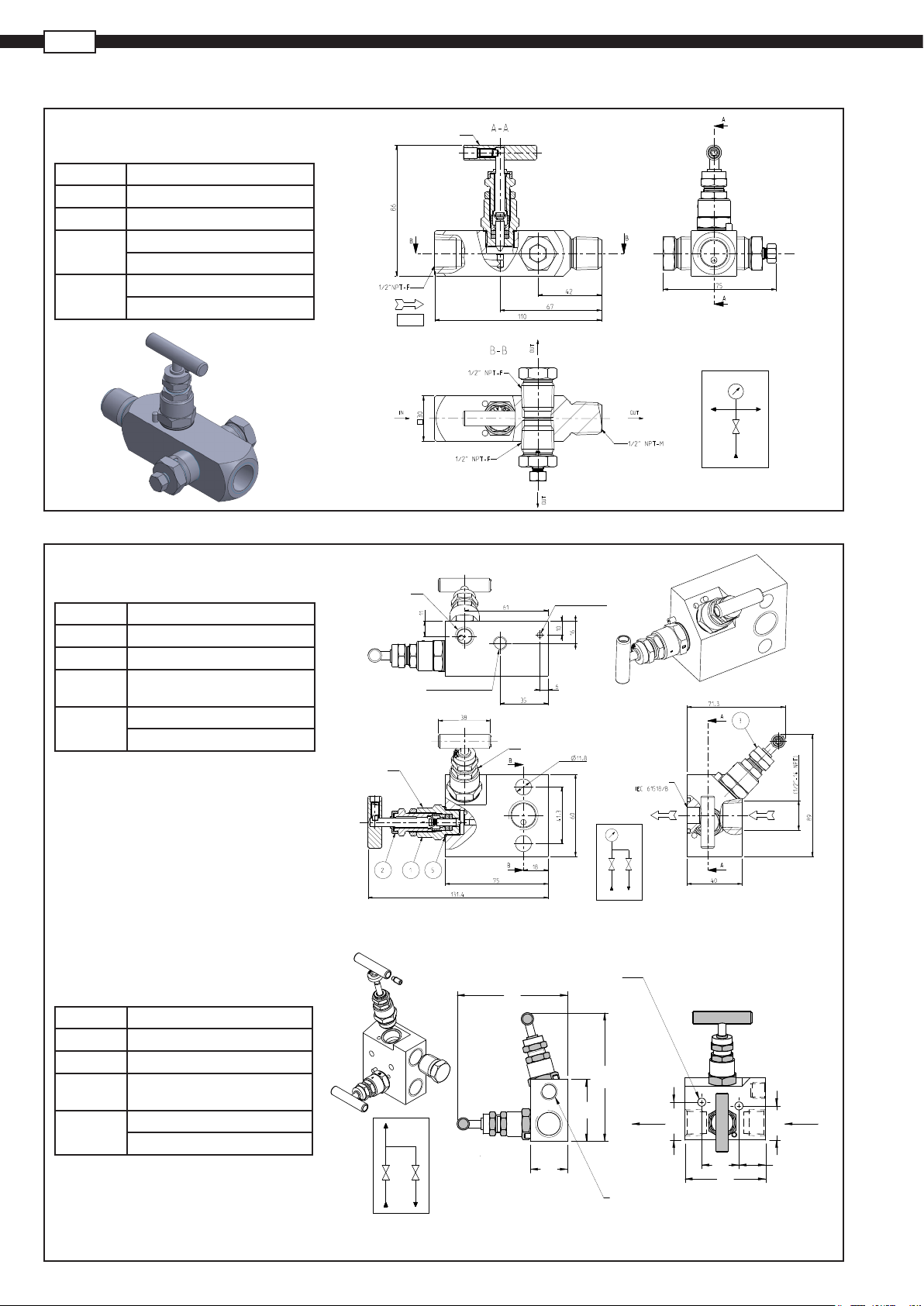
OUTLINE DIMENSIONS (unit : mm)
1 valve manifold
Type 1318CDADABAA - FU
Pressure 414 bar (6000 Psi)
Material SS 316L
Sealing PTFE
Connection
Various
1 INLET - 1/2“ NPT female
1 OUTLET - 1/2“ NPTmale
Bleeder - 1/2“ NPT
Cap - 1/2“ NPT
2 valves manifold
Type 2166CDAHHBAA - FU
Pressure 414 bar (6000 Psi)
Material SS 316L
Sealing PTFE
Connection
Various
1 INLET - 1/2“ NPT female
Drain - 1/4“NPT
Fixing holes - M10
Isolate valve
(OPEN)
PURGE
1/4” NPT-F
FLOW
Trou de fixation
Ø10
Robinet
de purge
Trou de fixation
Ø4
(Ouvert)
2 valves manifold
Type 2052CDADABAA - FU
Pressure 414 bar (6000 Psi)
Material SS 316L
Sealing PTFE
Connection
Various
1 INLET - 1/2“ NPT female
Drain / Cap - 1/4“NPT
Fixing holes - Ø6,5
(Ouvert)
2 - Fixing holes Ø6,5
89
ISOLATE
Côté instrument
VENT.
ENTREE
(Ouvert)
SORTIE
.
T
N
E
V
103
50
OUTLET
30.5
30
30
65
INLET
27.5
21.5
DRAIN 1/4" NPT-F
2
Page 3

3 valves manifold
Type 3050CDAHHBAA - FU
Pressure 414 bar (6000 Psi)
Material SS 316L
Sealing PTFE
Connection INLET - 1/2“ NPT female
Process
connection
Divers Fixing holes - M10 / Ø12
Various mounting
124
Fixing holes
M10
214
E
QU
A
L
I
S
EQUALISE
ISOLATE
41.4
30
Ø12
ISOLATE
D
P
OUTLET
70
35
E
INLET
32
54
96
INLET INLET
3 valves manifold
Type 3152CDAHHBAA - FU
Pressure 414 bar (6000 Psi)
Material SS 316L
Sealing PTFE
Connection INLET - 1/2“ NPT femelle
Process
Direct mounting
connection
Various DRAIN - 1/4“ NPT
3 valves manifold
Type 3454CHHHHBAA - FU
Pressure 414 bar (6000 Psi)
Material SS 316L
Sealing PTFE
Connection INLET - 1/2“ NPT female
Process
connection
Various DRAIN / CAPS 1/4“ NPT
FLANGE/FLANGE direct
mounting
Isolating
valve
162
54
ISOLATE EQUALISE ISOLATE
DRAIN 1/4" NPT-F
Fixing holes
Fixing holes
Ø 12
124
41.4
21
30
82
110
142
Isolating
valve
Isolating
valve
(open)
D
P
DRAIN DRAIN
INLET INLET
OUTLET
I
S
OL
A
T
E
70
INLET
32
FLOW
(Drain)
3
Page 4

W
Mail : sales.dpt@fujielectric.fr - web : www.fujielectric.fr
5 valves manifold
Type 5050CDAHHBAA - FU
10.5
16
Pressure 414 bar (6000 Psi)
Material SS 316L
Sealing PTFE
Connection INLET - 1/2“ NPT female
Process
Direct mounting
connection
Various
Drain - 1/4“ NPT
Fixation holes - M10 / Ø12
D
P
30
102
260
VENT. EQUALISE VENT.
124
ISOLATE
Ø 12
54
142
41.4
ISOLATE
DRAIN 1/4" NPT
Fixing hole
M10
INLET INLET
OUTLET
DRAINDRAIN
Ø 25.5
V
E
N
T
.
70
2
INLET
32
Fuji Electric France S.A.S.
46 rue Georges Besse - ZI du brézet - 63039 Clermont ferrand
Tél : 04 73 98 26 98 - Fax : 04 73 98 26 99
Fuji Electric can accept no responsibility for possible errors in catalogues, brochures and other printed material. Fuji Electric reserves the right to alter its
products without notice. This also applies to products already on order provided that such alterations can be made without subsequential changes being
necessary in specifications already agreed. All trademarks in this material are property of the respective companies. All rights reseved.
 Loading...