

Fuji Electric MA-E1-0.75, MA-E1-3.7 Installation Manual
- 1 -
Installation Manual
Panel-mount Adapter "MA-E1"
Thank you for purchasing this panel-mount adapter "MA-E1." This adapter allows you to install your FRENIC-Multi to the panel of your
system by making use of the mounting holes used for your conventional inverter (FVR-E11S-2, 0.75 kW or below or 3.7 kW;
FVR-E11S-4, 3.7 kW; and FVR-E11S-7, 0.4 kW or below or 2.2 kW).
(The FVR-E11S-2, 1.5/2.2 kW and FVR-E11S-4, 0.4 to 2.2 kW can be replaced with the FRENIC-Multi series without this adapter.)
1. Check that:
(1) A panel-mount adapter is contained in the package.
(2) The panel-mount adapter is not damaged or dented during
transportation.
(3) The panel-mount adapter is the model you ordered. You may
check the model name (see the table below) printed on the
nameplate (shown at the right).
(4) For the model MA-E1-3.7, four screws (M4x12) are also
contained in the package.
If you suspect the product is not working properly or if you have
any questions about the product, contact your Fuji Electric
representative.
MA-E1-0.75 MA-E1-3.7
2. Panel-mount Adapter Models and Applicable Inverter Models
Applicable Inverter Models
Panel-mount Adapter Models
FRENIC-Multi series FVR-E11S series
FRN0.1E1S-2**
FRN0.2E1S-2**
FRN0.4E1S-2**
FRN0.75E1S-2**
FVR0.1E11S-2
FVR0.2E11S-2
FVR0.4E11S-2
FVR0.75E11S-2
MA-E1-0.75
FRN0.1E1S-7**
FRN0.2E1S-7**
FRN0.4E1S-7**
FVR0.1E11S-7
FVR0.2E11S-7
FVR0.4E11S-7
MA-E1-3.7
FRN3.7E1S-2**
FRN3.7E1S-4**
FRN2.2E1S-7**
FVR3.7E11S-2
FVR3.7E11S-4
FVR2.2E11S-7
Note 1: A box () in the above table replaces A, E, or J depending on shipping destination.
Note 2: Asterisks (**) in the above table replace alphanumerics which denote the following:
12: RS-485 communications card built-in type 1P: PG interface card built-in type
No number: Standard type
Nameplate
- 2 -
3. Installation Procedure
Four M4 screws are required to install a panel-mount adapter (1.2 mm thick) to the panel of your system. You should provide screws that
match the panel.
MA-E1-0.75
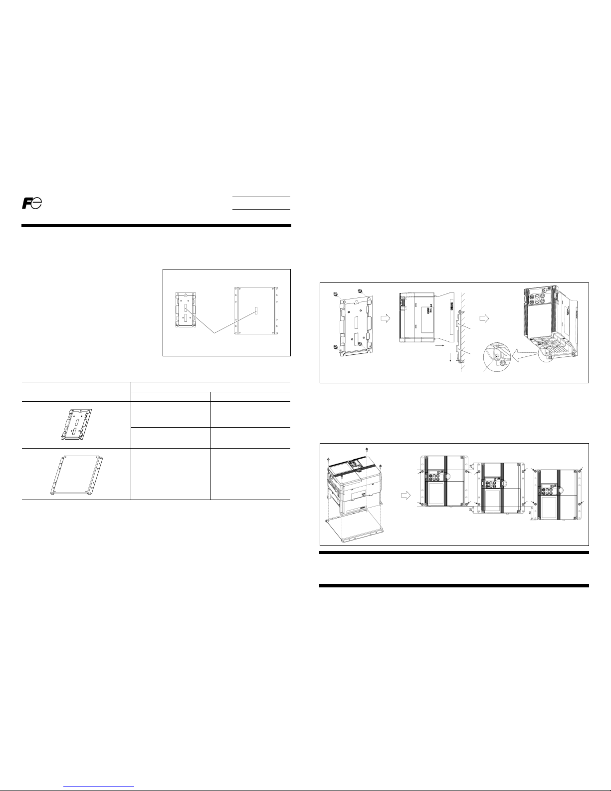
(1) Secure the panel-mount adapter to the panel with four M4 screws (to be provided by the customer).
When replacing the FVR-E11S series with the FRENIC-Multi series, out of the three holes provided in the upper end of the
panel-mount adapter, use the right and left holes. (The center hole is provided for replacement with other types of inverters.)
(2) Press your FRENIC-Multi against the panel-mount adapter so that the FRENIC-Multi's lower rear corners come to above the end of
lower tabs "B" of the panel-mount adapter and the cutout provided in the center of the inverter's rear side become fitted over upper
tabs "A."
(3) Slide down the FRENIC-Multi along the panel-mount adapter. Make sure that the holes provided in the lower rear corners of the
FRENIC-Multi are fitted over the bosses on the panel-mount adapter.
MA-E1-3.7
(1) Secure your FRENIC-Multi to the panel-mount adapter with four screws (M4x12) that come with the panel-mount adapter.
(Tightening torque: 1.8 N
·m)
(2) Secure the panel-mount adapter holding the FRENIC-Multi to the panel of your system with four M4 screws (to be provided by the
customer).
At each of the four corners of the panel-mount adapter are three mounting holes. Usually use the center holes. If using the center
holes cannot assure an extra space of 100 mm or more above or below the installed FRENIC-Multi, use the upper or lower holes,
respectively.
Fuji Electric FA Components & Systems Co., Ltd.
Mitsui Sumitomo Bank Ningyo-cho Bldg., 5-7, Nihonbashi, Odemma-cho, Chuo-ku, Tokyo, 103-0011, Japan
Phone: +81 3 5847 8011 Fax: +81 3 5847 8172
URL: http://www.fujielectric.co.jp/fcs/
INR-SI47-1105
A
B
Boss on the
panel-mount adapter
4 (M4x12) screws
(that come with the
panel-mount adapter) 4 (M4) screws
(to be provided by the customer)
4 (M4) screws
(to be provided by the customer)
(Lower mounting holes
are used.)
(Center mounting holes
are used.)
(Upper mounting holes
are used.)
 Loading...