

Page 1

Page 2

TABLE OF CONTENTS
Preface ............................................................................................................................................... 2
Product Overview ............................................................................................................................. 2
Safety Instructions ........................................................................................................................... 3
1. Introduction ............................................................................................................................... 6
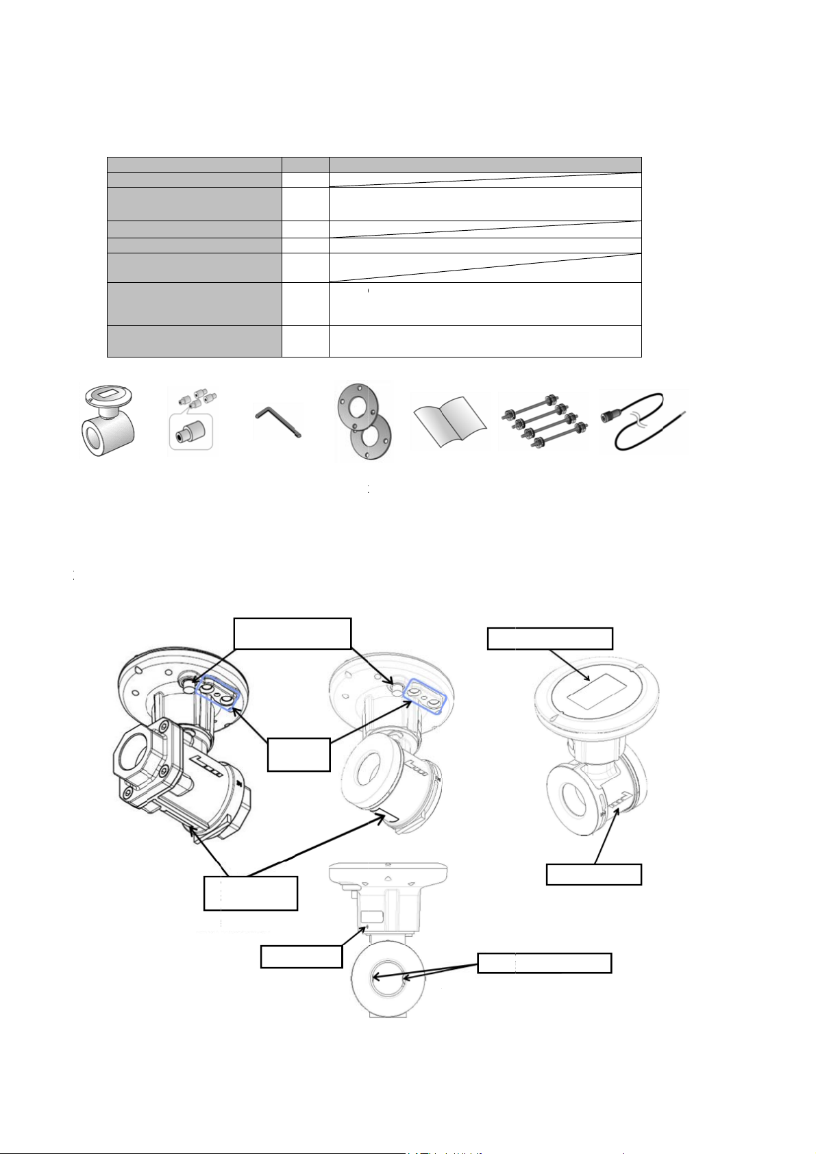
1-1. Scope of supply .............................................................................................................. 6
1-2. Name of each part ........................................................................................................... 6
2. Installation ................................................................................................................................. 7
3. Setting Up ................................................................................................................................ 12
3-1. Measurement and indication setting ........................................................................... 13
3-2. Output setting (for external power supply type) ........................................................ 14
4. Display ..................................................................................................................................... 16
4-1. Button operations ......................................................................................................... 16
4-2. Operation modes .......................................................................................................... 18
4-3. Setting items ................................................................................................................. 21
5. Wiring (External Power Supply Type) .................................................................................... 27
6. Operation ................................................................................................................................. 29
7. Alarm ........................................................................................................................................ 30
7-1. Aberration in flow measurement ................................................................................. 30
7-2. Aberrant pressure value ............................................................................................... 31
7-3. Aberrant temperature value .........................................................................................
7-4. Memory aberration ........................................................................................................ 32
8. Power Interruption (External Power Supply Type) ............................................................... 33
9. Battery Life (Built-In Battery Type) ........................................................................................ 34
10. Troubleshooting ...................................................................................................................... 35
11. Outline Diagram ...................................................................................................................... 37
Warranty and Maintenance ............................................................................................................ 38
31
1
Page 3

Preface
Thank you very much for purchasing the Ultrasonic Flow Meter for Air FWD this time. Please be sure
to read this Instruction Manual to use this product correctly and safely and to prevent failures.
Please arrange for operators who actually use this product to know the context of this Instruction
Manual surely. This Instruction Manual is necessary for performing maintenance, too. Please keep
the Manual until this product is disposed of.
Product Overview
This flow meter is the ultrasonic flow meter for air capable of measuring the flow of air at pressure
from the atmospheric pressure to less than 1 MPa. The flow meter is installed to pipes by screwing its
taper pipe threads to the pipes or by being tightened between pipe flanges.
Screw connection type (Taper pipe threads): FWD025, FWD032
Wafer connection type (Installation between pipe flanges and by tightening with bolts):
FWD040, FWD050, FWD065, FWD080
Flange connection type (JIS 10K flange): FWD100, FWD150, FWD200
2
Page 4
Safety Instructions
To ensure the safe use of this flow meter and to prevent a failure or an unexpected situation,
instructions to which attention must be paid are indicated with the following symbols.
Definitions
Danger
Warning
Note
General
Danger
Working environment and applicable fluid
Note
Incorrect handling by failure to follow instructions with this sign may lead to
imminent danger of death or serious injury.
Incorrect handling by failure to follow instructions with this sign may lead to death
or serious injury.
Incorrect handling by failure to follow instructions with this sign may lead to injury,
properties loss (product damage, etc.), pecuniary loss, and/or punishment
according to a penal regulation for violation of laws and ordinances.
This symbol indicates that improper operation may results in an accident.
This symbol indicates prohibited acts.
This symbol indicates matters you should observe without fail.
Do not use for applications that require safety, such as nuclear, railroad, aircraft,
vehicle, playground equipment, etc.
Do not modify the product.
Do not use the product for foods, drinks, medical chemicals, etc., because it is
not of sanitary specifications.
Do not use the product in the atmosphere of an inflammable gas, etc., because it
is not of explosion-proof specifications.
Do not apply any fluid other than air (compressed air used in factories) to this
flow meter. (The meter can be applied for nitrogen by factory setting before
shipment from our factory.)
Observe the temperature and humidity ranges (-10 to +60C and 90%RH or
lower) and pressure range (the atmospheric pressure to less than 1 MPa) in
use.
Avoid usage in an ambient containing a corrosive gas (chlorine, hydrogen
sulfide, etc.) and/or for an application to a fluid containing a corrosive gas.
This flow meter is not of a perfect waterproof structure (IP64). Do not install it at
a place that may be submerged in water.
Install the flow meter as far away from an electric noise source as possible. If it is
installed near the electric noise source, ground the shield of the external
connection cable.
The installation of a sunshade is recommended if the flow meter is exposed to
direct sunlight.
3
Page 5
Operation
Note
Storage
Note
Piping
Warning
Note
This flow meter is not a specified measuring instrument defined in Japanese
measurement law. The product cannot be used for billing transactions or
certification.
When opening a valve to start fluid flow, open the valve not all at once but
gradually. Opening of the valve all at once may cause a failure of the flow meter
if a pressure difference is occurring between the upstream side and
downstream side of the valve.
Store the flow meter at a place away from fire and not exposed to direct
sunlight.
Do not place any combustible material, inflammable substance and heating
body in the periphery of the flow meter.
Store this flow meter at a place which ambient temperature is -20 to +70C and
where no dew condensation occurs.
Do not ride on this flow meter using it as a foothold.
Do not hold the display section of this flow meter.
In the case that a flow-regulating valve, etc., that may cause turbulence of the
flow is installed, its location must be on the downstream side of the flow
meter.
In the case of new piping, install the product after sufficient cleaning of the
pipe(s).
Vertical piping is recommended when mist, dust, etc. are contained in a large
amount. In horizontal piping, install the flow meter in such a way that the
display section faces upward.
Do not install the product in locations where strong compressive force, tensile
force, or load may be applied after its installation.
Arrange piping so that the flow direction conforms to the direction of arrow
indicated on the flow meter’s body.
Do not drop it or do not make it bumped. Do not apply excessive impact,
either.
When rotating the display section, do not apply a force in a direction other
than the rotating direction.
Keep hands off the ultrasonic sensors.
4
Page 6
Wiring
Danger
Note
Disassembling and inspection
Note
Disposal
Warning
When performing wiring work, follow the instructions in this Manual.
Use the product within the rating.
Do not use the product on a voltage exceeding permissible load.
Do not place the product’s external connection cable together with or near to
power supply line(s) or power line(s), etc.
Electrical isolation of a remote counter (a receiver) from others is
recommended.
Do not apply an excessive tensile force to the external connection cable.
Ensure that the cable tip is not soaked in water during wiring work, etc.
When connecting the power supply wire of the external connection cable to an
external power supply, be careful not to short-circuit it. Use an external power
supply having a short-circuit protecting function.
Be sure to perform the wiring work in a state that power supply from the
external power supply is interrupted.
Do not perform operation and the wiring work with wet hands.
Do not disassemble this flow meter.
Presence of fluid flow makes a pilot lamp light up in a normal state. In the case
of no indication of the pilot lamp, contact our branch or sales office nearby.
If mist and dust is contained in a large amount, disconnect the flow meter
periodically to check for the presence of dirt etc., and remove it as necessary.
Be careful not to touch the ultrasonic sensors during inspection.
A lithium ion battery is incorporated in this flow meter. NEVER dispose of this
flow meter through general disposal routes. [Built-in battery type]
NEVER throw this flow meter into a fire. Otherwise, it may catch a fire or
explode. [Built-in battery type]
5
Page 7
1.
F
2
c
e
e
o
e
e
c
d
e
/
n
n
2
y
r
e
n
n
p
G
p
P
N
i
4
2
N
C
L
E
T
T
S
s
s
o
s
r
N
K
F
C
P
e
a
a
n
e
a
n
A
W
o
o
o
C
e
S
A
e
g
O
O
A
I
Introdu
1-
1. Scop
tion
of suppl
Upon deliv
LOW METER
Ultras
Cente
M4 h
Flang
Instru
(This
Bolt s
(Bolts
Exter
(exter
ry of the p
Name
nic flowmet
ring collars
xagonal wre
gasket
tion Manual
ocument)
t
nuts/plain wa
al connectio
al power su
CENTERIN
COLLARS
oduct, conf
r 1
ch 1
shes)
cable
ply type)
HEXAGO
WREN
rm that the
Q’ty
Acce
1
set
1
5 m o
1
See
Acce
The b
of req
Acce
AL
H
FLA
GAS
(WA
CONNE
TY
following it
about usage.
sory of the w
sory of the w
olts/nuts/plai
uired quantiti
sory of the w
r 20 m (Optio
GE
ETS
ER
TION
E)
OPE
M
ms are con
Remarks
fer connecti
fer connecti
washers are
s
fer connecti
)
RATION
NUAL
ained in th
n type
n type
put into a ba
n type
BOLT SET
(WAFER
ONNECTION
TYPE)
package:
in a set
EXTERN
CONNECT
CABLE
L
ON
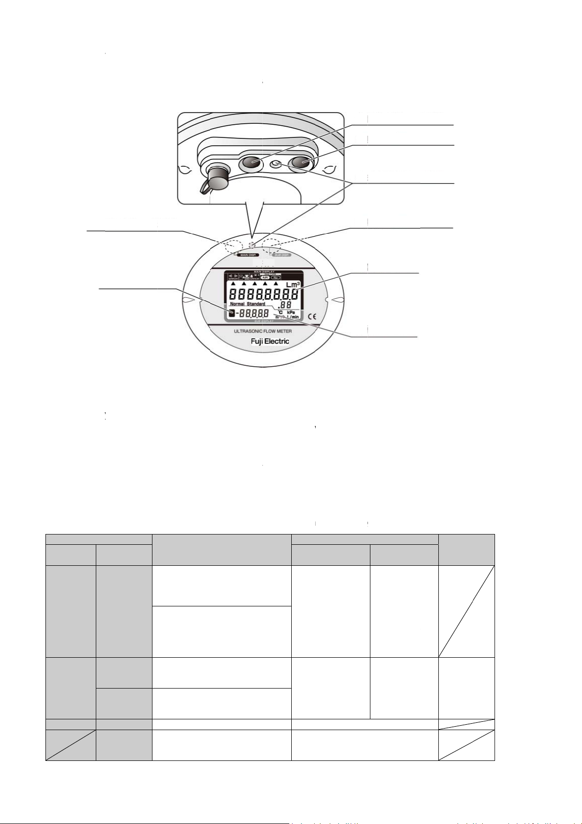
1-
. Name
Screw con
type
of each
nection
art
EXTERNA
S
ECIFICATION
AME PLATE
CONN
SE
BU
SET
OUTPUT
CTOR
TING
TON
CREW
DI
ULTR
PLAY SECTI
BODY
SONIC SENS
N
CASING
R
afer conn
ction type
6
Page 8

2. Installation
It is recommended that Setting Up (Page12 onward) and changing Panel angle
adjustment: (Page 11) are carried out before installation.
This flowmeter can be installed both indoors and outdoors and on a horizontal pipe and a
vertical pipe.
When a large amount of mist and/or dust exists inside pipe, the vertical piping is
recommended. When installing the flow meter horizontally, install it in such a way that the
display section faces upward.
This flow meter is not of a perfect waterproof structure (IP64). Do not install it at a place where
may be submerged in water.
The use of a sunshade is recommended if the flow meter is exposed to direct sunlight.
If you install the flowmeter in the place where it may get wet with rain, install the flowmeter so
that the display section does not face downward.
When you carry out the piping work, keep hands off inside the body and the ultrasonic
sensors (see Page 6) in particular.
Do not hold the display section of the flow meter.
Flow direction:
Mate the forward flow direction of a fluid to the arrow of the body.
7
Page 9
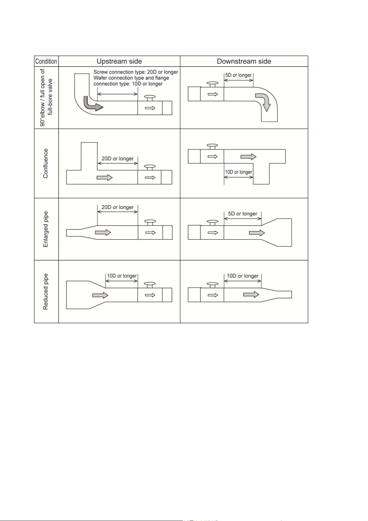
Straight run requirements:
Figure 2-1 Recommended straight pipe run
(D: nominal diameter)
8
Page 10
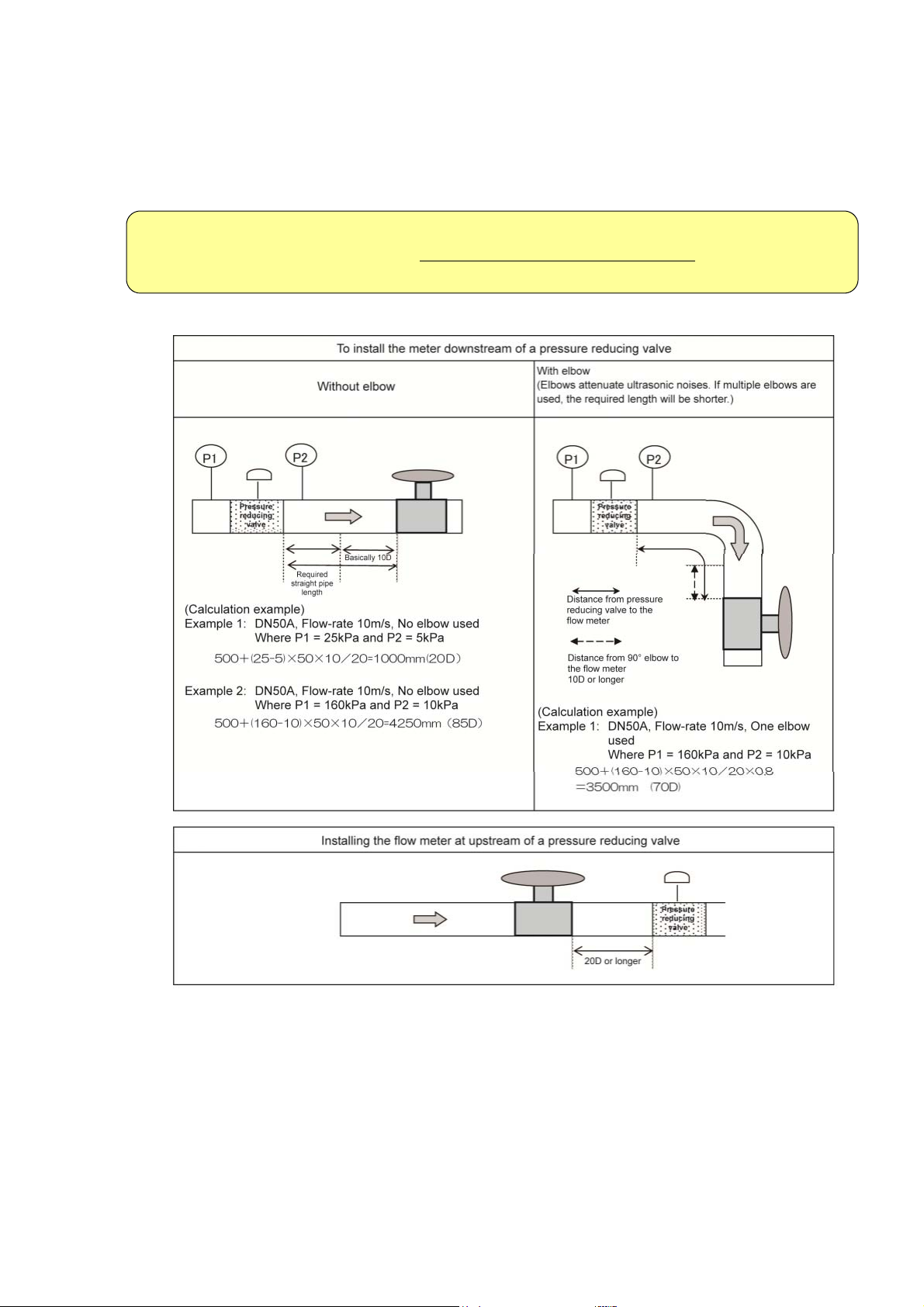
When the flow meter is installed near a pressure-reducing valve or a flow adjustment valve,
strictly observe the “required straight run L” as shown in Figure 2-2, because ultrasonic noise may
be generated inside the pipe.
Note that when the flow meter is installed at the downstream of the pressure-reducing
valve etc., there are many constraints. (If conditions are not satisfied, there is a possibility
that flow cannot be measured.)
Required straight run L (mm) =
10D differentialpressurekPa
⁄
20 ⁄
0.8
Figure 2-2 Required straight pipe run for installation near valve
9
Page 11
W
aFla
c
e
h
t
t
a
m
d
2
d
e
t
c
s
a
o
e
e
s
k
e
P
:
d
c
f
a
o
h
o
s
l
a
t
p
t
u
o
e
yFF
S
e
p
a
a
t
n
a
m
r
e
n
g
d
y
d
s
6
7
s
t
n
t
t
e
n
o
e
i
g
N
f
c
t
n
o
w
e
e
A
o
i
o
k
n
R
c
a
a
e
o
a
fer conn
nge type:
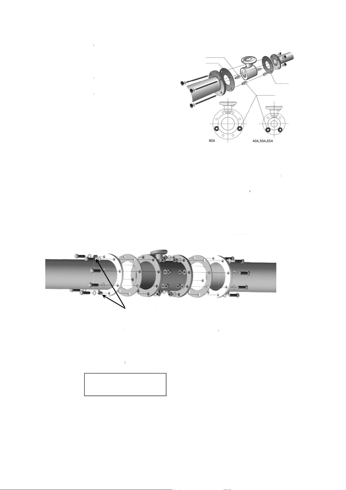
Install th
pipe. To
recomm
insert th
when in
Install t
flow me
connec
central
is reco
provide
Figure
provide
gaskets
to the c
flow me
it is diffi
both up
the mis
collars
ction type
e flowmete
er is aligne
ed. To redu
xes of the
mended th
as access
-3, insert t
as access
and flange
ntering col
er can be
ult to instal
tream and
lignment e
nly at the u
e flange ty
reduce the
nded that
centering
talling the
r so that th
to that of
e the displ
low meter
t the cente
ry be used
e centering
ry into the
. By fitting
ars, the ce
ligned to th
l the centeri
downstrea
c. of pipes,
pst
eam sid
e flow met
displaceme
he centerin
collars prov
pstream si
Figure
central axi
ipes to be
cement of
nd the pipe
ring collars
. As shown
collars
holes of fla
he flow me
tral axis of
t of the pip
ng collars a
sides due
install the
e.
r so that th
t of the ce
collars pr
ided as acc
e.
2-4 Attach
of the
he
s, it
in
ge
er
he
e. If
t
to
central axi
tral axes o
vided as a
ssory into
ng centeri
Figure 2-3
Centering c
Gasket
of the flo
the flow m
cessory be
he holes of
g collars
ttaching
llars
meter is al
ter and the
sed. As sh
flange pac
entering c
Centering co
igned to th
pipe, it is
own in Figu
ings and fl
llars
G
sket
llars
t of a
re 2-4,
nges
S
rew conn
Fix the fl
U
For
the wafer c
gas
owmeter b
STREAM
ets will not
ction typ
IDE
nnection t
extend insi
:
screwing it
WD025: 3
WD032: 4
CENTERI
pe and flan
e a pipe.
taper pipe
to 38 Nm
to 49 Nm
G COLLAR
e connecti
threads to
n type, tak
pipes within
DOWNST
care so th
the followi
EAM SIDE
at the flang
g torque ra
nge.
10
Page 12
Pan
e
d
y
e
y
c
t
o
l
e
p
f
h
t
p
c
c
o
e
y
h
n
e
k
1
d
m
e
e
l
o
e
s
s
s
e
o
o
U
N
l angle a
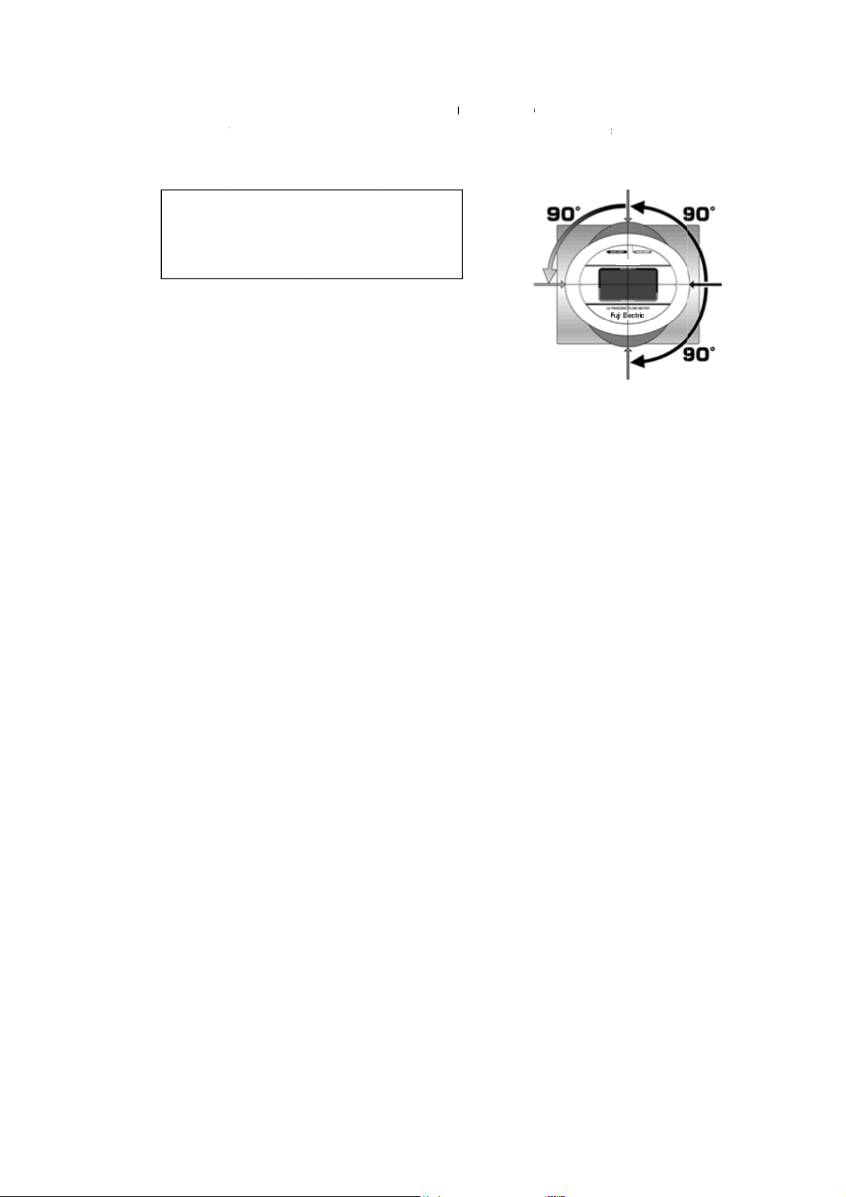
The displa
change th
the displa
display se
position.
The disp
clockwis
the setu
When rota
in a directi
justment:
can be rot
direction o
section wit
tion. Do no
ay section
and 180
at the fact
ing the dis
n other tha
ted. It is r
the displa
the M4 he
fail to fix t
an be rotat
ountercloc
ry.
lay section,
n the rotati
commende
section, te
xagonal wr
e display s
d by 90
wise from
do not app
g direction.
to change
porarily lo
nch provid
ction by tig
y force
the directio
sen a set
d as acces
tening the
n before in
crew on th
sory, and th
set screw a
tallation. T
neck part
en rotate th
t a desired
DEFA
SETTI
f
e
LT
G
1
Page 13

3. Setting Up
It is recommended that the setting of the flow meter be carried out before installation.
For this flow meter, 20 items shown in Table 3-1can be set. On delivery from factory, the “factory
default settings” in Table 3-1 are arranged, so that the flow meter can be used as it is. Change the
setting as necessary to make them suit to your working conditions.
See “4. Display” about button operations and setting methods.
Table 3-1 Setting items and standard factory settings
Setting item Setting options Factory settings
F1 Indication and output
Analog output
F2
full scale flow-rate
F3 State of contact output
F4 Contact output
F5 Lower limit alarm flow-rate -59999 to 59999 [m3/h] 0 [m3/h]
F6 Upper limit alarm flow-rate -59999 to 59999 [m3/h] 59999 [m3/h]
Alarm judgment value
F7
hysteresis width
Flow-rate moving average
F8
number of times
F9 Output pulse unit
F10 Pulse output method
Flow-value conversion
F11
selection
Standard conversion
F12
temperature
F13 Test mode time selection 3, 60, Unlimited [minutes] 3
F14 Fluid selection
Current output correlation
F15
value
F16 Low flow cutoff flow-rate 0 ≤ Set value ≤ Qmin*2 [m3/h]
Atmospheric pressure of
F17
the working environment
With or without pressure
F18
value averaging
Reset of all of
F00
accumulated values
Reset to standard factory
FFF
*1
delivery settings
Forward flow, forward and reverse
flow
0 to 99999 [m3/h]
Normal open,
Normal close
Reverse flow pulse, upper/lower
limit flow-rate alarm,
error alarm, electronic statement
output
3
0 to 9999 [m
01, 02, 04, 08, 16, 32, 64 [times] 04 [times]
Duty or one shot
50, 100, 125, 250, 500 [ms]
Yes (Normal),
Yes (Standard), No conversion
-10 to 60 [°C] 20 [°C]
Air (25A–200A)
Nitrogen (25A–80A)
Instantaneous flow-rate, pressure,
temperature
000.0 to 999.9 [kPa] 101.3
With (10 times), without (1 time) With (10 times)
To be cleared, not to be cleared Not to be cleared
To be reset, not to be reset Not to be reset
/h] 0 [m3/h]
Forward flow
25A:300
32A:600
40A:700
50A:1200
65A:2000
80A:2500
100A: 5000
150A: 10000
200A: 20000
Normal open
Upper/lower limit flow-rate alarm
100 [L]
1000 [L] for 100A and larger
Duty
Yes (Normal)
The kind of gas is set as the kind
specified at the time of order.
Instantaneous flow-rate
25A:0.1
32A:0.2
40A:0.2
50A:0.4
65A:0.6
80A:0.8
100A: 2.6
150A: 5.0
200A: 9.0
12
Page 14

Notes:
1. After resetting, "F9: Output pulse unit" will be set to 1000 [L], and “F14: Fluid selection” will be
set to Air.
2. Qmin is the following value depending on the nominal diameter.
25A 32A 40A 50A 65A 80A 100A 150A 200A
0.6 1.1 1.3 2.5 4.0 5.0 10.0 24.0 40.0
Setting items include the one related to fluid to be applied, the ones related to measurement and
indication, and the ones related to outputs.
[m3/h]
3-1. Measurement and indication setting
Settingrelatedtomeasurementandindication
Forwardflowor
Forward/reverseflow
Indicationandoutput
F1
Flowrateconversion
orActualflowrate
Flow‐rateconversion
F11
Indication of “Forward flow” or “Forward/reverse flow” [F1]
Indication of a main display is set.
When the “Forward flow” is selected, forward accumulated flow volume (total) or accumulated
flow volume (trip) can selectively be indicated on the main display by button operation.
When the “Forward/reverse flow” is selected, forward accumulated flow volume (total) or reverse
accumulated flow volume (total) can selectively be indicated on the main display by button
operation. When the analog output (4-20 mA) is selected for the flow-rate output, the electric
current value of the zero flow-rate output becomes 12 mA.
Flow-rate conversion
Select one among “actual flow-rate (OFF)”, "normal conversion flow-rate (Normal)", or "standard
conversion flow-rate (Standard)". If you select "normal conversion flow-rate (Normal)" or
"standard conversion flow-rate (Standard)", both indication and output of accumulated flow rate
and instantaneous flow rate are converted into the values under normal conditions or standard
conditions.
13
Page 15

3-2. Output setting (for external power supply type)
Pulseoutput
(reverseflow)
Alarmoutput
Instantaneous
flow‐rate
Pressure
Temperature
F3
Alarmoutput
F5
Lowerlimitalarm
F6
Upperlimitalarm
F7
Alarmjudgmentvalue
F2
AnalogoutputFSflow‐rate
Unitofoutputpulse
Opendrainoutput2
Currentoutput
Outputsettings
F9
Outputpulseunit
F4
Contactoutput
F15
Currentoutput
It is recommended that the setting of the flow meter be carried out before installation.
Current output [F15]
One of three output forms of instantaneous flow-rate, pressure and temperature can be
selected for the current output to suit your usage.
When the instantaneous flow-rate is selected, electric current corresponding to the setting of
the maximum flow-rate value of the analog output is outputted.
When the pressure is selected, 4 mA is outputted at the atmospheric pressure, and 20 mA is
outputted at 1 MPa.
When the temperature is selected, 4 mA is outputted at -10C, and 20 mA is outputted at
+60C.
Maximum flow-rate value of the analog current output (Analog output FS flow-rate) [F2]
When the analog output is used by setting to the instantaneous flow-rate, it is recommended
that full scale flow-rate (FS flow-rate) of the analog current output be set with a value
corresponding to maximum flow-rate used.
It is recommended that a numerical value having a margin be set as a set value of the FS
flow-rate.
(Setting example of the FS flow-rate: A set value at the time of nominal diameter 50mm,
flow-rate conversion “With(ON)”, room temperature (30°C), pressure 0.7 MPa, flow speed
10m/s: 600 m
3
/h)
14
Page 16

As a reference, Table 3-2 shows examples of conversion.
Table 3-2 Flow rate conversion examples
FWD025
FWD032
FWD040
FWD050
FWD065
FWD080
FWD100
FWD150
FWD200
Pressure
(MPa)
Temperature
(C)
0.6(m3/h) 0.6 0.5 3.6 3.2 4.7 4.3 6.4 5.8
35(m3/h) 35 32 210 190 280 250 370 330
1.1(m3/h) 1.1 1.0 6.5 5.9 8.7 7.8 12 11
65(m3/h) 65 59 390 350 510 460 690 630
1.3(m3/h) 1.3 1.2 7.7 7.0 10 9.3 14 13
80(m3/h) 80 72 470 430 630 570 850 770
2.5(m3/h) 2.5 2.3 15 13 20 18 27 24
150(m3/h) 150 135 890 800 1180 1070 1600 1440
4(m3/h) 4.0 3.6 24 21 32 29 43 39
240(m3/h) 240 220 1420 1280 1900 1710 2560 2310
5(m3/h) 5.0 4.5 30 27 40 36 53 48
300(m3/h) 300 270 1780 1600 2370 2140 3200 2880
10(m3/h) 10 9 59 53 79 71 110 96
500(m3/h) 500 450 2970 2670 3950 3560 5340 4810
24(m3/h) 24 22 140 130 190 170 260 230
1200(m3/h) 1200 1080 7120 6420 9490 8550 12810 11540
40(m3/h) 40 36 240 210 320 290 430 390
2000(m3/h) 2000 1800 11870 10700 15820 14250 21340 19230
0 (Atmospheric
pressure)
0 30 0 30 0 30 0 30
0.5 0.7 0.98
Output pulse unit [F9]
When a pulse output of the open drain output 1 (forward pulse output) is used, set the output
pulse unit in advance so as to suit your working conditions. The output pulse unit set here is
reflected in the open drain output 2 (reverse flow pulse output), too.
Contact output [F4]
You can select from the pulse output (reverse flow), the flow-rate upper/lower limit alarm output,
and the main unit aberration output. When the pulse output (reverse flow) is selected, set the
output pulse unit. However, when the output pulse unit is set in advance for the use of the open
drain output 1 (forward flow pulse output), it is not necessary to set it here.
For the upper/lower limit alarm output, an alarm can be outputted or stopped with a desired
flow-rate value.
When this function is selected, set the alarm output contact state (F3), the lower limit alarm
flow-rate (F5) and the upper limit alarm flow-rate (F6), and the alarm judgment value hysteresis
width (F7).
15
Page 17
4.
B
B
B
y
n
y
o
i
r
o
n
SBAC
P
o
y
a
t
b
t
e
CaainCare(t(L
P
C
C
R
z
T
m
p
c
a
o
r
f
f
m
a
f
m
o
o
t
h
c
t
s
o
r
m
o
o
l
u
e
o
u
p
w
s
W
w
m
oin
g
s
g
o
g
g
a
e
c
n
h
W
g
a
a
l
CBABABACMAI(UPSUB
W
o
r
s
n
f
f
a
o
U
T
U
M
u
o
m
d
o
v
e
]
W
]
Displa
Fig
Back side of
ure 4-1 Dis
he panel
play and b
ttons
BA
K RIGHT B
TTON [SW2
4-
1. Butto
Usuall
Variou
See F
By pe
Table 4-1
flow v
on the
as sh
K LEFT BUT
ILOT LAMP
operati
is the me
lume, and
s individual
back of the
gure 4-1 a
forming but
wn in Figur
How to op
ON [SW1]
ns
surement
he sub-dis
setting item
display se
out the arr
on operati
4-2.
erate butto
ode, and t
lay (lower
s can be se
tion.
ngement of
ns in Table
ns in mea
e main dis
olumn) sho
t at a local
“SW1”, “S
4-1, the flo
urement
(LO
lay (upper
s instanta
ite by the t
2” and “S
meter can
ode, settin
CK LEFT BU
CK CENTER
K RIGHT B
N DISPLAY
PER COLUM
-DISPLAY
ER COLU
olumn) sh
eous flow-
ree button
3.”
be shifted t
mode, a
TON [SW1]
BUTTON [S
TTON [SW2
N)
N)
ws accum
ate.
witches pr
o various
d test mo
3]
lated
vided
odes
e
utton positio
Button
position
Back left
ack right
ack center
and name
Name
SW1
SW2 Cfl
SW2 for
three
seconds
SW3
W1+SW2
hangeover o
ccumulated fl
ccumulated fl
stantaneous
hangeover o
ccumulated fl
verse accu
otal) / instant
/min)
hangeover o
ow-late (m3/h
ressure / te
hangeover t
hangeover t
esetting of tri
1)
ero3)
Measu
ement mode
Forward
ow volume (t
ow volume (t
flow-late (L/
Forward
ow volume (t
ulated flow v
neous flow-
Instantaneo
/
perature
test mode
setting mod
p accumulati
2)
tal) /
ip) /
in)
ate
Chan
next
tal) /
lume
s
Chan
previ
item
Chan
Chan
n to
indic
and s
L
cal setting
dication
eover to the
etting item
eover to the
us setting
eover to me
eover of loc
tion
tting of detai
Setting
mode
Setting o
details
Changeover
setting detail
Movement o
blinking digit
Change of a
numerical v
at a blinking
portion
surement m
l setting
s
f
of
s,
f
lue
de
Test m
Switcho
measur
mode
de
er to
ment
16
Page 18

Notes:
(
[
]
1. “SW1+SW2” indicates that two switches are pressed simultaneously.
2. Indication cannot be changeover when the main display shows the instantaneous flow-rate
[L/min].
3. Accumulated flow volume (trip) is reset to zero in the following cases:
When SW1+SW2 are pressed during the indication of accumulated flow volume (trip)
If power supply is interrupted by a power failure [External power supply type]
Figure 4-2 Transitions between each operation mode
Main display (Forward flow
メイン表示(正流表示モード)
display mode)
Accumulated flow
正積算流量
volume
計
測
Sub-display (When main display displays Accumulated flow volume (Forward flow), Trip accumulated flow
モ
サ ブ 表示( メイン 表示が正 積算流量、 トリッ プ積 算流量、 逆積算流 量のい ずれかの 場合)
volume, or Accumulated flow volume (Reverse flow))
|
Instantaneous flow
瞬時流量 圧力 温度
ド
Forward flow)
SW1
SW2
Measuring modes
SW3
Transition to settings mode
設定モードへ遷移
Clear trip accumulated flow volum e
SW1+SW2/ トリップ積算クリア
Trip accumulated flow
トリ ップ積 算流量
volume
SW1
Pressure
SW3 or three minutes of
SW3 or3min
inaction.
SW1
SW2
1min
One minute
elapses.
経過
SW2 or one minute elapses.
SW2
無操作
Instantaneous flow-rate
瞬時流量
Temperature
or1min経過
Switchover using
settings mode [F1]
[L/min]
SW2 (3s)
設定モード[F1]で切換
Transition to test mode
テストモードへ遷移
メイ ン表示(正逆流表示モード)
Main display (Forward flow display m ode)
ブランク
Blank
SW1
Accumulated flow rate
逆積算流量
(Reverse flow)
SW1
[L/min]
)
Accumulated flow
正積算流量
volume (Forward flow)
Sub-display (main display) under insta ntaneous flow-rate [L/min]
サブ 表示(メイン表示:瞬時流量の場合
SW2 (3 sec.) or test mode
SW 2 (3s ) or テス トモ ード
time ended.
時間終了
SW1
Instantaneous flow-rate
瞬時流量 [L/min]
L/min
17
Page 19

4-
2
e
a
n
m
m
e
c
W
•
e
r
s
y
h
o
m
s
e
r
0
o
a
t
u
3
s
p
o
4
a
u
a
4
m
p
y
s
e
n
m
d
m
w
o
e
u
w
a
n
m
r
a
e
r
a
s
l
o
u
w
d
]
t
m
e
d
e
e
n
l
e
9
i
f
m
o
o
u
a
u
i
. Oper
M
asureme
tion mod
This
mode is fo
this
The
(low
r column) s
Swit
• Each ti
t mode
ode unles
ain displa
hover of t
hen the f
to insta
flow).
s
measuring
you opera
(upper col
hows the in
Figure 4-
e main di
rward flow i
e SW1 is
ntaneous fl
Figure
flow-rate,
e any of its
mn) displa
tantaneou
Exampl
play
s selected i
ressed, the
w-rate [L/
-4 Main
ressure, a
buttons.
s the accu
flow-rate.
of measu
[F1: Indic
display will
in] and th
isplay (fo
d temperat
ulated flo
ement mo
tion/output
cycle from
n to accu
ard flow)
re. The m
volume, a
e
rip accumu
ulated flow
ter will re
d the sub-d
lated flow v
volume (f
ain in
isplay
lume
rward
Accumul
tedflowvolu
e
Tri p
ccumulatedfl
wvolume
Instantaneous
flow‐rate[L/m
n]
By pre
display
If the t
show
operati
sing SW1
d, trip acc
ip accumul
000000.0
ns.
nd SW2 si
mulated flo
ted flow v
without z
ultaneous
volume c
lume overfl
ro suppre
ly while trip
n be canc
ows beyon
sion and
accumulat
led.
9999999.
continue
d flow vol
, the displ
its accum
me is
y will
lation
Figure
-5 Trip acc
mulated f
ow volum
No overflo
Overflow
18
Page 20

h
s
h
h
nWhe
o
m
t
t
o
r
t
a
s
a
s
b
t
a
l
c
en forward
/
e
o
g
e
M
n
2
a
c
o
e
e
d
c
f
d
y
y
a
n
a
w
w
r
s
)
a
a
d
a
d
h
t
e
s
m
e
e
e
e
e
n
n
r
4
4
9
d
d
a
-
n
f
t
w
e
2
e
w
e
s
l
/
t
v
i
L
e
e
p
a
e
W
/
d
t
d
t
d
m
u
)
e
o
m
i
e
o
”
a
o
a
r
o
a
e
c
c
o
c
a
t
e
f
3
t
e
n
r
n
s
W
•
Each tim
(Reverse
volume (f
reverse flo
SW1 is p
flow) to in
rward flow
Fi
ure 4-6 M
is selecte
essed, the
tantaneous
.
in display
in [F1: Ind
display will
flow-rate [
(forward/r
cation/outp
cycle from
/min] and
verse flow
t]:
accumulat
then to ac
)
d flow volu
umulated f
me
low
Test
mode
The test m
‒ Perfor
‒ During
‒ Test m
‒ When
‒ When
‒ An inst
Sub-di
In t
volu
Eac
mai
the i
during
flow-ra
interval
setting
measu
during
there i
there i
*Possi
convec
place.
Examp
A
cumulatedflo
(Forwardfl
play (low
e case of [
me (trip), a
time “SW
tenance
n one minu
ndication is
de is a fun
the test m
he measur
e can be m
the test mo
s of 0.5 se
de times o
mode. Whe
ement mod
he test mo
n indicated
a possibilit
n indicated
a possibilit
ility of leak
ion, etc., it
ntaneous f
e) Indicatio
Indic
volume
ow)
r column)
ain display
d reverse
” is presse
*1)
nd instant
te elapses
shifted to t
tion that re
de in a sta
ment mod
asured.
e, a unit of
onds.
three kind
n the set ti
e [F13]. Wh
e, it is shift
value of th
of leakag
value of th
of leakag
ge: As an i
indicates o
low-rate du
: 0 to 0.00
tion: -0.00
Accumula
(Re
: Forward a
ccumulate
,” the indic
neous flow
uring the i
e instantan
leases low
e of no flo
, the mode
the sub-dis
of 3 minut
e elapses,
en the “SW
d to the m
instantane
* at the do
instantan
* at the up
dicated va
ly a possibi
ing the test
[m3/h] →
to 0 [m
3
h]
edflowvolum
erseflow)
ccumulated
flow volum
tion chang
rate.
dication of
eous flow-r
low cutoff t
. When “S
is shifted to
3
play (“m
h”
s, 60 minut
the test mo
” is presse
asurement
ous flow-ra
nstream si
ous flow-ra
tream side.
ue includes
lity.
mode is in
0.00 [m3/h]
→ -0.00 [
e
Instant
flow volum
e (total)]
s in order
ressure, te
te automat
mporarily.
2” is press
the test m
, “kPa”, “C
s, and no l
e is autom
for 3 sec
mode.
e is a flow-r
e.
e is a flow-
offset of ze
icated by r
3
/h]
neousflow‐ra
(total), ac
f pressure,
mperature
ically.
ed for 3 se
de so that
, “L/min”) b
imit can be
atically shif
nds or mor
ate value of
ate value o
ro flow-rate
unding at
e[L/min]
umulated fl
temperatur
r maintena
onds or mo
very small
inks at the
selected in
ed to the
once agai
(+)0.1 or m
-0.1 or les
inside
rd
decimal
ow
,
ce,
e
the
ore,
,
1
Page 21

Setting mode
‒ Press “SW3” to shift the flow meter to the setting mode. To shift from the setting mode to the
measurement mode, press the “SW3” again. When no operation is made for 3 minutes in
the setting mode, it is shifted to the measurement mode automatically. Press the“SW3” with
the M4 hexagonal wrench provided as accessory, etc. Note: “SW3” may be broken if
pressed by a sharp pointed tool.
‒ In the setting mode, setting details shown in the “Table 3-1 Setting items and standard factory
settings” (Page 12) can be changed.
‒ See figures of changeover of indication of various setting modes in Figure 4-2 for button
operation methods in the setting mode.
20
Page 22

4-3. Setting items
[F1] Indication/output
In the indication/output, “forward flow (d.F.)” measurement or “forward/reverse flow (d.r.F)”
measurement is selected.
When the “forward flow” measurement is selected, the “forward accumulated flow volume (Total)”
or the “accumulated flow volume (Trip)” can be indicated on the main display by button operation.
When the instantaneous flow-rate is set with the analog output (4-20 mA), 4 mA becomes zero
flow-rate.
When the “forward/reverse flow” is selected, the “forward accumulated flow volume (Total)” or
“reverse accumulated flow volume (Total)” can be indicated on the main display by button
operation. The trip function cannot be used. When the instantaneous flow-rate is set with the
analog output (4-20 mA), 12 mA becomes the zero flow-rate.
See “4. Description of operation of display section” about the button operation.
[F2] Analog output FS (Full Scale) flow-rate
This function sets a full scale flow-rate value when the instantaneous flow-rate is set with the
analog output. On delivery from factory, the flow-rate value shown in the Table 3-1 or Table 3-2 is
set. When in use with the NORMAL conversion set to “With (ON)” set a NORMAL conversion
value.
[F3] State of contact output
Select "Normal open (n. OP)" or "Normal close (n. CL)."
Set this to "Normal open" in case of using a battery-powered signal receiving device.
[F4] Contact output
Select the output signal of open drain output 2 from “pulse output (reverse flow) (PULS),”
“main unit aberration output (Err),” “upper/lower limit flow-rate alarm output (AL),” and
“electronic statement output (COdE).”
“Main unit aberration output (Err)” outputs signals when one of the following occurs: ultrasonic
measurement aberration, pressure measurement aberration, temperature measurement
aberration, battery voltage reduction (for the built-in battery version only), and elapse of 11
years.
[F5] Lower limit alarm flow-rate
Use this to set the lower limit alarm flow-rate (5 digits) as the lower limit flow-rate value for the
upper/lower limit flow-rate alarm.
* This is the judgment value for flow-rate lower limit alarm output of open drain output 2.
[F6] Upper limit alarm flow-rate
Use this to set the upper limit alarm flow-rate (5 digits) as the upper limit flow-rate value for the
upper/lower limit flow-rate alarm.
* This is the judgment value for flow-rate upper limit alarm output of open drain output 2.
[F7] Alarm judgment value hysteresis width
With regard to the flow-rate value defined for the upper/lower limits of the upper/lower limit
flow-rate alarms, a hysteresis width range (4 digits) is defined for the alarm judgment value as
the range of flow-rates for terminating the alarm.
*This is the judgment value for flow-rate upper/lower limit alarm output of open drain output 2.
21
Page 23

[F8] Flow-rate moving average number of times
This denotes the moving average number of times for the instantaneous flow-rate
measurement results.
Instantaneous flow-rate for display and output is the value that the moving average is applied
for the defined number of times of the most recently measured instantaneous flow-rate.
While this is usually set to “4 times (04)” and does not need to be changed,
you can choose from “No moving average (01),” “2 times (02),” “4 times (04),” “8 times (08),”
“16 times (16),”
“32 times (32),” and “64 times (64).”
[F9] Output pulse unit
Select the weight (unit: L/P) of the output pulse from 10 L/P, 100 L/P, and 1000 L/P.
The range of the setting is limited depending on the nominal diameter and settings you have
made in [F10] Pulse output mode or [F11] Flow-value conversion selection. Please see the
following table for details.
Figure 4-7 Output pulse unit selections
22
Page 24

[F10] Pulse output method
Select from one of the five one-shot modes (ON time “50ms,” “100ms,” “125ms,” “250ms,” or
“500ms”) or Duty mode. Selecting one of the one-shot modes is recommended in case the
signal receiving instrument you are using is battery-powered. Make sure to check the
specifications of the signal receiving instrument and set the appropriate ON time from Figure
4-7.
[F11] Flow-rate conversion selection
Select "actual flow-rate (OFF)", "normal conversion flow-rate (Normal)", or "standard
conversion flow-rate (Standard)" for flow value conversion. If you select “normal conversion
flow-rate (Normal),” the “Normal” lamp above the partition line will flash. If you select “standard
conversion flow-rate (Standard),” the “Standard” lamp will flash. If you select “No conversion,”
both lamps will turn off. The accumulated flow volume display, instantaneous flow-rate display,
and output signal will all correspond to the selection of whether to convert the flow-rate or not.
See below for the definition of flow-rate conversion and the conversion equation.
/h
273.15
273.15
Q
: Normal conversion flow-rate [m3/h]
2
t: Measured temperature [°C]
P
: Measured pressure [kPa]
1
q
: Actual flow-rate [m3/h]
1
/h
273.15
273.15
Q
: Standard conversion flow-rate [m3/h]
2
T: Standard conversion temperature [°C] [F12]
t: Measured temperature [°C]
P
: Measured pressure [kPa]
1
q
: Actual flow-rate [m3/h]
1
[F12] Standard conversion temperature
This is used to set the temperature [ºC] to use as the basis for standard conversion. The
temperature can be set within a range between -10ºC and +60ºC in 1ºC increments. This
setting is not available if an option other than standard conversion is selected in [F11].
[F13] Test mode time selection
Test mode times available for selection are "3 min. (3)," "60 min. (60)," and "Unlimited (--)."
During test mode, the unit on sub display blinks.
[F14] Fluid selection
Select either "Air (Air)" or "Nitrogen (N2)." Even if you specified a flow meter for air in your
initial order, you can change this setting so that it can be used for nitrogen.
[F15] Current output correlation value
Select "Instantaneous flow-rate (FLo)", "Pressure (PrS)", or "Temperature (tEP)" for the
functional assignment of the current output. When instantaneous flow-rate is selected, the
instantaneous flow-rate correlation value that you have selected in [F11] Flow-value
conversion selection will be used.
17
101.33
17
101.33
23
Page 25

[F16] Low flow cutoff flow-rate
This is for setting the low flow cutoff flow-rate (Qcut) where the instantaneous flow-rate is
0m3/h.
The settable range is defined as 0 ≤ Qcut ≤ Qmin.
The set flow-rate will be the flow-rate you selected in [F11] Flow-value conversion selection.
[F17] Atmospheric pressure of the working environment
This is used to set the atmospheric pressure value (4 digits) [kPa] of the working environment
in absolute pressure. The standard factory setting has been set to 101.3 [kPa]. Leave this
setting unchanged unless you are operating the meter at higher elevations, etc.
[F18] With or without pressure value averaging
Set with or without pressure value averaging to either "With averaging (10)" or "No averaging
(1)." If "With averaging" is selected, the moving average value of the 10 most recently
measured pressures is used for display and output.
[F00] Reset of all of accumulated values
By selecting "Clear (cLr)", the values for Accumulated flow volume (Forward flow),
Accumulated flow volume (Reverse flow), and Trip accumulated flow volume are reset to zero.
[FFF] Reset to standard factory delivery settings
By selecting "Reset (SEt)", settings are reset to standard factory settings shown in Tab le 3-1.
However, "F9 Output pulse unit" alone will be set to 1000L/P for all nominal diameters, and
“F14 Fluid selection” will be set to Air.
24
Page 26

Fi
g
m
n
n
g
A
v
s
5
v
g
u
A
s
e
put
e
c
S
m
o
m
e
W
n
n
SW3
Setting
ure of cha
or no operation for
3 minutes
ode
geover of i
Fi
Measurement
mode
Display · output
nalog output
dication of
ure 4-8 Di
Forward flow outpu
Flickering
arious sett
play chan
Forward/reverse flow outp
t
Flickering
ing modes i
eover in s
t
Flickering
shown bel
tting mod
Flickering Fl
ow.
e
ickering
* Use SW2
portion.
* Displays t
as select
conversio
to increment flickering
he converted informatio
d in F11 “Flow rate
selection."
State of contact
output
Contact output
Alarm output lower
limit flow-rate
Alarm output upper
limit flow-rate
Alarm judgment
value hysteresis
width
Flow-rate moving
average number of
times
Normal open
Pulse
Normal close
larm
Main unit
aberration out
lectronic
* Use S
2 to increment
flickeri
g portion.
Flickering
Flickering
Flickering
Flickering
4 times
Flickering
Flickering
Flickering
8 times
Flickering
Flickering
Flickering
16 times
Flickering
Flickering Fli
Flickering
* Use
incre
porti
32 times 64 ti
Flickering Fli
kering
W2 to
ent flickering
n.
mes 1 time
Flickeri
ckering
* Use SW2 to
increment
flickering
portion.
2 times
Output pulse
unit
2
Page 27

)
At
t
)
出力パルス
Output pulse unit
F9
単位
SW1
(Other than standard
(スタンダード換算以外)
conversion)
SW2
(Other than standard
(スタンダード換算以外)
conversion)
SW2 SW1
出力パルス
F10
SW2
F11
SW2
F12
SW2
SW2
(Standard
(スタンダード換算)
conversion
Test mode time
テストモード
F13
SW2 SW1
F14
SW2 SW1
Current output
F15
correlating value
SW2
Low flow cutoff
F16
カットオフ値
SW2
使用環境の
pressure in the
F17
SW2
With or without
pressure value
F18
平均化有無
SW2
Clear accumulated
積算値クリア
F00
SW2
Reset parameters
FFF
Output pulse
selection
選択
Flow-rate
流量換算
conversion
有無選択
selection
Standard
スタンダード
conversion
換算温度
temperature
selection
時間選択
Kind of gas
ガス種
電流出力
相関値
ローフロー
mospheric
operating
大気圧
environmen
圧力値
averaging
values
パラメータ
リセット
SW1+SW2
SW1+SW2
SW1
SW1+SW2
SW1+SW2
SW1
SW1
(Standard
(スタンダード換算)
conversion
SW1+SW2
SW1+SW2
SW1
SW1+SW2
SW1+SW2
SW1+SW2
SW1+SW2
SW1+SW2
SW1+SW2
SW1
SW1+SW2
SW1+SW2
SW1
SW1+SW2
SW1+SW2
SW1
SW1+SW2
SW1+SW2
SW1
SW1+SW2
SW1+SW2
SW1
SW1+SW2
SW1+SW2
One-shot pulse:
ワンショットパルス:50ms
50 ms
No conversion
換算なし
SW2 SW2
3 min
3分
Air
Flow-rate
流量
Flickering Flickering Flickering
Flickering Flickering Flickering Flickering
With averaging No averaging
有り(10回)
Not to be
クリアしない
Not to be reset
One-shot pulse:
ワンショットパルス:100m s
100 ms
SW1
Normal conversion Standard conversion
ノルマル換算
SW1
Flickering
点滅
SW1
Flickering
点滅
SW1
空気
SW1
SW2
Pressure
SW1
点滅
SW1
SW1
無し(1回)
SW1
SW2
To be cleared
クリアする
SW1
SW2
To be reset
リセットするリセットしない
SW1
SW2
One-shot pulse:
ワンショットパルス:125ms
125 ms
SW1 SW1 SW1
SW1
スタンダード換算
SW1
SW1
Flickering
点滅
SW1
SW1
60 min
60分
SW1
Nitrogen
窒素
圧力 温度
SW1
点滅点滅 点滅
SW1
点滅
Unlimited
無制限
SW1
Temperature
SW1SW1
SW1
SW1 SW1
点滅
One-shot pulse:
ワンショットパルス:250ms
点滅
Flickering
* Use SW2 to increment f lickering
※SW2で点滅部
インクリメント
* Displays the converted inf ormation as
※F11「流量換算選択有無」にて
One-shot pulse:
ワンショットパルス:500ms
※SW2で点滅部
flickering portion.
インクリメント
500 ms
SW1
250 ms
* Use SW2 to increment
portion.
selected in F11 “Flow rate conversion
選択した換算情報が表示される
selection.”
点滅
* Use SW2 to increment
※SW2で点滅部
flickering portion.
インクリメント
duty
26
Page 28

5. Wiring (External Power Supply Type)
Please be sure to conduct the wire connection using the optional cable for external connection
as follows.
Figure 5-1 Wiring diagram
The main body and GND are electrically common.
Use an isolated power supply and a remote display as necessary.
Notes:
1. When installing the flow meter around an electric noise source, ground the braided
shield of the external connection cable.
2. Cut off the brown lead wire at its root to prevent it from contacting others.
3. Do not perform the insulation resistance and withstand voltage test.
27
Page 29

Note on open drain output setting
This meter gives you a choice of two types of outputs: duty output and one-shot output. The
meter is set to duty output when it leaves the factory.
Under duty output, the ON:OFF times are 1:1. Under one-shot output you can set the ON
times shorter between 50 to 500ms (Figure 5-2). Therefore, if you are using a battery-powered
pulse receiving signal receiver, using a one-shot pulse output is recommended to improve
battery life.
Please keep the following points in mind with regard to selecting one-shot.
Check the waveform corruption caused by the cable (line capacity, line resistance) and
the minimum input signal width of the signal receiver to choose the appropriate ON
time.
ON/OFF will reverse if you choose "Normal close."
Figure 5-2 One-shot output and duty output
(Example with pulse constant at 1000L/P, and Normal open)
Example of pull-up resistance calculation
Check the pulse receiving signal receiver's specifications (power supply voltage Vdd [V] and
ON current Ion [mA]) and select the pull-up resistance constant using equation (1).
R[Ω]=[(Vdd-0.2)/(Ion×10-3)]-24.7・・・(Equation 1)
*Do not allow the current Ion to exceed the maximum load of 24 VDC and 50 mA.
Example where Vdd=24V and Ion=10mA
R[Ω]=[(24-0.2)/(10×10-3)]-24.7=2355[Ω]≒2.2[kΩ]
28
Page 30

6.
O
n
r
n
c
n
p
u
t
a
e
m
a
u
t
e
9
s
a
w
a
n
r
a
t
m
f
a
r
g
Ope
diffe
Whe
(A fli
peratio
Do not o
ing or closi
ence is occ
you are r
kering pilo
en or close
ng of the v
urring betw
nning the
lamp indic
valves abr
lve all at on
en the ups
eter for the
tes that th
Figure
ptly. Make
ce may cau
ream side
first time, c
fluid is flo
6-1 Indic
ure to ope
se a failure
nd downst
heck that th
ing.)
tion at st
and close
of the flow
eam side o
e pilot lamp
rt-up
hem gradu
eter if a p
the valve.
is flickerin
lly.
essure
.
2
Page 31

7.7- Alarm
a
e
p
TAa
p
eOnmeatm
o
o
a
a
c
p
d
s
s
l
p
t
u
u
-
A
n
t
i
F
t
h
w
g
f
e
g
e
r
u
p
o
i
i
s
t
t
b
e
s
u
b
c
s
m
s
a
o
r
h
g
l
m
e
o
g
a
m
1. Aberr
[Stat
[Dis
[Out
[Cau
tion in fl
] Unable
lay] The tri
he instant
s for the a
nd the dis
ut] Analog
Open
se] There i
to or is
of ultra
If the a
branch
Fi
w meas
to receive
ngle in the
neous flow
cumulated
lay shows t
output: 4m
rain output:
a possibili
being retai
onic.
arm persis
or sales off
gure 7-1
rement
ltrasonic si
upper left o
rate value i
flow volum
he value im
Stopped
y that forei
ed in the m
s even afte
ce.
low meas
nals.
the LCD fl
n the sub-d
value disp
mediately p
n material
easuremen
removing
rement a
ckers.
splay show
ay, the acc
rior to the a
(liquids su
pipe, and i
he foreign
erration di
"0.00."
mulation p
erration.
h as oils)
obstructin
aterials, p
play
ocess is st
as become
the propa
lease conta
pped
stuck
ation
ct our
(Not
ce the flow
asurement
w
rking condi
) Actions w
ospheric
hen the me
meter is in
aberration
ressure. T
ions. (This
er is first ru
stalled and
display" d
is will sto
ill return t
n
measurem
ue to the
once the
normal.)
nts begin,
sudden ch
pressure
the meter
nge in pr
f the fluid
ay show
essure fro
stabilizes
"flow
the
under
30
Page 32

7-2.
n
y
n
m
o
s
t
]
a
a
n
y
a
s
t
]
e
e
s
u
a
m
u
i
]
s
e
o
m
a
a
e
e
u
u
m
s
u
i
]
r
m
n
F
f
h
v
)
A
t
e
o
m
e
h
p
s
A
t
a
e
T
r
1
s
d
l
m
c
o
p
u
e
u
m
m
a
e
a
d
h
w
m
p
s
n
v
u
y
a
g
s
n
m
e
a
0
b
n
s
b
0
h
a
i
u
t
s
n
r
u
t
f
m
e
e
k
a
r
m
p
e
n
l
t
r
s
F
e
Aberra
t pressur
value
[State]
[Displa
The i
of te
As f
stop
[Outpu
[Cause
Accumul
This stat
] The pres
stantaneo
perature v
r the accu
and the dis
] Analog o
Open dra
The pres
Other pot
or sales
ted flow volu
nd accumul
indicates t
ure display
s flow-rate
lue flashes
ulated flow
play shows
tput: 4m
n output: S
ure used m
ntial caus
ffice.
Figure 7-2
e (forward fl
ted flow volu
at the pres
in the sub-
alue in the
volume va
the value i
opped
ay have ex
s include p
Pressure
ow), trip accu
e (reverse fl
ure value
isplay sho
sub-display
ue in the
mediately
eeded the
ressure se
aberration
mulated flow
w) displays
as exceed
s the aberr
shows "0.0
ain display,
rior to the a
pecified ra
sor failure,
displays
olume, In
d the mea
ant value a
" and flicke
the accum
erration.
ge.
please con
tantaneous
(L/
urement li
d flickers.
s. (The dis
lation proc
act our bra
low- rate disp
in)
its.
lay
ss
ch
ay
7-3.
Aberra
[State]
[Displa
The i
displ
As fo
stop
[Outpu
[Cause
t temper
This stat
limits.
] The temp
nstantaneo
y of press
r the accu
and the di
] Analog o
Open dra
The aber
does not
getting a
ture valu
indicates t
rature dis
s flow-rate
re value fla
ulated flow
play shows
tput: 4m
n output: S
ant temper
atch the fl
aberrant t
igure 7-3
at the tem
lay in the s
value in th
hes)
volume val
the value i
opped
ture alarm
uid being
mperature
emperatur
erature val
b-display s
sub-displa
e in the m
mediately
may be trig
easured. If
larm, plea
aberratio
e has exce
hows the a
shows "0.
in display, t
prior to the
ered if sett
the setting
e contact o
displays
eded the m
errant valu
0" and flic
he accumul
berration.
ing of Fluid
is correct a
ur branch o
asuremen
and flicke
ers. (The
tion proce
selection [
nd you are
sales offic
s.
s
14]
still
.
Accumulated
flow volume (
and
accumulated
forward flow),
low volume (
trip accumul
everse flow)
ted flow volu
isplays
e, Instan
aneous flow-
(L/min)
rate display
3
Page 33

7-
4
o
e
p
p
s
t
a
a
e
s
y
s
y
h
h(Re
aRe
aRe
h
u
s
e
rMem(S
a
a
u
w
o
d
o
h
eFig
r
r
t
a
s
t
e
s
e
i
g
g
b
n
n
e
e
b
s
r
t
An
t
o
-
h
o
e
h
o
m
w
s
t
n
o
2
r
m
s
e
h
e
t
p
r
e
u
e
r
a
a
tStSt
o
t
s
a
e
c
e
"
"
. Mem
[Stat
[Dis
[Out
[Cau
ry aberra
] There is
[1]
User's are
[2]
System ar
lay] [1] U
ut] [1] U
e] [1] In t
: An
a: An
er's area:
[2] S
stem area:
er's area:
[2] S
stem area:
e case of a
C
If
eck to see
ny aberrati
set to stan
If
set of all of
*Pl
ease note t
[2] In t
Please
e case of a
contact our
ion
n aberratio
ch
dat
by
fer to Table
ny aberrati
Figure
in the dat
berration i
nged by bu
upon pow
berration i
sers is not
The tr
nitrog
The d
Analo
Open
Analo
Open
memory a
hether the
3-1.)
ns are fou
ard factory
ns are fou
accumulat
at this res
memory a
branch or
7-4 Memo
in the non
found in t
ton operati
ring the m
found in t
available).
iangle that i
n) flickers.
isplay show
output: N
drain outpu
output: 4
drain outpu
erration in t
set data is
d with the
delivery set
nd with the
d values" a
ts your sett
erration in t
ales office.
y aberrati
volatile me
e data for
ns, or in th
ter on.
e data for t
ndicates th
s "E-2."
rmal opera
t: Normal o
t: Stopped
he user’s a
ithin the s
et data, yo
ings." (*)
accumulat
d power th
ings data o
he system
n display
ory.
ettings that
accumulat
e system (
Kind of G
ions
erations
ea
ttable rang
can reset t
d value dat
meter ba
accumulat
rea
were
ed value
etting
s (air or
e.
hem using
a, perform
k on. (*)
d value.
[FFF]
[F00]
[1] Us
r’s area
[
] System a
rea
Meas
Pre
Te mp
Memo
rement abe
sure aberra
rature aber
y aberration
area)
ory aberra
ystem area
ure 7-5 Ou
ration
ion
ation
(User
ion
)
put at abe
alog output
4mA
4mA
4mA
Normal
perations
4mA
rations
Open dr
Normal
in output
S
op
op
op
perations
S
op
32
Page 34

8. Power Interruption (External Power Supply Type)
Detection of power failure
The drop of a power source voltage to 18±1.1V or lower is judged to be a power failure. As a
result, the measurement is stopped, and the last accumulated value is stored, and the LED
display is turned off.
Reset from power failure
When a power source voltage rises to 18.8±1.1V or higher, the measurement is resumed with
the total value recorded right before the power interruption, and the LED is turned on.
33
Page 35

9. Battery Life (Built-In Battery Type)
The life of the built-in battery is 10 years. (This is the life at the environment temperature of 20C.
The battery life fluctuates depending on conditions such as the ambient temperature and output
settings.)
* In the case the battery run out earlier due to reasons of high environment temperature, etc., the
battery is possible to be replaced at our plant as a fare-paying service. Contact our branch or
sales office nearby.
34
Page 36

10.
ycon
n
e
b
t
a
e
v
a
o
u
c
a
e
a
t
t
l
e
v
t
t
e
m
a
o
i
m
o
a
h
s
m
u
u
o
o
h
p
p
h
t
n
t
g
t
5
s
s
t
e
r
s
r
p
e
n
f
d
m
o
a
k
Cntls
v
C
s
C
b
fIufc
a
Cst
COp
Mts
w
K
S
f
p
m
a
t
d
d
n
t
a
t
u
o
h
a
o
t
a
e
s
a
a
d
a
h
d
m
f
e
p
e
e
e
o
p
o
0
p
s
a
rpag
212
0
7
8
8
7
If
Setti
Insta
Wirin
conn
Trou
ou encoun
tact our br
P
Even op
gs
buttons,
settings
The me
aberrati
llation
It starts
start ac
immedia
The inst
flow-rat
value.
Pulses
incorrec
g
ction
The curr
4-20mA
leshoo
er any prob
nch or sal
henomenon
rating the
unable to set a
alue.
surement
n indicator ligh
▲
p but does not
umulation
tely.
ntaneous
shows a nega
re counted
ly.
ent value of th
output is too s
ing
ems that c
s office.
Attempting
the range
Using a flu
Using the
specificati
s.
conditions,
Foreign m
interior of t
ultrasonic
There is a
noise near
Carrying o
pressure fl
The directi
ive
flow directi
of each ot
The pull-u
The pull-u
The one-s
or smaller
minimum i
Load resis
The settin
all.
FS flow-ra
nnot be re
Possible cau
to set a value
f settable valu
id other than ai
eter outside it
ns (such as fo
pressure, tem
terial is attach
he measureme
ensors.
major source o
the flow meter.
t adjustments
ctuations.
n of the fluid fl
on of the meter
er.
resistor is too
resistor is too
ot pulse ON ti
han the signal
put signal widt
ance is 400Ω
value for the
e is too large.
olved by ta
e
hat is outside
s.
or nitrogen.
range of
installation
erature).
d to the
t pipe or
electrical
ue to
ow and the
are opposite
large.
small.
e is equal to
receiver's
h.
r larger
nalog output
ing the ste
Re
heck to see th
itrogen) indica
ime of settings
ights, this is in
et a value outs
alues.
heck all remin
pecifications a
heck to see if
etween the m
lickering.
f it is, it means
ndergoing adj
luctuations. Thi
omplete in ab
ccumulation s
heck to see th
urface of the fl
he direction of
heck the sign
N current and
ull-up resistor.
ake sure to s
ime sufficiently
ignal receiver'
idth.
eep the resist
et an appropri
low-rate [F2] to
s describe
edial action
at the kind of g
or does not lig
mode. If this in
ication of atte
ide the range o
ders regarding
nd installation.
the partition lin
in and sub-dis
that the meter i
stments for pr
s should typica
ut 1 minute aft
ould begin.
at the arrow on
w meter is poi
he fluid flow.
l receiver's sp
select an appr
t the one-shot
large enough f
minimum inpu
nce below 40
te analog out
suit your need
below, ple
s (air or
t at the
icator
pting to
settable
lays is
s
ssure
lly
r which
the
ting in
cified
priate 2
ulse ON
r the
t signal
Ω 2
ut FS
.
Refe
1
3
2
2
se
ence
e
1
3
Page 37

Phenomenon Possible cause Remedial action
Check to see that the operating pressure
falls between 0 to 1MPa (Gauge
pressure).
Check to see that the operating
temperature falls between -20ºC and
70ºC.
Do not use gases other than air or
nitrogen.
This is normal. Installation of the meter
farther away from the pressure governor
is recommended to take accurate
measurements.
Check to see that the value unit on the
sub-display is not flickering.
Please make sure to properly install
straight pipe sections up and
downstream of the meter to suit your
specific piping conditions.
Check to see that the correct value unit
for the application is used.
Use the meter within the scope of its
specifications.
Please make sure to properly install
straight pipe sections up and
downstream of the meter to suit your
specific piping conditions.
Check to see that the correct value unit
for the application is used.
If it is, it means that the meter is
undergoing adjustments for pressure
fluctuations. This should typically
complete in about 1 minute.
(The partition line may also flicker
momentarily during other actions, such
as when a valve is opened or closed)
This is normal.
Refer to the page indicated to the right to
revert to accumulated flow volume
(forward flow) or accumulated flow
volume (reverse flow) display.
After
start
operation
Sub-display flickers
(pressure and
instantaneous flow-rate)
Sub-display flickers
(temperature and
instantaneous flow- rate)
The instantaneous
flow-rate appears to be
fluctuating.
The instantaneous
flow-rate does not fall to
zero even there is no flow.
The instantaneous
flow-rate is too large.
The instantaneous flow
rate does not seem to
change.
The instantaneous flow
rate is too small.
The partition line is
flickering.
There is no "0" displayed in
the upper most digit of the
Accumulated flow volume.
The working pressure range has been
exceeded.
Pressure sensor failure Contact our branch or sales office.
The operating temperature range has
been exceeded.
Gas other than air or nitrogen is being
used.
The pressure fluctuates frequently. This is normal.
A pressure governor is installed near the
flow meter.
The fluid is convecting in the pipe. This is normal.
Test mode is on.
The straight section of the pipe is not
long enough.
It shows the normal flow rate display.
There is excessive flow rate.
The straight section of the pipe is not
long enough.
The display shows the Actual flow-rate.
Carrying out adjustments due to
pressure fluctuations.
The display is set to trip accumulated
flow volume display.
Reference
page
30–32
30–32
30–32
9
19
23
8
9
12
23
12
8
9
12
23
16
18
36
Page 38

11. Outline Diagram
37
Page 39

Warranty and Maintenance
1. Scope of application
To use this equipment, the following conditions must be met:
‒ the use of the equipment incurs no risk of a serious accident even if a failure or malfunction
occurs on the equipment, and
‒ in case of product failure or malfunction, safety measures such as redundant design, prevention
of malfunction, fail safe system mechanism are provided.
Be sure to use this instrument under the conditions or environment mentioned in this instruction
manual. Please consult us for specifications for the following applications:
Harsh conditions for electronics, or other usages that may have large impact on lives,
bodies, property, or other rights or interests
2. Operating conditions and environment
For the operating conditions and environment, refer to "For safe and proper use".
3. Precautions and prohibitions
Refer to "For safe and proper use".
4. Warranty
4.1. Period of warranty
(1) Warranty period for this product including accessories is one year after delivery.
(2) Warranty period for the parts repaired by our service providers is six months after the completion
of repair.
4.2. Scope of warranty
(1) If any failure or malfunction attributable to Fuji Electric occurs in the period of warranty, we shall
provide the product after repairing or replacing the faulty part for free of charge at the place of
purchase or delivery. The warranty does not apply to failure or malfunctions resulting from:
a) inappropriate conditions, environment, handling or usage that is not instructed in a catalog,
instruction book or user's manual, or overuse of the product,
b) other devices not manufactured by Fuji Electric,
c) improper use, or an alteration or repair that is not performed by Fuji Electric,
d) damages incurred during transportation or fall after purchase,
e) any reason that Fuji Electric is not responsible for, including a disaster or natural disaster such
as earthquake, thunder, storm and flood damage, or inevitable accidents such as abnormal
voltage.
(2) Regardless of the time period of the occurrence, Fuji Electric is not liable for the damage caused
by the factors Fuji Electric is not responsible for, opportunity loss of the purchaser caused by
malfunction of Fuji Electric product, passive damages, damage caused due to special situations
regardless of whether it was foreseeable or not, and secondary damage, accident compensation,
damage to products that were not manufactured by Fuji Electric, and compensation towards
other operations.
38
Page 40

5. Failure diagnosis
Regardless of the time period of the occurrence, if any failure occurs, the purchaser shall perform a
primary failure diagnosis. However, at the purchaser's request, Fuji Electric or our service providers
shall provide the diagnosis service for a fee.
6. Service life
This product, excluding some limited-life parts, is designed for a service life of 10 years under general
operating conditions.
The service life may be shortened depending on operating conditions and environment. To ensure the
service life, it is important to perform planned maintenance of the product.
7. Maintenance plan
Maintenance can be divided into "preventive maintenance" and "corrective maintenance". Preventive
maintenance is achieved through systematic implementation of "periodic inspection".
Maintenanc Preventive maintenance
(1) Periodic inspection
Corrective maintenance
Periodic inspection
Troubleshooting
Periodic inspection is to replace limited-life parts before their service lives are over, thus preventing
failure. Recommended inspection interval is 6 months to 12 months. If you are using the instrument
under harsh environment, we recommend you to shorten the inspection interval.
(2) Corrective maintenance
Corrective maintenance is a measure to be taken after a trouble has occurred. Refer to 10.
Troubleshooting. If the measures mentioned in this instruction manual do not solve the problem,
please contact one of our sales offices or service offices.
8. Limited-life parts
This product uses some limited-life parts, such as flange packings for the wafer connection type,
which may affect the service life of the product itself. Estimate the lifetime of those parts according to
your operating environment, and replace them at appropriate time.
9. Spare parts and accessories
Refer to "Confirmation of package contents" for spare parts and accessories.
10. Period for repair and provision of spare parts after product discontinuation
The discontinued models (products) can be repaired for five years from the date of discontinuation. In
addition, most spare parts used for repair are provided for five years from the date of discontinuation.
However, some electric parts may not be obtained due to their short life cycle. In this case, repair or
provision of spare parts may be difficult even in the above period.
Please contact one of our sales offices or service offices for further information.
39
Page 41

42
 Loading...