

Page 1
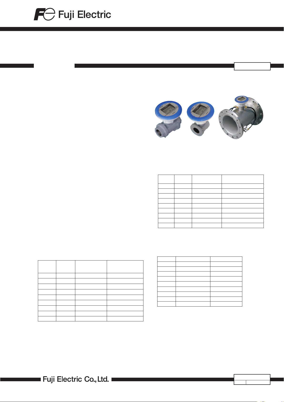
ULTRASONIC FLOW METER FOR AIR
DATA SHEET
FWD is an ultrasonic flow meter that measures flow rate
of the air or nitrogen gas in pipes from 25mm to 200mm.
As a Air flow meter it is ideal for management of the
operating load rate of the compressor, management of
the amount of the used air in the factory and detecting of
the air leakage in the factory.
FEATURES
1. No pressure loss
Ultrasonic measurement involves no obstructions inside the measuring pipe, so there is no pressure loss.
2. Strong resistance to oil and vapor
No moving parts means high resistance to fluids containing oil, vapor, and dust.
3. Battery-powered
The built-in battery type (with a life of 10 years) makes
power line construction unnecessar y.
The external power supply type (24V DC) is also available.
4. Wide rangeability 1:60
The wide rangeability allows for accurate measurement
of even smaller flow rates.
5. Various output functions
Unit pulse, 4 to 20mA DC, upper/lower limit alarm,
device error alarm
SPECIFICATIONS
Nominal diameter (mm):
25, 32, 40, 50, 65, 80, 100, 150, 200
Flow-rate range:
(Actual flow) (Accuracy guarantee range)
Type
FWD025 25mm ±0.6 to ±35 ±3.6 to ±210
FWD032 32mm ±1.1 to ±65 ±6.5 to ±390
FWD040 40mm ±1.3 to ±80 ±7.7 to ±470
FWD050 50mm ±2.5 to ±150 ±15.0 to ±890
FWD065 65mm ±4.0 to ±240 ±24.0 to ±1420
FWD080 80mm ±5.0 to ±300 ±30.1 to ±1780
FWD100 100mm ±10 to ±500 ±59 to ±2970
FWD150 150mm ±24 to ±1200 ±140 to ±7120
FWD200 200mm ±40 to ±2000 ±240 to ±11870
* This column shows flow rates converted into the normal flow rates
(flow rates at 0°C and 1 atm), assuming the measurement is carried
out under a temperature of 0°C and a pressure of 0.5 MPa.
Nominal
diameter
Flow-rate range
3
/h)
(m
[Reference]
NORMAL
flow rate (m
3
/h)*
FWD
40 to 80mm 100 to 200mm25, 32mm
Accuracy:
(Actual flow)
Nominal
Type
diameter
FWD025 25mm ±0.6 to ±3.5m
FWD032 32mm ±1.1 to ±6.5m
FWD040 40mm ±1.3 to ±8m
FWD050 50mm ±2.5 to ±15m
FWD065 65mm ±4.0 to ±24m
FWD080 80mm ±5.0 to ±30m
FWD100 100mm ±10 to ±50m
FWD150 150mm ±24 to ±120m
FWD200 200mm ±40 to ±200m
NORMAL conversion accuracy (accuracy of flow rates converted into
the ones under “normal” conditions):
FWD025…FWD080: ±2.5% of rate (at 0.5 MPa, 25°C, dry air)
FWD100…FWD200: ±2.0% of rate (at ≥ 300 kPa)
Low flow cut-off:
(Actual flow)
Type Nominal diameter Low flow cut-off
FWD025 25mm ±0.1m
FWD032 32mm ±0.2m
FWD040 40mm ±0.2m
FWD050 50mm ±0.4m
FWD065 65mm ±0.6m
FWD080 80mm ±0.8m
FWD100 100mm ±2.6m
FWD150 150mm ±5.0m
FWD200 200mm ±9.0m
Update rate:
0.5 seconds (2 seconds for Built-in battery type)
Calculates the moving average of instantaneous
flow rates (default setting: a set of four measurements)
Flow rate conversion:
Normal flow rate:
a flow rate converted into the one under the
conditions of 0°C and 1 atm.
Standard flow rate:
a flow rate converted into the one at the userdefined temperature and 1 atm.
±5% of rate ±2% of rate
3
/h over ±3.5 to ±35m3/h
3
/h over ±6.5 to ±65m3/h
3
/h over ±8 to ±80m3/h
3
/h over ±1 to ±150m3/h
3
/h over ±24 to ±240m3/h
3
/h over ±30 to ±300m3/h
3
/h over ±50 to ±500m3/h
3
/h over ±120 to ±1200m3/h
3
/h over ±200 to ±2000m3/h
3
/h or less
3
/h or less
3
/h or less
3
/h or less
3
/h or less
3
/h or less
3
/h or less
3
/h or less
3
/h or less
EDS6-146b
Sep. 29, 2017Date
...
2
Page 2

FWD
...
2
Unit:
Accumulated flow rate: m
Instantaneous flow rate: L/min, m
3
, L
3
/h
Pressure: kPa
Temperature: °C
Note: Flow rates are indicated in either form of the actual
flow rate or the converted flow rate, and the latter
is further divided into the normal flow rate and the
standard flow rate. For their definitions, see “flow
rate conversion” on Page 1. The factor y default
setting for flow rate indication is Normal flow rate.
Display: You can change the indication mode and display
contents by using buttons.
• Main display:
[Forward Flow Indication Mode]
Forward flow accumulated volume (Total) (m
Forward flow accumulated volume (Trip) (m
3
3
Instantaneous flow-rate (L/min).
[Reverse Flow Indication Mode]*
Forward flow accumulated volume (Total) (m
Reverse flow accumulated volume (Total) (m
3
3
Instantaneous flow-rate (L/min)
• Sub display:
Instantaneous flow-rate (m
3
/h) · Pressure (kPa)·
Temperature (°C)
* If you set the instantaneous flow rate for the main
display, the sub display will be blank.
<When pipe size is 25 to 80mm>
Display digits:
• Main display
Forward flow accumulated volume (Total):
000 00000.0 (m
Forward flow accumulated volume (Trip):
000 0000.0 (m
Reverse flow accumulated volume (Total):
-0000000.0 (m
3
) 9 digits
3
) 8 digits
3
) 8 digits
Instantaneous flow-rate:
000 00.00 (L/min) 7 digits
Note) In case of selection of Actual Flow Indication
3
(m
) at “Forward flow accumulated volume (Total)”, “Forward flow accumulated volume (Trip)”
“Reverse flow accumulated volume (Total)”, 2
digits after the decimal point are to be indicated.
• Sub display:
Instantaneous flow-rate:
000.00 (< 10000) 5 digits
000 00 (≥ 10000) 5 digits
3
Unit: m
/h
Pressure: 0000.0 (kPa) 5 digits
Temperature: 00.0 (°C) 3 digits
<When pipe size is 100 to 200mm>
Display digits:
• Main display
Forward flow accumulated volume (Total):
000 000000 (m
Forward flow accumulated volume (Trip):
000 00000 (m
Reverse flow accumulated volume (Total):
-00000000 (m
3
) 10 digits
3
) 9 digits
3
) 9 digits
Instantaneous flow-rate:
000 0000 (L/min) 7 digits
• Sub display:
Instantaneous flow-rate:
000 0.0 (< 10000) 5 digits
000 00 (≥ 10000) 5 digits
3
Unit: m
/h
Pressure: 0000.0 (kPa) 5 digits
Temperature: 00.0 (°C) 3 digits
Current output: 4 to 20mA DC (Unavailable for the built-in
battery type)
Current output accuracy: ±0.5%FS
Load resistance: 400Ω or less
(Changeover of ”Instantaneous flow-rate”, “Pressure”,
“Temperature” is available with button operation)
The following is an example when you selected the
instantaneous flow rate.
<Forward flow indication mode>
Zero output current: 4mA (Reverse flow or low flow)
Output current lower limit: 4mA
Output current higher limit: 22mA
<Reverse flow indication mode>
Zero output current: 12mA (Within low flow cut-off)
Output current lower limit: 2mA
)·
)·
)·
)·
Output current higher limit: 22mA
Full scale flow-rate:
Type Nominal diameter
FWD025 25mm 300
FWD032 32mm 600
FWD040 40mm 700
FWD050 50mm 1200
FWD065 65mm 2000
FWD080 80mm 2500
FWD100 100mm 5000
FWD150 150mm 10000
FWD200 200mm 20000
(The above indicated are the default values. You can
change them by button operation.)
Initial setting value
(m
Contact pulse output: (Unavailable for the built-in battery
type)
Open drain output: 2 outputs
Output 1: Unit pulse output (forward flow)
Output 2:
Unit pulse output (reverse flow), or Flow-rate
upper/lower alarm output.
Maximum Load: 24V DC, 50mA
Saturation voltage at ON: 1.5V or less
Current at OFF: 50μA or less
Pulse output
Output of unit pulses corresponding to increase
of accumulated flow
Pulse unit (initial setting): 100 L/P (25 to 80mm)
3
1 m
/P (100 to 200mm)
Maximum output frequency: 10 Hz
Duty: 35 to 65% or One shots (50, 100, 125,
250, 500ms)
Flow-rate upper/lower alarm
An alarm signal is emitted when the flow rate
reaches user-defined upper limit or lower limit.
You can also define the alarm hysteresis.
Fluid to be measured:
Air (mainly factory air, compressor air) or nitrogen
(not available for 100 to 200mm.)
Fluid temperature:
-10 to +60°C, 90%RH or less
Working pressure:
0 to 1MPa (gauge pressure)
Ambient conditions:
-10 to +60°C, 90%RH or less (No dew condensation)
Storage ambient conditions:
-20 to +70°C (No dew condensation)
3
/h)
2
Page 3

Power supply:
• 24VDC±10%,
Power consumption:
1.5W Maximum (Current consumption: 40mA
maximum)
• Built-in lithium batter y (battery life is 10 years under ar
ambient temperature of 20°C)
Flow direction:
forward or reverse (Direction indicated by the
arrow mark is regarded as forward flow)
Connection method:
1) Nominal diameter 25mm
Rc1
2) Nominal diameter 32mm
Rc 1-1/4
3) Nominal diameter 40mm to 80mm
Wafer connection (Installation between JIS10K
flanges and by tightening with bolts)
4) Nominal diameter 100mm to 200mm
JIS10K flange
Installation position:
Horizontal (LCD display is to face upwards) or
vertical
Pressure drop:
Negligible (Equivalent to a straight pipe)
Protection structure:
IP64 (JIS C0920: Dust-proof, splash-proof type),
Possible to inst all outdoor
Weight: Refer to “Oultine diagrams”.
Materials:
◦Outer casing:
Aluminum alloy
◦Measurement pipe:
Aluminum alloy (25 to 80mm dia.)
Stainless alloy (100 to 200mm dia.)
◦Sensor holder:
PPS
◦Sensor rubber:
FVMQ (Fluorosilicone rubber)
Display casing:
Aluminum alloy
*Those marked with ◦ are the parts contact with fluid.
Installation Requirements
• Add a sunshade for the flowmeter if it is exposed to
direct sunlight.
• Avoid places where:
- the electromagnetic noise level is high
- the atmosphere is corrosive
- there is a risk of submersion
- the flowmeter constantly gets wet
EU Directive Compliance
EMC (2014/30/EU)
EN 61326-1
RoHS (2011/65/EU)
EN 50581
PED (2014/68/EU)
*Applicable to FWD150 and FWD200 only
EN 10216-5
CODE SYMBOLS
FWD
Digit
4
5
6
7
8
9
10
11
Note1)
from 25 to 80 mm.
Note2)
“none “(code “0”) in the 10th digit.
Accessories
Nominal diameter Accessory
25, 32mm M4 Hexagonal wrench
40, 50, 65, 80mm
Flange gaskets, Bolt set
100, 150, 200mm
Specifications Note
<Nominal diameter(mm)>
25
32
40
50
65
80
100
150
200
<Power supply>
24V DC
Build-in Battery
Modification No.
<Fluid to be measured>
Air
Nitrogen
<Power cable>
None
5m
20m
<Instruction Manual>
None
Japanese
English
Applicable pipe diameters for nitrogen measurement are
If you select the built-in battery type (7th code “B”), select
M4 Hexagonal wrench, Center adjusting collar,
M4 Hexagonal wrench, Center adjusting collar
0
0
0
0
0
0
1
1
2
Note1
Note2
7 8 9 10 114 5 6
2
5
2
2
3
0
4
0
5
5
6
0
8
0
0
0
5
0
0
D
B
2
A
N
0
5
2
0
1
2
Piping Requirements
• It is recommended to secure at least 10D (D: diameter)
straight pipe run both on upstream and downstream of
the flowmeter.
• If the fluid contains a large amount of mist and/or dust,
install the flowmeter on vertical piping.
3
Page 4

...
FWD
2
OUTLINE DIAGRAMS (Unit : mm)
Screw-in type
<Nominal diameter: 25,32mm>
Wafer connection type
<Nominal diameter: 40 to 80mm>
130
144
162
20 20
147
Type Mass. (kg)
FWD025 1.7
FWD032 1.6
JIS10K pipe flange type
<Nominal diameter: 100to 200mm>
t
JIS10K Flange
80
Rc1 (FWD025)
Rc1・1/4 (FWD032)
58
(Octagon)
130
144
H
W
øD
Type W H øD Mass. (kg)
FWD040 76 163 81 1.1
FWD050 90 176 96 1.3
FWD065 108 197 117 1.6
FWD080 117 220 126 1.8
CONNECTION DIAGRANS (External power supply type)
Connector
Flow meter
Shield cable
White
Open drain output 1:
Unit pulse (Forward flow)
Yellow
Open drain output 2:
Unit pulse (Reverse flow),
flow-rate upper/lower limit alarm
Red
Power supply (24V DC)
Integrator
load
Integrator, exc.
load
Note Note
H
W
Type W H øD øC t n øh
øD
øC
n-øh
Mass. (kg)
FWD100 250 280 210 175 18 8 19 10.0
FWD150 300 341 280 240 22 8 23 18.3
FWD200 350 391 330 290 22 12 23 24.1
Caution on Safety
*Before using this product, be sure to read its instruction manual.
Global Sales Section
Instrumentation & Sensors Planning Dept.
1, Fuji-machi, Hino-city, Tokyo 191-8502, Japan
http://www.fujielectric.com
Phone: +81-42-514-8930 Fax: +81-42-583-8275
http://www.fujielectric.com/products/instruments/
Information in this catalog is subject to change without notice.
Green
Black
Note) Power supply is not required if the
integrators have their power source.
4 to 20mA DC
E
+
Receving
instrument
−
Printed i n Ja pan
 Loading...