

Fuji Electric FVR0.75AS1S-4, FVR-Micro, FVR0.4AS1S-4, FVR1.5AS1S-4, FVR2.2AS1S-4 Brief Manual
...Page 1
Advanced simple Inverter
FVR-Micro
Thank you for purchasing our FVR-Micro of inverters.
This product is designed to drive a three-phase induction motor. Read through this
instruction manual and be familiar with the handling procedure for correct use.
Improper handling might result in incorrect operation, a short life, or even a failure of this
product as well as the motor.
Deliver this qui ck guide to the end user of this product. Keep this in a safe place until this
product is discarded.
For more details, refer to the instruction manual on website.
Web site : https://felib.fujielectric.co.jp/download/search.htm?site=global&lang=en
QR code :
Fuji Electric Co., Ltd. INR-SI47-2142a-E
Brief Manual
Page 2
Safety precautions
Read this manual thoroughly before proceeding with installation, connections (wiring), operation, or
maintenance and inspection. Ensure you have sound knowledge of the device and familiarize
yourself with all safety information and precautions before proceeding to operate the inverter.
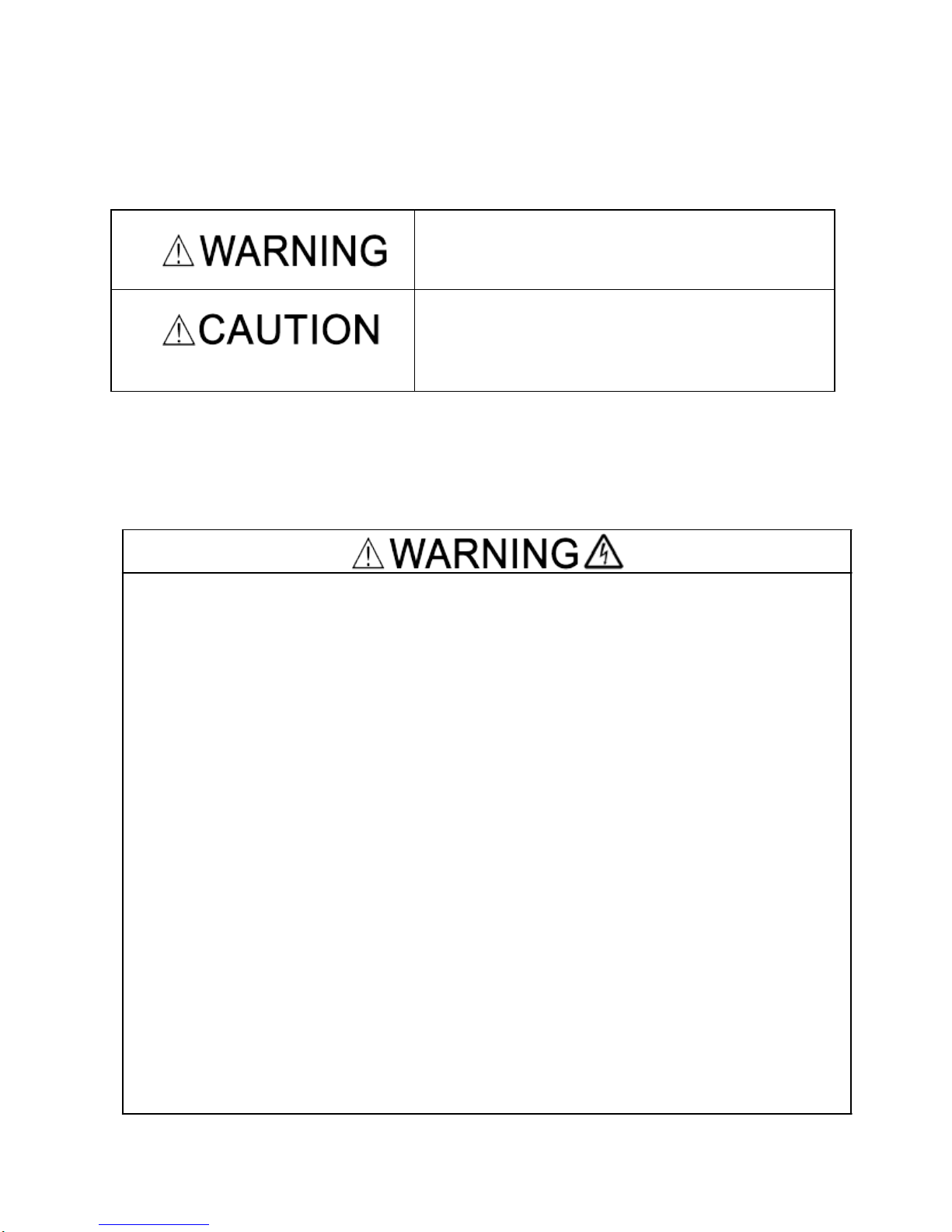
Safety precautions are classified into the following two categories in this manual.
Failure to heed the information indicated by this
symbol may lead to dangerous conditions, possibly
resulting in death or serious bodily injuries.
Failure to heed the information indicated by this
symbol may lead to dangerous conditions, possibly
resulting in minor or light bodily injuries and/or
substantial property damage.
Failure to heed the information contained under the CAUTION title can also resu lt in s erious consequences. These safety precautions are of utmost importance and must be observed at all times.
Operation
Be sure to install the terminal block cover before turning the power on. Do not remove the
cover while power is applied.
Otherwise electric shock could occur.
Do not operate switches with wet hands.
Doing so could cause electric shock.
If the retry function has been selected, the inverter may automatically restart and drive
the motor depending on the cause of tripping.
(Design the machinery or equipment so that human safety is ensured after restarting.)
If the stall prevention function (current limiter), automatic deceleration, and overload
prevention control have been selected, the inverter may operate at an acceleration
/deceleration time or frequency different from the set ones. Design the machine so that
safety is ensured even in such cases.
Otherwise an accident could occur.
The STOP key is only effective when function setting (Function code F02) is established
to enable the STOP key. Prepare an emergency stop switch separately. If you disable
the STOP key priority function and enable operation by external commands, you cannot
emergency-stop the inverter using the STOP key on the built-in keypad.
If an alarm reset is made with the operation signal turned on, a sudden start will occur.
Ensure that the operation signal is turned off in advance.
Otherwise an accident could occur.
1
Page 3
Item
Specifications
Site location Indoors
Ambient
temperature
-10 to +50°C (IP20) (Note 1)
Relative
humidity
5 to 95% (No condensation)
Atmosphere
The inverter must not be exposed to dust,
direct sunlight, corrosive gases, flammable
gas, oil mist, vapor or water drops.
(Note 2)
The atmosphere can contain only a low
level of salt.
(0.01 mg/cm
2
or less per year)
The inverter must not be subjected to
sudden changes in temperature that will
cause condensation to form.
Altitude 1,000 m max. (Note 3)
Atmospheric
pressure
86 to 106 kPa
Vibration
3 mm (Max. amplitude) 2 to less than 9 Hz
9.8 m/s
2
9 to less than 20 Hz
2 m/s
2
20 to less than 55 Hz
1 m/s
2
55 to less than 200
Hz
1. Operating Environment
Install the inverter in an environment that satisfies the requirements listed in
Table 1.1 Environmental Requirements
Table 1.2 Output Current Derating Factor
in Relation to Altitude
2. Installing the Inverter
(1) Mounting base
The temperature of the heat sink may rise up to
approx. 90°C during operation of the inverter, so the
inverter should be mounted on a base made of
material that can withstand temperatures of this
level.
Install the inverter on a base made of metal or
other non-flammable material.
A fire may result with other material.
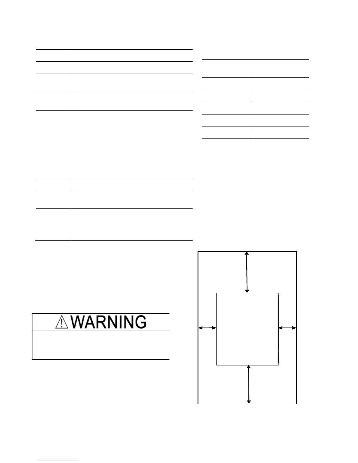
(2) Clearances
Ensure that the minimum clearances indicated in
Figure 2.1 are maintained at all times. When
installing the inverter in the panel of your system,
take extra care with ventilation inside the panel as
the temperature around the inverter tends to
increase.
Figure 2.1 Mounting Direction and
Required
Clearances
Altitude
Output current
derating factor
1000 m or lower
1.00
1000 to 1500 m
0.97
1500 to 2000 m
0.95
2000 to 2500 m
0.91
2500 to 3000 m
0.88
(Note 1)
When inverters are mounted side-by-
side without any gap between them, the
ambient temperature should be within the
range from -10 to +40°C.
(Note 2)
Do not install the inverter in an
environment where it may be exposed to
cotton waste or moist dust or dirt which will
clog the heat sink in the inverter. If the
inverter is to be used in such an
environment, install it in the panel of your
system or other dustproof containers.
(Note 3)
If you use the inverter in an altitude
above 1000 m, you should apply an output
current derating factor as listed in Table 2.2.
Left
10 mm
Right
10 mm
Bottom 100 mm
FVR-Micro
Top 100 mm
2
Page 4
When mounting two or more inverters
When mounting two or more inverters in the same unit or panel, basically lay them out s ide by
side. As long as the ambient temperature is 40°C or lower, inverters can be mounted side by
side without any clearance between them. When the inverters necessarily mounted one above
the other be sure to separate them with a partition plate or the like so that any heat radiating
from an inverter will not affect the one(s) above.
(3) Mounting direction
Secure the inverter to the mounting base with four screws or bolts (M4) so that the FVR-Micro logo
faces outwards. (FVR0.4AS1S-7 and
FVR0.75AS1S-7 use t wo screws or bolts.) Tighten those
screws or bolts perpendicular to the mounting base. (Maximum torque is 0.6N∙m)
Do not mount the inverter upside down or horizontally. Doing so will reduce the
heat dissipation efficiency of the inverter and cause the overheat protection function to
operate, so the inverter will not run.
Prevent lint, paper fibers, sawdust, dust, metallic chips, or other foreign materials from getting
into the inverter or from accumulating on the heat sink.
This may result in a fire or accident.
3. Wiring
Follow the procedure below. (In the following description, the inverter has already been installed.)
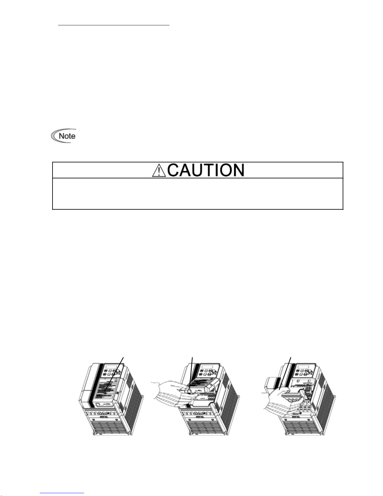
3.1 Removing and mounting the terminal block covers
(1) Loosen the screw securing the control circuit terminal block cover.
(2) Insert your finger in the cutout (near "PULL") in the bottom of the control circuit terminal
block cover, and then pull the cover towards you.
(3) Hold both sides of the main circuit terminal block cover between thumb and forefinger and
slide it towards you.
(4) After performing wiring, mount the main circuit terminal block cover and control circuit
terminal block cover in the reverse order of removal.
[ Removing the Terminal Block Covers ]
Control circuit terminal
block cover screw
Control circuit terminal
block cover
Main circuit terminal
block cover
3
Page 5
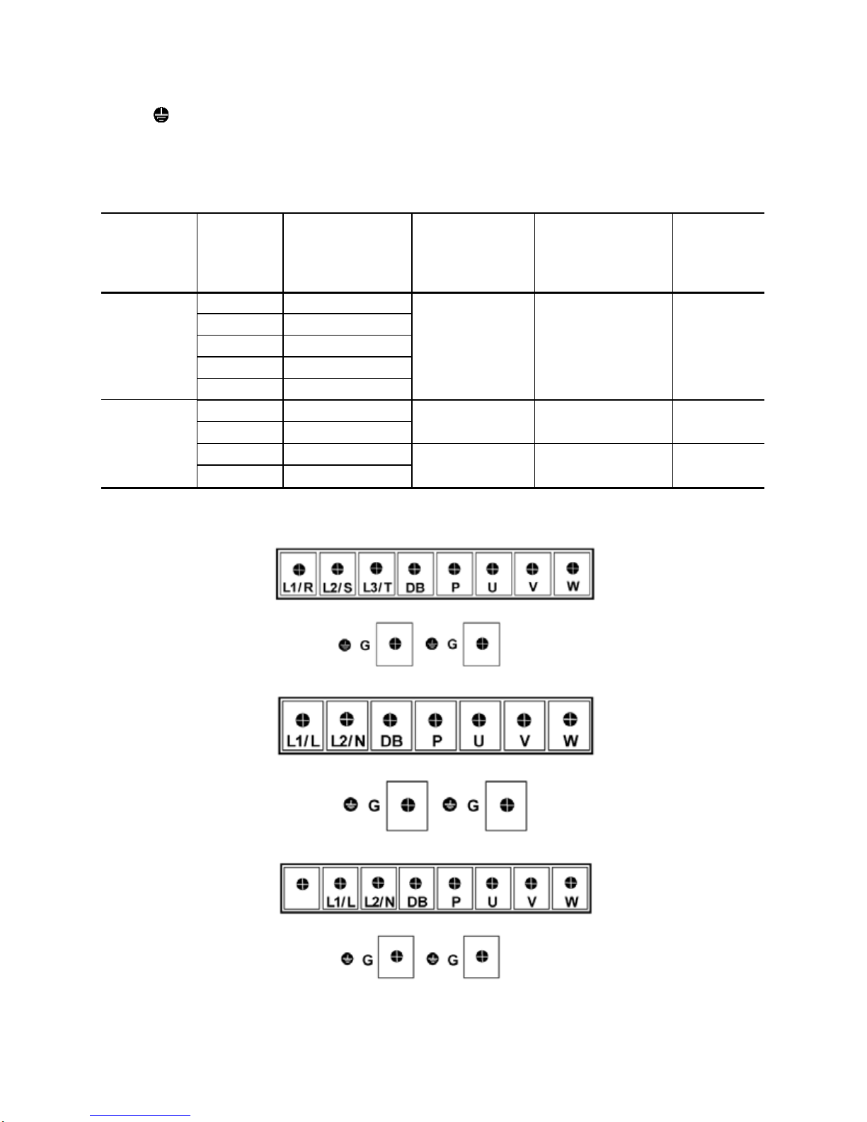
3.2 Terminal arrangement and screw specifications
The figures below show the arrangement of the main and control circuit terminals which differ
according to inverter type. The two terminals prepared for grounding, which are indicated by the
symbol G in Figures A to C, make no distinction between the power supply side (primary circuit)
and the motor side (secondary circuit).
(1) Arrangement of the main circuit terminals
Table 3.1 Main Circuit Terminals
Power supply
voltage
Nominal
Ap
plied
m
otor(kW)
Inverter type
Terminal screw
size
Tightening torque
(N·m)
Refer to:
Three- phase
400 V
0.4
FVR0.4AS1S-4
M4 1.2 Fig A
0.75
FVR0.75AS1S-4
1.5
FVR1.5AS1S-4
2.2
FVR2.2AS1S-4
3.7
FVR3.7AS1S-4
Single- phase
200 V
0.4
FVR0.4AS1S-7
M3 0.5 Fig B
0.75
FVR0.75AS1S-7
1.5
FVR1.5AS1S-7
M4 1.2 Fig C
2.2
FVR2.2AS1S-7
Figure A
Figure B
Figure C
4
Page 6
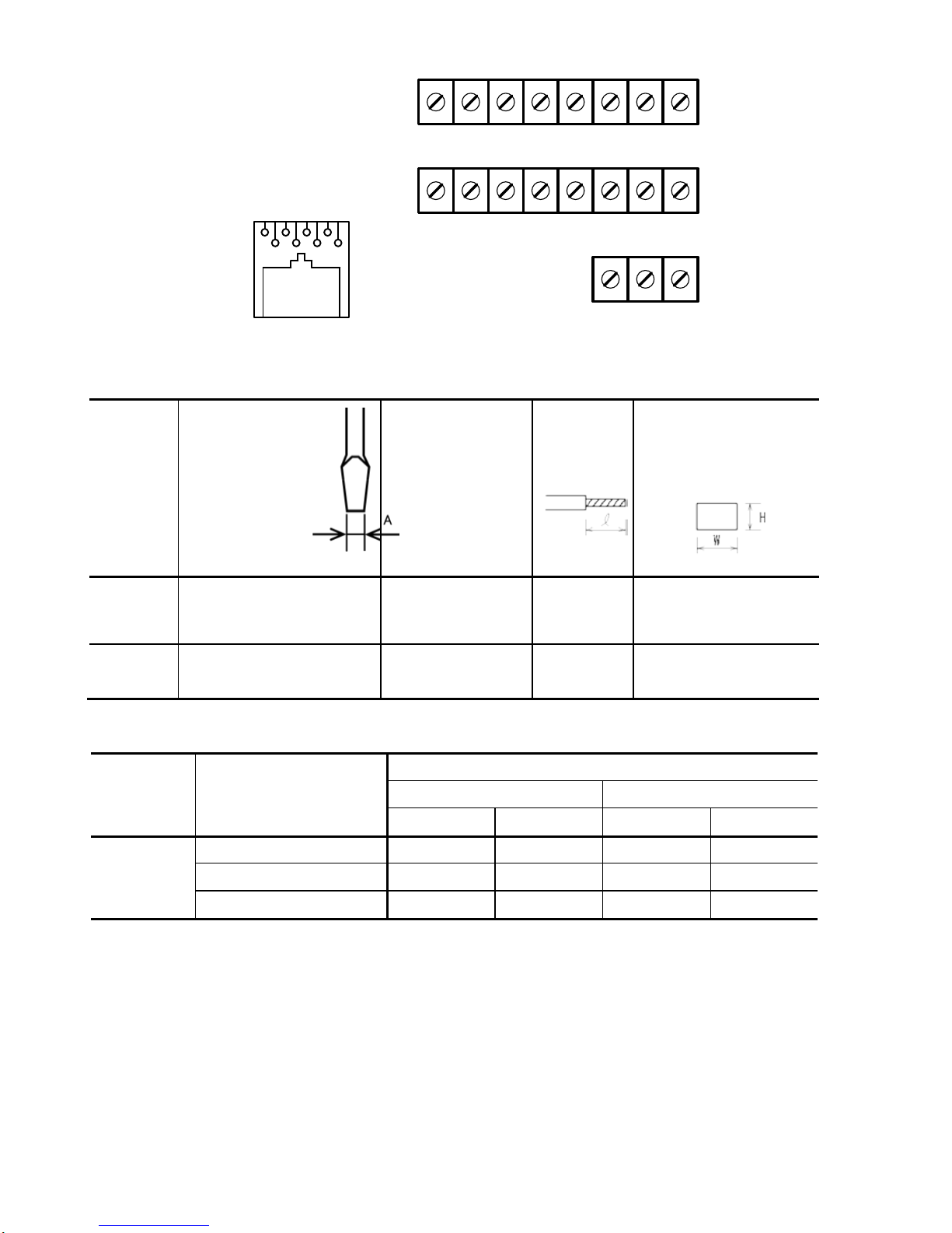
(2) Arrangement of the control circuit termi nal s (c om m on to all FVR-Micro models)
Y1 Y1E FMA C1 PLC X1 X2 X3
DX+ DX- 13 12 11 FWD REV CM
30A 30B 30C
8 7 6 5 4 3 2 1
1 : 5V
2 : Ground
3 : NC
4 : DX5 : DX+
6 : NC
7 : Ground
8 : 5V
Screw size : M2.5 Tightening torque : 0.4Nm
Table 3.2 Control Circuit Terminals
Terminal
symbol
Screwdriver
(Shape of
tip,
B x A)
Thickness of tip: B
Allowable wire size
Bare wire
length
Ferrule
terminal*
Opening dimension in
the terminal
block
First row in
the box
[Y1]~[X3]
Flat screwdriver
(0.6 x 3.5 mm)
AWG22 to AWG14
(0.34 to 2.1 mm
2
)
4.5 to 5 mm 5 (W) x 2.5 (H) mm
Other than
the above
Flat screwdriver
(0.6 x 3.5 mm)
AWG24 to AWG14
(0.25 to 2.1 mm
2
)
5 to 6 mm 2.3 (W) x 2.5 (H) mm
Table 3.3 Recommended Ferrule Terminals
Screw size Wire
size
Type
(216- )
With insulated collar Without insulated collar
Short type Long type Short type Long type
M2 or M2.5
AWG22 (0.34 mm2 )
322 302 152 132
AWG20 (0.50 mm2 )
221
201
121
101
AWG18 (0.75 mm2 )
222 202 122 102
The length of bared wires to be inserted into ferrule terminals is 5.0 mm or 8.0 mm for the short
or long type, respectively.
The following crimping tool is recommended: Variocrimp 4 (Part No. 206-204).
5
Page 7
3.3 Recommended wire sizes
Table 2.6 lists the recommended wire sizes. The recommended wire sizes for the main circuit
terminals for an ambient temperature of 50°C are indicated for two types of wire: HIV single wire (for
the maximum allowable temperature 75°C).
Table 3.4 Recommended Wire Sizes
Power supply
voltage
Nomi-
nal
applied
motor
(kW)
Inverter type
*1
Recommended wire size (mm
2
)
Main
Control
circuit
Main circuit power
input
[L1/R, L2/S, L3/T]
[L1/L,
L2/N]
Grounding
[ G]
Inverter
output
[U, V, W]
Braking
resistor
[P, DB]
w/o DCR
Three-phase
400 V
0.4
FVR0.4AS1S-4
2.0(2.0)
0.5
0.75
FVR0.75AS1S-4
1.5
FVR1.5AS1S-4
2.2
FVR2.2AS1S-4
3.7
FVR3.7AS1S-4
Single-phase
200 V
0.4
FVR0.4AS1S-7
2.0(2.0)
2.0(2.0)
2.0(2.5)
0.75
FVR0.75AS1S-7
1.5
FVR1.5AS1S-7
2.0(3.5)
2.2
FVR2.2AS1S-7
5.5(5.5)
*1 Use crimp terminals covered with an insulated sheath or insulating tube. Recommended wire sizes are for
HIV/IV (PVC in the EU).
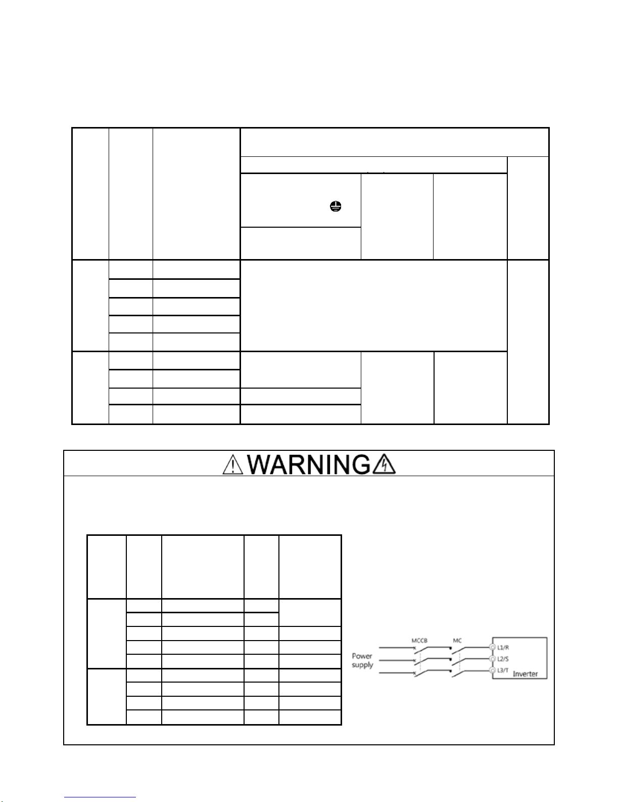
To prevent the risk of hazardous accidents that could be caused by damage of the inverter,
install the specified MCCB in the supply side (primary side) according to the following tables.
- Breaking capacity: Min. 10 kA
- Rated voltage: Min. 500 V
Power
supply
voltage
Appli-
cable
motor
rating
(kW)
Inverter type
Fuse
Rating
(A)
Rated
Current(A)
of MCCB
(w/o DCR)
Three-
phase
400 V
0.4
FVR0.4AS1S-
4
3
6
0.75
FVR0.75AS1S
-4
6
1.5
FVR1.5AS1S
-4
10
10
2.2
FVR2.2AS1S
-4
15
15
3.7
FVR3.7AS1S
-4
20
20
Single-
phase
200 V
0.4
FVR0.4AS1S
-7
10
10
0.75
FVR0.75AS1S
-7
15
15
1.5
FVR1.5AS1S
-7
30
20
2.2
FVR2.2AS1S
-7
40
35
6
Page 8
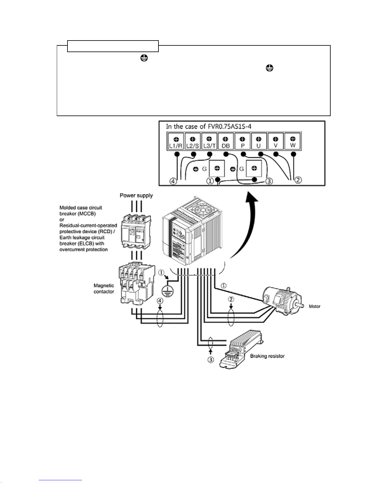
3.4 Wi ring for main circuit terminals and grounding terminals
Follow the procedure below. Figure 3.1 illustrates the wiring procedure with peripheral equipment.
Wiring procedure
①
Grounding terminal G*
1
② Inverter output terminals (U, V, and W) and grounding terminal G*1
③ Braking resistor connection terminals (P and DB)*2
④ Main circuit power input terminals (L1/R, L2/S and L3/T) or (L1/L and L2/N)
*
1
Use either one of these two grounding terminals on the main circuit terminal block.
*
2
Perform wiring as necessary.
Figure 3.1 Wiring procedures for Peripheral Equipment
7
Page 9
The wiring procedure for the FVR0.75AS1S-4 is given below as an example. For other inverter
types, perform wiring in accordance with their individual terminal arrangement.
①
Grounding terminal ( G)
Be sure to ground either of the two grounding terminals for safety and noise reduction. It is
stipulated by the Electric Facility Technical Standard that all metal frames of electrical equipment
must be grounded to avoid electric shock, fire and other disasters.
Grounding terminals should be grounded as follows:
1) Ground the inverter in compliance with the national or local electric code.
2) Connect a thick grounding wire with a large surface area. Keep the wiring length as short as
possible.
②
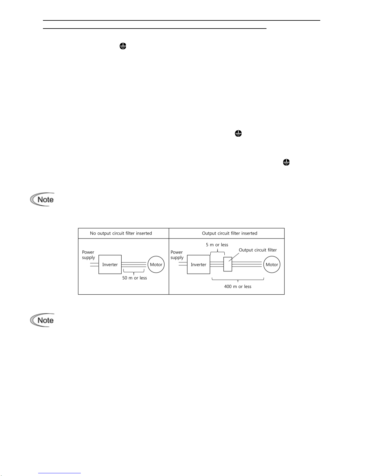
Inverter output terminals, U, V, W and grounding terminal ( G)
1) Connect the three wires of the three-phase motor to terminals U, V, and W, aligning phases
each other.
2) Connect the grounding wire of terminals U, V, and W to the grounding terminal ( G).
The wiring length between the inverter and motor should not exceed 50 m. If it exceeds
50 m, it is recommended that an output circuit filter (option) be inserted.
Do not use one multicore cable to connect several inverters with motors.
Do not connect a phase-advancing capacitor or surge absorber to the inverter’s output
lines (secondary circuit).
If the wiring length is long, the stray capacitance between the wires will increase,
resulting in an outflow of the leakage current. It will activate the overcurrent protecti on,
increase the leakage current, or will not assure the accuracy of the current display. In
the worst case, the inverter could be damaged.
If more than one motor is to be connected to a single inverter, the wiring length should
be the total length of the wires to the motors.
8
Page 10

Driving 400 V series motor
If a thermal relay is installed in the path between the inverter and the motor to protect
the motor from overheating, the thermal relay may malfunction even with a wiring
length shorter than 50 m. In this situation, add an output circuit filter (option) or lower
the carrier frequency (Function code F26: Motor sound (Carrier frequency)).
If the motor is driven by a PWM-type inverter, surge voltage that is generated by
switching the inverter component may be superimposed on the output voltage and may
be applied to the motor terminals. Particularly if the wiring length is long, the surge
voltage may deteriorate the insulation resistance of the motor. Consider any of the
following measures.
- Use a motor with insulation that withstands the surge voltage.
- Connect an output circuit filter (option) to the output terminals (secondary circuits) of
the inverter.
- Minimize the wiring length between the inverter and motor (10 to 20 m or less).
③
Braking resistor terminals, P and DB
1) Connect terminals P and DB of a braking resistor (option) to terminals P and DB on the main
circuit terminal block.
2) Arrange the inverter and braking resistor to keep the wiring length to 5 m or less and twist the
two wires or route them together in parallel.
④
Main circuit power input terminals, L1/R, L2/S, and L3/T ( for thre e-phase volta ge input) or
L1/L and L2/N (for single-phase voltage i nput )
1) For safety, make sure that the molded case circuit breaker (MCCB) or magnetic contactor
(MC) is turned off before wiring the main circuit power input terminals.
2) Connect the main circuit power supply wires (L1/R, L2/S and L3/T or L1/L and L2/N) to the
input terminals of the inverter via an MCCB or residual-current-operated protective device
(RCD)/earth leakage circuit breaker (ELCB)*, and MC if necessary.
It is not necessary to align phases of the power supply wires and the input terminals of the
inverter with each other.
* With overcurrent protection
It is recommended that a magnetic contactor be inserted which can be manually
activated.
This is to allow you to disconnect the inverter from the power supply in an emergency
(e.g., when the protective function is activated) so as to prevent a failure or accident
from causing the secondary problems.
9
Page 11

4. Names and Functions of Keypad Components
As shown in the figure at right, the
keypad consists of a four-digit 7-segment
LED monitor, a potentiometer (POT), and
six keys.
The keypad allows you to start and stop
the motor, monitor running status,
configure the function code data, check
I/O signal states, and display
maintenance information and alarm
information.
Table 4.1 Names and Functions of Keypad Components
Monitor,
Potentiometer
and
Keys
Functions
Four-digit, 7-segment LED monitor which displays the following according to the
operation modes *.
In Running mode: Running status information (e.g., output frequency,
current, and
voltage)
In Programming mode: Menus, function codes and their data
In Alarm mode: Alarm code which identifies the error factor if the
protective function is activated.
Potentiometer (POT) which is used to manually set a reference frequency, auxiliary
frequencies 1 and 2 or PID process command.
RUN key. Press this key to run the motor.
STOP key. Press this key to stop the motor.
UP/DOWN keys. Press these keys to select the settin g items and change the function
code data displayed on the LED monitor.
Program/Reset key which switches the operation modes* of the inverter.
In Running mode: Pressing this key switches the inverter to Programming mode.
In Programming mode: Pressing this key switches the inverter to Running
mode.
In Alarm mode: Pressing this key after removing the error factor
switches the inverter to Running mode.
Function/Data key which switches the operation you want to do in each mode as
follows:
In Running mode: Pressing this key switches the information to be displayed
concerning the status of the inverter (output freque ncy, output current, output voltage,
etc.).
In Programming mode: Pressing this key displays the function codes and sets their data
entered with the and keys or the POT.
In Alarm mode: Pressing this key displays detailed alarm information.
* FVR-Micro features three operation modes: Running, Programming, and Alarm.
10
Page 12

5. If an Alarm Code Appears on the LED Monitor
Quick reference table of alarm codes
Alarm
code
Name
Alarm
code
Name
OC1
Instantaneous overcurrent
dbH
Braking resistor overheated
OC2 OL1
Motor 1 overload
OC3 OLU
Inverter overload
OU1
Overvoltage
Er1
Memory error
OU2 Er2
Keypad communications error
OU3 Er3
CPU error
LU
Undervoltage
Er6
Operation protection
Lin
Input phase loss
Er7
Tuning error
OPL
Output phase loss
Er8
RS-485 communications error
OH1
Heat sink overheat
ErF
Data saving error during
under voltage
OH2
External alarm
Err
Mock alarm
OH4
Motor protection
(PTC thermistor)
CoF
PID feedback wire break
11
Page 13

6. Specifications
6.1
Single-phase 200 V class series
Item
Specifications
Type
0.4
0.75
1.5
2.2
Applicable motor rating (kW)
*1
0.4 0.75 1.5 2.2
Output Ratings
Rated capacity (kVA)
*2
0.9 1.6 2.8 3.8
Rated voltage (V) *3
Three-phase, 200 to 240 V (with AVR function)
Rated current (A) *4
3.5 (2.5) 4.2 (4.2) 9.2 (7.5) 10.0 (10.0)
Overload capability
150% of rated output current for 1 min (for the rated current given in
parentheses)
Rated frequency (Hz)
50/60 Hz
Input Ratings
Phases, voltage,
frequency
Single-phase, 200 to 240 V, 50/60 Hz
Voltage and
frequency variations
Voltage: +10 to -10%, Frequency: +5 to -5%
Rated
current(A)
*6
(w/o
DCR)
5.4 9.7 16.4 24.0
Required power
supply capacity (kVA)
0.7 1.3 2.4 3.5
Braking
Torque (%) *8
100
50 30
DC braking
Braking starting frequency*9: 0.0 to 60.0 Hz,
Braking time: 0.0 to 30.0 s, Braking level: 0 to 100%
Braking transistor
Built-in
Applicable safety standards
UL61800-5-1, IEC 61800-5-1(under application)
Enclosure
IP20 (IEC 60529), UL open type (UL50)
Cooling method
Fan cooling
Mass (kg)
0.6
0.6
1.0
1.0
*1 Fuji 4-pole standard motor s
*2 Refers to the rated capacity assuming the rated output voltage as 220 V.
*3 Output voltages cannot exceed the power supply voltage.
*4 The load shall be reduced so that the continuous operating current is the rated current in parentheses or less if
the carrier frequency is set to 3 kHz or above or the ambient temperature exceeds 40°C.
*
5
Interphase voltage unbalance (%)
=
Max. voltage (V) - Min.voltage
(V)
× 67
(Refer to
IEC 61800
- 3)
3 phase average voltage (V)
If this value is 2 to 3%, use an optional AC reactor (ACR).
*6 Refers to the estimated value to apply when the power supply capacity is 500 kVA (inverter capacity x 10 when
the inverter capacity exceeds 50 kVA) and the inverter is connected to the %X = 5% power supply.
*8 Refers to the average braking torque to apply when the motor running alone decelerates from 60 Hz with the
AVR control being OFF. (It varies with the efficiency of the motor.)
*9 Available only for induction motor drive.
12
Page 14

6.2
Three-phase 400 V class series
Item
Specifications
Type
0.4
0.75
1.5
2.2
3.7
Applicable moto r rating (kW)
*1
0.4 0.75 1.5 2.2 3.7
Output Ratings
Rated capacity (kVA)
*2
1.1 1.9 3.2 4.1 6.8
Rated voltage (V ) *3
Three-phase, 380 to 480 V (with AVR function)
Rated current (A )
1.8
(1.5)
2.5
(2.5)
4.3
(4.2)
6.3
(5.5)
10.5
(9.0)
Overload capability
150% of rated outp ut current for 1 min (fo r the rated current given in
parentheses)
Rated frequency ( Hz)
50/60 Hz
Input Ratings
Phases, voltage,
frequency
Three-phase, 380 to 480 V, 50/60 H z
Voltage and
frequency variatio ns
Voltage: +10 to -15% (Interphase voltage unbalance: 2% or less) *5,
Frequency: +5 to -5%
Rated
current (A)
*6
(w/o
DCR)
1.7 3.1 5.9 8.2 13.0
Required power supply
capacity (kVA)
0.6 1.1 2.0 2.9 4.9
Braking
Torque (%) *8
100
50
30
DC braking
Braking starting f requency*9: 0.0 to 60. 0 Hz,
Braking time: 0.0 to 30.0 s, Braking level: 0 to 100%
Braking transistor
Built-in
Applicable safety standards
UL61800-5-1, IEC 61800-5-1 (under application)
Enclosure
IP20 (IEC 60529), UL open type (UL50)
Cooling method
Natural cooling
Fan cooling
Mass (kg)
0.8
0.8
0.9
1.0
1.3
*1 Fuji 4-pole standard motor s
*2 Refers to the rated capacity assuming the rated output voltage as 440 V.
*3 Output voltages cannot exceed the power supply voltage.
*5
Interphase voltage unbalance (%)
=
Max. voltage (V) - Min.voltage
(V)
× 67
(Refer to
IEC 61800
- 3)
3 phase average voltage (V)
If this value is 2 to 3%, use an optional AC reactor (ACR).
*6 Refers to the estimated value to apply when the power supply capacity is 500 kVA (inverter capacity x 10 when the
inverter capacity exceeds 50 kVA) and the inverter is connected to the %X = 5% power supply.
*8 Refers to the average braking torque to apply when the motor running alone decelerates from 60 Hz with the AVR
control being OFF. (It varies with the efficiency of the motor.)
*9 Available only for induction motor drive.
13
Page 15

7. Connection diagram in operation by external signal inputs
Voltage Input
0 to 10 VDC
[Y1]
[Y1E]
[DX+]
Analog input
Analog Meter
[DX-]
Current Input
+4(0) to +20 mADC
[FWD]
[REV]
[CM]
[X1]
[X2]
[X3]
[PLC]
RJ-45
[FMA]
Digital input
[13]
[12]
[C1]
30A
30B
30C
Alarm output
(for any fault)
Transistor Output
Power supply
Single-phase
200 to 240V
50/60Hz
R
[11]
(+)
(-)
3
2
1
Power supply to
potentiometer
RS-485
Communication port
*With a built-in
resistor switch
SINK
SOURCE
L1/L
L2/N
MC (Note 2)
MCCB or
RCD/ELCB
(Note 1)
Control Circuit
Main Circuit
(Note 5)
(Note 6)
ELCB : Earth Leakage Circuit Braker
MC : Magnetic Contactor
MCCB : Molded Case Circuit Braker
RCD : Residual-current- operated
Protective Device
U
V
W
Grounding termical (Note 7)
G
M
Motor
Power supply
Three-phase
380 to 480V
50/60Hz
G
L1/R
L2/S
L3/T
MC (Note 2)
MCCB or
RCD/ELCB
(Note 1)
Grounding termical
P DB
DBR (Dynamic Braking Resistor)
P
DB
2
1
[CM]
[THR]
(Note 4)
(Note 1) Install a recommended molded case circuit breaker (MCCB) or a residual-current-
o
perated protective device (RCD)/earth leakage circuit breaker (ELCB) (with overcurrent
prot
ection) in the primary circuit of the inverter to protect wiring. Do not use an MCCB or
RCD/ELCB whose capacity exceeds the recommended rated current.
(Note 2) A magnetic contactor (MC) should, if necessary, be mounted independent of the MCCB or
ELCB to
cut off the power fed to the inverter. MCs or solenoids that will be installed close to
the inverter require surge absorbers to be connected in parallel to their coils.
(Note 4)
T
he THR function can be used by assigning "9" (External alarm) to any of terminals [X1] to
[X3],[FWD] or [REV] (function code E01 to E03, E98, or E99).
(Note 5)
Frequ
ency can be set by connecting a frequency setting device (external potentiometer)
b
etween terminals [11], [12] and [13] instead of inputting voltage signal (0 to +10 VDC or 0 to
+5VDC) between terminals [12] and [11].
(Note 6)
For the wiring of the control
circuit, use shielded or twisted wires. When shielded wires are
used
, connect the shields to earth. To prevent malfunction due to noise, keep the control
circuit wiring away from the main circuit wiring as far as possible (recommended: 10 cm or
longer),
and never set them in the same wire duct. When crossing the control circuit wiring with
the main circuit wiring, set them at right angles.
14
Page 16

8. External Dimensions
[unit: mm]
[FVR0.4AS1S-7/FVR0.75AS1S-7] [FVR1.5AS1S-7/FVR2.2AS1S-7/
FVR0.4AS1S-4~FVR2.2AS1S-4]
[FVR3.7AS1S-4]
15
Page 17

9. Function Code Tables
Function codes enable the FVR-Micro of inverters to be set up to match your system requirements.
Each function code consists of a 3-letter alphanumeric string. The first letter is an alphabet that
identifies its group and the following two letters are numerals that identify each individual code in the
group. The function codes are classified into seven groups: Fundamental Functions (F codes),
Extension Terminal Functions (E codes), Control Functions (C codes), Motor 1 Parameters (P codes),
High Performance Functions (H codes), Application Functions (J codes) and Link Functions (y
codes). To determine the property of each function code, set data to the function code.
(This manual only shows F functions, refer to the instruction on website for more functions,)
Changing, validating, and saving function code data when the motor is running
Function codes are indicated by the following based on whether they can be changed or not when the
inverter is running:
Notation Change when running Validating and saving function code data
Y*
Possible
If the data of the codes marked with Y* is changed, the change
will immediately take effect; however, the change is not saved
into the inverter's memory. To save the change, press the
(Function/Data) key. If you press the (Program/Reset) key
without pressing the (Function/Data) key to exit the current
state, then the changed data will be discarded and the pre vious
data will take effect for the inverter operation.
Y
Possible
The data of the codes marked with Y can be changed with the
or keys regardless of whether the motor is running or not.
Pressing the (Function/Data) key will make the change
effective and save it into the inverter's memory.
N Impossible
—
Using negative logic f or programmable I/O terminals
The negative logic signaling system can be used for digital input terminals and transistor output
terminals by setting the function code data specifying the properties for those terminals. Negative
logic refers to the inverted ON/OFF (logical value 1 (true)/0 (false)) state of input or output signal. An
active-ON signal (the function takes effect if the terminal is short-circuited.) in the normal logic
system is functionally equivalent to active-OFF signal (the function takes effect if the terminal is
opened.) in the negative logic system. An active-ON signal can be switched to active-OFF signal,
and vice versa, with the function code data setting.
To set the negative logic system for an input or output terminal, enter data of 1000s (by adding 1000
to the data for the normal logic) in the corresponding function code.
Example: "Coast to a stop" command BX assigned to any of digital input terminals [X1] to [X3] using
any of function codes E01 through E03.
Function code data BX
7 Turning BX ON causes the motor to coast to a stop. (Active ON)
1007 Turning BX OFF causes the motor to coast to a stop. (Active OFF)
16
Page 18

Limitation of data displayed on the LED monitor
Only four digits can be displayed on the 4-digit LED monitor. If you enter more than 4 digits of data
valid for a function code, any digits after the 4th digit of the set data will not be displayed; however
they will be processed correctly.
The following tables list the function codes available for the FVR-Micro inverters.
F codes: Fundamental Functions
Code Name Data setting range
Incre-
ment
Unit
Change
when
running
Data
copying
Defaul
t
setting
F00
Data
Protection
0: Disable both data protection and digital reference
protection
1: Enable data protection and disable digital reference
protection
2: Disable data protection and enable digital reference
protection
3: Enable both data protection and digital reference
protection
– – Y Y 0
F01
Frequency
Command 1
0: UP/DOWN keys on keypad
1: Voltage input to terminal [12] (0 to +10VDC)
2: Current input to terminal [C1] (4 to 20 mA DC)
3: Sum of voltage and current inputs to terminals [12]
and [C1]
4: Built-in potentiometer (POT)
7: Terminal command UP/DOWN control
– – N Y 4
F02
Operation
Method
0: RUN/STOP keys on keypad (Motor rotational
direction specified by terminal command FWD/REV)
1: Terminal command FWD or REV
2: RUN/STOP keys on keypad (forward)
3: RUN/STOP keys on keypad (reverse)
– – N Y 2
F03
Maximum
Frequency 1
25.0 to 400.0
0.1 Hz N Y 60.0
F04
Base
Frequency 1
25.0 to 400.0
0.1 Hz N Y 60.0
F05
Rated Voltage at
Base
Frequency 1
0: Output a voltage in proportion to input voltage
80 to 240: Output an AVR-controlled voltage (for 200 V
class series)
160 to 500: Output an AVR-controlled voltage (for 400
V class series)
1 V N Y2
0
F06
Maximum Output
Voltage 1
80 to 240: Output an AVR-controlled voltage (for 200 V
class series)
160 to 500: Output an AVR-controlled voltage (for 400
V class series)
1 V N Y2
220
(380)
F07
Acceleration Time 1
0.01 to 3600
Note: Entering 0.00 cancels the acceleration time,
requiring external soft-start.
0.01 s Y Y 6.00
F08
Deceleration Time 1
0.01 to 3600
Note: Entering 0.00 cancels the deceleration time,
requiring external soft-start.
0.01 s Y Y 6.00
F09
Torque Boost 1
0.0 to 20.0
(percentage with respect to "F05: Rated Voltage at
Base Frequency 1")
Note: This setting takes effect when F37 = 0, 1, 3, or 4.
0.1 % Y Y
See
Table
A.
17
Page 19

(F codes continued)
Code Name Data setting range
Increment
Unit
Change
when
running
Data
copying
Defaul
t
setting
F10
Electronic Thermal
Overload
Protection for
Motor 1
(Motor
characteristics)
1: For a general-purpose motor with shaft-driven
cooling fan
2: For an inverter-driven motor with separately
powered cooling fan
– – Y Y 1
F11
(Overload detection
level)
0.00: Disable, 0.01 to 100.0
1 to 135% of the rated current (allowable continuous
drive current) of the motor
0.01 A Y
Y1
Y2
See
Table
A.
F12
(Thermal time
constant)
0.5 to 75.0
0.1 min Y Y 5.0
F14
Restart Mode after
Momentary Power
Failure
(Mode selection)
0: Disable restart (Trip immediately)
1: Disable restart (Trip after a recovery from power
failure)
2: Trip after decelerate-to-stop *2
4: Enable restart (Restart at the frequency at which the
power failure occurred, for general loads)
5: Enable restart (Restart at the starting frequency)
– – Y Y
1
F15
Frequency Limiter
(High
)
0.0 to 400.0
0.1 Hz Y Y 70.0
F16
(Low)
0.0 to 400.0
0.1 Hz Y Y 0.0
F18
Bias(Frequency
command 1)
-100.0 to 100.0 *1
0.01 % Y* Y 0.00
F20
DC Braking 1
(Braking startin
g
frequency)
0.0 to 60.0
0.1 Hz Y Y 0.0
F21
(Braking level)
0 to 100 *2
1 % Y Y 0
F22
(Braking time)
0.00 (Disable), 0.01 to 30.00
0.01 s Y Y 0.00
F23
Starting Frequency
0.1 to 60.0
0.1 Hz Y Y 1.0
F24
(Holding time)
0.00 to 10.00
0.01 s Y Y 0.00
F25
Stop Frequency
0.1 to 60.0
0.1 Hz Y Y 0.2
F26
Motor Sound
(Carrier frequency
)
0.75 to 16
1 kHz Y Y
2
F27
(Tone)
0: Level 0 (Inactive)
1: Level 1
– – Y Y 0
F30
Analog Output
[FMA]
(Voltage
adjustment)
0 to 300
1 % Y* Y 100
F31
(Function)
Select a function to be monitored from the followings.
0: Output frequency 1 (before slip compensation)
1: Output frequency 2 (after slip compensation)
2: Output current
3: Output voltage
7: PID feedback amount (PV)
9: DC link bus voltage
14: Calibration
15: PID command (SV)
16: PID output (MV)
– – Y Y 0
18
Page 20

(F codes continued)
Code Name Data setting range
Incre-
ment
Unit
Change
when
running
Data
copying
Defaul
t
setting
F37
Load Selection/Auto
Torque Boost
0: Variable torque load
1: Constant torque load
2: Auto-torque boost
– – N Y 1
F39
Stop Frequency
(Holding Time)
0.00 to 10.00
0.01 s Y Y 0.00
F42
Control Mode
Selection 1
0: V/f control with slip compensation inactive
1: Dynamic torque vector control
2: V/f control with slip compensation active
– – N Y 0
F43
Current Limiter
(Mode selection)
0: Disable (No current limiter works.)
1: Enable at constant speed (Disable during ACC/DEC)
2: Enable during ACC/constant speed operation
– – Y Y 2
F44
(Level)
20 to 180 : 3.7 kW(5HP)
(The data is interpr eted as the rated output current of
the inverter for 100%.) *2
1 % Y Y 160
F50
Electronic Thermal
Overload Protection
for Braking Resistor
(Discharging
capability)
1 to 900, OFF (Cancel)
1 kWs Y
Y1
Y2
OFF
F51
(Allowable average
loss)
0.001 to 50.00
0.001 kW Y
Y1
Y2
0.001
*1 When you make settings from the keypad, the incremental unit is restricted by the number of digits that the LED monitor can
display.(Example) If the setting range is from -200.00 to 200.00, the incremental unit is:
"1" for -200 to -100, "0.1" for -99.9 to -10.0 and for 100.0 to 200.0, and "0.01" for -9.99 to -0.01 and for 0.00 to 99.99.
*2 The percentage is relative to the rated output current.
19
Page 21

10. Compliance with standards
10.1 Conformity to the Low Voltage Directive in the EU
If installed according to the guidelines given below, inverters marked with CE are considered as compliant
with the Low Voltage Directive in Europe.
1. The ground terminal G should always be connected to the ground. Do not use only a
residual-current-operated protective device (RCD)/earth leakage circuit breaker (ELCB)*
as the sole method of electric shock protection. Be sure to use ground wires whose size is
greater than power supply lines.
* With overcurrent protection.
2. When used with the inverter, a molded case circuit breaker (MCCB), residual-currentoperated protective device (RCD)/earth leakage circuit breaker (ELCB) or magnetic
contactor (MC) should conform to the EN or IEC standards.
3. When you use a residual-current-operated protective device (RCD)/earth leakage circuit
breaker (ELCB) for protection from electric shock in direct or indirect contact power lines
or nodes, be sure to install t ype B of RCD/ELCB on the input (primary) of the inverter if
the power source is three-phase 200/400 V. For single-phase 200 V power supplies, use
typ e A.
When you use no RCD/ELCB, take any other protective measure that isolates the electric
equipment from other equipment on the same power supply line using double or
reinforced insulation or that isolates the power supply lines connected to the electric
equipment using an isolation transformer.
4. The inverter should be used in an environment that does not exceed Pollution Degree 2
requirements. If the environment conforms to Pollution Degree 3 or 4, install the inverter in
an enclosure of IP54 or higher.
5. I nstall the inverter, input or output filter in an enclosure with minimum degree of protection
of IP2X (Top surface of enclosure shall be minimum IP4X when it can be easily
accessed), to prevent human body from touching directly to live parts of these equipment.
6. To make an inverter with no integrated EMC filter conform to the EMC directive, it is
necessary to connect an external EMC filter to the inverter and install them properly so
that the entire equipment including the inverter conforms to the EMC directive.
7. Do not connect any copper wire directly to grounding terminals. Use crimp terminals with
tin or equivalent plating to connect them.
8. When using inverters at an altitude of more than 2000 m (6600 ft), note that the basic
insulation applies to the insulation degree of the control circuitry. At an altitude of more
than 3000 m (9800 ft), inverters cannot be used.
9. The power supply mains neutral has to be earthed for the three-phase 400 V class
inverter.
10. The inverter has been tested with EN61800-5-1 5.2.3. 6.3 Shor t-circuit Current Test under
the following conditions.
Short-circuit current in the supply: 5 kA
Maximum 240 V
Maximum 480 V
20
Page 22

10.1 Conformity to the Low Voltage Directive in the EU (Continued)
Use wires listed in IEC60364-5-52.
MCCB: Molded case circuit breaker
RCD: Residual-current-operated protective device
ELCB: Earth leakage circuit breaker
*1 The frame size and model of the MCCB or RCD/ELCB (with overcurrent protection) will vary,
depending on the power transformer capacit y. Refer to the related technical documentation for
details.
*2 The recommended wire size for main circuits is for t he “Use Copp er Conductors Only, 75 °C.”
at an ambient temperature of 50°C.
Power supply voltage
Appli-
cable
motor
rating
(kW)
Inverter type
Recommended wire size (mm2 )
*2
Main circuit
power input
[L1/R, L2/S,
L3/T]
[L1/L, L2/N]
Grounding
[ G]
*2
Inverter output
[U, V, W]
*2
Braking resistor
[P, DB]
Control circuit
(30A,
30B,
30C)
Three-phase
400 V
0.4
FVR0.4AS1S-4
2.0(2.0)
0.5
0.75
FVR0.75AS1S-4
1.5
FVR1.5AS1S-4
2.2
FVR2.2AS1S-4
3.7
FVR3.7AS1S-4
Single-phase
200 V
0.4
FVR0.4AS1S-7
2.0(2.0)
2.0(2.0) 2.0(2.5)
0.75
FVR0.75AS1S-7
1.5
FVR1.5AS1S-7
2.0(3.5)
2.2
FVR2.2AS1S-7
5.5(5.5)
21
Page 23

10.1 Conformity to the Low Voltage Directive in the EU (Continued)
To prevent the risk of hazardous acci dent s that c ou ld be c aused by damage of the inverter, install th e
specified fuses in the supply side (primary side) according to the following tables.
- Breaking capacity: Min. 10 kA
- Rated voltage: Min. 500 V
Power
supply
voltage
Appli-
cable
motor
rating
(kW)
Inverter type
Rated
Current(A)
of MCCB
(w/o DCR)
Three-
phase
400V
0.4
FVR0.4AS1S-
4
6
0.75
FVR0.75AS1S
-4
1.5
FVR1.5AS1S
-4
10
2.2
FVR2.2AS1S
-4
15
3.7
FVR3.7AS1S
-4
20
Single-
phase
200V
0.4
FVR0.4AS1S
-7
10
0.75
FVR0.75AS1S
-7
15
1.5
FVR1.5AS1S
-7
20
2.2
FVR2.2AS1S
-7
35
10.2 Conformity with UL standards and cUL-listed for Canada
UL/cUL-listed inverters are subject to the regulations set forth by the UL standards and CSA standards
(cUL-listed
for Canada) by installation within precautions listed below.
Integral solid state sh ort cir c uit pr otection does not provide branch circuit pr ote c ti on. Branc h cir c ui t
protection must be provided in a ccordance with the National Electrical Code and any additional loc a l
codes.
1. Solid state motor overload protection (motor protection by electronic thermal overload relay) is
provided in each model.
Adjust function codes F10 to F 12 and H89 to set the protection level.
2. Connect the power supply satisfy ing the character istics shown in the table below as an input power
supply of the inverter. (Short circuit rating)
3. Use 75°C
(167°F) Cu wire only.
4. Use Class 1 wire only for control circuits.
22
Page 24

10.2 Conformity with UL standards and cUL-listed for Canada (Continued)
Short circuit rating
When protected by a circuit breaker, suitable for use on a circuit capable of delivering not
more than B rms symmetrical amperes, A volts maximum.
■kW rating
Power
supply
voltage
Inverter type Power supply max. voltage
Power supply current
Three-phase
400V
FVR0.4AS1S-4
480VAC 5,000 A or less
FVR0.75AS1S-4
FVR1.5AS1S-4
FVR2.2AS1S-4
FVR3.7AS1S-4
Single-phase
200V
FVR0.4AS1S-7
240VAC 5,000 A or less
FVR0.75AS1S-7
FVR1.5AS1S-7
FVR2.2AS1S-7
23
Page 25

10.2 Conformity with UL standards and cUL-listed for Canada (Continued)
5. Install UL certified circuit breaker rated 240V or more for 200V input, 480V or more for 400V
input, between the power supply and the inverter, referring to the table below.
*1 First row in the box [Y1]~[X3]
*2 Other than the TERM1
*3 Values in [ ] mean the size (AWG) of Grounding wire if exist.
Power
supply
voltage
Inverter type
Required torque
Ib-in (N・m)
Wire size
AWG or kcmil (mm
2
)
Circuit Breaker(A)
Main
terminal
Control circuit
*3
Main
terminal
Control circuit
*1
TERM1
*2
TERM2-1
TERM2-2
*1
TERM1
*2
TERM2-1
TERM2-2
Three-phase 400V
FVR0.4AS1S-4
10.6
-12.4
(1.2-1.4)
3.6
(0.4)
4.5
(0.5)
AWG20
to
AWG10
AWG
22 to
AWG
14
(0.34
to 2.1
mm
2
)
AWG26
to
AWG14
(0.25 to
2.1 mm
2
)
6
FVR0.75AS1S-4
6
FVR1.5AS1S-4
10
FVR2.2AS1S-4
15
FVR3.7AS1S-4
20
Single-phase 200V
FVR0.4AS1S-7
8.7
(0.98)
3.6
(0.4)
4.5
(0.5)
AWG22
to
AWG16
10
FVR0.75AS1S-7
15
FVR1.5AS1S-7
10.6
-12.4
(1.2-1.4)
3.6
(0.4)
4.5
(0.5)
AWG20
to
AWG10
20
FVR2.2AS1S-7
35
24
Page 26

10.2 Conformity with UL standards and cUL-listed for Canada (Continued)
6. To comply with CSA for 200 VAC input models, transient surge suppression shall be installed on
the line side of this equipment and shall be rated 240 V (phase to ground), 240 V (phase to phase),
suitable for overvoltage category 3, and shall provide protection for a rated impulse withstand
voltage peak of 4 kV. (3.7 kW (5 HP) or below)
To comply with CSA for 400 VAC input models, transient surge suppression shall be installed on
the line side of this equipment and shall be rated 278 V (phase to ground), 480 V (phase to phase),
suitable for overvoltage category 3, and shall provide protection for a rated impulse withstand
voltage peak of 4 kV.
7. All models rated 380-480 V input voltage ratings shall be connected to TN-C system power source,
i.e. 3-phase, 4-wire, wye (480Y/277V), so that the phase-to-ground rated system voltage is limited
to 300 V maximum.
8. Maximum surrounding air temperature rati ng of 50 ºC (122 °F)..
9. For use in pollution degree 2 e nvironments only.
25
Page 27

installation
Power
supply
M
3~
Motor
MCCB or
RCD/ELCB
*
Metal panel
Three-
or
single-
phase
Shielded
cable
(Note 1)
* with overcurrent protection
(Note 2)
(Note 3)
EMC-
compliant
filter
(optional)
G
G
N-Micro
L1/R
L2/S
L3/T
U
V
W
G
(L1/L)
(L2/N)
G
(Note 3)
Figure 10.1 Installing the Inverter with EMC-compliant Filter into a Metal Panel
Note 1: Pass the EMC filter input wires (shielded cable and grounding wire in a bundle) through the
ferrite bead core for reducing radio noise two times.
Note 2: Pass the EMC filter output wires (shielded cable and grounding wire in a bundle) through the
ferrite bead core for reducing radio noise two times.
Note 3: Connect the shielding layer of the shielded cable to the motor and panel electrically and
ground the motor and panel.
Radiated noise varies greatly depending upon the installation environment. When no
ferrite
bead core
is used, make sure that the radiated noise does not exceed the
permissible level.
Leakage current
Table 11.2 Leakage Current of EMC-compliant Filter
Input power Inverter type Filter type Leakage current (mA)
Three-phase 400 V
FVR0.4AS1S-4
B84143A0010A166
3.1
FVR0.75AS1S-4
B84143A0010A166
3.1
FVR1.5AS1S-4
B84143A0010A166
3.1
FVR2.2AS1S-4
B84143A0010A166
3.1
FVR3.7AS1S-4
B84143AC020A166
3.1
Single-phase 200 V
FVR0.4AS1S-7
B84142A0010A166
2.59
FVR0.75AS1S-7
B84142A0010A166
2.59
FVR1.5AS1S-7
B84142A0030R166
1.73
FVR2.2AS1S-7
B84142A0030R166
1.73
26
Page 28

11. Product warranty
To all our customers who purchase Fuji Electric Co., Ltd. products included in this
documentation:
Please take the following items into consideration when placing your order.
When requesting an estimate and placing your orders for the products included in these materials,
please be aware that any items such as specifications which are not specifically mentioned in the
contract, catalog, specifications or other materials will be as mentioned below.
In addition, the products included in these materials are limited in the use they are put to and the
place where they can be used, etc., and may require periodic inspection. Please confirm these
points with your sales representative or directly with this company.
Furthermore, regarding purchased products and delivered products, we request that you take
adequate consideration of the necessity of rapid receiving inspections and of product management
and maintenance even before receiving your products.
[ 1 ] Free of charge warranty period and warranty range
(1) Free of charge warranty period
1) The product warranty period is ''1 year from the date of purchase'' or 18 months from the
manufacturing date imprinted on the name place, whichever date is earlier.
2) However, in cases where the use environment, conditions of use, use frequency and times
used, etc., have an effect on product life, this warranty period may not apply.
3) Furthermore, the warranty period for parts restored by Fuji Electric Co., Ldt.’s Service
Department is ''6 months from the date that repairs are completed.''
(2) Warranty range
1) In the event that breakdown occurs during the product's warranty period which is the
responsibility
of Fuji Electric Co., Ltd., Fuj i Electric Co., Ltd. will replace or repair the part of the
product that has broken down free of charge at the place where the product was purchased or
where it was delivered. However, if the following cases are applicable, the terms of this
warranty may not apply.
①
The breakdown was caused by inappropriate conditions, environment, handling or use
methods, etc. which are not specified in the catalog, operation manual, specifications or
other relevant documents.
②
The breakdown was caused by the product other than the purchased or delivered
Fuji Electric Co., Ltd.
's
product.
③
The breakdown was caused by the product other than
Fuji Electric Co ., Lt d.
's product,
such as the
customer's equipment or software design, etc.
④
Concerning the
Fuji Electric Co., Ltd.
's programmable products, the breakdown was caused
by a program
other than a program supplied by this company, or the results from using such a
program.
⑤
The breakdown was caused by modifications or repairs affected by a party other than
Fuji Electric Co., Ltd.
⑥
The breakdown was caused by improper maintenance or replacement using
consumables, etc. specified in the operation manual or catalog, etc.
⑦
The breakdown was caused by a science or technical problem that was not foreseen
when making practical application of the product at the time it was purchased or
delivered.
⑧
The product was not used in the manner the product was originally intended to be used.
⑨
The breakdown was caused by a reason which is not this company's responsibility, such
as lightning or other disaster.
27
Page 29

2) Furthermore, the warranty specified herein shall be limited to the purchased or delivered
product alone.
3) The upper limit for the warranty range shall be as specified in item (1) above and any
damages (damage to or loss of machinery or equipment, or lost profits from the same, etc.)
consequent to or resulting from breakdown of the purchased or delivered product shall be
excluded from coverage by this warranty.
28
Page 30

Appendix
Compatibility with Revised EMC Directive and Low Voltage Directive
In the revised EMC Directive (2014/30/EU) and Low Voltage Directive (2014/35/EU), it is necessary
to clearly state the name and the address of manufactures and importers to enhance traceability.
Importers shall be indicated as follows when exporting products from Fuji Electric to Europe.
(Manufacturer)
Fuji Electric Co., Ltd.
5520, Minami Tamagaki-cho, Suzuka-city, Mie 513-8633, Japan
(Importer in Europe)
Fuji Electric Europe GmbH
Goethering 58, 63067 Offenbach / Main, Germany
< Precaution When exporting to Europe >
Not all Fuji Electric products in Europe are necessarily imported by the above importer. If any
Fuji Electric products are exported to Europe via another importer, please ensure that the
importer is clearly stated by the customer.
29
Page 31

[MEMO]
Page 32

Fuji Electric Co., Ltd.
Gate City Ohsaki, East Tower, 11-2, Osaki 1-chome, Shinagawa-ku, Tokyo 141-0032, Japan
Phone: +81-3-5435-7058 Fax: +81-3-5435-7420
URL http://www.fujielectric.com
 Loading...