

Fuji Electric FVR-C11S-7EN Series, FVR0.1C11S-7EN, FVR0.2C11S-7EN, FVR0.4C11S-7EN, FVR0.75C11S-7EN Instruction Manual
...Page 1
Solutions for Drives
C11S
FVR
+PUVTWEVKQPOCPWCN
Fuji Electric-General-Purpose Inverter FVR-C11S-7EN Series
Single-phase 230V 0.1 - 2.2kW
Page 2

FVR-C11S-EN
g
g
ying
g
g
g
g
g
g
g
g
g
y
g
y
Contents
Safety Instructions
1 Before Using This Product
1-1 Receivin
1-2 Appearance
1-3 Handlin
1-4 Carr
1-5 Stora
2 Installation and Connection
2-1 Operatin
2-2 Installation Method ........................ 2-2
2-3 Connection .................................... 2-3
2-3-1 Basic connection .................... 2-3
2-3-2 Connectin
and
2-3-3 Connectin
control terminals ..................... 2-6
2-3-4 Connection examples ........... 2-12
2-4 Others ......................................... 2-21
2-4-1 Harmonic component ........... 2-21
2-4-2 Noise .................................... 2-21
2-4-3 Leaka
3 Operation
3-1 Inspection and Preparation
3-2 Operation Method ......................... 3-1
3-3 Trial Run ....................................... 3-2
............................................ 3-1
before Operation ........................... 3-1
4Keypad Panel
4-1 Names and Functions ................... 4-1
4-2 Operatin
5 Selecting Function
5-1 Function Selection List .................. 5-1
5-2 Details of Each Function ............... 5-7
6 Protective Function
6-1 List of protective functions ............ 6-1
6-2 Alarm Reset .................................. 6-3
7 Troubleshootin
7-1 In case of trippin
7-2 Other trouble ................................. 7-7
................................... 1
........... 1-1
Inspections ................... 1-1
.................................. 1-2
the Product .................... 1-3
........................................ 1-4
e and transportation ........... 1-4
........... 2-1
Environment ................. 2-1
the main circuit
round terminals ............. 2-4
the
e current ................... 2-21
.................................... 4-1
Keypad Panel ............... 4-1
........................... 5-1
......................... 6-1
............................... 7-1
......................... 7-1
8 Maintenance and Inspection
8-1 Dail
8-2 Periodic Inspection ........................ 8-1
8-3 Electrical measurements
8-4 Insulation Test ............................... 8-6
8-5 Parts Replacement ....................... 8-7
8-6 Inquiries about the Product and
9 Specifications
9-1 Standard Specifications ................ 9-1
9-2 Common Specifications ................ 9-2
9-3 Dimensions ................................... 9-8
9-4 Selection of Peripheral Device .... 9-11
10 Options
10-1 Built-in Options ............................ 10-1
10-2 External Options ......................... 10-1
11 Applicable reactors
Inspection ............................. 8-1
in the Main Circuit ......................... 8-5
Guarantee of the product .............. 8-7
.................................... 9-1
............................................ 10-1
....................... 11-1
12 Compliance with standards
12-1 UL/cUL standards [Applicable to
products with UL/cUL mark]......... 12-1
12-1-1 General ................................. 12-1
12-1-2 Precautions ........................... 12-1
12-2 Compliance with EMC directive
in EU [Applicable to products
with CE mark] .............................. 12-2
12-2-1 General ................................ 12-2
12-3 Compliance with low volta
in EU [Applicable to products
with TÜV or CE mark] .................. 12-2
12-3-1 General ................................. 12-2
12-3-2 Precautions ........................... 12-2
.......... 8-1
........ 12-1
e directive
13 Electromagnetic
Compatibilit
13-1 General ....................................... 13-1
13-2 RFI Filters ................................... 13-1
13-3 Recommended Installation
Instructions .................................. 13-3
(EMC)
....................... 13-1
Page 3

FVR-C11S-EN
y
g
y
y
g
y
g
y
y
y
Safety Instructions
Read this operation manual carefully and familiarize
before installation, connection (wirin
tion or maintenance and inspection of the device. Be familiar with the inverter, safet
information, and safety signs before using the inverter.
In this instruction manual, safet
sified into the followin
ourself with the operation of the inverter
), opera-
signs are clas-
categories.
WARNING
Improper operation may result in death
or serious injur
.
CAUTION
Improper operation may result in slight
to medium injur
Note: More serious situations than those cov-
ered b
dependin
important that
structions.
the CAUTION sign can result
or property damage.
on the circumstances. It is
ou always follow the in-
Safety Instructions 1
Page 4
FVR-C11S-EN
g
g
g
g
g
g
g
y
)
)
y
y
g
y
g
Compliance with UL/cUL standards [Applicable to products with UL/cUL mark]
1. [WARNING] Take care of electric shock. Be sure to turn the
CAUTION
inverter off before startin
2. [CAUTION] When the char
at a dan
erous voltage.
3. [WARNING] There are two or more live parts inside the inverter.
4. The inverter is approved as a part used inside a panel. Install it inside a panel.
work.
e lamp is lit, the inverter is still charged
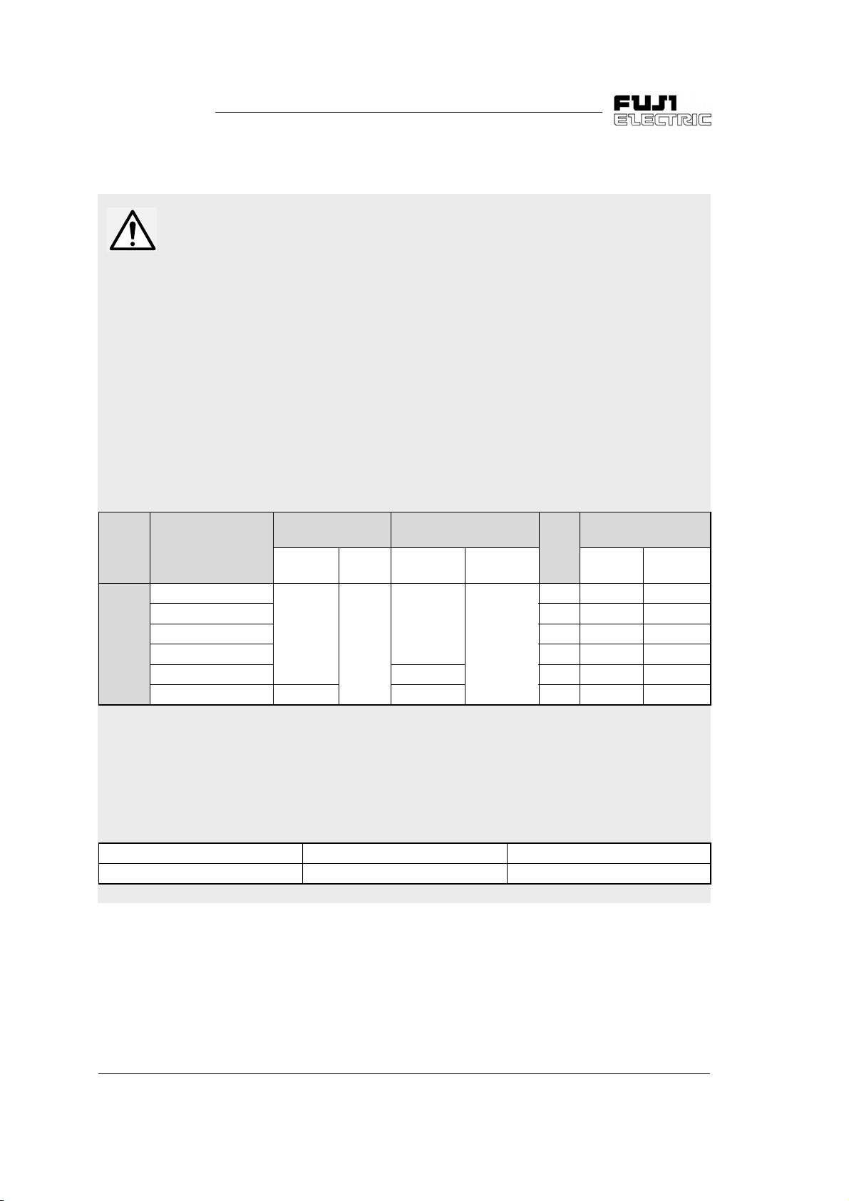
Voltage Inverter type
FVR0. 1C11S-7EN
Single-
phase
200V
input
FVR0. 2C11S-7EN 6 A4J6 JKS6
FVR0. 4C11S-7EN 10 A4J10 JKS10
FVR0. 75C11S-7EN 15 A4J15 JKS15
FVR1. 5C11S-7EN 12 (3.3) 30 A4J30 JKS30
FVR2. 2C11S-7EN 1.8 10 (5.3) 40 A4J40 JKS40
5. Perform wirin
verter, referrin
to the input, output and control terminals of the in-
to the table below. Use UL certified round crimp
terminal to the input and output terminals with insulation cover or
covered with reduced tube to obtain the insulation distance. Use a
crimpin
fabricatin
6. Install a fuse in the power suppl
tool recommended by the terminal manufacturer when
crimp terminals.
to the inverter, referring to the ta-
ble below.
Tightening torque
[Nm]
L1/L, L2/N
U, V, W
1.2
1) Use copper wires of allowable maximum temperature 60 or75 °C.
2) Use UL certified "quick breakin
Control
section
Applicable wire diameter
[AWG] (mm
L1/L, L2/N
U, V, W
14 (2.1)
0.4
2)1
Control
section
20 (0.5)
fuse".
Fuse
[A]
Recommended fuse
2
Gould
Compan
6 A4J6 JKS6
Bussmann
Compan
7. Connect the power supply satisfying the characteristics shown in
the table below as an input power suppl
circuit ratin
Inverter type Input max. voltage Input current
FVR0. 1-2. 2C11S-7EN AC240V 5,000 A or less
2 Safety Instructions
)
of the inverter. (Short
Page 5

FVR-C11S-EN
Ü
g
g
y
y
g
y
y
g
g
y
y
y
y
y sy
y
g
g
g
g
g
y
y
g
g
y
g
g
y
g
y
Compliance with low voltage directive in
EU [Applicable to products with T
V
mark]
CAUTION
1. Safe separation for control interface of this
inverter is provided when this inverter is installed in overvolta
(Protective Extra Low Volta
SELV (Safet
from external controller is connected to the
interface directl
2. Basic insulation for control interface of this
inverter is provided when this inverter is installed in overvolta
lation transformer has to be installed
between power suppl
verter when SELV circuit from external
controller is connected to this inverter directl
. Otherwise supplementary insulation
between control interface of this inverter
and environment must be provided.
3. The
round terminal G should always be
connected to the
RCD as the sole method of electric shock
protection. Dimensions of external PE conductor should be same as dimensions of
input phase conductor and capable for
possible fault.
Extra Low Voltage) circuit
e category II. PELV
e) circuit or
.
e category III. An insu-
mains and this in-
round. Don’t use onl
6. The inverter has to be installed in environment of pollution de
ment is pollution de
inverter has to be installed in a cabinet of
IP54 or hi
7. Use a prescribed wire accordin
EN60204 Appendix C.
8. Install the inverter, AC or DC reactor, output filter in an enclosure that meets the
followin
man bod
equipment.
1) When a person can touch easil
connectin
the inverter, AC or DC reactor, output filter in an enclosure with minimum de-
2) When a person can not touch easil
each connectin
install the inverter, AC or DC reactor,
output filter in an enclosure with a minimum de
9. It is necessar
propriate method usin
RFI filter to conform to the EMC directive.
It is customer’s responsibilit
whether the equipment, the inverter is installed in, conforms to EMC directive.
her.
requirement, to prevent a hu-
from touching directly to these
terminal or live parts, install
ree of protection of IP4X.
ree of protection of IP2X.
ree 2. If the environ-
ree 3 or 4, the
to the
on each
on
terminal or live parts,
to install the inverter in ap-
an appropriate
to check
4. Use MCCB or MC that conforms to EN or
IEC standard.
5. Where RCD (Residual-current-operated
protective device) is used for protection in
case of direct or indirect contact, onl
of t
pe B is allowed on the supply side of
this EE (Electric equipment). Otherwise another protective measure shall be applied
such as separation of the EE from the environment b
tion or isolation of EE and suppl
b
the transformer.
Safety Instructions 3
double or reinforced insula-
RCD
stem
Page 6

FVR-C11S-EN
y
g
)
)
)
)
g
)
)
)
)
)
)
)
)
)
)
)
g
g
g
y
y
y
g
g
g
y
Compliance with low voltage directive in EU [Continued]
Power
suppl
voltage
Single
phase
200V
CAUTION
Use of wires specified in Appendix C of EN 60204 is recommended.
Molded case circuit
breaker (MCCB) or
Nominal
applied
motor
[kW]
Inverter type
earth leaka
circuit breaker
(ELCB)
Rated current [A]
With
DCR
0.1 FVR0. 1C11S-7EN
0.2 FVR0. 2C11S-7EN
6
0.4 FVR0. 4C11S-7EN 10
0.75 FVR0. 75C11S-7EN 10 16
1.5 FVR1. 5C11S-7EN 16 20
2.2 FVR2. 2C11S-7EN 20 32
1) The applicable frame and series of the molded case circuit breaker (MCCB) and
earth leaka
transformer of the equipment. For details of selection, refer to the concernin
technical documents.
2) The recommended wire size for the main circuit is the case for the low volta
directive at ambient temperature 40 °C.
3) The power suppl
equivalent of 0.1% of the inverter capacit
accompanied b
4) Crimp terminals up to 7.4 mm in width (includin
5) Crimp terminals up to 9.5 mm in width (includin
6) Use the
suppl
e circuit breaker (ELCB) vary according to the capacity of the
the voltage imbalance.
rounding cable of a size equal to or larger than that of the input power
cable.
Recommended wire size [mm2]
e
1
Without
reactor
Input circuit
single phase
200V [L1/L, L2/N]
With
3
DCR
2
Without
reactor
[U, V, W]
3
Output
circuit
2
DCR
circuit
2
[P1]
[P(+)]
6
4
2.5
4
2.5
4
4.0
5
4.0
impedance without a reactor is considered to be the
5
6.0
, with 10% current imbalance
tolerance) can be used.
tolerance) can be used.
2.5
2.5
4
5
2.5
4.0
4
5
Control
wirin
0.5
e
4 Safety Instructions
Page 7

FVR-C11S-EN
g
y
y
y
y
y
y
g
g
g
g
jury
jury
g
g
jury
Instructions on use
CAUTION
WARNING
1. This inverter is designed to drive a threephase induction motor and is not usable for
a sin
le-phase motor or any other pur-
poses.
There is a risk of fire.
2. This inverter ma
elevator, life-support s
pose directl
mans.
Safet
precautions should be established
and practiced in terms of the entire s
rather than the independent device.
Otherwise, an accident could occur.
not be used as is for an
stem, or other pur-
affecting the safety of hu-
stem,
Instructions on transport/installation
WARNING
1. Attach the device to an incombustible material such as metal.
Otherwise fire could occur.
1. Do not carry the device by holding just the
surface cover.
Inverter ma
2. Do not allow forei
per dust, small chips of wood or metal, and
dust to enter the inverter or adhere to the
heat sink.
Otherwise, a disaster such as burnin
could occur.
3. Do not install or operate dama
or an inverter with a missin
Otherwise in
4. Do not step on the product.
Otherwise in
5. When stackin
the number of tiers indicated on the pack-
carton.
in
Otherwise in
be dropped causing injury.
n matter such as lint, pa-
ed inverter
part.
could occur.
could occur.
up in tiers, do not exceed
could occur.
2. Do not place the device near inflammables.
Otherwise fire could occur.
Safety Instructions 5
Page 8

FVR-C11S-EN
g
g
g
g
g
y
jury
g
y
g
g
y
y
jury
y
g
g
g
Instructions on wirin
CAUTION
WARNING
1. When the inverter is connected to power,
connect it via a line-protection molded case
circuit breaker or an earth-leaka
breaker (Residual current operated protective device).
Otherwise fire could occur.
2. Be sure to connect the
Otherwise electric shock or fire could
occur.
3. Ensure that a licensed specialist
performs the wirin
4. Check before startin
power is off (OPEN).
Otherwise electric shock could occur.
5. Do not wire up the inverter until it has been
installed securel
Otherwise electric shock or in
occur.
6. The inverter has to be
ance with the national and local safet
specification.
Otherwise electric shock could occur.
.
round wire.
work.
the wiring that the
rounded in accord-
e circuit
could
1. Check that the number of phases and the
rated volta
the number of phases and volta
AC power suppl
Otherwise fire could occur.
2. Do not connect the AC power suppl
output terminals (U, V, W).
Otherwise in
3. Check the output terminals (U,V,W) for the
phase order and connect them to the motor
correctl
Otherwise fire could occur.
4. Do not connect a brakin
the DC terminals [P(+), N(-)].
Otherwise fire could occur.
5. Noise is
tor, and wirin
does not cause malfunctions in peripheral
sensors and equipment.
Otherwise accidents could occur.
e of this product correspond to
e of the
.
to the
could occur.
.
resistor directly to
enerated from the inverter, mo-
. Take care that this noise
6 Safety Instructions
Page 9

FVR-C11S-EN
g
g
y
g
g
y
g
g
y
g
y
g
y
g
g
y
g
y
y
g
g
g
y
y
g
y
ging
g
j
g
j
Instructions on operation
WARNING
1. Be sure to put on the surface cover before
the power ON (CLOSE).
turnin
Never remove the cover while the power is
applied to the inverter.
Otherwise electric shock could occur.
2. Never operate switches with wet fin
ers.
Otherwise electric shock could occur.
3. The interior of the inverter ma
char
ed after turning off the power.
remain
Therefore, never attempt to remove the
surface cover except for wirin
service and
periodic maintenance.
Otherwise electric shock could occur.
WARNING
I
5. Never touch the inverter terminals when
ized even if it has stopped.
ener
Otherwise electric shock could occur.
6. Never touch the ke
s on the keypad panel
with a pointed object such as a needle.
Otherwise electric shock could occur.
CAUTION
1. Never touch the heat sink because the
become very hot.
Otherwise burns could occur.
2. The inverter can set hi
. Carefully check the limit of the mo-
easil
tor and machine before chan
tin
.
Otherwise in
uries could occur.
3. Do not use the inverter brake function for
mechanical holdin
Otherwise in
uries could occur.
h-speed operation
the set-
.
1. When the retry function is selected, the inverter ma
pin
(Desi
safet
automatically restart after trip-
, depending on the cause of the trip.
n the machine to secure personal
in the event of restart.)
Otherwise accident could occur.
2. Operatin
conditions may occasionally be
different from the preset acceleration/deceleration time or speed because of activation of the stall prevention function.
In such a case, personal safet
cured throu
h adequate machine design.
must be se-
Otherwise accident could occur.
3. The stop ke
tion settin
Therefore install an emer
dependentl
ternal si
ke
on the keypad panel will be disabled.
is effective only when a func-
has been established.
ency switch in-
. When operation via the ex-
nal terminal is selected, the STOP
There is a risk of accidents.
4. Operation starts suddenl
done with an runnin
that no runnin
signal is input before alarm
if alarm reset is
signal input. Check
reset.
Otherwise accidents could occur.
Safety Instructions 7
Page 10

FVR-C11S-EN
g
g
g
y
g
g
jury
y
jury
g
g
y
y
g
g
Instruction on maintenance/inspection,
and replacement
WARNING
1. Do not commence inspection work until at
least five minutes after the power has been
turned off (OPEN).
(In addition, make sure that the char
lamp has
volta
does not exceed 25V DC.)
Otherwise electric shock could occur.
2. Onl
maintenance and inspection or replacement operations.
(Take off all metal objects (watch, rin
etc.) before startin
(Use well-insulated tools.)
Otherwise electric shock or in
occur.
3. Never modif
Otherwise electric shock or in
occur.
one off and check that the DC
e between terminals P(+) and N(-)
qualified personnel should perform
.)
could
the product.
could
Instruction on disposal
CAUTION
Since this product contains lead solder,
it must be treated as industrial waste
when it is disposed of. Entrust it to a
waste processin
posin
e
General instructions
The figures in this operation manual ma
show the inverter with covers and safet
,
screens removed to explain the structure in
details. Therefore, be sure to replace the covers and screens to their ori
operate the inverter accordin
tion manual.
company when dis-
it.
inal positions and
to the instruc-
8 Safety Instructions
Page 11

FVR-C11S-EN
g
y
y
g
g
g
y
y
g
y
y
y
g
g
y
1Before Using This Product
1-1 Receivin
Inspections
Unpack and check the product as explained below.
If
ou have any questions or problems with this product, please contact
FUJI ELECTRIC Co., Ltd., or
1) Check the ratin
the ordered one.
Figure 1-1-1 Ratings nameplate
TYPE: Inverter Type
0.75 C11S - 7 EN
FVR
Series name
s name plate to confirm that the delivered product is
our local FUJI inverter distributor.
Series Extension (EN series)
Power volta
씯
7 Sin
Nominal applied motor: 0.75 0.75kW
Product t
e series:
le-phase 200V input series
씯
pe
1
SOURCE: Number of input phases, rated input voltage, rated in-
put frequenc
OUTPUT: Number of output phases, rated output capacity, rat-
ed output volta
put current, overload capacit
SER. No.: Product number
1 1725R0001
9
2) Check for dama
on the covers or the main unit upon deliver
ed parts, missing parts, and dents or other damage
, rated input current
e, output frequency range, rated out-
Production lot serial number
Production month:
1 to 9: Januar
X: October, Y: November, Z: December
Production
Last di
it of year (9: 1999)
to September,
ear:
.
1 Before Using This Product 1-1
Page 12
FVR-C11S-EN
g
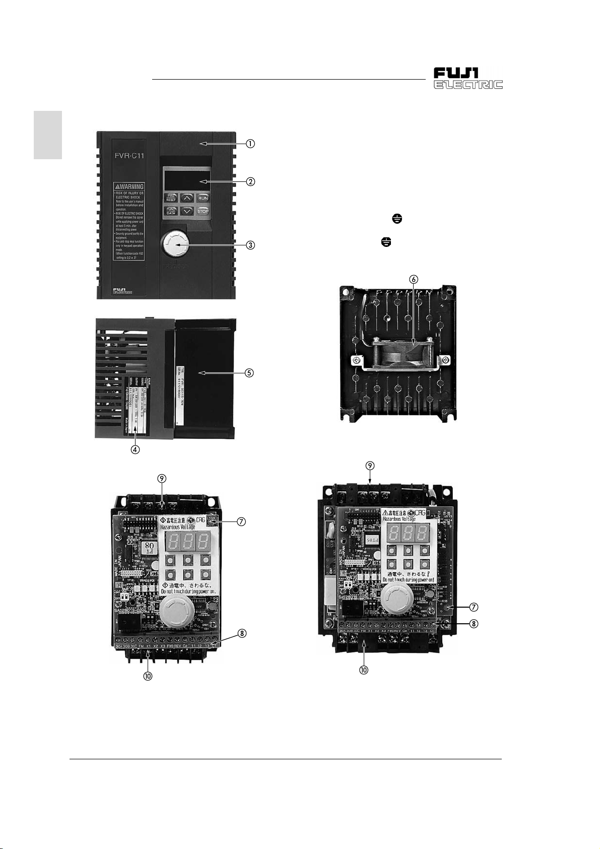
1-2 Appearance
1
Surface cover
Keypad panel
Frequency setting POT (VR) (built-in POT)
Ratings nameplate
Heat sink
Cooling fan (1.5 kW or more)
Charge lamp CRG
Control terminal block
Main circuit terminal block
le-phase 200V[ G,L1/L,L2/N,P1,P(+)]
Sin
Main circuit terminal block
[P(+),N(-),U,V,W, G]
1-2 1 Before Using This Product
Page 13

FVR-C11S-EN
y
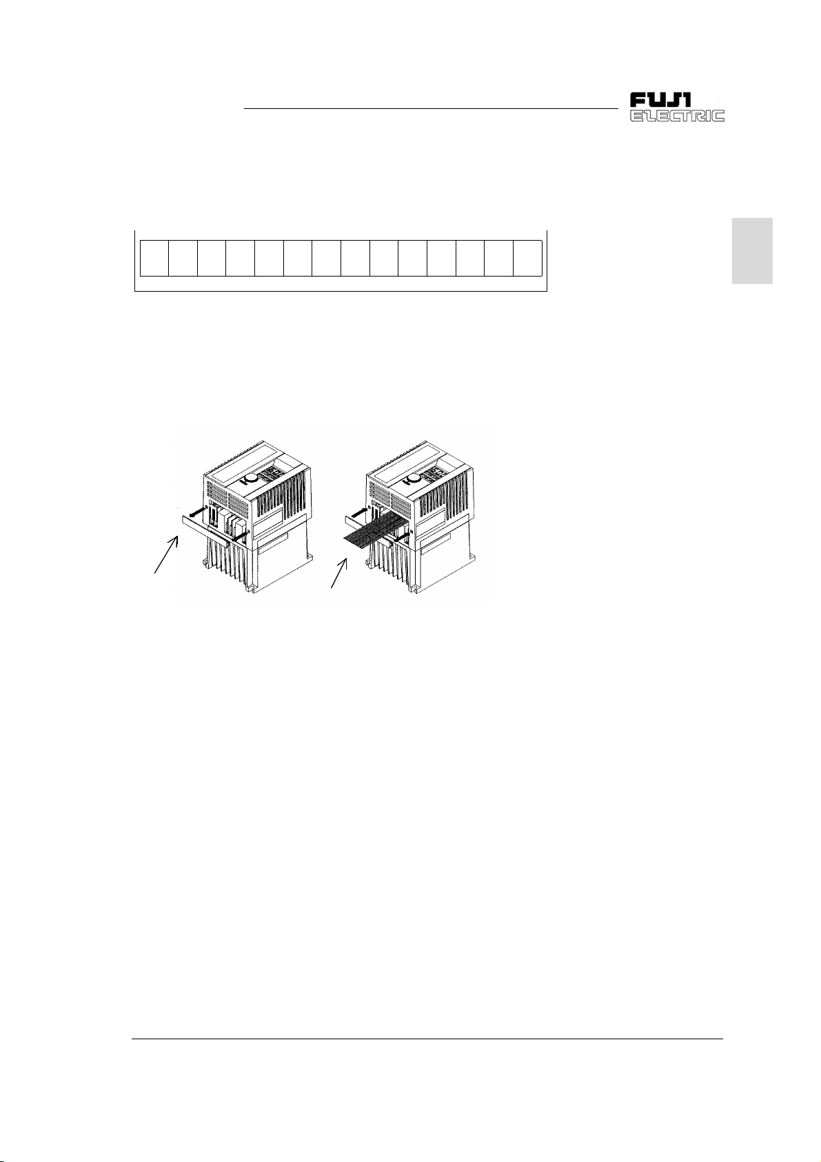
1-3 Handling the Product
Remove the surface cover as explained below.
1) For FVR0.1 to 0.75C11S-7EN
Grasp the upper and lower parts of the cover
with both hands and pull it to the front of the
inverter.
2) For FVR1.5 to 2.2C11S-7EN
Expand the lower part of the cover horizontal-
, lift the cover to the front, and then remove
l
it.
1
1 Before Using This Product 1-3
Page 14

FVR-C11S-EN
g
y
y
g
y
y
g
g
g
y
y
y
1-4 Carryin
1
1-5 Storage and
transportation
Item Specifications
Storage temperature Transportation
temperature
Relative humidit
Atmosphere The product must not be exposed to dust, direct sunlight, corrosive gas, in-
Air pressure 86 to 106kPa (During storage)
Always hold the main unit while carrying this product.
If it is carried b
be damaged or dropped.
ma
Force must not be applied to the inverter cover durin
it is made of plastic.
Store and transportation this product under the conditions listed in
Table 1-5-1.
-25 to +65 °C Condensation or formation of ice must not be
5 to 95%
flammable
salt in the atmosphere.
70 to 106kPa (Durin
1)
as, oil mist, vapor, water drops, or vibration. There must be no
the cover or parts and not the main unit, the product
carrying because
caused b
transportation)
sudden temperature changes.
Table 1-5-1 Storage and transportation environment
1) A large change in temperature within this humidity range may cause condensation
or formation of ice. Do not store this product at a place where such chan
[Storage precautions]
1. Do not locate this product directly on a floor; place it on a rack or
shelf.
2. To store the product in a severe atmosphere, pack it in vin
3. If the product must be stored at a place where it ma
humidity, insert a drying agent such as silica gel and pack it in vinyl
sheet.
es occur.
l sheet.
be affected b
1-4 1 Before Using This Product
Page 15

FVR-C11S-EN
g
y
g
y
2 Installation and Connection
2-1 Operatin
Environment
Item Specifications
Place Indoor
Ambient temperature -10 to +50 °C
Ambient relative humidit
Atmosphere The product must not be exposed to dust, direct sunlight, corrosive
Altitude 1000 m or less (Air pressure : 86kPa to 106kPa)
Vibration 3mm: 2 ~ 9 Hz or less
Table 2-1-1 Operating environment
Install this product at a place satisfying the conditions listed in
Table 2-1-1.
5 to 95%RH (No condensation allowed)
as, inflammable gas, oil mist, vapor, or water drops.
There must be no salt in the atmosphere. Condensation must not
be caused b
9.8 m/s
2
2 m/s
2
1 m/s
sudden changes in temperature.
2
: 9 ~ 20 Hz or less
: 20 ~ 55 Hz or less
: 55 ~ 200 Hz or less
2
2 Installation and Connection 2-1
Page 16
FVR-C11S-EN
g
g
g
g
y
g
g
g
g
y
g
y
y
y
g
y
g
g
y
y
y
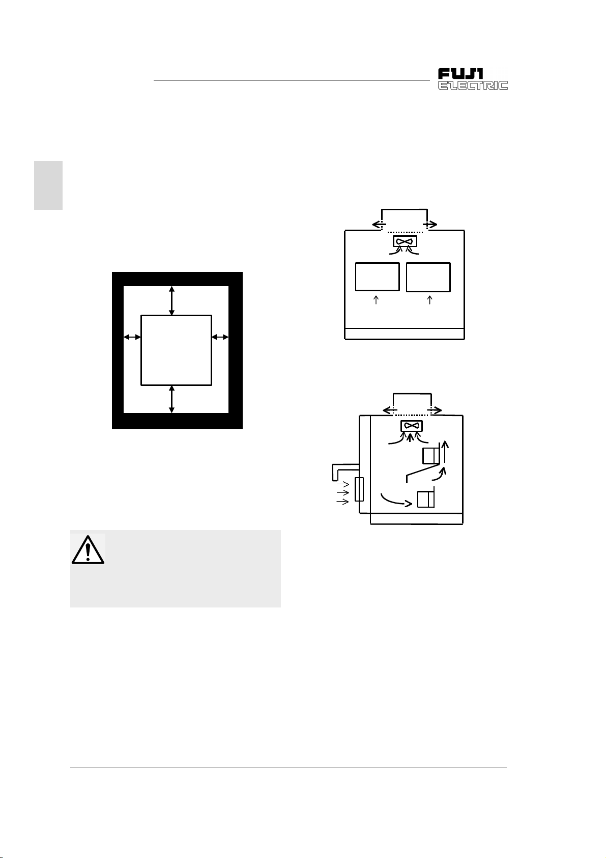
2-2 Installation Method
1. Tightly fasten the product in the upright posi structure using four bolts
fan, so do not install this prod-
10cm
2
tion on a stron
(M4) with the characters FVR-C11 facin
front. Be sure not to turn the product upside
down, and install it on a horizontal surface.
2. Heat is
in
necessar
enerated while the inverter is operat-
, so the gaps shown in Figure 2-2-1 are
for the passage of cooling air. The
enerated heat is radiated upward by the
built-in coolin
uct below a device that is sensitive to heat.
10cm
1cm FVR-C11 1cm
the
5. If two or more inverters need to be installed in
the same device or control panel, the
be arran
ed horizontally to minimize the influ-
should
ence of heat between them. If two or more inverters must be installed verticall
, place a
plate between them to prevent the upper inverter from bein
affected by heat from the
lower inverter.
Inverter
Air suppl
a) Horizontal arrangement
Inverter
Air suppl
Figure 2-2-1 Installation direction and surrounding space
3. The temperature of the heat sink increases to
about 90 °C while the inverter is operatin
Therefore, the surface behind where the
product is located must be able to withstand
this temperature increase.
WARNING
Install this product on a nonflammable
material such as metal.
Otherwise fire could occur.
4. When installin
el, carefull
vent the ambient temperature of the inverter
from exceedin
install it in a hermeticall
which heat is not radiated full
this product in a control pan-
consider the ventilation to pre-
the specified value. Do not
sealed box from
.
Inverter
Plate
.
Air
suppl
b) Vertical arran
Figure 2-2-2 How to install two or more inverters
Inverter
ement
2-2 2 Installation and Connection
Page 17

FVR-C11S-EN
y
g
y
g
ysg
g
g
y
g
g
g
y
g
y
g
g
g
y
g
g
g
CAUTION
Do not allow foreign matter such as
lint, paper dust, small chips of wood or
metal, and dust to enter the inverter or
adhere to the heat sink.
Otherwise, a disaster such as burnin
could occur.
2-3 Connection
Remove the surface cover to connect the terminal blocks. Correctl
the followin
procedures.
2-3-1 Basic connection
1. Always connect the power to the main power
suppl
input terminal of the inverter. If it is
connected to another terminal, the inverter
will be dama
2. Alwa
disasters such as fire and electric shock and
to minimize noise.
round the ground terminal to prevent
connect them according to
ed (see Figure 2-3-1).
WARNING
1. Always connect the ground wire.
Otherwise electric shock and fire could
occur.
2. Ensure that a licensed specialist performs
the wirin
3. Check before startin
power is off.
Otherwise electric shock could occur.
work.
the wiring that the
2
3. Use a reliable crimp terminal for connection
between a terminal and wire.
4. After terminatin
check the followin
a. Whether the connection is correct
b. Whether all necessar
been made
c. Whether there is a short-circuit or
fault between terminals and wires
5. Connection modification after power-on
The smoothin
part of the main circuit cannot be dischar
quickl
multimeter to check that the volta
rect current (DC) is reduced to the safet
range (25V DC or less) after the charge lamp
a
cause the residual volta
ma
after the power is turned off. Use a
oes off to avoid danger. Check that the volt-
e is zero before short-circuiting a circuit be-
cause sparks.
the connection (wiring),
items:
connections have
round
capacitor in the direct current
ed
e of the di-
e (electric charge)
2 Installation and Connection 2-3
Page 18
FVR-C11S-EN
g
g
y
g
y
g
g
g
g
y
g
g
y
y
y
y
g
g
y
g
y
g
g
g
y
g
y
g
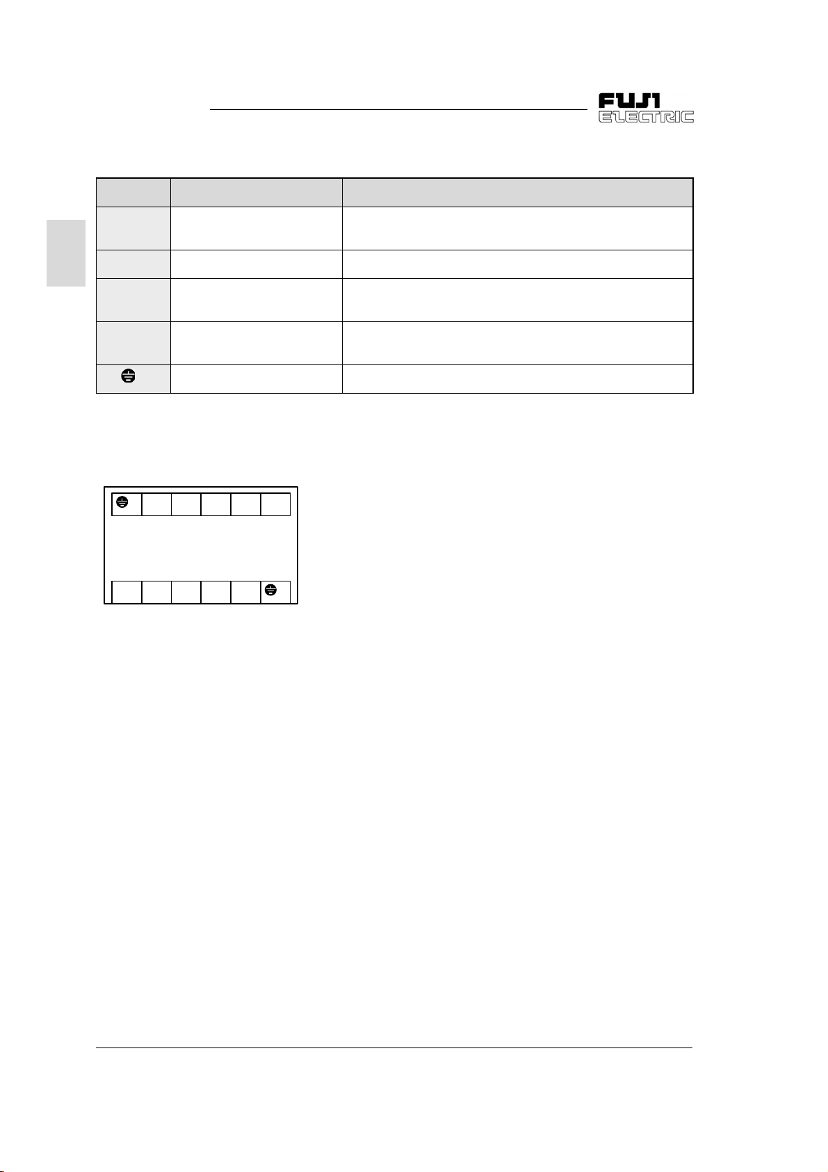
2-3-2 Connecting the main circuit and ground terminals
Symbol Name Explanation
L1/L,L2/N Main power supply input Connects single-phase power
le-phase 200V input).
2
U, V, W Inverter output Connects 3-phase motor.
(Sin
P1, P(+) For connection of DC
reactor
P(+), N(-) For DC intermediate
circuit
G For inverter groundin
Table 2-3-1 Functions of main circuit and ground terminals
1) Main power suppl
Sin
le-phase 200V [L1/L,L2/N]
For single-phase 200V input
FVR-C11S-7EN
Figure 2-3-1 Arrangement of main circuit and ground
terminals
input terminal
P(+)P1L2/NG L1/L
GWVUN(-)P(+)
Connects input power- factor correcting DC reactor
(optional).
Connected to DC link circuit terminal
(for DC bus connection).
Ground terminal for inverter chassis (case).
1. Connect the main power supply input ter-
minals to the power suppl
via a molded
case circuit breaker for circuit protection or
earth leaka
leaka
e circuit breaker. An earth-
e circuit breaker which can also detect DC current is recommended. Phasesequence matchin
2. It is recommended that a ma
tor is connected to prevent an
accident from becomin
nectin
the inverter from the power suppl
is unnecessary.
netic contac-
failure or
serious by discon-
when the inverter protective function operates.
3. Do not turn on or off the main power suppl
to start or stop the inverter; instead, use the
control circuit terminal FWD/REV or the
RUN/STOP ke
on the keypad panel. If it
is unavoidable to turn the main power sup-
on or off to start or stop the inverter, it
pl
must not exceed once per hour.
2) Inverter output terminal [U, V, W]
1. Connect these terminals to the 3-phase
motor with the correct phase-sequence. If
a motor rotation direction does not correspond to the correct rotation direction, exchan
e any two of the U, V, and W phases.
2. Do not connect a phase-advance capacitor or sur
3. A ver
e absorber to the inverter output.
long wiring length between the inverter and the motor causes a hi
quenc
current to flow due to floatin
capacity between cables, making the inverter trip, increasin
and deterioratin
rent displa
wirin
. To prevent such trouble, the
length to the motor should not ex-
the leakage current
the accuracy in the cur-
ceed 50 meters.
When the inverter is operated in the low
noise mode (carrier frequenc
kHz) and the wirin
length is long, add an
: 8 to 15
optional output circuit filter (OFL filter).
h fre-
2-4 2 Installation and Connection
Page 19
FVR-C11S-EN
g
y
g
g
g
ysg
y
g
y
y
g
g
g
g
y
y
y
g
g
g
g
g
g
y
y
jury
g
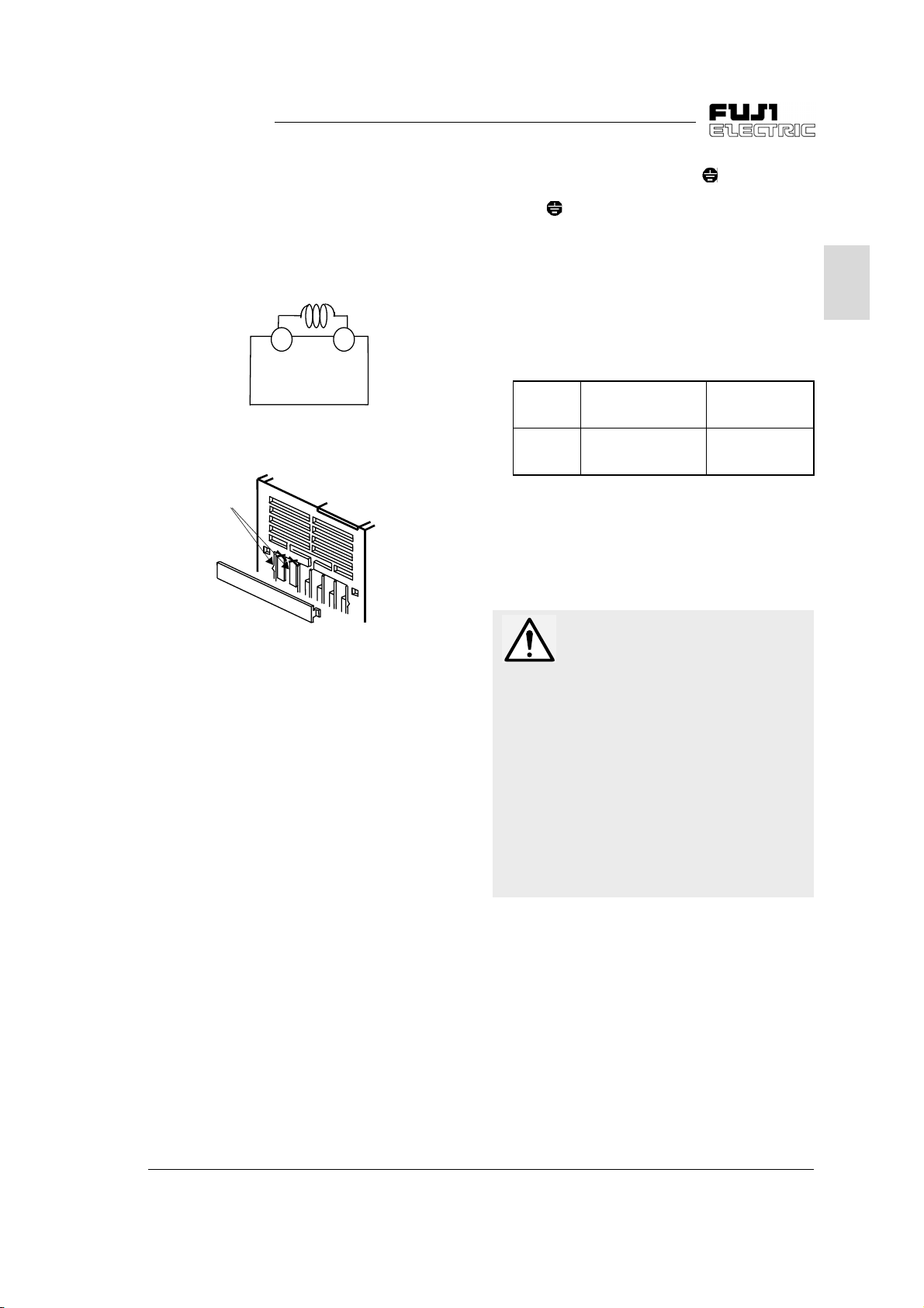
3) DC reactor connecting terminal [P1, P(+)]
1. Use this terminal to connect a input powerfactor correctin
DC reactor (optional).
Remove the jumper connected in the factor
before connecting the DC reactor (see
ure 2-3-2).
Fi
P1
FVR-C11S-7EN
a) Connection diagram
Top of inverter
Barrier
P(+)
4) Inverter
Alwa
nal [ G] for safet
Groundin
rounding terminal [ G]
round the inverter grounding termi-
and noise reduction.
of the metal frames of electric
equipment has to be done in accordance with
the national and local safet
specifications in
force.
1. In Japan, the 200V s
nected to a
class D
round electrode provided with
rounding, according to the electri-
stem must be con-
cal equipment technical standard.
Voltage
stem
s
200V
Table 2-3-2 Grounding of device according to
T
pe of ground-
work
in
Class D
roundin
electrical equipment technical standard
Groundin
resistance
100
Ω
maximum
2. Connect a thick and short wire to the
rounding terminal of the inverter for connection with a
exclusivel
round electrode prepared
for the inverter system.
2
b) Cuttin
Figure 2-3-2 Connection of DC reactor
of barrier
2. Use diagonal cutting pliers to cut the surface cover barriers from P1, P(+) terminals
before connection.
3. If no DC reactor is used, do not remove the
jumper.
CAUTION
1. Check that the number of phases and the
rated volta
to the number of phases and volta
AC power suppl
Otherwise fire could occur.
2. Do not connect the AC power suppl
output terminals (U, V, W).
Otherwise in
3. Do not connect a brakin
the DC terminals P(+), N(-).
Otherwise fire could occur.
e of this product correspond
e of the
.
to the
could occur.
resistor directly to
2 Installation and Connection 2-5
Page 20
FVR-C11S-EN
g
g
g
g
y
y
g
2-3-3 Connecting the control terminals
Table 2-3-4 lists the functions of the control circuit terminals.
The method of connectin
nal depends on how its function is set.
Connect the control circuit terminals accordin
2
to the set functions.
1) Di
ital input terminal
Fi
ure 2-3-3 shows the circuit configuration.
Use a reliable contact without poor contact for
input.
Example: FUJI control rela
FWD or others
+24 to
+27VDC
SW7
P24/CM
FVR-C11S-7EN
a control circuit termi-
HH54PW
4.7k
CM
P24
0 V
F1
+24 to
+27VDC
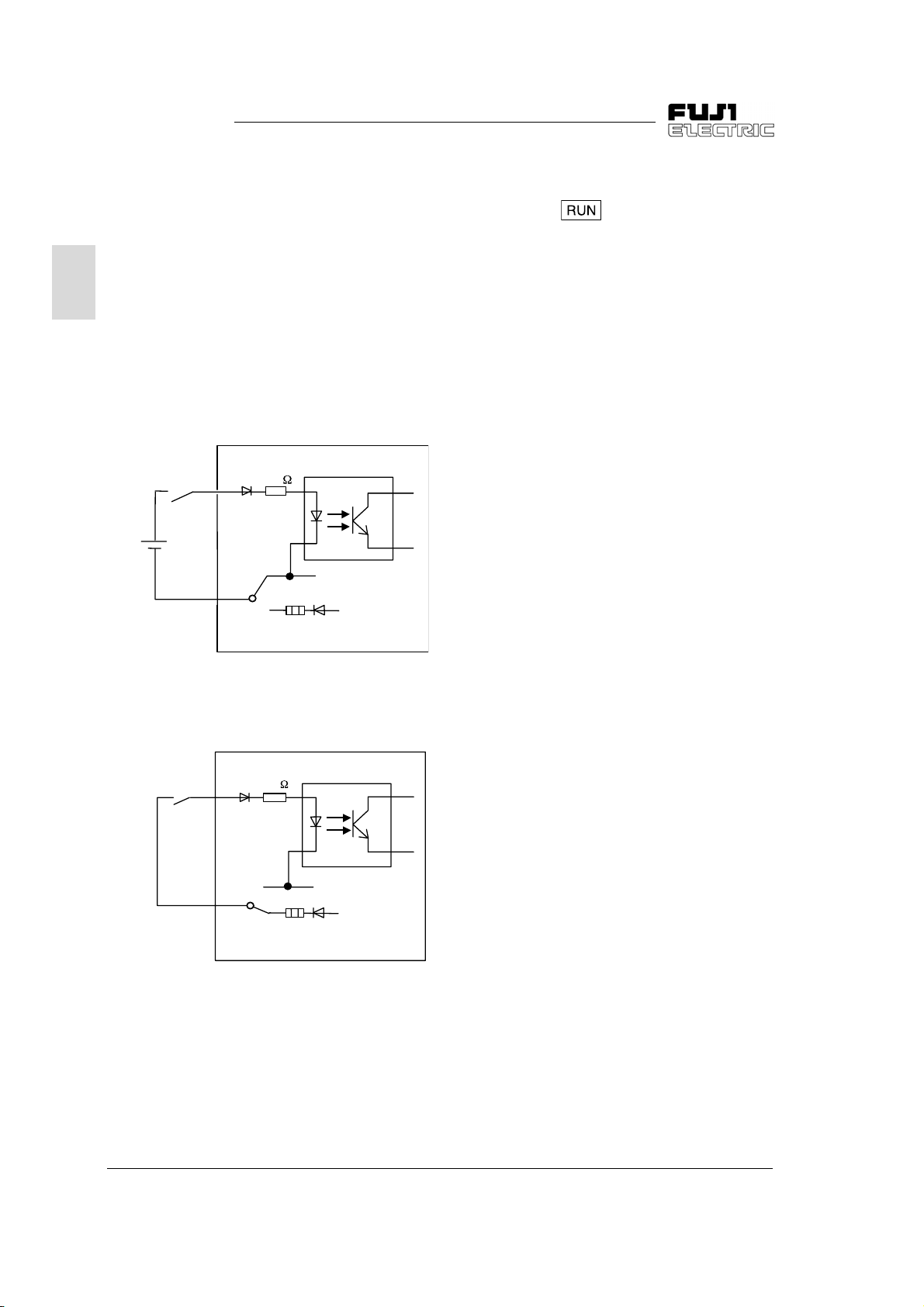
2) Run/stop command terminal [FWD, REV]
These terminals are left open in the factor
Pressin
the key on the keypad panel
starts forward operation. When function F02
is set at 0 or 1, the terminal functions are as
shown in Table 2-3-3.
.
a) When SW7 is set to CM (factory setting)
FWD or others
P24/CM
40mA max.
4.7k
CM
SW7
FVR-C11S-7EN
F1
P24
0 V
+24 to
+27VDC
b) When SW7 is set at P24
Figure 2-3-3 Digital input terminal
2-6 2 Installation and Connection
Page 21
FVR-C11S-EN
g
y
g
y
y
y
g
g
g
y
g
g
y
y
g
g
g
g
y
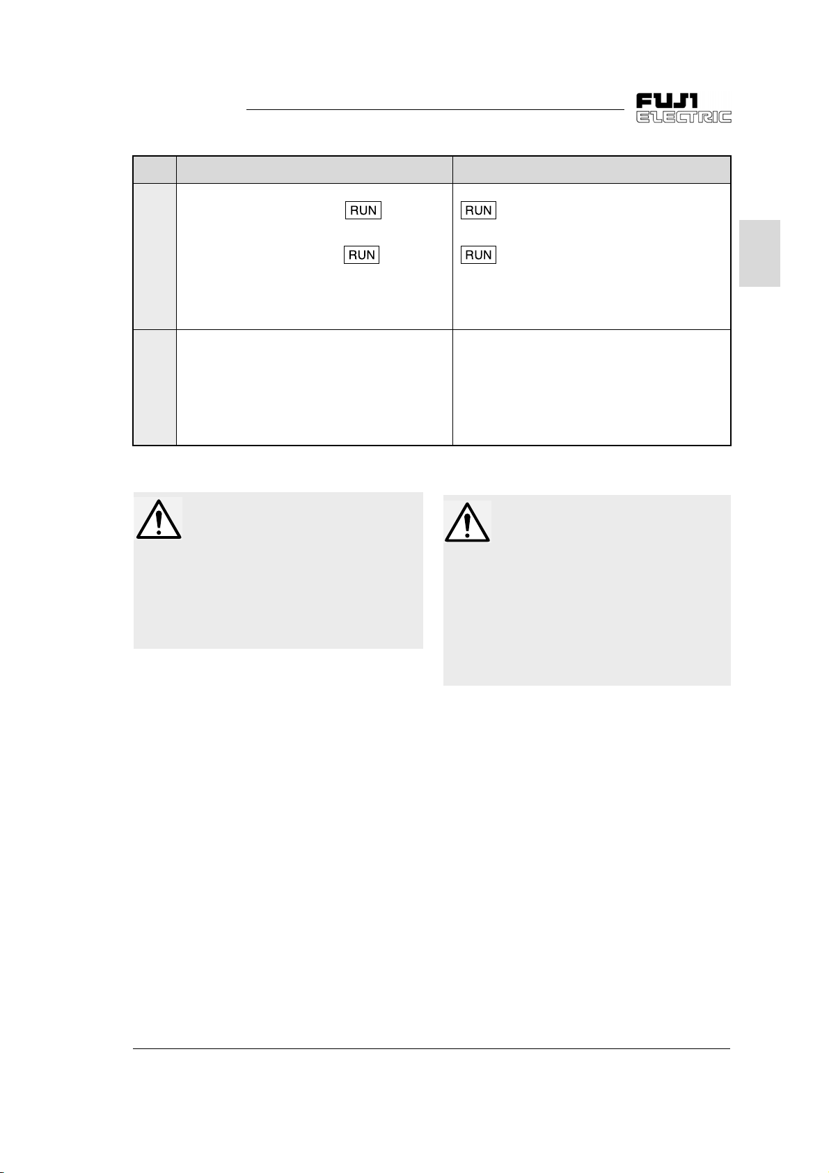
F02 When SW7 is set at CM When SW7 is set at P24
When +24 to +27 VDC is supplied to
FWD - P24/CM, pressin
ke
pad panel starts forward operation.
When +24 to +27 VDC is supplied to
0
REV - P24/CM, pressin
pad panel starts reverse operation.
ke
When +24 to +27 VDC is supplied to both
FWD - P24/CM and REV - P24/CM, the inverter
decelerates to stop.
When +24 to +27 VDC is supplied to
FWD - P24/CM, forward operation starts.
When +24 to +27 VDC is supplied to
1
REV - P24/CM, reverse operation starts.
When +24 to +27 VDC is supplied to both
FWD - P24/CM and REV - P24/CM, the inverter
decelerates to stop.
Table 2-3-3 Description of function F02
the key on the
the key on the
CAUTION
In case P24 is short-circuited with 0V
outer circuit when SW7 is set to P24
b
side, pol
off. To recover the power, open the
short circuit and turn the inverter off to
allow the temperature to lower.
3) Analog input terminal (13, 12, 11, C1)
Use these terminals to connect external input
voltage and analog current and fre-
analo
quenc
setting device (POT). For connectin
a contact to this circuit, use a twin contact for
fine current si
Do not use a contact for terminal 11.
switch (F1) turns the power
nal.
When FWD is short-circuited to P24/CM and the
on the keypad panel is pressed, for-
ke
ward operation starts.
When REV is short-circuited to P24/CM and the
on the keypad panel is pressed, re-
ke
verse operation starts.
When both FWD - P24/CM and REV - P24/CM
are short-circuited, the inverter decelerates to
stop.
Short-circuit FWD to P24/CM for forward operation, or REV to P24/CM for reverse operation.
Short-circuitin
P24/CM brin
stop.
both FWD - P24/CM and REV -
s the inverter to deceleration and
WARNING
The STOP key is valid only when the
function has been set. Prepare
another switch for emer
When operation usin
nal terminal is selected, the operation
cannot be stopped usin
ke
on the keypad panel.
Otherwise accidents could occur.
ency stop.
an external si-
the STOP
2
2 Installation and Connection 2-7
Page 22
FVR-C11S-EN
g
g
y
g
g
g
y
g
g
g
y
g
y
y
y
g
g
g
g
g
y
y
y
g
g
g
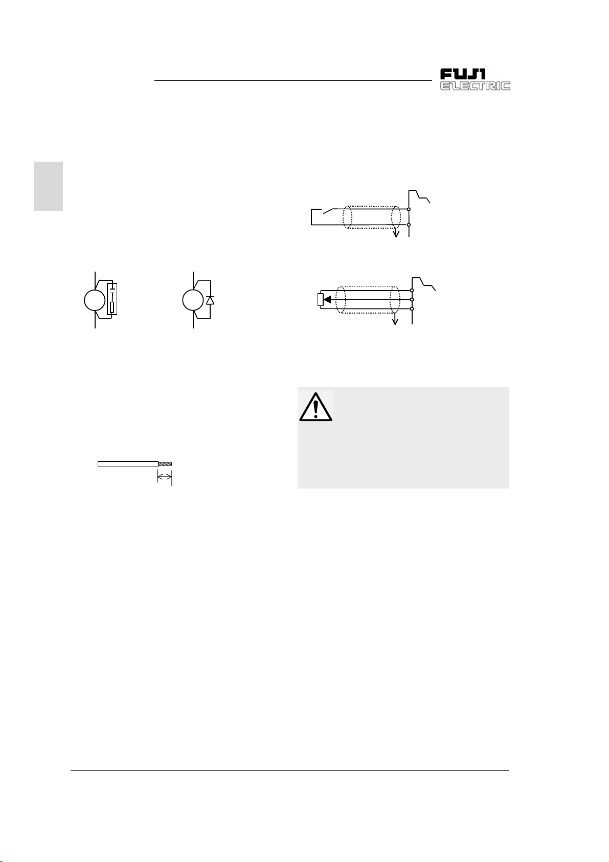
*Note the following when wiring:
1) Sur
e absorber connection
When the excitin
in the control circuit or inverter
e. Due to this surge voltage,
2
tactor or rela
peripheral circuit is opened or closed, a sur
e (noise) is generated with a sudden
volta
current chan
the inverter control circuit or peripheral equipment ma
a sur
(See Fi
AC rela
MC
SK: Surge absorber D: Diode
Figure 2-3-4 Surge absorber connection diagram
malfunction. If so, directly connect
e absorber to both ends of the coil.
ure 2-3-4).
SK
2) Control circuit wirin
1. Wires connected to control circuit terminals must be 0.5mm
twisted vin
shown in Fi
l wire. Remove the sheath as
ure 2-3-5 and then connect it.
coil of the magnetic con-
DC rela
+
Ry
D
-
2
shielded wire or
e
3) Shieldin
Connect one end of the shieldin
sheath connection
sheath of a
shielded or twisted-pair shielded wire to the
round terminal as shown in Figure 2-3-6. Do
not connect the other end.
Contact
Frequenc
setting POT
Figure 2-3-6 Connection of sheath of shielded wire
Shield
round terminal
To
Shield
To
round terminal
FWD
P24/CM
13
12
11
CAUTION
Noise is generated from the inverter,
motor, and wirin
noise does not cause malfunctions in
peripheral sensors and equipment.
Otherwise accidents could occur.
. Take care that this
6 ±1mm
Figure 2-3-5 End treatment
2. Keep the wiring of the main circuit, external rela
cuit as far awa
possible. If the
them at ri
sequence circuit and control cir-
from each other as
must be adjacent, cross
ht angles.
3. Use a twisted-pair shielded wire for lon
wiring distances.
2-8 2 Installation and Connection
Page 23
FVR-C11S-EN
g
g
g
g
g
g
g
g
g
g
4) Control terminal arrangement, screw size,
htening torque.
and ti
ure 2-3-7 shows the control terminal block
Fi
ement.
arran
REV
P24
/CM
30A 30B 30C FM X1 X2 X3
Figure 2-3-7 Control terminal block arrangement
FWD
5) Remove the plate at the bottom of the surface
cover before performin
and reinstall it after the wiring as shown in
in
ure 2-3-8.
Fi
inverter control wir-
Screw size: M2.5
htening torque: 0.4 Nm
Ti
11 12 13 C1
2
Plate
Control wirin
ure 2-3-8 How to pull out the control wirin
Fi
2 Installation and Connection 2-9
Page 24

FVR-C11S-EN
y
g
y
y
y
g
y
g
g
g
g
y
g
g
y
g
g
g
y
g
y
2
Classifi-
cation
Analo
input
Digital
input
Terminal
s
mbol
13
12
C1
Terminal name
Power suppl
variable resistor
Frequenc
voltage input
Frequenc
current input
11 Analo
FWD
Forward operation
/Stop command
Reverse
REV
operation
/Stop command
X1 Di
X2 Di
X3 Di
(SS1)
(SS2)
(BX)
ital input 1
ital input 2
ital input 3
Multistep
frequenc
selection
Coast to stop
command
(RST) Alarm reset
(THR)
External alarm
input
Write-enable com-
(WE-KP)
mand for ke
(data chan
lowed)
settin
settin
common
e al-
Detailed specifications
Used as power supply for frequenc
z
for
setting device
(POT: 1 to 5 k
(+10VDC 10mADC max.)
0 to +10VDC/0 to 100%,0 to +5VDC/0
z
to 100% (Input impedance : 22 k
4 to 20mADC/0 to 100%
z
(Input impedance : 250
Common terminal for analog input
z
nals
si
Forward operation with
z
FWD-P24/CM ON and
deceleration-stop with
FWD-P24/CM OFF
(Switch SW7 to P24)
Reverse operation with
z
REV-P24/CM ON and
deceleration-stop with
REV-P24/CM OFF
(Switch SW7 to P24)
The functions listed below can be set
z
the X1 to X3 terminal functions.
b
Up to four steps speed operation can
z
be selected with SS1 and SS2
ON/OFF si
Inverter output is cut immediately and
z
the motor coasts to a stop (no alarm
output) if BX
The inverter releases the status held
z
after stop with an alarm when RST
chan
The inverter stops with an alarm if
z
THR is set to OFF.
Data rewriting for each function with
z
pad
the ke
is OFF.
Rewriting with keypad panel is
z
allowed if WE-KP is ON.
).
Ω
Ω
)
Ω
nals.
oes on.
es from ON to OFF.
pad panel is rejected if WE-KP
Remarks
)
Deceleration-stop
with
FWD-P24/
CM and
REV-P24/
CM ON
Set with
functions
E01 to E03
2-10 2 Installation and Connection
Page 25

FVR-C11S-EN
y
g
g
g
g
g
g
g
y
g
y
g
y
y
y
g
g
g
g
g
Classifi-
cation
Digital
input
Output/
Input
Analo
output
Contact
output
Optional
Terminal
s
mbol
Terminal name
(Hz/PID) PID control cancel
(LE)
P24/CM
FM, 11 Analo
30A
30B
30C
DX+
DX-
Link operation
selection
Power Supply/
Di
ital Common
monitor
Alarm output for
fault
an
RS485 communication input/output
Detailed specifications
z
PID control cancel with Hz/PID ON
z
PID control with Hz/PID OFF
z
Operation based on command from
RS485 with LE ON
z
Inverter single operation with LE OFF
z
DC Power supply (SW7 set to P24)
(+24 to +27 VDC, 40mA max.)
z
Common terminal for digital input
si
nal (SW7 set to CM) (factory set-
)
tin
Data selected between the followin
items is output with DC voltage:
z
Output frequenc
z
PID feedback value
z
Output current
z
DC link circuit voltage
* Up to two analo
impedance : 10 k
voltmeters (input
Ω)
can be connected.
Note: Output waveform: An AC pulse
is output with consistent frequenc
and variable duty.
The avera
portional to output frequenc
e DC voltage is pro-
and
output current
(frequenc
: 121.6 Hz).
If the inverter is stopped with an alarm,
the non-volta
e contact signal (1SPDT)
is output
(Contact ratin
: 250V AC, 0.3 A, Power
factor = 0.3)
(48V DC, 0.5A for Low-volta
e Directive
or 42V DC, 0.5A for UL/cUL)
* Whether an alarm is
excitin
operation or non-exciting opera-
enerated with an
tion can be switched.
z
Terminal for RS485 communication
(when option board is installed)
z
DX+ : Non-inverted signal,
z
DX- : Inverted signal
Remarks
Switchin
of
P24/CM terminal with
switch SW7
Installed
on optional
board.
2
Table 2-3-4 Functions of control circuit terminals
2 Installation and Connection 2-11
Page 26
FVR-C11S-EN
g
g
y
g
y
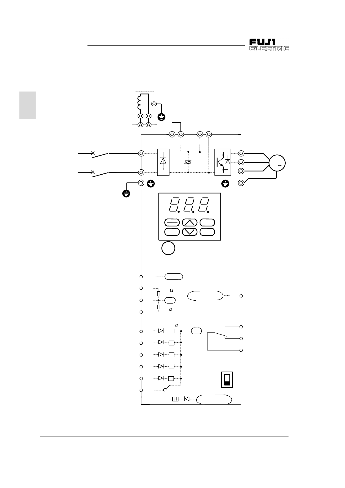
2-3-4 Connection examples
1) Keypad panel operation
2
le-phase
Sin
200V input
series
200 to 240V
50/60Hz
When power-factor
correctin
DC reactor is used
MCCB
P1
E
P(+)
L1/L
L2/N
G
Frequenc
P(+) P(+)
P1
PRG
RESET
FUNC
DATA
setting POT (VR)
2)
N(-)
U
V
W
M
3
G
RUN
STOP
13
12
11
C1
FWD
REV
X1
X2
X3
P24/
CM
Figure 2-3-9 Wiring diagram of keypad panel operation
SW7
+10VDC
22k
0V
250
4.7k
CM
P24
F1
Pulse output
0V
+24 to +27 VDC
SW7
P24
CM
FM
30A
30B
30C
Analo
monitor
Alarm output for
fault
an
2-12 2 Installation and Connection
Page 27

FVR-C11S-EN
y
y
g
y
y
g
g
g
g
1) The RUN and STOP keys on the keypad panel can be used to start and stop the operation
and the frequenc
used to set a frequenc
the power supply and motor with functions set
in the factor
.
factor
2) Remove the jumper between the P1 and P(+)
terminals before connectin
er-factor correctin
setting POT (VR) can be
only by connectin
. Forward rotation is set in the
the optional pow-
DC reactor.
2
3) Connect the sur
(such as coils of the ma
solenoid) near the inverter.
e absorber in parallel to coils
netic contactor and
2 Installation and Connection 2-13
Page 28
FVR-C11S-EN
y
g
g
y
g
y
g
g
g
y
g
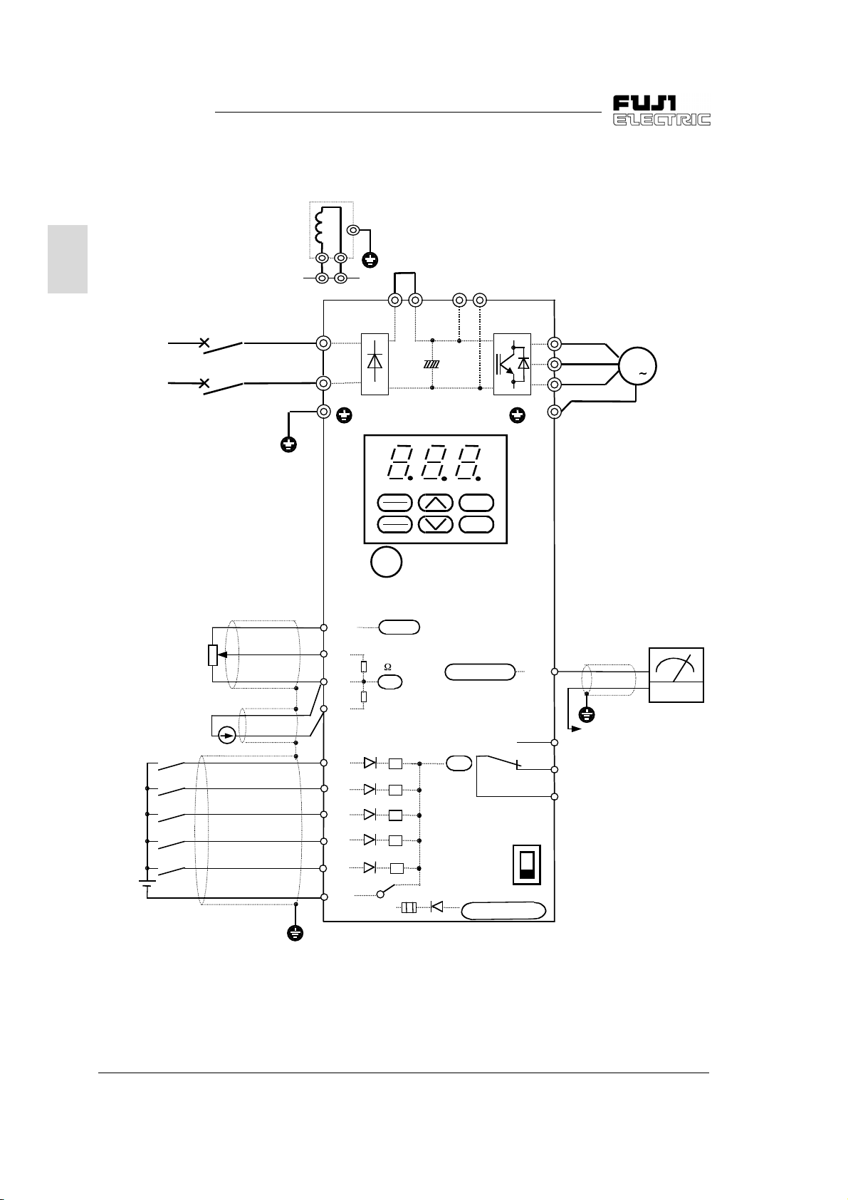
2) External operation
(When external power suppl
is used)
2
When power-factor
correctin
DC reactor is used
le-phase
Sin
200V input
series
200 to 240V
50/60Hz
Frequency settin
voltage input
(0 to +10VDC)
Frequenc
current input
(4 to +20mADC)
Forward
operation
command
Reverse
operation
command
settin
MCCB
P1
E
P(+)
L1/L
L2/N
Frequenc
13
12
C1
FWD
REV
X1
X2
P1 P(+) N(-)P(+)
PRG
RESET
FUNC
DATA
setting POT (VR)
10VDC
22k
0V
250Ω
4.7k
Ω
3)
RUN
STOP
Pulse output
0V
30A
30B
30C
SW7
P24
U
V
W
M
3
GG
Analo
Analo
monitor
To
To 11 terminal
Alarm output for
an
fault
meter
round terminal
24VDC
X3
P24/
CM
SW7
P24
CM
F1
+24 to +27 VDC
CM
Toground terminal
Figure 2-3-10 Wiring diagram of external operation (When external power supply is used)
2-14 2 Installation and Connection
Page 29

FVR-C11S-EN
y
g
g
g
g
g
g
1) Use this connection to start, stop the operation and set the frequenc
nals. 0 to 10V DC can be set while function
F01 is set to 1 and +4 to +20mA DC can be
set while function F01 is set to 2. Set function
F02 to 1.
2) Set SW7 at CM
3) Remove the jumper between the P1 and P(+)
terminals before connectin
er-factor correctin
DC reactor.
with external sig-
the optional pow-
2
4) Connect the sur
(such as coils of the ma
solenoid) near the inverter.
5) Use twisted or shielded wire as control si
wire. Connect the shield to the
nal.
e absorber in parallel to coils
netic contactor and
round termi-
nal
2 Installation and Connection 2-15
Page 30

FVR-C11S-EN
y
(+)
g
g
y
g
y
g
g
g
y
g
3) External operation
(When internal power suppl
is used)
2
When power-factor
correctin
DC reactor is used
le-phase
Sin
200V input
series
200 to 240V
50/60Hz
Frequency settin
voltage input
(0 to +10VDC)
Frequenc
current input
(4 to +20mADC)
Forward
operation
command
Reverse
operation
command
settin
P1
E
P
L1/L
L2/N
G
Frequenc
13
12
C1
FWD
REV
X1
X2
3)
P1 P(+) N(-)P(+)
PRG
RESET
FUNC
DATA
setting POT (VR)
10VDC
22k
0V
250
4.7k
RUN
STOP
Pulse output
0V
30A
30B
30C
SW7
P24
U
V
W
M
3
G
Analo
Analo
monitor
To
To 11 terminal
Alarm output for
an
fault
meter
round terminal
X3
P24/
CM
SW7
P24
CM
F1
+24 to +27 VDC
CM
Toground terminal
Figure 2-3-11 Wiring diagram of external operation (When internal power supply is used)
2-16 2 Installation and Connection
Page 31

FVR-C11S-EN
y
g
g
g
g
g
g
1) Use this connection to start, stop the operation and set the frequenc
nals. 0 to 10V DC can be set while function
F01 is set to 1 and +4 to +20mA DC can be
set while function F01 is set to 2. Set function
F02 to 1.
2) Set SW7 at P24.
3) Remove the jumper between the P1 and P(+)
terminals before connectin
er-factor correctin
DC reactor.
with external sig-
the optional pow-
2
4) Connect the sur
(such as coils of the ma
solenoid) near the inverter.
5) Use twisted or shielded wire as control si
wire. Connect the shield to the
nal.
e absorber in parallel to coils
netic contactor and
round termi-
nal
2 Installation and Connection 2-17
Page 32

FVR-C11S-EN
y
3
y
y
y
y
g
g
y
g
g
4) Connection to PLC
(When external thermal O/L rela
is used)
2
le-phase
Sin
200V input
series
200 to 240V
50/60Hz
MCCB
L1/L
L2/N
G
Frequenc
13
12
11
C1
FWD
REV
P1
PRG
RESET
FUNC
DATA
setting POT (VR)
+10VDC
22k
0V
250
4.7k
P(+) N(-)P(+)
RUN
STOP
Pulse output
0V
External thermal O/L
rela
U
V
W
G
To X3
terminalTooutput
Analo
monitor
FM
30A
30B
30C
To 11 terminal
Alarm output for
an
fault
terminal
of PLC
To
round
terminal
M
Analo
meter
DC24V
X1
X2
X3
(THR)
P24/
CM
F1
P24
SW7
P24
CM
+24 to +27 VDC
PLC
DC24V :
External thermal
O/L rela
Toground terminal
PLC power suppl
Figure 2-3-12 Connection example of PLC terminal (using THR function terminal)
2-18 2 Installation and Connection
Page 33

FVR-C11S-EN
g
y
y
g
y
y
1) Set SW7 at CM.
2) In the fi
the external thermal rela
suppl
PLC is turned off while the inverter remains
turned on, OH2 trips.
3) To prevent OH2 from trippin
of the PLC, deselect the THR terminal function and use the electronic rela
er.
ure above, the power is supplied to
from the power
of the PLC. If the power supply of the
upon shutdown
of the invert-
CAUTION
When SW7 is set at P24, possibl
causing inner parts to damage.
2
2 Installation and Connection 2-19
Page 34

FVR-C11S-EN
y
y
g
y
y
g
y
y
g
y
g
g
5) Connection to PLC (When analog signal is input from PLC)
2
le-phase
Sin
200V input
series
200 to 240V
50/60Hz
MCCB
P1
L1/L
L2/N
+
P
+
P
G
PRG
RESET
FUNC
DATA
Frequency setting POT (VR)
13
12
11
C1
FWD
REV
+10VDC
22k
V
250
4.7k
RUN
STOP
Pulse output
0V
N
-
External thermal rela
U
V
W
G
To X3
M
3
terminalTooutput
terminal
of PLC
Analo
Analo
meter
monitor
FM
round
To
30A
terminal
To 11 terminal
30B
30C
Alarm output for
fault
an
X1
X2
X3
DC24V
PLC
DC24V :
PLC power suppl
Figure 2-3-13 Connection example of PLC terminal (when analog signal is input from PLC)
1) Set SW7 at CM.
2) With this connection, the power is supplied from the PLC power suppl
So, OH2 trip is activated b
3) To prevent inverter trip with OH2 when the PLC power bein
use the inverter electronic thermal O/L rela
External
thermal
O/L rela
PLC power-off with the inverter turned on.
(THR)
P24/
CM
P24
Toground terminal
.
F1
turned off, do not select the THR terminal function and
SW7
P24
CM
+24 to +27 VDC
to the external thermal O/L relay.
When SW7 is set at P24, poly switch (F1) activates a current limit to
CAUTION
2-20 2 Installation and Connection
turn the power off.
Page 35

FVR-C11S-EN
g
y
g
g
y
g
g
y
y
g
g
g
g
g
g
g
g
y
g
y
g
y
y
g
y
g
y
y
y
y
2-4 Others
2-4-1 Harmonic component
A harmonic component which may influence the
phase-advance capacitor and
cluded in the inverter input current. If necessar
connect a power-factor correctin
(DCR) (option) for the inverter.
2-4-2 Noise
When noise generated from the inverter may affect peripheral equipment, and noise
from peripheral equipment ma
inverter, the followin
should be taken.
1) When noise affects other devices via power
and
round wires
z
Separate the ground of the inverter and
that of the affected device.
z
Connect a noise filter to the inverter power
wire.
z
Use an isolation transformer to separate
the power suppl
the affected device.
2) When another device is affected b
or radiation
z
Separate the main circuit wiring of the inverter from the control wirin
the affected device.
z
Encase the inverter main circuit wiring in a
metal tube and
the inverter.
z
Encase the inverter in a metal rack and
round the rack.
z
Connect a noise filter to the inverter power
wire.
basic countermeasures
of the inverter and that of
round the metal tube near
enerator is in-
DC reactor
enerated
malfunction the
induction
and wiring of
2-4-3 Leakage current
Leakage current flows through the inverter I-O
wirin
and motor stray capacitance when the inverter transistor is turned on and off.
Table 2-3-3 lists the countermeasures for the
problems caused b
,
Problem Countermeasures
Trip of earth
leaka
e
circuit
1
breaker
on main
power
suppl
side
Trip of exter-
2
nal thermal
O/L rela
Table 2-3-3 Countermeasures for leakage current
the leakage current.
1. Set the carrier
frequenc
lower.
2. Shorten the wirin
between the inverter
and motor.
3. Increase the
ELCB/RCD sensitivit
current.
4. Replace the
ELCB/RCD with an
ELCB/RCD that is de-
ned for high frequen-
si
cies.
1. Set the carrier frequen-
lower.
c
2. Increase the thermal
O/L rela
set value.
3. Use the inverter electronic thermal O/L
.
rela
2
3) When noise
enerated from peripheral equip-
ment affects the inverter
z
Use twisted or twisted-pair shielded wires
for the inverter control wirin
. Ground the
shields.
z
Connect a surge absorber in parallel to the
coil of the ma
netic contactor and sole-
noid.
z
If the power supply includes much distortion of the waveform or sur
impedance matchin
AC reactor for coor-
dination of power suppl
2 Installation and Connection 2-21
e, connect an
.
Page 36

FVR-C11S-EN
g
y
g
g
g
y
g
y
g
g
g
y
g
y
g
y
y
y
g
g by
g
y
y
y
3 Operation
3-1 Inspection
and Preparation before
Operation
3
3-2 Operation
Method
WARNING
Check the following before operation:
1) Check whether the connection is correct.
For sin
connected correctl
whether the inverter
2) Check for short-circuits and
tween live parts.
3) Check for loose terminals, connectors, and screws.
4) Check whether the motor is separated from mechanical equipment.
5) Set switches to OFF before turnin
will not start or operate abnormall
6) Check the followin
a) Check for alarms displa
1. Always install the surface cover before turning on the power.
Do not remove the surface cover durin
Otherwise electric shock could occur.
2. Do not operate a switch with wet hands.
Otherwise electric shock could occur.
There are various operation methods. Select a method depending on
the purpose and operation specifications with reference to Chapters 4
and 5. Table 3-2-1 lists operation methods used
le-phase 200V series, check whether the power supply is
to the L1/L and L2/N terminals. Also check
rounding terminal G is securely connected.
round faults between terminals and be-
on the power so that the inverter
at power-on.
after power-on:
ed on the keypad panel.
conduction.
enerally.
Operation method Frequency settin
Operation b
keypad
usin
panel
Operation b
using external
nal terminal
si
Table 3-2-1 General operation method
Built-in frequenc
POT (VR) or UP/DOWN
ke
Settin
voltage, analog current,
and external POT (VR)
using analo
settin
Running command
RUN/STOP ke
Contact input (switch)
z
When SW7 is set at CM
Connect external power suppl
terminal FWD with the (+) terminal of the
external power suppl
or connect terminal REV with the (+)
terminal of the external power suppl
z
When SW7 is set at P24
Connect terminal FWD with P24/CM or
connect terminal REV with P24/CM.
Refer to section 2-3-3.
,
and connect
.
3-1 3 Operation
Page 37

FVR-C11S-EN
y
y
y
g
y
g
y
y
g
y
y
y
y
y
y
y
g
y
g
g
g
y
3-3 Trial Run
Operation method Frequency settin
Operation b
using keypad
panel
Operation b
using external
si
nal terminal
(When built-in POT (VR) is used)
The frequenc
the variable resistor is turned
clockwise and reduces when it is
turned counterclockwise.
The motor accelerates when the
variable resistor is turned clockwise durin
erates when it is turned
counterclockwise.
(When the UP/DOWN ke
used)
Frequenc
UP ke
It reduces when the DOWN ke
is pressed.
The motor rotates when a frequency value and running command are
input from the ke
Refer to Table 3-3-1.
Use a low frequenc
A frequenc
and forward/stop can be performed usin
functions set in the factor
operation and decel-
increases when the
is pressed.
pad panel or external signal terminal.
(about 5Hz) for trial runs.
can be set using the built-in frequency setting POT (VR) ,
the keypad panel with the
.
Running command
Operation starts when the RUN ke
increases when
pressed.
The motor decelerates and stops when
is pressed.
the inverter to deceleration
the inverter to deceleration
is
the STOP ke
z
When SW7 is set at CM
Connect external power suppl
turn FWD (REV) on to start. Turn it off
to brin
and stop.
z
When SW7 is set at P24
Turn FWD (REV) on to start. Turn it off
to brin
and stop.
is
and
3
Table 3-3-1 Running command
Operation is not stopped althou
STOP ke
Refer to section 2-3-3.
is pressed.
h the
3 Operation 3-2
Page 38

FVR-C11S-EN
g
g
g
y
g
y
g
y
g
g
g
g
g
y
g
g
y
g
g
Check the following items:
a) Rotation direction
b) Whether rotation is smooth (whether there
is a motor buzzin
bration)
c) Whether acceleration and deceleration are
smooth
d) Whether the inverter coolin
(1.5kW or more)
3
If no abnormalit
a
ain by increasing the frequency.
Even if the output from the inverter is stopped,
ou will be get an electric shock when you touch
the main circuit terminals such as inverter output
terminals U, V and W if the volta
the main power suppl
The smoothin
been char
it is not dischar
in
the electric circuit, wait until at least five min-
utes have elapsed after power-off and the
e lamp is off, indicating the voltage is al-
char
read
low.
After checkin
start operation.
is detected, check the item
capacitor in the inverter has
ed when the power is turned off and
ed immediately. Before touch-
normality in the above trial run,
noise or abnormal vi-
fan is rotatin
e is supplied to
input terminal.
WARNING
1. The STOP key is valid only when the function has been set.
n another switch to emergency stops.
Assi
Otherwise accidents could occur.
2. Operation starts suddenl
done with an runnin
that no runnin
reset.
Otherwise accidents could occur.
signal is input before alarm
if alarm reset is
signal input. Check
CAUTION
Do not touch the heat sink.
Otherwise burns could occur.
3-3 3 Operation
Page 39

FVR-C11S-EN
g
y
y
g
g
y
g
y
y
g
y
y
g
y
g
y
g
y
y
g
y
y
y
g
y
y
g
g
y
)
)
4Keypad Panel
4-1 Names and Functions
ital displa
Di
In program mode: Shows function codes and data
codes.
In Operation mode: Shows the output frequenc
and output current, etc.
In Trip mode: Shows a code indicatin
of the trip.
ram (Reset) ke
Pro
Switches between Operation mode and Program
mode.
In Trip mode: Resets the trip status and chan
to Operation mode.
Function/Data ke
In Operation mode: Switches between frequenc
display and output current display during stopped
and runnin
write various function codes and function data
items.
Up/down ke
In Operation mode: Used to increase and reduce
the frequenc
Used to chan
RUN ke
This key is used to start operation.
The LED is on durin
This ke
from the external si
(F02 = 1).
STOP ke
This key is used to stop operation.
This ke
from the external si
(F02 = 1).
. In Program mode: Used to read and
s
(motor speed).In Program mode:
e a function code and data value.
operation.
does not function when the data code
nal (digital input) is selected
does not function when the data code
nal (digital input) is selected
the causes
4-2 Operating Keypad Panel
1) Switching monitor
The displa
quenc
pressing the in Operation mode.
60.0 1. 2 A
Frequenc
1) Frequency is displayed as a percentage with the least
si
nificant digit in PID control operation (function H20
is set to 1 or 2):
2) The reference frequenc
is pressed in current indication.
ke
2) Stopping operation
Operation is started when the is
pressed, and is stopped when the is
pressed while function is set to a val-
e
ue other than .
The rotation direction is:
F02 0
F02 2
F02 3
can be switched between fre-
display and output current display b
1
10.0.
100.
Current
for 10%
for 100%
is displayed when the
F02
1
= : Forward rotation with
FWD-P24/CM ON, and
reverse rotation with
REV-P24/CM ON
= : Forward rotation
(FWD/REV input is i
nored.)
= : Reverse rotation
(FWD/REV input is i
nored.)
2
4
-
-
4 Keypad Panel 4-1
Page 40

FVR-C11S-EN
y
g
g
g
y
y
)
ging
g
y
3) Changing frequenc
The frequency increases when the is pressed and decreases
when the is pressed while function is set to .
F01 0
4
The chan
e speed is increased when the is pressed at the
same time as the or .
Note: Do not turn the power off for five seconds after monitor switch-
in
or function setting, to prevent Er1 occurrence.
4) Settin
function
Procedure Displa
Press the ke
1
mode.
to set the program
2 Press the key to select a function.
3 Press the key to display data.
4 Press the key to change the data.
5 Press the to save the data.
Chan
6
Press the to cancel the pro
another function
ram
60.0
F00
F01
F02
60.0
1
1
2
mode.
1) The function code display changes as shown below.
The to are displa
o01 o11 o00 1
ed only with set to .
F00 F01 F36 E01 E03 C01
o11 o00 H25 H01 P00 C07
4-2 4 Keypad Panel
Page 41

FVR-C11S-EN
g
g
y
g
g
g
g
y
y
g
g
g
y
y
g
y
y
y
g
5Selecting Function
5-1 Function Selection List
F: Fundamental functions
Func-
Min.
unit
Factor
settin
tion
code
No.
F00 Data protection
F01
F02
F03
F04 Base frequency25 to 120Hz Hz 1 50 X
F05
F06 0
F07
F08
F09 Torque boost
Name Setting range Unit
Frequenc
command
Operation
method
Maximum output frequenc
- Data cannot be chan
Acceleration
time
Deceleration
time
0: Data chan
1: Data protected
0: Ke
1: Volta
(0 to +10VDC)
2: Current input (terminal[C1])
(4 to 20mADC)
3: Volta
(terminals[12]+[C1])
4: Analo
0: Ke
(rotation direction: B
1: External si
2: Ke
(forward rotation)
3: Ke
(reverse rotation)
50 to 120Hz Hz 1 50 X
0.0 to 60.0s
0.01 second is set when 0.0 is specified.
0.1 to 60.0s s 0.1 6.0
0,1 : Variable torque characteristic
2 to 31: Constant torque characteristic
e enabled,
operation (
e input (terminal [12])
e input + current input
(VR built in inverter)
operation
nal (digital input)
operation
operation
key)
,
terminal block)
ed. - -
-- 0 X
-- 4 X
-- 2 X
s0.1 6.0
-1 13
Change
opera-
0
durin
tion
-
User
settin
5
Change during operation: X = impossible, = possible (enabled by usin
5 Selecting Function 5-1
), = possible (enabled by usin
)
Page 42

FVR-C11S-EN
g
g
y
g
g
g
y
y
y
g
y
g
y
g
y
y
g
g
g
y
y
5
Function
code No.
F10
F11 (Level) 20 to 135% of inverter rated current A 0.01
F12
F14
F15
F16 (Low) 0 to 120Hz 0
F17
F18 Bias frequenc
F20
F21 (Level) 0 to 100% % 1 50
F22
F23
F24 - Data cannot be changed. - - 0.0 F25 Stop frequenc
Name Setting range Unit
Electronic
thermal overload
for motor
rela
(Select)
(Thermal
time
constant)
Restart after momentary power
failure (Select)
Frequenc
limiter
h)
(Hi
Gain
(for frequenc
setting signal)
DC injection brake
(Startin
freq.)
(Brakin
time)
Startin
frequenc
0: Inactive
1: Active (for 4-pole standard motor)
2: Active (for 4-pole FUJI inverter motor)
0.5 to 10.0min min 0.1 5.0
0: Inactive (Trip and alarm when power fail-
ure occurs)
1: Inactive (Trip and alarm when power re-
covers)
2: Active (Momentaril
3: Active (Momentaril
0 to 120Hz
0: For 0 to 10VDC (4 to 20 mA DC)
1: For 0 to 5VDC (4 to 12 mA DC)
-120 to 120Hz Hz 1 0
Fixed to 3Hz Hz - 3.0 -
0.0 s (Inactive), 0.1 to 30.0 s s 0.1 0.0
1 to 6Hz Hz 1 1 X
1 to 6Hz Hz 1 1 X
frequency of before power failure)
settin
frequency)
startin
stops and restarts at
stops and restarts at
Min.
Factor
settin
unit
-- 1
pical
T
value of
FUJI
4-pole
motor
-- 0 X
Hz 1
-- 0 X
70
Change
durin
opera-
tion
User
settin
Change during operation: X = impossible, = possible (enabled by usin
), = possible (enabled by usin
)
5-2 5 Selecting Function
Page 43

FVR-C11S-EN
g
g
y
g
g
g
y
g
y
y
y
g
g
g
y
y
Func-
tion
code
No.
F26
F27 (sound tone )
F30
F31 (Function)
F36
Name Setting range Unit
Motor sound
(carrier freq.)
FM terminal
(Voltage
adjust)
operation
30R
mode
Min.
Factor
settin
unit
0 to 15kHz
0.75kHz is set when 0 is specified
0: Level 0 1: Level 1
2: Level 2 3: Level 3
0 to 200% % 1 100
0: Output frequenc
1: Output current
2: PID feedback amount
3: DC link circuit volta
0: Excited when tripped
1: Normall
excited
e
kHz 1 15
-- 0
-- 0
-- 0 X
Change
opera-
E: Extension Terminal Functions
Func-
Min.
unit
Factor
settin
tion
code
No.
E01 X1 terminal
E02 - - 2 X
E03 - - 3 X
Name Setting range Unit
(function
selection)
X2 terminal
(function
selection)
X3 terminal
(function
selection)
Use the code values listed below to select
[X1], [X2] and [X3] terminal functions.
0: Multistep frequency 1 (SS1)
1: Multistep frequenc
2: Coast-to-stop command (BX)
3: Alarm reset (RST)
4: External alarm (THR)
5: Write enable command for ke
(WE-KP)
6: PID control cancel (Hz/PID)
7: Link operation selection (LE)
2 (SS2)
-- 0 X
pad
Change
opera-
durin
tion
durin
tion
User
settin
5
User
settin
Change during operation: X = impossible, = possible (enabled by usin
5 Selecting Function 5-3
), = possible (enabled by usin
)
Page 44

FVR-C11S-EN
g
g
y
y
g
g
g
y
y
g
g
g
y
g
g
g
y
y
y
C: Control Functions of Frequenc
5
Func-
Min.
tion
code
No.
C01 Jump frequency1
C02 2 1 0
C03 3 1 0
C04 (Hysteresis) 0 to 30Hz Hz 1 3
C05
C06 2 0.1 0.0
C07 3 0.1 0.0
Name Setting range Unit
0 to 120Hz Hz
Multistep
frequenc
1
0.0 to 120Hz Hz
Factor
settin
unit
10
0.1 0.0
P: Motor Parameters
Func-
Min.
unit
Factor
settin
tion
code
No.
P00
Name Setting range Unit
Motor
characteristics
0 to 10 - - 2
Change
durin
opera-
tion
Change
durin
opera-
tion
User
settin
User
set-
tin
H: High Performance Functions
Func-
tion
code
No.
H01 Operation time Operation time accumulation
H02 Trip histor
H03
Change during operation: X = impossible, = possible (enabled by usin
Name Setting range Unit
The contents of the last four alarms are
ed sequentially.
displa
Data
initialization
1: Initialized
(return to factor
setting value)
Change
Min.
Factor
settin
unit
100
10 -
Hr
-- --- -
-- 0 X
), = possible (enabled by usin
durin
opera-
tion
User
settin
)
5-4 5 Selecting Function
Page 45

FVR-C11S-EN
g
g
y
g
g
g
y
g
g
y
g
g
g
Func-
tion
code
No.
H04 Retry (count)
H06
H20
H21
H22 (P-gain) 0.01 to 10.0 times (1to1000%) - 0.01 0.01
H23 (I-gain)
H24 (D-gain)
H25
Name Setting range Unit
0: No retr
1: Retry (Count is fixed to 5.)
Coolin
off control
PID control
fan on/
(Mode select)
(Feedback
si
nal select)
(Feedback
filter)
0: Inactive
1: Active
0: Inactive
1: Active (forward operation)
2: Active (reverse operation)
0: Terminal [12]
(0 to +10VDC) Input
1: Terminal [C1]
(4 to 20mADC)Input
2: Terminal [12]
(+1 to +5VDC) Input
0.0s : Inactive
0.1 to 999s
0.00s : Inactive
0.01 to 10.0s
0.0 to 60.0s s 0.1 0.5
Min.
Factor
settin
unit
-- 0
-- 0
-- 0 X
-- 1 X
s0.1 0.0
s 0.01 0.00
Change
durin
opera-
tion
User
settin
5
O: Optional Functions
Func-
Min.
tion
code
No.
o00
o01 Station address 1 to 31 - - 1
Name Setting range Unit
Option selection
(RS485
communication)
0: Option inactive
1: Option active
Set 0 when the optional RS485
communication unit is not used.
-- 0
Factor
unit
settin
Change
durin
opera-
tion
User
settin
Change during operation: X = impossible, = possible (enabled by usin
5 Selecting Function 5-5
), = possible (enabled by usin
)
Page 46

FVR-C11S-EN
g
g
y
g
g
g
g
g
y
g
y
y
y
y
y
g
y
g
5
Func-
tion
code
No.
o02
o03
o04
o05
o06
o07 Stop bit selection 0:2bits 1:1bit - - 0
o08
o09
o10
o11
Name Setting range Unit
ht continuous commu-
ht continuous
settin
settin
Selection of
operation in error
occurrence
Selection of time
set in timer
Transmission
rate
Data len
selection
Parit
selection
Communication
discontinuation
detection time
Response
interval
RS485
command selection (frequenc
setting)
RS485
command selection (operation
command)
th
bit
0: Er8 trip with ei
nication errors or check sum errors
1: Er8 trip after the time (o03) set in the
timer elapses with ei
communication errors or check sum
errors
2: Er8 trip if communication does not re-
cover until the time (o03) set in the timer elapses
3: Retr
1 to 60s s 1 2
0: 19200bps 1: 9600bps
2: 4800bps 3: 2400bps
4: 1200bps
0:8bits 1:7bits - - 0
0: No parity1: Even parit
2: Odd parit
0: No detection,1 to 60s s 1 0
0.00 to 1.00 s 0.01 0.01 v
0: Selection of frequenc
1: Selection of frequenc
0: Selection of operation command
1: Selection of operation command from
and operation continuation with
communication or check sum error
selected with F01
from RS485
selected with F02
RS485
Min.
Factor
unit
-- 0
-- 1
-- 0
-- 0 X
-- 0 X
settin
Change
durin
opera-
tion
User
settin
Table 5-1-1 Table of Function Selection List
Note: For details on "o01" to "o11", refer to the instruction manual that came with the optional
RS485 serial communication unit.
Change during operation: X = impossible, = possible (enabled by usin
5-6 5 Selecting Function
), = possible (enabled by usin
)
Page 47

FVR-C11S-EN
g
g
g
g
g
y
y
g
g
g
y
y
y
y
y
g
g
g
g
y
ging
j
g
g
5-2 Details of Each Function
F00
Data protection
Factory settin
Change durin
operation
F02
Operation method
Factory settin
Change durin
operation
2X
0X
Set data can be locked to prevent it from bein
changed by mistake when using the keypad
panel:
Data can be chan
0
Data is protected.
1
Data is chan
ed when the + or ke
ed.
are pressed simultaneously.
F01
Frequency command
Factory settin
4X
Change durin
operation
The following five values can be selected:
operation [ key]
Ke
0
Volta
1
e input
(terminal 12) (0 to + 10VDC)
Current input
2
(terminal C1) (4 to 20mADC)
e input (terminal 12)
Volta
3
+ current input (terminal C1)
The following four values can be selected: refer
to Table 2-3-3.
operation [ key]
Ke
0
The motor runs when the ke
is
pressed and decelerates to stop when
the ke
is pressed. The direction
of rotation depends on the FWD and
REV terminals as follows.
When the external power suppl
is
used (Set SW7 at CM.)
+24 to +27 VDC
supplied to FWD - P24/CM: Forward
+24 to +27 VDC
supplied to REV - P24/CM: Reverse
Operation is impossible when
+24 to +27 VDC is supplied to both or
none of FWD - P24/CM and
REV - P24/CM.
When the internal power suppl
is used
(Set SW7 at P24.)
FWD - P24/CM short-circuited: Forward
REV - P24/CM short-circuited: Reverse
Operation is impossible when both the
FWD and REV terminals or none of
them are short-circuited with the
P24/CM terminal.
5
4
Analo
setting (POT built in inverter)
CAUTION
High-speed operation can be set b
the inverter easily. Carefully check the
limit of the motor and machine before
the setting.
uries could occur.
), = possible (enabled by usin
)
chan
Otherwise in
Change during operation: X = impossible, = possible (enabled by usin
5 Selecting Function 5-7
Page 48

FVR-C11S-EN
g
g
y
y
y
y
y
y
g
y
y
y
y
g
g
y
y
y
g
g
y
g
y
y
ging
j
5
External signal operation (Digital input)
1
(FWD, REV)
When the external power suppl
used (Set SW7 at CM):
Forward operation with +24 to +27 VDC
supplied to FWD - P24/CM and deceleration to stop with them open.
Reverse operation with +24 to +27 VDC
supplied to REV - P24/CM and deceleration to stop with them open.
No operation with +24 to +27 VDC
supplied to both FWD - P24/CM and
REV - P24/CM.
When the internal power suppl
(Set SW7 at P24):
Forward operation with FWD - P24/CM
short-circuited and deceleration to stop
with them open.
Reverse operation with REV - P24/CM
short-circuited and deceleration to stop
with them open.
No operation with both FWD - CM and
REV - CM short-circuited.
is
is used
F03
Maximum output frequenc
Factory settin
50Hz X
Change durin
operation
This function sets the maximum output frequenc
.
50
The maximum output frequenc
to
can be set with a resolution of 1 Hz
in a ran
e between 50 and 120 Hz.
120
Maximum voltage
V
f
Maximum
output frequenc
Ke
2
pad operation
(forward rotation) [ ke
The motor runs forward when the
is pressed and decelerates-
ke
to-stop when the ke
is pressed.
FWD and REV terminal input is i
nored.
pad operation
Ke
3
(reverse rotation) [ ke
The motor runs in reverse when the
is pressed and decelerates-
ke
to-stop when the ke
FWD and REV terminal input is i
nored.
Note: This function can be chan
while the FWD and REV terminals
are open.
]
]
is pressed.
ed onl
CAUTION
High-speed operation can be set b
-
-
the inverter easily. Carefully check the
limit of the motor and machine before
chan
Otherwise in
the setting.
uries could occur.
Change during operation: X = impossible, = possible (enabled by usin
5-8 5 Selecting Function
), = possible (enabled by usin
)
Page 49

FVR-C11S-EN
g
g
y
y
g
g
g
g
g
g
g
g
y
g
g
y
g
g
g
y
g
F04
Base frequenc
Factory settin
50Hz X
Change durin
operation
This function sets a base frequency (branch
point between constant torque characteristic
and constant output characteristic).
25
The base frequency can be set
to
with a resolution of 1 Hz in a ran
between 25 and 120 Hz..
120
Set a frequenc
matching the motor characteristics.
A value exceedin
be set but the output volta
Maximum voltage
the maximum frequency can
e is reduced.
V
f
Base
frequenc
F07
Acceleration time
Factory settin
6. 0s
0. 0
The time taken to increase from
0.0 Hz to the maximum output fre-
to
quenc
can be set in an increment
of 0.1 s step in a ran
60.0
0.01 is set when 0.0 is specified.
e
F08
0. 1
0.0 and 60.0 s.
Deceleration time
Factory settin
6. 0s
The time taken to increase from
the maximum output frequenc
to
0.0 Hz can be set in a ran
tween 0.1 and 60.0 s. (In an incre-
60.0
ment of 0.1 s step)
Change durin
operation
e between
Change durin
operation
5
to
e be-
F05
F06
Factory settin
0X
Data cannot be chan
Change during operation: X = impossible, = possible (enabled by usin
5 Selecting Function 5-9
ed.
Change durin
operation
), = possible (enabled by usin
)
Page 50

FVR-C11S-EN
g
g
g
g
y
g
y
y
g
g
g
g
y
g
g
g
g
y by
g
y
F09
Torque boost
Factory settin
13
Change durin
This function can choose between 32 types of
boost accordin
to the load type and motor char-
acteristics.
0
to
For square law torque loads
(fan, pump)
1
2
Lower
5
to
Hi
31
Output
voltage
Set when usin
8
(FV motor).
her
Higher
Output frequenc
Lower
Square law torque
a FUJI inverter motor
operation
f
F10
Electronic thermal O/L rela
(Select)
Factory settin
1
This function is used to select between the followin
three values:
Inactive
0
. . . . . . . . .
Active
1
Operation (inverter motor)
2
. . .
4-pole FUJI inverter motor
F11
Electronic thermal O/L rela
Change durin
operation
4-pole standard motor
(Level)
Factory settin
Motor rated current
This function sets the operation
level of an electronic thermal O/L
0. 1 4
to
rela
cordin
using an ampere value ac-
to the motor rated current.
20 to 135% of the inverter rated
current can be set.
22.3
Values less than 9.99A can be set
in 0.01A step and values more
than 10.0A can be set in 0.1A step.
Set the value obtained by multiplying the motor
rated current b
accordin
coefficient K in the table below
to the wiring length between the in-
verter and motor.
Change durin
operation
Inverter capacit
0.1C11S-7EN K=1.2
0.2C11S-7EN K=1 K=1.1 K=1.2
0.4C11S-7EN K=1 K=1.1
0.75C11S-7EN
to
2.2C11S-7EN
Change during operation: X = impossible, = possible (enabled by usin
5-10 5 Selecting Function
0m 40m 50m 100m 200m
), = possible (enabled by usin
Wiring length
External thermal is
recommended.
K=1
)
Page 51

FVR-C11S-EN
g
g
y
y
g
y
y
g
y
g
y
y
g
y
g
y
y
y
y
y
g
g
g
y
y
y
y
y
g
(
y)
F12
Electronic thermal O/L rela
(thermal time constant)
Factory settin
5. 0min
0. 5
to
10.0
This function sets the operatin
time of the electronic thermal O/L
rela
when the current that is
150% of the operation level flows.
0.5 to 10.0 min. can be set
(in 0.1 min. step).
The figure below shows the continuous permissible current with F10 (electronic thermal O/L re-
[Select]) = 1.
la
Continuous permissible current (F10=1)
120
100
Change durin
operation
raph below shows the electronic thermal
The
O/L rela
operating characteristics. Output current values for the electronic thermal operatin
levels (values set with function F11) are plotted
horizontall
rent are plotted verticall
This
and operating times for output cur-
.
raph is for F10 = 1 with the base frequenc
of 50Hz. The characteristics for output frequencies exceedin
as the characteristics for the base frequenc
the base frequency are the same
.
When function F10 is set to 2, the characteristics
are alwa
quenc
of 150% can be adjusted b
(electronic thermal O/L rela
s the same as those for the base fre-
. The operating time with output current
using function F12
(thermal time con-
stant)).
Operating time characteristics
1Hz 5Hz 20Hz 30Hz
20
50Hz
Base frequenc
5
80
permissible
60
40
20
Continuous
The fi
0
current (%)
0 0.2 0.4 0.6 0.8 1
Output frequenc
/base frequenc
ure below shows the continuous permis-
sible current with F10 (electronic thermal O/L re-
[Select]) = 2. 100% of the continuous
la
permissible current is the current value set with
function F11 (electronic thermal O/L rela
[Lev-
el]).
Continuous permissible current (F10=2)
120
100
80
permissible
60
40
20
0
Continuous
0 0.2 0.4 0.6 0.8 1
current (%)
Output frequenc
/base frequenc
15
10
5
Operating time (minute)
0
0 50 100 150 200
Output current/set operatin
Set
with F12
level (%)
Change during operation: X = impossible, = possible (enabled by usin
5 Selecting Function 5-11
), = possible (enabled by usin
)
Page 52

FVR-C11S-EN
g
g
y
y
y
g
y
y
g
y
y
y
g
y
y
g
y
y
g
g
y
g
g
g
g
y
g
g
g
g
F14
Restart after momentar
power failure (Select)
Factory settin
0X
This function determines whether operation is
restarted upon recover
from momentary power
failure:
Inactive
0
Failure while inverter is stopped:
The stop status is continued after
from the failure.
operation:
5
recover
Failure durin
LU indication is held immediatel
due to undervoltage and the inverter
trips with alarm output.
Inactive
1
Failure while inverter is stopped:
The stop status is continued after
recover
Failure durin
from the failure.
operation:
LU indication is held upon recover
from the failure and the inverter trips
with alarm output.
Change durin
operation
F15
Frequency limiter (High)
Change durin
operation
Change durin
operation
F16
Factory settin
70Hz
Frequenc
Factory settin
limiter (Low)
0
This function sets the upper and lower limits of
output frequencies.
0
to
0 to 120Hz can be set with a resolution of 1Hz.
120
If the upper limit and lower limit settin
s are re-
versed, the upper limit is valid and the lower limit
nored.
is i
Hence, the operation is alwa
the upper limit re
tin
.
ardless of the frequency set-
s performed with
Active
2
The inverter restarts with the frequenc
at the momentary power failure when
0.5s elapses after recover
Active
3
from the fail
The inverter restarts with the startin
frequency when 0.5s elapses after re-
from the failure.
cover
,
2
= valid upon recover
3
with LU bein
on.
from the failure
The table below lists approximate LU indication
times for a momentar
power failure during op-
eration.
Inverter T
Time (s) 0.6 1.2 2.6 4.8 3.0 5.0
Change during operation: X = impossible, = possible (enabled by usin
pe (kW) 0.1 0.2 0.4 0.75 1.5 2.2
), = possible (enabled by usin
)
5-12 5 Selecting Function
Page 53

FVR-C11S-EN
g
g
y
y
g
y
y
y
y
g
y
g
g
g
y
g
g
y
g
g
g
g
g
g
g
y
g
g
F17
Gain
(for frequenc
Factory settin
0X
setting signal)
Change durin
operation
This function outputs the frequency obtained b
multiplying the reference frequency by a ratio.
This function selects an analo
with a value from to that is set b
function .
F01
The maximum frequenc
0
1 4
input signal level
is output at
+10VDC (20mA DC).
The maximum frequenc
1
is output at
+5VDC (12mADC).
When this function is used with function
(bias frequenc
is valid and the
), the gain set with this function
ained frequency is biased.
F18
1 0
100%
Frequenc
settin
F18
Bias frequenc
Factory settin
0
Change durin
operation
This function outputs a frequency biased for the
analo
frequency setting.
-1 2 0
to
-120 to 120Hz can be set with
a resolution of 1Hz.
120
100%
Frequenc
settin
Bias (positive)
0%
0
4 20mAdc
F20
DC injection brake
(startin
Bias
ative)
(ne
frequency)
+10VDC
20mADC
5
+10Vdc+5 0
20mAdc 12 4
Factory settin
3.0Hz X
Change durin
operation
This function sets 3.0Hz (fixed) as the startin
frequency of DC injection brake.
F21
DC injection brake (Level)
Factory settin
50%
Change durin
operation
This function sets a DC brake current level.
Levels can be set in 1% unit b
assuming the
level of the inverter rated current to be 100%.
Change during operation: X = impossible, = possible (enabled by usin
5 Selecting Function 5-13
), = possible (enabled by usin
)
Page 54

FVR-C11S-EN
g
g
g
y
y
y
y
g
y
y
g
g
y
g
g
g
g
j
g
g
g
g
y
g
g
F22
DC injection brake (Braking time)
Factory settin
0.0s
Change durin
This function sets the DC injection braking time.
0.0 : No DC injection brakin
0.1 to 30.0 : DC injection braking time 0.1 to 30s
(in 0.1s step)
Output Freq.
3Hz
5
Output volta
e
Time
operation
These functions set a starting or stop frequenc
in a range from 1 to 6Hz in 1Hz step.
1
1Hz
to
6
Output frequenc
Starting frequency settin
Stop frequency settin
Stop frequency settin
Starting frequency settin
Startin
6Hz
in forward/reverse operation
0.2Hz
FWD
REV
frequency < stop frequenc
DC injection brake
CAUTION
Do not use the inverter brake function
for mechanical holdin
Otherwise in
F23
Starting frequenc
F25
Stop frequenc
F23 1Hz X
F25 1Hz
uries could occur.
Factor
settin
.
Change durin
operation
X
Stop frequenc
Starting frequency settin
settin
t
If the set frequency is lower than the stop frequenc
, the inverter output is 0Hz.
Change during operation: X = impossible, = possible (enabled by usin
5-14 5 Selecting Function
), = possible (enabled by usin
)
Page 55

FVR-C11S-EN
g
g
y
g
g
g
y
y
g
y
y
g
g
g
g
g
g
g
g
g
Output/full scale
g
Approx. 13V
F24
Factory settin
0. 0 -
Change durin
operation
Data cannot be changed.
F26
Motor sound (carrier freq.)
Factory settin
15kHz
Change durin
operation
This function changes the motor tone quality b
changing the carrier frequency.
0
to
Choose among 16 types accordin
to the usage conditions.
15
Data code 0 : 0.75kHz (Low carrier)
1 : 1kHz
2 : 2kHz
15 : 15kHz (Hi
h carrier, low noise)
F30
FM terminal (voltage adjust)
Factory settin
100%
Change durin
operation
This function regulates the frequency meter volta
e level output to the FM terminal in the range
from 0 to 200% (in 1% step).
0
(Full scale about 0VDC)
to
200
Output
volta
(Full scale about 11VDC)
11V
100%
10V
e
5V 50%
50% 100%
200%
Note: Output to the FM terminal is pulse out-
put with constant frequenc
ble dut
.
and varia-
5
Note: When the inverter is operatin
her carrier frequency, the carrier
or hi
frequenc
automaticall
F27
Motor sound (sound tone)
for may be reduced to 8kHz
to protect the inverter.
Factory settin
0
Change durin
at 9kHz
operation
This function adjusts the motor operation sound
when a value of 7 or less is set with function F26.
Level 0
0
to
Level 3
3
Change during operation: X = impossible, = possible (enabled by usin
Variable
Fixed to 121.6Hz
), = possible (enabled by usin
)
5 Selecting Function 5-15
Page 56

FVR-C11S-EN
g
g
y
g
y
y
y
y
y
y
g
g
g
g
y
y
g
g
y
)
F31
FM terminal (Function)
Factory settin
0
Change durin
This function selects the contents of output to
the FM terminal.
Output frequenc
0
(maximum output frequency = 100%)
Output current
1
(inverter rated current x 2 = 100%)
PID feedback value (full scale = 100%)
2
5
DC link circuit volta
3
(500VDC = 100%)
F36
30Ry operation mode
Factory settin
0X
e
Change durin
operation
operation
E01
X1 terminal (function selection)
E02
X2 terminal
E03
X3 terminal
E01 0 X
E02 2
E03 3
Multistep frequency selection 1 (SS1)
0
Multistep frequenc
1
Output
frequenc
FWD-P24/CM
(SS1)-P24/CM
(SS2)-P24/CM
Factor
settin
f3
f2
f1 f4
ON
ON
Change durin
operation
X
X
selection 2 (SS2)
t
ON
ON
This function sets the operation mode of alarm
output for an
F36 Normal operation Tripped
0
(Excited
when
tripped)
1
(Normall
excited)
1) The status without inverter power supply is the same as
the status when inverter is tripped.
fault (30Ry).
30A
30B
30C
30A
30B
30C
30A
30B
30C
1
30A
30B
30C
f1: Frequency selected with F01
pad panel/analog/freq. setting POT )
(ke
f2: Frequenc
f3: Frequenc
f4: Frequenc
selected with C05
selected with C06
selected with C07
OFF input is assumed if SS1 or SS2 is not selected.
Change during operation: X = impossible, = possible (enabled by usin
5-16 5 Selecting Function
), = possible (enabled by usin
)
Page 57

FVR-C11S-EN
g
g
g
y
g
g
y
y
g
g
y
Coast-to-stop command (BX)
2
Inverter output is cut when the BX terminal is connected to the P24/CM terminal.
OFF input is assumed when BX is not
selected.
Alarm reset (RST)
3
The alarm output is released between
the RST and P24/CM terminals when
power is turned on.
The trip status is released between the
RST and P24/CM terminals when power is turned off.
(Refer to 6-2 Alarm Reset on pa
External alarm (THR)
4
Inverter trips with OH2 when the THR
terminal is disconnected from the P24/
CM terminal.
ON input is assumed when THR is not
selected.
Write enable command for ke
5
(WE-KP)
Function chan
e from the keypad panel
is disabled when the WE-KP terminal is
disconnected from the P24/CM terminal.
Function chan
e from the keypad panel
is enabled when the WE-KP terminal is
connected to the P24/CM terminal.
ON input is assumed when WE-KP is
not selected.
e 6-3)
pad
Link operation selection (LE)
7
Operation settin
can be done by commands from RS485 when the LE terminal is connected to the P24/CM
terminal.
A command from RS485 is i
when the LE terminal is disconnected
from the P24/CM terminal.
ON input is assumed when LE is not selected.
LE is valid onl
set to (option operation).
when function is
o00
1
nored
5
PID control cancel (Hz/PID)
6
PID control operates when the Hz/PID
terminal is disconnected from the P24/
CM terminal and does not operate
when the
are connected.
OFF is assumed when the Hz/PID is
not selected.
Hz/PID is valid onl
H20 1 2
is set to or .
when function
(PID control operation).
Change during operation: X = impossible, = possible (enabled by usin
5 Selecting Function 5-17
), = possible (enabled by usin
)
Page 58

FVR-C11S-EN
g
g
y
y
y
y
y
g
y
y
g
g
g
g
y
y
y
y
y
y
g
g
g
g
C01
C02
Jump frequency 1, 2, 3
C03
C05
Multistep frequency 1
C06
Multistep frequenc
C07
Multistep frequenc
2
3
Factor
settin
C01 0.0Hz
C02 0.0Hz
C03 0.0Hz
Change durin
These functions jump frequencies to prevent
overlap between the load mechanical resonance
point and inverter output frequenc
Up to three jump points can be set.
These function do not operate when 0Hz is set.
5
No frequenc
deceleration.
is jumped during acceleration and
If three continuous frequencies are set, the total
of the three jump widths is set as the jump width.
Output frequenc
Jump frequenc
Jump frequenc
Jump frequenc
Jump frequenc
Jump width
Jump width
operation
.
Jump width
Factor
settin
C05 0.0Hz
C06 0.0Hz
C07 0.0Hz
Change durin
operation
These functions set a multistep frequency from 0
to 120Hz in 0.1Hz step (for 99.9 Hz or less) or
1Hz step (for 100Hz or more) b
external contact si
nal.
switching the
The ON and OFF of terminal function SS1/SS2
(see explanation of E01, E02, and E03) switches
between the frequencies set b
these functions
C05, C06, and C07.
P00
Motor characteristics
Factory settin
2
Change durin
operation
This function removes abnormalities in the output current such as current vibration.
Current vibration is not suppressed.
0
C04
Jump frequency (Hysteresis)
Factory settin
3Hz
Change durin
operation
to
Current vibration is minimized.
10
This function sets a jump width in a range from 0
to 30Hz in 1Hz step.
Change during operation: X = impossible, = possible (enabled by usin
5-18 5 Selecting Function
), = possible (enabled by usin
)
Page 59

FVR-C11S-EN
g
g
y
y
g
y
y
g
y
g
g
y
y
y
g
y
y
y
y
y
y
y
y
y
y
y
H02OU
2
OH2
OC1--
-
End
H01 H02
Operation time
Trip histor
This function displays the integration time of
power suppl
0 to 655 are displa
hours.
If the inte
65500 is displa
of power suppl
times are not inte
No. Procedure
1 Call
2 Press the key Press the ke
3 Press the key Press the ke
applied to the inverter.
ed to indicate 0 to 65500
ration time exceeds 65500 hours,
ed continuously. While the total
times is less than one hour, the
rated.
H02
This function memorizes the history of the last
four protection operations.
Each data item can be called usin
The callin
The contents of a new alarm is stored in the data
area for the histor
time, the histor
the data area for the second latest alarm. The
histories of the second and third latest alarms are
moved in this wa
latest alarm is deleted.
Stored trip histories are not deleted althou
data initialization is executed with H03.
procedure is shown below:
of the latest alarm. At this
of the latest alarm is stored in
and the history of the fourth
Displa
example
The contents (history) of the
latest alarm are displa
The contents of the second latest alarm are displa
Remarks
the key.
ed.
ed.
h
5
4 Press the key Press the ke
5 Press the key Press the ke
6 Press the ke
The contents of the third latest
alarm are displa
The contents of the fourth latest alarm are displa
example is for no histor
ed.
ed. (This
.)
Change during operation: X = impossible, = possible (enabled by usin
5 Selecting Function 5-19
), = possible (enabled by usin
)
Page 60

FVR-C11S-EN
g
g
y
y
y
y
y
y
y
y
y
y
y
y
y
y
g
y
g
g
g
g
g
g
g
g
H03
Data initialization
Factory settin
0X
Change durin
This function initializes data items set with all
functions to values set in the factor
0
Manuall
set value
to
Initialized (factor
1
The displa
when the and ke
5
taneousl
is changed from to
.
When the ke
set value)
s are pressed simul-
is pressed under this
condition, initial data is written and a frequenc
set by the built-in POT (VR) is displayed automaticall
H04
.
Retr
Factory settin
Change durin
0
operation
.
0 1
operation
H06
Cooling fan on/off control
Factory settin
0
: ON-OFF No control (always on)
0
Change durin
operation
to
: ON-OFF Control
1
(The fan is turned off when the inverter
temperature becomes low after operation is stopped.)
H20
PID control (Mode select)
Factory settin
: Inactive
0
: Active (forward)
1
: Active (reverse)
2
0X
Change durin
operation
Select a PID
control operation.
The feedback signal value (%) is displayed b
assuming the full scale to be 100% when a PID
control operation is selected.
This function selects a retry operation if the inverter is tripped.
: No retr
0
to
: The retr
1
count is fixed to 5 and retr
starts when 0.5s elapses after tripping.
Retr
is attempted only for an overcurrent/over-
volta
e trip that occurs during operation.
Change during operation: X = impossible, = possible (enabled by usin
5-20 5 Selecting Function
), = possible (enabled by usin
)
Page 61

FVR-C11S-EN
g
g
g
g
g
g
g
g
g
g
g
g
g
g
g
g
H21
PID control
(Feedback si
Factory settin
1X
nal select)
Change durin
operation
This function selects a PID control feedback signal.
Terminal 12 (0 to +10VDC)
0
Terminal C1 (4 to 20mADC)
1
Terminal 12 (+1 to +5VDC)
2
H22
PID control (P-gain)
Factory settin
0.01
Change durin
operation
H24
PID control (D-gain)
Factory settin
0.00s
Change durin
operation
This function sets a derivative time.
0. 0 0
0. 0 1 10.0
: No derivative
to : Derivative time 0.01 to
10.0s (in 0.01s step)
H25
PID control (Feedback filter)
Factory settin
0.5s
Change durin
operation
This function sets a filter time constant of PID
feedback.
5
This function sets a P-gain.
0. 0 1 10.0
to P-
ain from 0.01 to 10.0
times (1 to 1000%)
(in increment of 0.01 step)
H23
PID control (I-gain)
Factory settin
0.0s
Change durin
operation
This function sets an integral time.
0. 0
to : Inte
0. 1 999
: No inte
ration
ral time 0.1 to 999s
(in 0.1s step for 99.9s or less, 1s step for 100s or
more)
to : Time constants 0.0 to 60.0s
0. 0 60.0
(in 0.1s step)
Change during operation: X = impossible, = possible (enabled by usin
5 Selecting Function 5-21
), = possible (enabled by usin
)
Page 62

FVR-C11S-EN
g
g
y
y
y
y
g
g
g
y
y
y
g
g
PID control
In PID control, an output frequency is adjusted to
a feedback value.
Use to set a frequenc
F01 H21
and to
make the feedback value and the reference value
equal.
PID arithmetic unit
Reference
frequenc
Deviation
+
-
Kp M
⋅ +
(1
1
sTi
⋅
+ ⋅
5
Forward
operation
Deviation
Output
frequenc
Deviation is positive and
frequenc
s Td)
increases.
Switchin
between FWD
and REV
operation
Inverter
output
FVR-C11S-EN
Reverse
operation
Deviation
Output
frequenc
P
Feedback value
(sensor)
Kp : PTd : Derivative time
Ti : Inte
Deviation is positive and
frequenc
decreases.
ain
ral time
o00
Option selection
(RS485 communication)
For explanations of "o01" to "o11", refer to
the instruction manual that comes with the
optional RS485 serial communication unit.
Factory settin
0
: Option inactive
0
: Option active
1
s set when the optional RS485 se-
Alwa
rial communication unit is not used. If is
Change durin
operation
0
1
set, Er 8 occurs.
Change during operation: X = impossible, = possible (enabled by usin
5-22 5 Selecting Function
), = possible (enabled by usin
)
Page 63

FVR-C11S-EN
y
y
g
y
g
g
g
g
g
g
g
g
g
g
g
y
y
y
g
g
6 Protective Function
6-1 List of protec-
tive functions
Keypad
Alarm Name
Overcurrent
Overvoltage
UndervoltageLU
panel
displa
OC1
OC2
OC3
OU1
OU2
OU3
When the protective function is activated, inverter output is instantly cut
off (while the motor coasts until it is stopped), and an alarm is issued,
and the details of the alarm are displa
Contents of operation
Durin
acceleration
Durin
deceleration
While runnin
constant speed
Durin
acceleration
Durin
deceleration
While runnin
constant speed
If the DC volta
tection level because of a lowered power suppl
to protect the inverter. If the restart function after momentar
failure is not activated, an alarm is issued and the inverter is tripped.
If the restart function is activated, the inverter restarts automaticall
with no alarm.
For further details of the protective function, refer to the descriptions
of Function F14.
If the inverter output current momentaril
ceeds the overcurrent detection level because of
an overcurrent in the motor or the short-circuit in
the output circuit, the output is shut down, an
alarm is issued, and the inverter is tripped.
at
If the DC volta
overvolta
crease in the re
tor, etc., output is shut down, an alarm is issued,
and the inverter is tripped. However, protection
ainst inadvertent overvoltage loading (e.g.
a
at
hi
h-voltage line) might not be provided.
e of the main circuit falls below the undervoltage de-
e detection level because of an in-
ed on the keypad panel.
ex-
e of the main circuit exceeds the
enerating current from the mo-
, output is shut down
power
6
If the temperature of the heat sink used for coolin
Overheating of
heat sink
6 Protective Function 6-1
OH1
and IGBTs rises because of coolin
tion is activated to stop operation, an alarm is issued, and the inverter
is tripped.
fan failure, etc., protective func-
the rectifier diodes
Page 64

FVR-C11S-EN
y
g
g
y
y
Alarm Name
Keypad
panel
displa
Contents of operation
External Alarm OH2
Motor
overload
Inverter
overload
Memory Error Er1
CPU Error Er3
RS485
Communication
Error
6
Table 6-1-1 List of Protective Functions
OL
OLU
Er8
If the control circuit terminal THR (functional chan
minals) is set to OFF, an alarm is issued and the inverter is tripped.
If the motor current exceeds the operatin
thermal O/L rela
is issued, and the inverter is tripped.
If the output current exceeds the inverter rated overload current, output is shut down, an alarm is issued, and the inverter is tripped.
If memor
shut down, an alarm is issued , and the inverter is tripped.
If CPU error occurs because of noise, etc., output is shut down, an
alarm is issued , and the inverter is tripped.
If an error occurs in serial communication via the RS485, output is
shut down, an alarm is issued , and the inverter is tripped. For further
details, refer to the instruction manual for RS485 communication
cards.
error occurs, such as a missing or invalid data, output is
, output is shut down to protect the motor, an alarm
level set by the electronic
e of X1 to X3 ter-
6-2 6 Protective Function
Page 65

FVR-C11S-EN
y
g
g
g
g
g
y
g
y
y
y
y
6-2 Alarm Reset
To release the trip status, enter the reset command by pressing the reset ke
Since the reset command is an ed
mand strin
When releasin
When the operation command is set to ON, check that operation starts
after resettin
If the cause of trippin
inverter is not reset, contact Fuji Electric.
Reset command
pad panel
Ke
displa
Alarm output
Figure. 6-2-1 How to input the reset command
Normal displa
OFF
OFF
or from terminal (RST) after removing the cause of the trip.
e operation, be sure to input a com-
such as OFF ON OFF as shown in Figure 6-2-1.
씯씯
the trip status, set the operation command to OFF.
.
is Er1, reset the error and initialize data. If the
10ms or more
ON
Alarm display Normal displa
ON
Trip
OFF
OFF
6
WARNING
If alarm reset is activated with operation signal ON, the inverter sud-
restarts which may be hazardous. Be sure to disable the oper-
denl
atin
signal when releasing the trip status:
Otherwise fire could occur.
6 Protective Function 6-3
Page 66

g
FVR-C11S-EN
g
g
y
g
g
g
g
g
g
y
g
y
g
g
g
g
g
g
g
y
g
g
y
7 Troubleshootin
7-1 In case of
trippin
1) Overcurrent (OC)
Can torque
No
boost amount be
7
torque boost
reduced?
Yes
Reduce
amount.
Overcurrent
acceleration
No
boost amount
Acceleration
time settin
short compared
In the event the inverter tripping, diagnose by the help of the alarm displa
as shown below.
Overcurrent
durin
OC1
Are the motor connectin
short-circuited or
No
No No No
Torque
correct?
Yes Yes
No
too
with load?
Yes
durin
deceleration
OC2
terminal (U,V,W)
rounded?
No
Load excessive?
Deceleration
time settin
too short com-
pared
with load?
Overcurrent
while runnin
constant speed
OC3
No
Has load changed
suddenl
No
Yes
at
Yes
Yes
No
?
Remove
short-circuit
round.
or
Reduce load
or expand
inverter
capacit
Faulty invert-
er or error
’because of
noise.
Contact
Fuji Electric.
.
Prolon
time setting.
Yes
Can the
acceleration
time settin
prolon
Reduce load or
expand inverter
capacit
be
ed?
No No
.
Can the
deceleration
time settin
prolon
Brakin
needs investi
tion. Consult with
Fuji Electric.
be
ed?
method
a-
Yes
Suppress load
fluctuation or
expand inverter
capacit
Prolon
time setting.
.
7-1 7 Troubleshootin
Page 67

g
FVR-C11S-EN
g
g
g
g
g
g
y
g
y
g
g
y
g
g
y
g
g
g
g
g
g
2) Overvoltage(OU)
Overvoltage
accelera-
durin
tion OU1
Overvolta
durin
tion OU2
Power suppl
Yes Yes Yes
voltage within specified value?
e
decelera-
Does OU activate when load is removed suddenly.
No No No
Overvolta
runnin
speed OU3
e while
at constant
Fix supply volt-
z
If caused by mo-
z
No
Eliminate sud-
z
Yes
Consider in-
z
e to within up-
a
per limit of
specifications.
voltage
mentar
sur
e from power suppl
sider installin
power-factor
correctin
reactor.
den chan
, con-
DC
e of
load.
creasin
capacit
inverter
.
a
Faulty inverter or
error because of
noise. Contact Fuji
Electric.
Prolong accelerat-
time.
in
No
No
Yes
Occurs on
completion of steep
acceleration?
Can acceleratin
time be prolonged?
Can the moment of inertia of load be
Main circuit DC voltage exceeds protection level?
Yes Yes Yes
Yes
No
Can deceleratin
time be prolonged?
No
Yes
Yes
reduced?
No No
Can regenerating load be reduced?
No No No
DC injection brake
No
used?
Yes
Prolon
Reduce moment
of inertia.
Yes
Reduce regenerat-
Consider using DC
injection brake.
decelerat-
in
time.
load.
in
7
Review braking method. Contact Fuji Electric.
7 Troubleshootin
7-2
Page 68

FVR-C11S-EN
g
y
y
y
g
g
g
y
y
y
g
3) Undervoltage(LU) 4) Overheating of heat sink (OH1)
Has (momentar
power failure occurred?
Faulty parts or loose
connection in power
control circuit?
Power supply voltage
within specified value?
Any load requiring large
startin
the same power distri-
bution
Does LU activate when
circuit breaker or ma
netic contractor
switched to ON?
7
LU
Yes
)
Reset and restart
(If F14 is 0,1)
No
Yes
Replace faulty parts
and fix connection.
No
No
Yes
current within
Yes
Modify power
stem to satisf
s
specified value.
roup?
No
Yes
-
Power transformer
capacit
No Yes
operation.
distribution
adequate?
Heat sink overheatin
(OH1)
Load excessive?
No
Cooling fan rotating?
Yes
Cooling air passage
blocked up?
No
Ambient temperature
within specified value?
Yes
Probably faulty inverter
or error because of
noise, etc.
Contact Fuji Electric.
Yes
No
Replace cooling fan.
Yes
Remove obstacles.
Arrange peripheral
No
conditions to secure
specified value.
Reduce load.
Probably faulty control
circuit of inverter or
error because of noise,
etc.
Contact Fuji Electric.
Probabl
fault
inverter.
Contact Fuji Electric.
7-3 7 Troubleshootin
Page 69

g
FVR-C11S-EN
g
g
g
y
y
y
y
g
y
y
5) External alarm input (OH2) 6) Inverter overload (OLU) or motor overload
(OL)
OH2
OLU OL
nal from external
Si
device connected
between control circuit
terminals
THR - P24/CM?
Yes
Is the alarm function of
the external device
operatin
Remove the cause of
correctly?
Yes
alarm function
activation.
Connect alarm signal
contact. Short-circuit
No
No
between terminals
THR - P24/CM if no
si
Probably fault
inverter or error be-
cause of noise.
Contact Fuji Electric.
nal is input.
Do characteris-
tics of electronic
thermal O/L rela
and those of mo-
tor overload
match?
Yes
Is electronic ther-
mal O/L rela
tin
Load excessive?
Reduce load or
increase inverter
capacit
set-
correct?
Yes
Yes
Connect thermal
No
No
Probably fault
inverter or error
No
O/L rela
externally.
Set to correct
level.
because of
noise, etc.
Contact
Fuji Electric.
7
7 Troubleshootin
7-4
Page 70

g
FVR-C11S-EN
y
g
y
g
y
y
g
y
y
y
y
y
7) Memory error (Er1) CPU error (Er3)
7
Abnormal
or indi-
displa
oes out
cation
Turn power OFF then ON a
Memor
Is data displa
Inverter is normal.
error Er 1 CPU error Er 3
ain after CHARGE lamp has gone out.
No
on LED?
Continue
operation.
ed
Yes No
Noise source
Probabl
inverter. Contact
Fuji Electric.
nearb
?
fault
Analo
c
No
Reset analog fre-
quenc
Yes
Remedy fault
frequen-
set to negative
value?
Yes
to positive
value.
parts.
7-5 7 Troubleshootin
Page 71

g
FVR-C11S-EN
y
8) RS485 Communication Error (Er8)
[In case RS485 communication is not used
Communication
Error Er8
o00 is set to 1?
Yes
Set o00 to 0.
*
For Er8 measures when using RS485,
refer to the instruction manual for optional RS485 communication card.
*
]
No
Probably fault
inverter.
Contact Fuji Electric.
7
7 Troubleshootin
7-6
Page 72

g
FVR-C11S-EN
y
y
g
g
y
g
g
y
g
y
g
y
y
g
y
y
y
g
y
y
y
y
y
g
y
g
y
g
y
g
(
)
7-2 Other trouble
Remedy failed function
and start after resettin
alarm.
If no error is detected,
continue operation.
Does motor run if RUN
is pressed?
7
ke
No
Press UP key and set
frequenc
Does inverter start when
UP ke
No
Yes
.
Yes
pressed?
1) When motor does not rotate.
Note: Verif
the function settings for the operation commands and
frequenc
Motor does not start.
Does char
Yes
Alarm displayed on
Is the operation method
the ke
Keypad
Forward or reverse
No
operation command
Does frequency settin
No
exceed starting and
e lamp light?
Yes Yes
pad panel?
ke
No
pad panel or
input si
panel
iven?
Yes
stop frequenc
Yes
nal?
Input
si
Yes
Yes
nal
.
setting values on the keypad panel.
Are circuit breaker and
No
ma
netic contactor on
power suppl
switched ON?
e of main power
Volta
suppl
input terminals
normal?
External wiring between
No
control circuit terminals
FWD, REV - P24/CM
connected correctl
Setting of built-in
POT (VR) and
connections of external
No
circuit wirin
control circuit terminals
13,12,11,C1 or X1, X2,
X2 - P24/CM correct?
side
Yes
?
No
No
between
Investigate cause of
No
failed switchin
turn them ON if there is
Check for failures such
No
phase failure, loose
connection, and poor
contact, and remed
Contact Fuji Electric.
Yes
Replace faulty switch or
Remed
Yes
or rela
, and
no problem.
as low volta
accordingly.
Possibl
inverter.
Replace fault
frequency settin
POT (VR), signal
converter, switch,
appropriate.
e,
of fault
.
rela
wiring error.
contacts as
Continued
7-7 7 Troubleshootin
Page 73

g
FVR-C11S-EN
y
y
y
g
g
g
g
y
g
g
(
)
Execute correct
frequenc
setting.
Yes
Are the frequenc
Yes
limiter (High) and the
frequenc
than startin
Continued
Yes
setting lower
frequency?
No
Defective motor.
No Yes
Load excessive?
Yes
Setting of torque boost
amount correct?
No
Raise torque boost
amount.
Inverter output terminals
(U,V,W) supplied with
proper volta
Yes
Motor wiring correct?
Load is excessive, re-
sultin
Li
Yes
hten load. Also,
check that the brake is
adequatel
mechanical brake is
The motor does not rotate if the following commands are
1. An operation command is
iven.
iven while
coast-to-stop command is output to the
control terminals.
2. Both operation command FWD and REV
are input.
e?
in motor lock.
released if
used.
No
Probably faulty inverter.
Contact Fuji Electric.
No
Remedy wiring error.
7
7 Troubleshootin
7-8
Page 74

g
FVR-C11S-EN
g
g
g
g
y
y
y
g
y
)
g
y
y
g
y
g
q
y
g
y
g
g
g
y
y
y
g
2) When motor rotates but the speed does not change.
7
Chan
settin
e the
.
Motor rotates but speed
does not chan
Yes
Maximum frequency set-
Yes
Upper/lower frequenc
tin
too low?
limiter activating?
Which frequenc
setting method
is in use:
built-in POT (VR),
pad panel,
ke
analo
or multistep
frequenc
fre
External wirin
connections between
control terminals
X1,X2,X3 - P24/CM
connected correctl
e.
No
No
Does speed change when
Built-in POT (VR
Ke
pad panel operation
signal,
?
Analo
signal
Multistep
uenc
No
Remedy wiring error.
?
Yes Yes
freq. settin
turned
clockwise or counter
clockwise?
Does the speed change
when UP or DOWN ke
depressed?
No
Can the frequenc
setting signal
(0 to +10V, 4 to 20mA)
be chan
No
No
External wirin
connections between
control terminals
13,12,C1 - 11 correct?
POT(VR)
ed?
Yes
No
Yes
No
Yes
Frequencies for each
multistep selectin
frequency different?
Yes
Setting of
acceleration/
deceleration time
excessivel
long?
Yes
No
Change the settin
frequency.
No
Probably fault
inverter or error
because of noise, etc.
Contact Fuji Electric.
Replace fault
frequency settin
POT(VR) or signal
converter as
appropriate.
Change setting to
correct acceleration/
deceleration time for load.
7-9 7 Troubleshootin
Page 75

g
FVR-C11S-EN
g
y
g
g
g
g
g
g
y
g
g
g
y
y
y
In the followin
cases, change of motor speed is
also restricted.
1. Bias frequenc
2. Si
nals are input from both control termi-
(F18) setting value is large.
nals 12 and C1 and there is no si
chan
e in the added value.
(When F01 is 3)
3. Load is excessive and stall prevention
function is activated.
3) When motor stalls during acceleration
Motor stalls durin
acceleration
Acceleration time
settin
too short?
No
Moment of inertia
of motor or load
excessive?
No
Yes
Yes
nificant
Prolong time
settin
Special
motor
in use?
.
Yes
No
Consult with
Fuji Electric.
Reduce moment
of inertia of load
or increase
inverter capacit
.
7
Motor
terminal volta
lowered?
Torque of load
excessive?
Reduce torque of
load or increase
inverter capacit
e
No
Yes Yes
Use thicker cable
Yes
No
.
for wirin
between inverter
and motor, or
shorten wirin
length.
Setting of torque
boost amount
correct?
Probabl
inverter or error
because of noise,
fault
etc. Contact
Fuji Electric.
No
Increase torque
boost amount.
7 Troubleshootin
7-10
Page 76

g
FVR-C11S-EN
y
y
y
4) When motor generates abnormal heat
Motorgenerates abnor-
mal heat
7
V/f pattern fitted to mo-
continuousl
(at terminals U,V,W)
Probably faulty inverter.
tor?
Yes
Motor been
operated
speed?
No
No
No
low
at extremel
Load excessive?
Is the output voltage
balanced?
Contact Fuji Electric.
No
Change the setting.
Yes
Use motor exclusive to
inverter.
Yes
Yes
Lighten load or in-
crease motor capacit
Faulty motor.
.
7-11 7 Troubleshootin
Page 77

g
FVR-C11S-EN
y
g
g
g
g
g
y
5) When function change disabled
Function change is
An
of E01, E02, E03
disabled.
set to 5?
No
Short-circuit between
terminals X1,X2,X3
Yes
correspondin
function set to 5 and
P24/CM terminal.
to
F00 set to 0?
Yes
Attempt made to
chan
e an
unchan
Function to be changed
Function to be changed
Function to be changed
eable function
operation?
durin
No
F00 or H03?
No
F02?
FWD or REV
terminal connected to
P24/CM terminal?
No
F05, F06, F24, H01 or
H02?
No
Contact Fuji Electric.
No
Yes
Yes
Yes
Yes
Set F00 to 0.
Change function after
stoppin
Press STOP key and
UP or DOWN ke
simultaneously.
Open FWD and REV
command.
Change other
functions.
inverter.
7
7 Troubleshootin
7-12
Page 78

FVR-C11S-EN
g
g
g
g
y
g
ying
y
g
g
g
g
g
g
g
g
g
g
g
g
y
y
g
y
g
jury
8 Maintenance
and Inspection
WARNING
Execute the daily inspection and periodic inspection for preventin
long-term reliability.
Note the followin
a fault and ensurin
regarding the work.
8-1 Daily Inspection
During the operation and conduction, the visual
inspection for abnormal operation is executed
from the outside without removin
Inspections are usuall
in
:
1. The expected performance (satisf
standard specification) is obtained.
2. The environment satisfies the standard specification.
3. The ke
4. There are no abnormal sound, vibrations or
unpleasant odors.
5. There are no overheatin
tion.
pad panel display is normal.
done to check the follow-
the covers.
the
marks or discolora-
1. Start inspection five minutes or more after
turnin
the char
check the volta
tween terminals P(+) and N(-).
There is dan
2. Onl
the maintenance and replace components.
(Take off an
watch or rin
(Use insulated tools.)
3. Never modif
There is dan
off the power supply. (Check that
e lamp (CRG) goes off, and
e is 25V DC or below be-
er of electric shock.
the designated person can perform
metal objects such as a
.)
the inverter.
er of electric shock or in-
.
8-2 Periodic Inspection
8
The periodic inspection must be executed after
stoppin
source and removin
After power-off, time is needed for the smoothin
capacitors in the DC section in the main circuit to
dischar
that the volta
(25VDC and below) usin
char
the operation and cutting off the power
the surface cover.
e. To prevent electric shock, make sure
e falls down to the safety value
a multimeter after the
e lamp (CRG) goes off.
8-1 8 Maintenance and Inspection
Page 79

FVR-C11S-EN
y
g
g
g
y
g
g
g
y
y
g
g
y
g
g
g
g
y
g
g
Check part Check item How to inspect Evaluation criteria
Environment
Voltage
Keypad panel
Structure such
as a frame or
cover
1. Check the ambient air temperature, humidit
tion, atmosphere (dust,
oil mist, waterdrops)
2. Are forei
erous objects such as
tools not left around the
equipment?
Are the volta
circuit and the control circuit
normal?
1. Is the displa
2. Are the characters complete?
1. Abnormal sound or vibration?
2. Loose bolts (part to be
ti
3. Deformation or dama
4. Discoloration b
overheatin
n matter or dan-
es in the main
htened) ?
, vibra-
as
hard to read?
e?
?
1. Measure b
al inspection and
the meter.
2. With visual inspection
Measure with the
multimeter.
1., 2. Visual
inspection
1. With Visual inspection and
hearin
2. Tighten more
3., 4., 5.
With visual
inspection
visu-
1. The specified standard value must be
satisfied.
2. No forei
dan
left near the inverter?
The specified standard
value must be satisfied.
1., 2. The displa
1., 2., 3., 4., 5.
Not abnormal.
n matter or
erous objects
can
be read and is not
abnormal.
Comon
Main circuit
5. Stains and dust?
1. Loose and missin
2. Deformation, cracks, dame, and discoloration b
a
overheating and deterioration in the equipment and
the insulation?
3. Stains and dust?
bolts?
hten more
1. Ti
2., 3. Visual
inspection
1., 2., 3.
Not abnormal.
8
Note: A discolored
short-circuitin
bar does not
indicate a
problem.
8 Maintenance and Inspection 8-2
Page 80

FVR-C11S-EN
y
g
g
g
y
g
g
y
y
g
y
g
g
g
g
y
y
y
g
Check part Check item How to inspect Evaluation criteria
Conductor
and wire
Terminal
block
Main circuit
Smoothin
capacitor
Resistor
1. Discoloration and distortion
of a conductor b
?
in
2. Cracks, crazin
oration of the wire sheath?
Not damaged? Visual inspection Not abnormal.
1. Electrol
oration, crazin
in
2. Is a safet
and are an
in
3. Measure the capacitance if
necessar
1. Unpleasant smell and crazin
heatin
2. No open circuit?
te leakage, discol-
of a case?
excessively?
of the insulation by over-
overheat-
, and discol-
, and swell-
valve not out,
valves protrud-
1., 2. Visual
inspection
1., 2. Visual
inspection
3. Measure usin
the capacitance
measurin
instrument (Note)
1. Olfactor
ual inspection
2. Visual inspection
or use a multimeter b
connection on
one side.
and vis-
removing a
1., 2. Not abnormal.
1., 2. Not abnormal.
3. The capacitance is
initial value x 0.85 or
more.
1. Not abnormal.
2. Less than about
±10% of the indicated resistance value
8
Transformer
Main circuit
and
reactor
Magnetic
contactor
and rela
Abnormal buzzing or
unpleasant smell?
1. Rattling when operating?
2. Rou
hness of contact?
Aural, olfactory, and
visual inspection
1. Aural
2. Visual inspection
Not abnormal.
1., 2. Not abnormal.
8-3 8 Maintenance and Inspection
Page 81

FVR-C11S-EN
g
y
g
y
g
y
g
y
y
g
y
g
y
Check part Check item How to inspect Evaluation criteria
1. Ti
Control
PC board
and
connector
Control circuit
1. Loose screws or connectors?
2. Unpleasant smell or
discoloration?
3. Cracks, dama
tion, or excessive rust?
4. Electrol
deformed mark on the
capacitor?
te leakage or a
e, deforma-
hten more.
2. Olfactor
visual inspection
3., 4. Visual
and
inspection
1., 2., 3., 4.
Not abnormal.
1. Abnormal sound or
Coolin
fan
(1.5 kW
minimum)
Cooling system
Ventilation wa
Table 8-2-1 Periodic inspection list
Note: Use a capacitance measurin
ment available on the market which is
to use.
eas
vibration?
2. Loose of bolts?
3. Discoloration
overheating?
b
Clogging-up or foreign substance on heat sink or intake/
exhaust ports?
instru-
1. Aural and visual
inspection. Turn
with hand. (Make
sure power is off)
2. Ti
hten more
3. Visual inspection
Visual inspection Not abnormal
Remark: If the equipment is stained, wipe it with
a cleanin
neutral.
Vacuum-clean the dust.
1. The fan must rotate
smoothl
2., 3. Not abnormal
cloth, which is chemicall
.
8
8 Maintenance and Inspection 8-4
Page 82

FVR-C11S-EN
g
g
g
y
g
g
g
g
g
g
g
g
y
g
y
y
g
y
)
y
8-3 Electrical
measurements in the
Main Circuit
Input (power supply) side Output (motor) side DC circuit
Volta
waveform
Item
The indicated values depend on the meter types because of harmonic
components included in the volta
pl
(input) and the output (motor) side of the inverter. Therefore, when
measurin
meters shown in Table 8-3-1.
The power-factor cannot be measured usin
available on the market which measures the phase difference between
volta
ure the power, volta
Then, calculate the power-factor usin
Sin
Power factor = x 100 [%]
e
with a meter for the commercial power frequency, use the
e and current. When the power-factor must be measured, meas-
e, and current on the input side and output side.
le-phase
Electric power [W]
e [V] x Current [A]
Volta
Current
waveform
Voltage
waveform
e and current of the main power sup-
the power-factor meter
the following formulas:
Current
waveform
P(+), N(-)
FM, 11
Terminal
section
Meter
name
Ammeter
A
R
8
Meter
t
pe
Symbol - -
Table 8-3-1 Meter for measuring the main circuit
1) When measurin
Use a di
Movin
iron t
ital AC power meter for good accuracy.
Voltmeter
V
Rectifier
-
pe
moving-
iron t
the output voltage by rectifier type meter, an error may occur.
or
Wattmeter
R
pe
W
R
Power
meter
Ammeter
A
U,V,W
Movin
iron t
pe
-
Voltmeter
V
U,V,W
Rectifier
1
type
Wattmeter
W
U,W
Power
meter
DC
voltmeter
V
Moving-
coil t
pe
8-5 8 Maintenance and Inspection
Page 83

FVR-C11S-EN
g
y
g
g
gg
gg
g
g
g
gg
g
gg
y
—
—
gg
[In the case of single-phase input series]
+
V
N(-)
P(+)
A
R
V
W
R
R
Power supply
Figure 8-3-1 Diagram for connections of meters
L1/L
L2/N
Inverter
V
+
U
V
Inverter
W
11FM
A
U
V
A
V
V
A
W
V
W
U
U
Motor
M
3
V
W
W
W
8-4 Insulation
Test
As much as possible, do not test the inverter with a megger because an
insulation test was done at shippin
from the factory. If a megger test
must be done, test as described below. If the test method is incorrect,
there is a possibilit
ifications for the dielectric stren
of damaging the product. Incorrect use of test spec-
th test may damage products like meg-
er test. If the dielectric strength test must be conducted, contact your
local distributor or nearest Fuji’s sales office.
1) Me
er test for the main circuit
1. Test with a 500V DC me
2. If the test volta
e is connected to the control circuit, remove all
er.
connection wires to the control circuit.
3. Connect the main circuit terminals usin
in Fi
ure 8-4-1
4. Execute a me
to the main circuit and the
5. If the me
er test only between the common wire connected
round (terminal G).
er indicates 5MΩ or more, it is normal.
(This is the value measured with an inverter onl
Inverter
Me
G
G
L2/NL1/L
er
common wires as shown
.)
WVUN(-)P(+)P(+)P1
8
Figure 8-4-1 Megger Test
8 Maintenance and Inspection 8-6
Page 84

FVR-C11S-EN
gg
g
g
g
y
g
g
y
y
g
g
g
y
g
y
g
g
y
g
g
g
g
g
g
g
y
g
g
y
g
y
y
g
2) Insulation test in the control circuit
The me
must not be executed in the control circuit because those parts will be dama
be repaired.
Use a hi
circuit.
1. Remove all external wirin
2. Execute a continuit
3) External main circuit and sequence control
circuit
Remove wirin
verter in order not to appl
the inverter.
er test and the dielectric strength test
ed and cannot
h-resistance multimeter for the control
from the control
circuit terminals.
test between
rounds. If the result is 1MΩ or more, it is
normal.
from all the terminals of the in-
the test voltage to
8-5 Parts Replacement
The life expectancy of a part depends on the
t
pe of the part and the environment and the us-
a
e conditions. Parts should be replaced as
shown in Table 8-5-1.
For spare parts, please contact Fuji distributor.
Standard
Part name
8
Cooling fan 3 years
Smoothin
capacitor
Aluminum
electrol
capacitor
on the PC
board.
Other parts - Decide after a check
term for
replacement
tic
Comments
Exchan
part
Exchan
ears
5
ears
7
part
(Decide after a
check)
Exchan
part
(Decide after a
check)
e for a new
e for a new
e for a new
8-6 Inquiries about the Product
and Guarantee of the product
1) For inquiries
If there is dama
question about the product, provide the followin
information to your local distributor or nearest
Fuji’s sales office:
a) Inverter t
b) SER. No. (equipment serial number)
c) Purchasin
d) Inquir
the extent of dama
enon, and status of a fault)
2) Guarantee of the product
The product
purchase or 18 months from the
of manufacture on the nameplate, whichever expires first.
However, the product will not be repaired free of
char
e in the following cases, even if the guar-
antee term has not expired:
1. The cause is incorrect use or inappropriate
repairin
2. The product is used outside the standard
specified ran
3. The cause is droppin
dama
4. The cause is earthquake, fire, storm or
flood dama
a
e, or other natural calamities and sec-
ondar
e, a fault in the product, or a
pe
date
contents (e.g., damaged part and
e, questions, phenom-
uarantee term is one year after
ear and month
and modification.
e.
after purchasing or
e during transport.
e, lightening, abnormal volt-
disasters.
Table 8-5-1 Parts replacement
8-7 8 Maintenance and Inspection
Page 85

FVR-C11S-EN
y
)
y
)
g
g
y
y
y
g
y
y
g
)
y
g
)
y
y
)
9 Specifications
9-1 Standard Specifications
Item Specifications
Inverter t
Nominal applied
1
motor
[kW]
Rated output
capacit
Volta
pe
2
e[V]
[kVA]
FVR0.1C11S-7 FVR0.2C11S-7 FVR0.4C11S-7 FVR0.75C11S-7 FVR1.5C11S-7 FVR2.2C11S-7
0.1 0.2 0.4 0.75 1.5 2.2
0.26 0.53 0.95 1.5 2.6 3.8
z
3-phase, 200V/50Hz, 200, 220, 230V/60Hz
(Proportional to input volta
e)
Rated current [A] 0.7 1.4 2.5 4.0 7.0 10.0
Overload
Output ratings
capacit
Rated frequenc
Phases, Voltage,
Frequenc
e/
Volta
frequenc
z
150% of rated current for 1 min.
z
50, 60Hz
z
Single-phase 200 to 240V 50/60Hz
z
Voltage: +10% to -10%, Frequency: +5% to -5%
variations
z
Capabilit
volta
Rated input
current
(with DCR)
Input power supply
for
e dip
6
3
[A]
When the input voltage drops 165V or more, the inverter can be operated
continuousl
a
e, the inverter can be operated for 15ms.
. When the input voltage drops below 165V from rated volt-
1.2 2.0 3.5 6.5 11.8 17.7
(without DCR) 2.3 3.9 6.4 11.4 19.8 28.5
Required power
suppl
capacit
4
0.3 0.4 0.7 1.3 2.4 3.6
[kVA]
9 Specifications 9-1
9
Page 86

FVR-C11S-EN
)
g
g
g
g
g
y
y
g
g
g
g
g
y
y
g
y
y
g
y
Item Specifications
Braking torque
DC injection
Braking
brakin
5
[%]
150 100 50 30
z
Starting frequency: 3Hz (fixed), Braking current (0 to 100%),
Brakin
time ( 0.0 to 30.0s)
Protective structure
(IEC60529)
Coolin
method
z
Closed type IP20
z
Self-coolin
z
Fan coolin
Mass [kg] 0.6 0.6 0.7 0.9 1.6 2.2
Notes:
1) A 4-pole standard motor is assumed as a nominal
applied motor.
2) Inverter output capacit
3) When a momentar
volta
e is applied 85% of load of nominal motor is
iven.
4) When an optional power-factor correctin
used.
5) Avera
6) The specification is calculated on assumption that the
e braking torque where an unloaded motor
decelerates and stops from 60Hz operation. (Varies
accordin
inverter is connected to a 500 kVA-equivalent power
transformer.
to the motor efficiency)
(kVA) at 220V.
power failure occurs, while rated
DC reactor is
9-2 Common Specifications
Item Specifications Remarks
9
Maximum
output frequenc
Base
frequenc
z
50 to 120Hz (in 1Hz steps)
z
50 to 120Hz (in 1Hz steps)
Startin
frequenc
Setting
Output frequency
Carrier
frequenc
z
1 to 6Hz (in 1Hz steps)
z
0.75 to 15kHz
(Vector-distribution PWM control selectable at
7kHz or less)
When operatin
above, the frequenc
at a carrier frequency of 9kHz or
may automatically drop to
8kHz to protect the inverter.
9-2 9 Specifications
Page 87

FVR-C11S-EN
y
y
y
g
y
y
g
g
g
y
g
y
y
g
y
Item Specifications Remarks
Accurac
Settin
Output frequency
Voltage/freq.
Characteristic
Torque boost
resolution
z
Analog setting: 1.0% of maximum frequenc
(at 25 10°C)
z
Keypad panel setting: 0.01% of maximum
frequenc
z
Analog setting: 1/256 of Maximum frequenc
z
Keypad panel setting: 0.1Hz (99.9Hz or less),
(at -10 to +50°C)
1Hz (100Hz or more)
z
Output voltage proportional to input voltage.
Base frequenc
z
Manual setting by code 0 to 31.
(settin
for variable torque load available)
adjustable from 50 to 120Hz.
Startin
torque
Control method
Operation method
Control
Frequenc
settin
(Multistep)
(Linked operation)
Acceleration/
deceleration time
z
150% or more (at 6Hz)
z
Sinusoidal PWM control
(with simplified current-vibration suppression)
z
Keypad operation: or key:
Input si
nal: Forward/Reverse/Stop command,
Coast-to-stop command,
Trip command (External alarm),
Alarm reset
z
Keypad operation: Digital setting b
z
Built-in potentiometer
z
Analog input: 0 to +5VDC, 0 to +10VDC,
or ke
4 to 20mADC
z
Up to 4 multistep frequencies can be set in 2-bit
external si
z
Setting by RS485 serial communication (Option)
z
0.01 to 60.0s
(Independentl
nal by terminal function selection
adjustable acceleration and
deceleration)
9
9 Specifications 9-3
Page 88

FVR-C11S-EN
y
y
y
g
y
y
y
g
g
g
g
Item Specifications Remarks
Frequency limiter
Bias frequenc
z
High and low limits can be set for output frequenc
between 0 to 100% in Hz
z
The bias frequency can be set from -100 to +100%
in Hz.
Gain (frequenc
signal)
settin
Control
Frequenc
jump
control
Restart after momen-
power failure
tar
PID control
Enclosure
(JEM 1030)
Coolin
method
Running, stopped
Indication
ram mode
Pro
z
5VDC or 10VDC gain can be selected.
z
Jump frequency (3 points) and jump hysteresis
width (1 point) can be preset.
z
Inverter restarts without causing inverter-trip when
power suppl
z
PID control function is provided standard.
z
IP20
z
Natural cooling for 0.75kW or less.
Fan coolin
z
Output frequency, output current, and PID
recovers.
for 1.5kW or more.
reference value/feedback value.
The CRG lamp is on when the capacitor is
ed.
char
z
Function code and data code
9
9-4 9 Specifications
Page 89

FVR-C11S-EN
y
g
g
g
g
g
g
g
Item Specifications Remarks
Tripped
Indication
Runnin
Overload
Overvolta
, Tripped
e
[Cause of trip b
z
OC1 (Overcurrent: during acceleration)
z
OC2 (Overcurrent: during deceleration)
z
OC3
(Overcurrent: while runnin
z
OU1 (Overvoltage: during acceleration)
z
OU2 (Overvoltage: during deceleration)
z
OU3
(Overvolta
z
LU (Undervoltage)
z
OH1 (Overheating: Heat sink)
z
OH2 (Overheating: External alarm)
z
OL (Overload: Motor)
z
OLU (Overload: Inverter)
z
Er1 (Memory error)
z
Er3 (CPU error)
z
Er8 (RS485 communication error)
z
Lin (Input phase failure)
z
Fault history data is stored and indicated for the
code]
at constant speed)
e: while running at constant speed)
past four trips. Data is retained while power is off.
z
Internal electronic thermal overload relay protects
inverter overload.
z
Detect the excessive DC link circuit voltage to stop
inverter.
Overcurrent
Incomin
Protection
Undervolta
Overheatin
Short-circuit
surge
e
z
Detect overcurrent due to overload on inverter output side to protect inverter
z
Detect incoming surge voltage between AC power
and the earth to protect inverter.
z
Detect the DC link circuit undervoltage to stop inverter
z
Detects the cooling fan fault or abnormal temperature rise of inverter to protect inverter.
z
Detect overcurrent due to short-circuit on inverter
output side to protect inverter.
9
9 Specifications 9-5
Page 90

FVR-C11S-EN
g
y
g
g
g
g
y
y
g
g
gg
g
g
g
y
Item Specifications Remarks
Ground fault
Motor protection
Input phase failure
protection (onl
3-phase 200V series)
Stall prevention
Protection
Retr
for
z
Detects overcorrect due to ground fault on inverter
output side to protect inverter. (Detect at startin
z
Protectgeneral-purpose motor or FUJI inverter
motor with electronic thermal overload.
z
The inverter is protected against phase failure on
the input side or over-current due to inter-phase
imbalance.
z
Controls frequency to prevent OC trip in case of
the output current exceeds the limit value durin
acceleration.
z
Lowers the frequency to hold almost constant
torque in case of the output current exceeds the
limit value durin
z
Controls frequency to prevent OU trip in case of
the DC link circuit volta
durin
deceleration.
z
"Retry" function can be set for the protective func-
constant speed running.
e exceeds the limit value
tions OC1 to OC3 and OU1 to OU3.
(No. of times of retr
: 5, waiting time: 0.5s fixed.)
)
9
Dielectric
stren
th test
er test
Me
Installation location
Ambient
temperature
Ambient
Environment
humidit
Altitude
z
At 2000Vac for 1 min. between any main circuit
terminals and
z
At 500VDC megger test between any main circuit
terminals and
z
Indoor use only. Do not install a dusty location
ree of pollution: 2) or expose to direct
(De
sunli
ht, corrosive gases, flammable gases.
z
-10 to +50°C
z
5 to 95% RH (No condensation)
z
1000 m or less
round. (10mA or less)
round (5MΩ or more)
9-6 9 Specifications
Page 91

FVR-C11S-EN
g
g
y
g
ging
g
Item Specifications Remarks
Vibration
Environment
Stora
e temperature
z
3 mm: 2 to less than 9 Hz
z
9.8m/s2: 9 to less than 20 Hz
z
2m/s2: 20 to less than 55 Hz
z
1m/s2: 55 to less than 200 Hz
z
-25 to +65°C
Stora
e humidit
Higher harmonics
current suppression
Char
suppression resistor
Others
Coolin
fan ON/OFF
control
z
5 to 95% RH (No condensation)
z
Terminal for connecting power-factor correctin
DC reactor (DCR) is provided as standard.
z
Charging suppression resistor is built-in for all inverter unit.
z
Cooling fan can be automatically stopped when inverter is stopped.
P1, P(+)
terminal
9
9 Specifications 9-7
Page 92

FVR-C11S-EN
g
g
y
9-3 Dimensions
4 - 5 x 6 holes
Terminal 2
Terminal 3
Terminal 1
4 - 5 x 6 holes
9
TERMINAL 1 30A 30B 30C FM X1 X2 X3 FWD REV
TERMINAL 2 G L1/L L2/N P1 P(+)
Single phase 200V series
TERMINAL 3 P(+) N(-) U V W G
Series Type
FVR0.1C11S-7EN 0.1 80 68.5 27.2 10 43.2
le
Sin
phase
200V
FVR0.2C11S-7EN 0.2 85 73.5 32.2 15 48.2
FVR0.4C11S-7EN 0.4 115 103.5 42.2 25 58.2
FVR0.75C11S-7EN 0.75 140 128.5 67.2 50 83.2
Nominal applied motor
(kW)
Detailed diagram for 5 x 6 hole
Up/down or ri
Dimensions (mm)
DD1D2D3D4
ht/left symmetr
P24/
11 12 13 C1
CM
9-8 9 Specifications
Page 93

FVR-C11S-EN
g
Terminal 2
Terminal 1
1.5C11
TERMINAL 1 30A 30B 30C FM X1 X2 X3 FWD REV
TERMINAL 2 G L1/L L2/N P1 P(+)
Terminal 3
Layout of mounting hole
Single phase 200V series
TERMINAL 3 P(+) N(-) U V W G
P24/
CM
11 12 13 C1
9
Series Type
Sin
le phase 200V FVR1.5C11S-7EN 1.5 149 137.5 81.2 64
9 Specifications 9-9
Nominal applied motor
(kW)
DD1D2D3
Dimensions (mm)
Page 94

FVR-C11S-EN
g
Terminal 2
9
TERMINAL 1 30A 30B 30C FM X1 X2 X3 FWD REV
TERMINAL 2
Single phase 200V series
Terminal 1
2.2C11S
G L1/L L2/N P1 P(+)
Terminal 3
Layout of mounting hole
P24/
11 12 13 C1
CM
TERMINAL 3 P(+) N(-) U V W G
Series Type
Sin
le phase 200V FVR2.2C11S-7EN 2.2 137 125.5 89.2 72
9-10 9 Specifications
Nominal applied motor
(kW)
DD1D2D3
Dimensions (mm)
Page 95

FVR-C11S-EN
)
g
g
g
g
g
)
g
g
)
g
g
)
)
)
)
)
)
)
)
)
)
g
y
g
y
y
y
g
g
9-4 Selection of
Peripheral
It is recommended to use a prescribed wire according to the EN60204
Appendix C.
Device
Molded case cir-
cuit breaker
(MCCB)
Earth-leaka
circuit breaker
Inverter type
(ELCB or RCD)
rated current (A)
Usin
Power supply voltage
Nominal applied motor (kW)
with
DCR.
0.1 FVR0.1C11S-7EN
0.2 FVR0.2C11S-7EN
6
0.4 FVR0.4C11S-7EN 10
0.75 FVR0.75C11S-7EN 10 16
1.5 FVR1.5C11S-7EN 16 20
Single-phase 200V
2.2 FVR2.2C11S-7EN 20 32 SC-5-1
1
Not
usin
with
reactor.
3
6
e
Sin
Usin
with
DCR.
contactor (MC)
Input circuit
[L1/L, L2/N]
Ma
le-phase
200V
Not
usin
with
reactor.
3
SC-05
netic
Output
circuit
[U,V,W]
Recommended wire size (mm
Input circuit
Single-phase
200V
2)
2)
[L1/L, L2/N]
Usin
with
DCR.
4
2.5
Not
usin
with
reactor.
3
4
2.5
4
[U,V,W]
DCR circuit
Output circuit
4
4
2.5
2.5
4.0
5
4.0
5
6.0
5
2.5
5
4.0
2
)
[P1][P(+)]
Control wiring
0.5
Table 9-4-1 Peripheral device selection
1) The frame size and the series for the applicable molded-case circuit breaker
2) The recommended wire size in the main circuit is for when the ambient
3) Power suppl
4) Crimp terminals up to 7.4mm in width (includin
5) Crimp terminals up to 9.5mm in width (includin
(MCCB) and earth-leaka
capacit
of transformer in the facility. Refer to each technical document for details.
temperature is 40°C and conformin
minimum size for IV wire when no necessar
converting to the inverter capacity. Based on the voltage imbalance, a current
imbalance of 10% is expected.
impedance without a reactor must be 0.1% or equivalent b
e circuit breaker (ELCB or RCD) differ according to the
to LVD requirements. The wire size in ( ) is
of conforming to LVD.
tolerance) can be used.
tolerance) can be used.
9
9 Specifications 9-11
Page 96

FVR-C11S-EN
g
g
y
g
g
y
y
g
y
y
g
y
g
g
g
y
g
y
g
10 Options
10-1 Built-in
Options
10-2 External Options
Molded case circuit
breaker
For input power-factor
correctin
AC reactor (ACR)
DC reactor (DCR)
Ma
netic contactor
(MC)
The molded case circuit breaker (MCCB) is connected for protecting the
main circuit wirin
The rated current or the rated interruptin
power suppl
This is connected in the followin
1. When the power transformer capacit
2. To reduce input harmonic current
3. If there is a th
The inverter can be operated without connecting the magnetic contactor.
When the inverter protective function is activated, this should be connected to turn off the power for safet
There is an optional built-in card for RS485 serial communication.
Ask at the inverter distributor for details.
to the inverter and for turning power on and off.
capacity varies according to the
specifications.
cases.
is more than 500 kVA
The input power factor is improved to 0.75 to 0.85 (ACR).
The input power factor is improved to 0.9 to 0.95 (DCR).
ristor load in the same power supply, if the capacitor for
power-factor correctin
power suppl
* The DC reactor is unnecessar
is large (ACR only)
is turned on or off, or if the surge voltage in the
when the AC reactor is used.
.
e absorber This is connected to suppress the surgegenerated by the exciting coil
Sur
Frequenc
POT
settin
(VR)
Table 10-2-1 External Options
10
when switchin
S2-A-0 (for ma
This is connected when the frequenc
nal usin
on or off the magnetic contactor and the control relay.
netic contactor), S1-B-0 (for mini control relay)
inverter power.
is set from the control circuit termi-
10-1 10 Options
Page 97

FVR-C11S-EN
y
g
11 Applicable reactors
Applicable inverter type Input power-factor correcting DC reactor (DCR)
FVR0.1C11S-7EN DCR2-0.2
FVR0.2C11S-7EN DCR2-0.4
FVR0.4C11S-7EN DCR2-0.75
FVR0.75C11S-7EN DCR2-1.5
FVR1.5C11S-7EN DCR2-2.2
FVR2.2C11S-7EN DCR2-3.7
Table 11-1-1 List of applicable reactors
Connection method
Power
suppl
L1/L
L2/N
G
Motor
U
V
W
G
M
3
Input powerfactor correctin
DC reactor
G
Fig. 11-1-1 Connection method of Input power-factor correcting DC reactor (DCR)
P1
P(+)
P1
P(+)
11
11 Applicable reactors 11-1
Page 98

FVR-C11S-EN
y
g
y
y
g
g
g
gaug
g
y
g
g
12 Compliance with standards
12-1 UL/cUL standards
[Applicable to products with
UL/cUL mark]
12-1-1 General
The UL standards stand for Underwriters Laboratories Inc. and the
at prevention of fire and other accidents in
in
the United States, thereb
for operators, service personnel and other persons.
The cUL standards are established b
view of compliance with the CSA standards. The
effect of products certified for the cUL standards
is equal to that of products certified for the CSA
standards.
12-1-2 Precautions
When using the UL/cUL certified product, refer
to "Compliance with UL/cUL standards" on pa
2.
For connection, refer to Fi
are safety standards aim-
providing protection
UL in the
. 12-1-1.
POWER INPUT FUSE
G L1/L L2/N P1 P(+)
P(+) N(-) U V W G
M
3~
Fig. 12-1-1 Recommended wirin
e
(See instruction
manual for ratin
[THR] [CM]
.)
THRMAL
OL RY
12
z
Open Type Equipment "indoor use only"
z
Suitable for use on a circuit capable or deliv-
not more than 5,000 rms symmetrical
erin
amperes, 240V maximum.
z
When Protected by Class J Fuses.
z
Use 60/75 C CU wire only.
z
A Class 2 circuit wired with Class 1 wire.
z
Field wiring connection must be made by a
UL Listed and CSA Certified closed-loop terminal connector sized for the wire
volved. Connector must be fixed usin
crimp tool specified b
the connector manu-
facturer.
z
Solid state motor overload protection is provided in each model.
e in-
the
12-1 12 Compliance with standards
Page 99

FVR-C11S-EN
g
g
y
y
y
y
y
y
y
g
g
g
y
Ü
g
g
g
g
ying
12-2 Compliance with EMC
directive in EU [Applicable to
products with CE mark]
12-2-1 General
The CE mark indicated on the FVR-C11S series
concerns with European minister directorate directive 89/336/EEC concernin
tal electroma
directives are not included.
The CE mark does not prove that the entire machine or s
with the EMC directive. Therefore indication of
the CE mark to the entire machine or s
be done at the responsibilit
or the machine. This is because:
1. The CE mark attached on our product supposes operation of the product under certain
conditions. Satisfaction of the conditions is up
to the manufacturer of the machine.
2. Generall
in a machine or s
uct. Therefore consideration for the entire
machine or s
ufacturer of the machine.
netic compatibility EMC, and other
stem housing our product complies
speaking, various devices are used
stem as well as our prod-
stem must be paid by the man-
the environmen-
stem will
of the manufacturer
12-3 Compliance with low voltage
directive in EU [Applicable to
products with T
V or CE
mark]
12-3-1 General
Thegeneral purpose inverter is applicable for
the low volta
the FVR-C11S series with EN 50178/1997 has
been obtained from a testin
and compliance with the low volta
asserted.
12-3-2 Precautions
Refer to "Compliance with low voltage directive
in EU" on pa
as one compl
in EU.
e directive in EU. Compliance of
organization in EU
e directive is
es 2 and 3 when using our product
with the low voltage directive
The EMC directive includes immunit
comin
The
element switchin
ates electric noise.
Applicable standards
Above-mentioned "certain conditions" include
installation of a dedicated RFI filter in a metallic
control panel.
Refer to in exclusive Instruction Manual for RFI
Filter for details.
noise and emission of outgoing noise.
eneral purpose inverter houses an internal
at a high speed which gener-
Immunit
Emission: EN 61800-3
: EN 61800-3
to the in-
12
12 Compliance with standards 12-2
Page 100

FVR-C11S-EN
y
y
g
g
g
g
g
y
y
g
y
y
y
g
g
y
y
g
y
g
g
y
g
y
y
y
g
y
y
g
g
y
13 Electromagnetic
Compatibilit
13-1 General
In accordance with the provisions described in
the European Commission Guidelines Document on Council Directive 89/336/EEC,
Fuji Electric Co., Ltd. has chosen to classif
FVR-C11S ran
Components".
Classification as a "Complex Components" allows a product to be treated as an "apparatus",
and thus permits compliance with the essential
requirements of the EMC Directive to be demonstrated to both an inte
and to his customer or the installer and the user.
FVR Inverters is supplied ‘CE-marked’, si
in
compliance with EC Directive 89/336/EEC
when fitted with specified filter units installed
and earthed in accordance with this sheet.
This Specification requires the followin
formance criteria to be met.
EMC product standard EN61800-3/1996
Immunit
Second environment
(Industrial environment )
Emission:
First environment
(Domestic environment )
e of Inverters as "Complex
:
(EMC)
the
rator of FVR Inverters
nify-
per-
13-2 RFI Filters
It is strongly recommended that the appropriate
FVR input filter is used, as shown in the follow-
s, to limit RF current flowing into the main
in
suppl
circuit.
Without an input filter a FVR installation ma
meet statutor
tain hi
are switched at hi
near-sinusoidal current wave form across the
frequenc
Rapidl
enerate some degree of electromagnetic emis-
sion. Emissions will be predominantl
h the motor and the mains supply cables,
throu
althou
ed in close proximit
It is essential that precautions are taken both at
the desi
prevent radio frequenc
the drive s
close proximit
The RFI filters ran
the FVR Inverter and help to ensure EMC compliance of machiner
Inverters.
The Inverters ma
the integral fixing positions, the intention
usin
bein
that valuable space inside wiring cabinets
ma
be saved. (Refer to Table 13-2-1)
requirement. FVR Inverters con-
h-power semi-conductor devices which
h speeds to synthesize a
range of output.
-changing voltages and currents will
conducted
h some radiated emissions will be detect-
to the drive system.
n stage and at the time of installation to
interference (RFI) from
stem affecting sensitive equipment in
.
e are designed especially for
and installations using the
be mounted on top of the filter
not
Finall
check whether the equipment conforms to
EMC directive.
, it is customer’s responsibility to
13
13-1 13 Electromagnetic Compatibility (EMC)
 Loading...