

Fuji Electric FVR0.75AS1S-4, FVR-Micro, FVR0.4AS1S-4, FVR1.5AS1S-4, FVR2.2AS1S-4 Brief Manual
...
Advanced simple Inverter
FVR-Micro
Thank you for purchasing our FVR-Micro of inverters.
This product is designed to drive a three-phase induction motor. Read through this
instruction manual and be familiar with the handling procedure for correct use.
Improper handling might result in incorrect operation, a short life, or even a failure of this
product as well as the motor.
Deliver this qui ck guide to the end user of this product. Keep this in a safe place until this
product is discarded.
For more details, refer to the instruction manual on website.
Web site : https://felib.fujielectric.co.jp/download/search.htm?site=global&lang=en
QR code :
Fuji Electric Co., Ltd. INR-SI47-2142a-E
Brief Manual
Safety precautions
Read this manual thoroughly before proceeding with installation, connections (wiring), operation, or
maintenance and inspection. Ensure you have sound knowledge of the device and familiarize
yourself with all safety information and precautions before proceeding to operate the inverter.
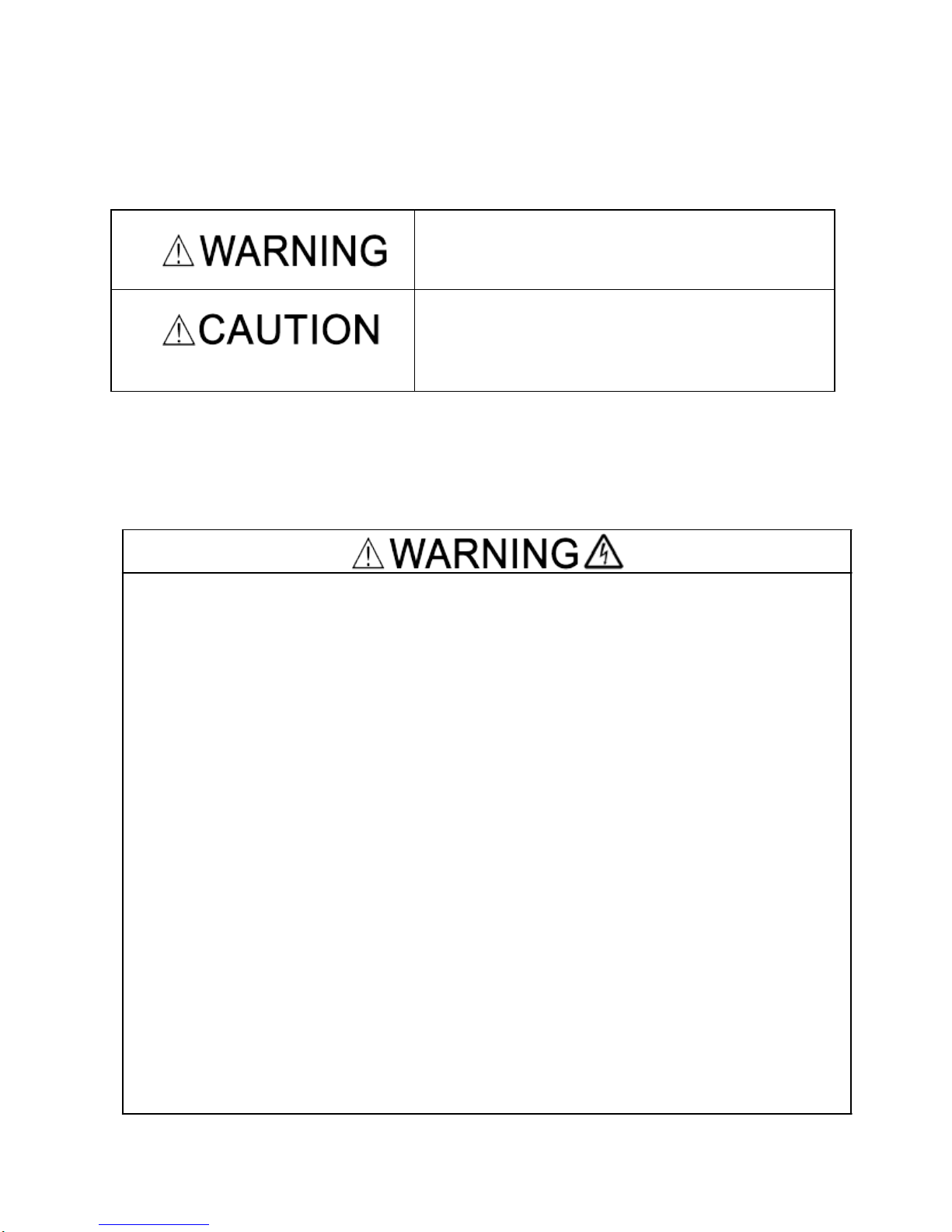
Safety precautions are classified into the following two categories in this manual.
Failure to heed the information indicated by this
symbol may lead to dangerous conditions, possibly
resulting in death or serious bodily injuries.
Failure to heed the information indicated by this
symbol may lead to dangerous conditions, possibly
resulting in minor or light bodily injuries and/or
substantial property damage.
Failure to heed the information contained under the CAUTION title can also resu lt in s erious consequences. These safety precautions are of utmost importance and must be observed at all times.
Operation
Be sure to install the terminal block cover before turning the power on. Do not remove the
cover while power is applied.
Otherwise electric shock could occur.
Do not operate switches with wet hands.
Doing so could cause electric shock.
If the retry function has been selected, the inverter may automatically restart and drive
the motor depending on the cause of tripping.
(Design the machinery or equipment so that human safety is ensured after restarting.)
If the stall prevention function (current limiter), automatic deceleration, and overload
prevention control have been selected, the inverter may operate at an acceleration
/deceleration time or frequency different from the set ones. Design the machine so that
safety is ensured even in such cases.
Otherwise an accident could occur.
The STOP key is only effective when function setting (Function code F02) is established
to enable the STOP key. Prepare an emergency stop switch separately. If you disable
the STOP key priority function and enable operation by external commands, you cannot
emergency-stop the inverter using the STOP key on the built-in keypad.
If an alarm reset is made with the operation signal turned on, a sudden start will occur.
Ensure that the operation signal is turned off in advance.
Otherwise an accident could occur.
1
Item
Specifications
Site location Indoors
Ambient
temperature
-10 to +50°C (IP20) (Note 1)
Relative
humidity
5 to 95% (No condensation)
Atmosphere
The inverter must not be exposed to dust,
direct sunlight, corrosive gases, flammable
gas, oil mist, vapor or water drops.
(Note 2)
The atmosphere can contain only a low
level of salt.
(0.01 mg/cm
2
or less per year)
The inverter must not be subjected to
sudden changes in temperature that will
cause condensation to form.
Altitude 1,000 m max. (Note 3)
Atmospheric
pressure
86 to 106 kPa
Vibration
3 mm (Max. amplitude) 2 to less than 9 Hz
9.8 m/s
2
9 to less than 20 Hz
2 m/s
2
20 to less than 55 Hz
1 m/s
2
55 to less than 200
Hz
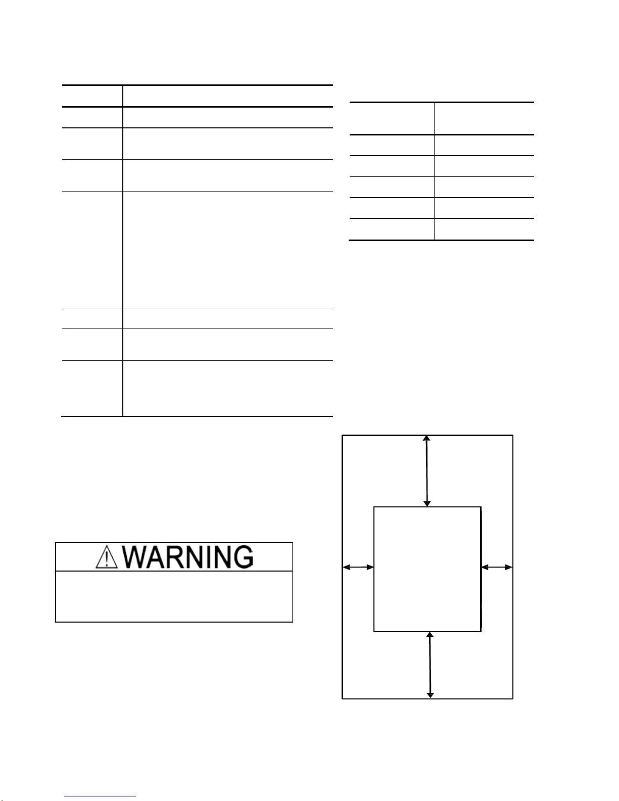
1. Operating Environment
Install the inverter in an environment that satisfies the requirements listed in
Table 1.1 Environmental Requirements
Table 1.2 Output Current Derating Factor
in Relation to Altitude
2. Installing the Inverter
(1) Mounting base
The temperature of the heat sink may rise up to
approx. 90°C during operation of the inverter, so the
inverter should be mounted on a base made of
material that can withstand temperatures of this
level.
Install the inverter on a base made of metal or
other non-flammable material.
A fire may result with other material.
(2) Clearances
Ensure that the minimum clearances indicated in
Figure 2.1 are maintained at all times. When
installing the inverter in the panel of your system,
take extra care with ventilation inside the panel as
the temperature around the inverter tends to
increase.
Figure 2.1 Mounting Direction and
Required
Clearances
Altitude
Output current
derating factor
1000 m or lower
1.00
1000 to 1500 m
0.97
1500 to 2000 m
0.95
2000 to 2500 m
0.91
2500 to 3000 m
0.88
(Note 1)
When inverters are mounted side-by-
side without any gap between them, the
ambient temperature should be within the
range from -10 to +40°C.
(Note 2)
Do not install the inverter in an
environment where it may be exposed to
cotton waste or moist dust or dirt which will
clog the heat sink in the inverter. If the
inverter is to be used in such an
environment, install it in the panel of your
system or other dustproof containers.
(Note 3)
If you use the inverter in an altitude
above 1000 m, you should apply an output
current derating factor as listed in Table 2.2.
Left
10 mm
Right
10 mm
Bottom 100 mm
FVR-Micro
Top 100 mm
2
When mounting two or more inverters
When mounting two or more inverters in the same unit or panel, basically lay them out s ide by
side. As long as the ambient temperature is 40°C or lower, inverters can be mounted side by
side without any clearance between them. When the inverters necessarily mounted one above
the other be sure to separate them with a partition plate or the like so that any heat radiating
from an inverter will not affect the one(s) above.
(3) Mounting direction
Secure the inverter to the mounting base with four screws or bolts (M4) so that the FVR-Micro logo
faces outwards. (FVR0.4AS1S-7 and
FVR0.75AS1S-7 use t wo screws or bolts.) Tighten those
screws or bolts perpendicular to the mounting base. (Maximum torque is 0.6N∙m)
Do not mount the inverter upside down or horizontally. Doing so will reduce the
heat dissipation efficiency of the inverter and cause the overheat protection function to
operate, so the inverter will not run.
Prevent lint, paper fibers, sawdust, dust, metallic chips, or other foreign materials from getting
into the inverter or from accumulating on the heat sink.
This may result in a fire or accident.
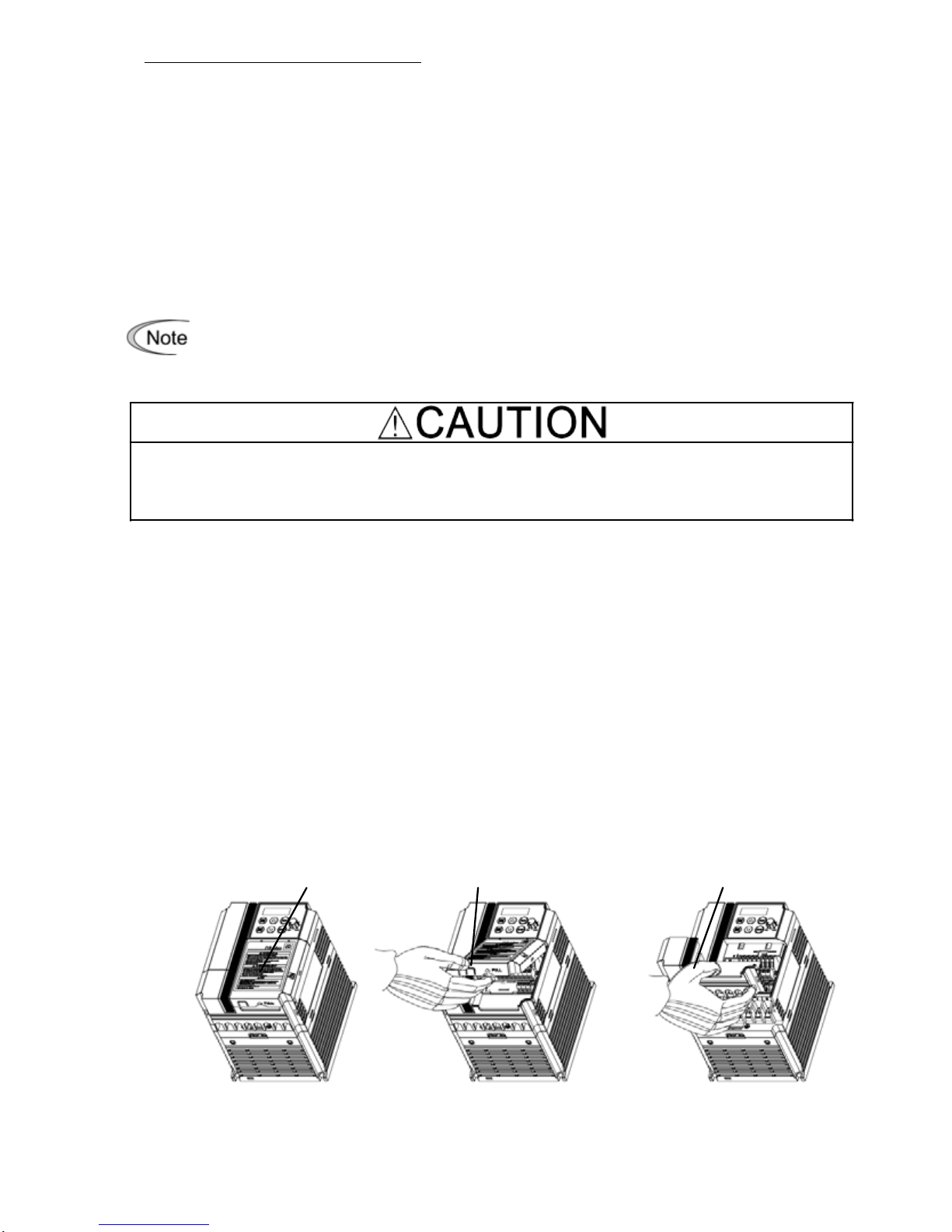
3. Wiring
Follow the procedure below. (In the following description, the inverter has already been installed.)
3.1 Removing and mounting the terminal block covers
(1) Loosen the screw securing the control circuit terminal block cover.
(2) Insert your finger in the cutout (near "PULL") in the bottom of the control circuit terminal
block cover, and then pull the cover towards you.
(3) Hold both sides of the main circuit terminal block cover between thumb and forefinger and
slide it towards you.
(4) After performing wiring, mount the main circuit terminal block cover and control circuit
terminal block cover in the reverse order of removal.
[ Removing the Terminal Block Covers ]
Control circuit terminal
block cover screw
Control circuit terminal
block cover
Main circuit terminal
block cover
3
3.2 Terminal arrangement and screw specifications
The figures below show the arrangement of the main and control circuit terminals which differ
according to inverter type. The two terminals prepared for grounding, which are indicated by the
symbol G in Figures A to C, make no distinction between the power supply side (primary circuit)
and the motor side (secondary circuit).
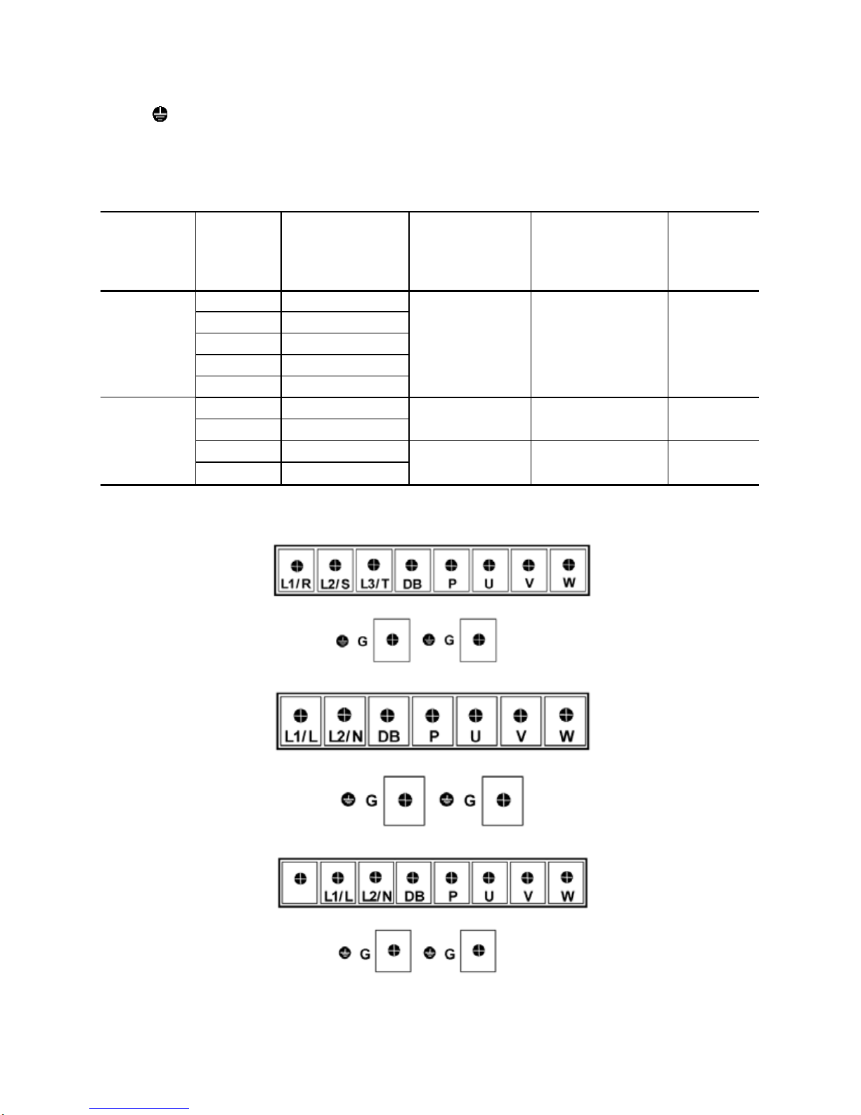
(1) Arrangement of the main circuit terminals
Table 3.1 Main Circuit Terminals
Power supply
voltage
Nominal
Ap
plied
m
otor(kW)
Inverter type
Terminal screw
size
Tightening torque
(N·m)
Refer to:
Three- phase
400 V
0.4
FVR0.4AS1S-4
M4 1.2 Fig A
0.75
FVR0.75AS1S-4
1.5
FVR1.5AS1S-4
2.2
FVR2.2AS1S-4
3.7
FVR3.7AS1S-4
Single- phase
200 V
0.4
FVR0.4AS1S-7
M3 0.5 Fig B
0.75
FVR0.75AS1S-7
1.5
FVR1.5AS1S-7
M4 1.2 Fig C
2.2
FVR2.2AS1S-7
Figure A
Figure B
Figure C
4
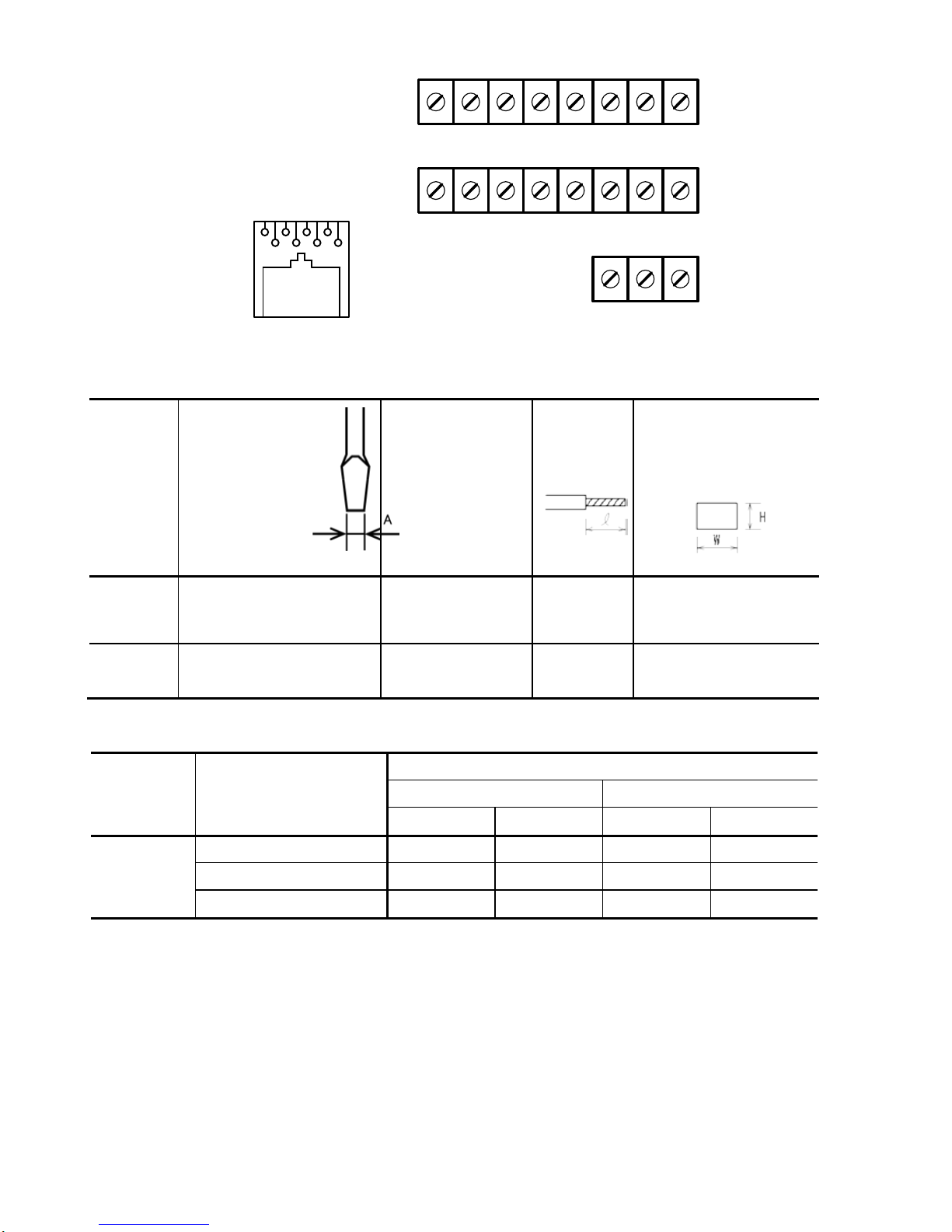
(2) Arrangement of the control circuit termi nal s (c om m on to all FVR-Micro models)
Y1 Y1E FMA C1 PLC X1 X2 X3
DX+ DX- 13 12 11 FWD REV CM
30A 30B 30C
8 7 6 5 4 3 2 1
1 : 5V
2 : Ground
3 : NC
4 : DX5 : DX+
6 : NC
7 : Ground
8 : 5V
Screw size : M2.5 Tightening torque : 0.4Nm
Table 3.2 Control Circuit Terminals
Terminal
symbol
Screwdriver
(Shape of
tip,
B x A)
Thickness of tip: B
Allowable wire size
Bare wire
length
Ferrule
terminal*
Opening dimension in
the terminal
block
First row in
the box
[Y1]~[X3]
Flat screwdriver
(0.6 x 3.5 mm)
AWG22 to AWG14
(0.34 to 2.1 mm
2
)
4.5 to 5 mm 5 (W) x 2.5 (H) mm
Other than
the above
Flat screwdriver
(0.6 x 3.5 mm)
AWG24 to AWG14
(0.25 to 2.1 mm
2
)
5 to 6 mm 2.3 (W) x 2.5 (H) mm
Table 3.3 Recommended Ferrule Terminals
Screw size Wire
size
Type
(216- )
With insulated collar Without insulated collar
Short type Long type Short type Long type
M2 or M2.5
AWG22 (0.34 mm2 )
322 302 152 132
AWG20 (0.50 mm2 )
221
201
121
101
AWG18 (0.75 mm2 )
222 202 122 102
The length of bared wires to be inserted into ferrule terminals is 5.0 mm or 8.0 mm for the short
or long type, respectively.
The following crimping tool is recommended: Variocrimp 4 (Part No. 206-204).
5
3.3 Recommended wire sizes
Table 2.6 lists the recommended wire sizes. The recommended wire sizes for the main circuit
terminals for an ambient temperature of 50°C are indicated for two types of wire: HIV single wire (for
the maximum allowable temperature 75°C).
Table 3.4 Recommended Wire Sizes
Power supply
voltage
Nomi-
nal
applied
motor
(kW)
Inverter type
*1
Recommended wire size (mm
2
)
Main
Control
circuit
Main circuit power
input
[L1/R, L2/S, L3/T]
[L1/L,
L2/N]
Grounding
[ G]
Inverter
output
[U, V, W]
Braking
resistor
[P, DB]
w/o DCR
Three-phase
400 V
0.4
FVR0.4AS1S-4
2.0(2.0)
0.5
0.75
FVR0.75AS1S-4
1.5
FVR1.5AS1S-4
2.2
FVR2.2AS1S-4
3.7
FVR3.7AS1S-4
Single-phase
200 V
0.4
FVR0.4AS1S-7
2.0(2.0)
2.0(2.0)
2.0(2.5)
0.75
FVR0.75AS1S-7
1.5
FVR1.5AS1S-7
2.0(3.5)
2.2
FVR2.2AS1S-7
5.5(5.5)
*1 Use crimp terminals covered with an insulated sheath or insulating tube. Recommended wire sizes are for
HIV/IV (PVC in the EU).
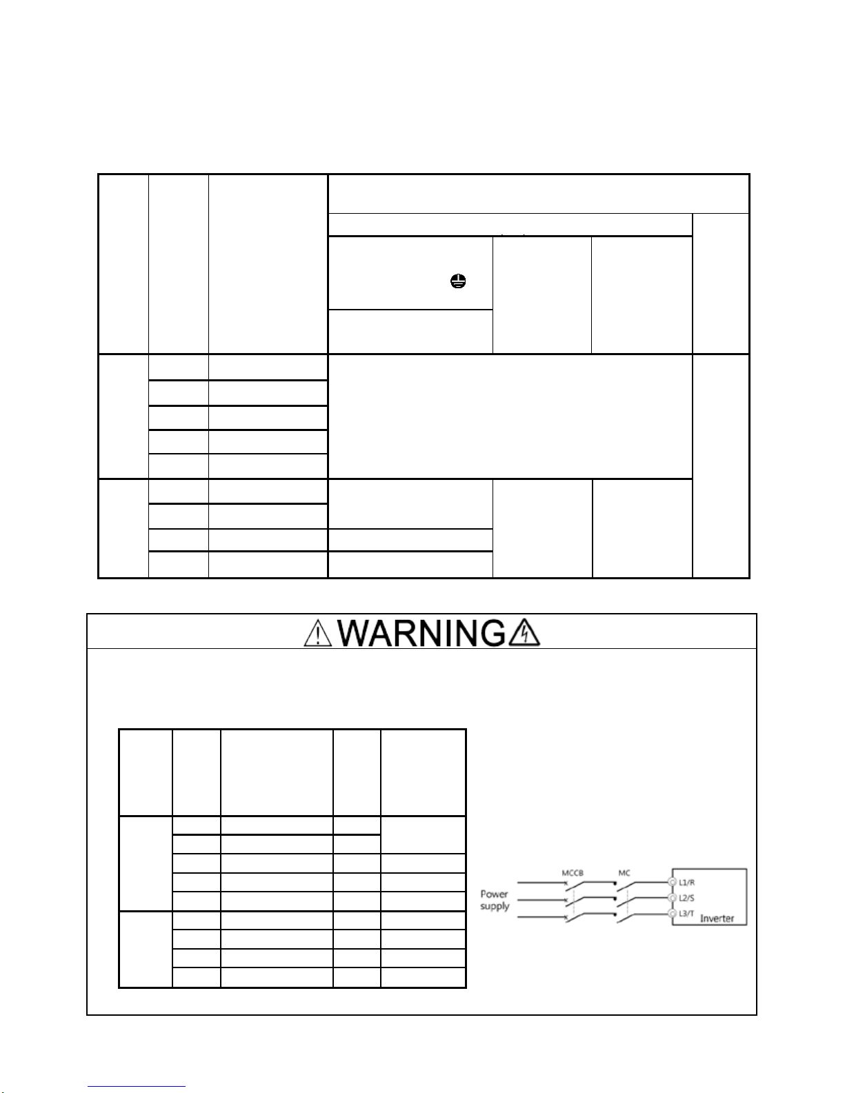
To prevent the risk of hazardous accidents that could be caused by damage of the inverter,
install the specified MCCB in the supply side (primary side) according to the following tables.
- Breaking capacity: Min. 10 kA
- Rated voltage: Min. 500 V
Power
supply
voltage
Appli-
cable
motor
rating
(kW)
Inverter type
Fuse
Rating
(A)
Rated
Current(A)
of MCCB
(w/o DCR)
Three-
phase
400 V
0.4
FVR0.4AS1S-
4
3
6
0.75
FVR0.75AS1S
-4
6
1.5
FVR1.5AS1S
-4
10
10
2.2
FVR2.2AS1S
-4
15
15
3.7
FVR3.7AS1S
-4
20
20
Single-
phase
200 V
0.4
FVR0.4AS1S
-7
10
10
0.75
FVR0.75AS1S
-7
15
15
1.5
FVR1.5AS1S
-7
30
20
2.2
FVR2.2AS1S
-7
40
35
6
3.4 Wi ring for main circuit terminals and grounding terminals
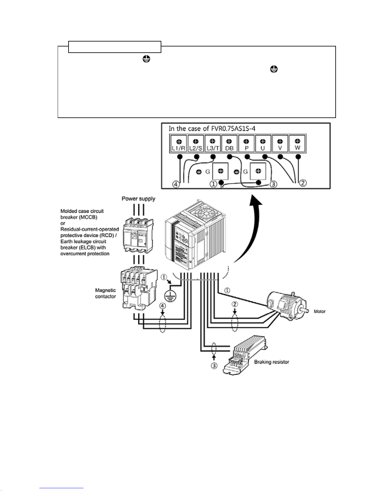
Follow the procedure below. Figure 3.1 illustrates the wiring procedure with peripheral equipment.
Wiring procedure
①
Grounding terminal G*
1
② Inverter output terminals (U, V, and W) and grounding terminal G*1
③ Braking resistor connection terminals (P and DB)*2
④ Main circuit power input terminals (L1/R, L2/S and L3/T) or (L1/L and L2/N)
*
1
Use either one of these two grounding terminals on the main circuit terminal block.
*
2
Perform wiring as necessary.
Figure 3.1 Wiring procedures for Peripheral Equipment
7
The wiring procedure for the FVR0.75AS1S-4 is given below as an example. For other inverter
types, perform wiring in accordance with their individual terminal arrangement.
①
Grounding terminal ( G)
Be sure to ground either of the two grounding terminals for safety and noise reduction. It is
stipulated by the Electric Facility Technical Standard that all metal frames of electrical equipment
must be grounded to avoid electric shock, fire and other disasters.
Grounding terminals should be grounded as follows:
1) Ground the inverter in compliance with the national or local electric code.
2) Connect a thick grounding wire with a large surface area. Keep the wiring length as short as
possible.
②
Inverter output terminals, U, V, W and grounding terminal ( G)
1) Connect the three wires of the three-phase motor to terminals U, V, and W, aligning phases
each other.
2) Connect the grounding wire of terminals U, V, and W to the grounding terminal ( G).
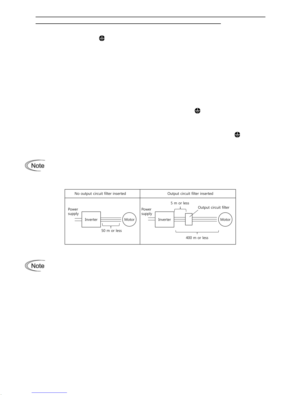
The wiring length between the inverter and motor should not exceed 50 m. If it exceeds
50 m, it is recommended that an output circuit filter (option) be inserted.
Do not use one multicore cable to connect several inverters with motors.
Do not connect a phase-advancing capacitor or surge absorber to the inverter’s output
lines (secondary circuit).
If the wiring length is long, the stray capacitance between the wires will increase,
resulting in an outflow of the leakage current. It will activate the overcurrent protecti on,
increase the leakage current, or will not assure the accuracy of the current display. In
the worst case, the inverter could be damaged.
If more than one motor is to be connected to a single inverter, the wiring length should
be the total length of the wires to the motors.
8

Driving 400 V series motor
If a thermal relay is installed in the path between the inverter and the motor to protect
the motor from overheating, the thermal relay may malfunction even with a wiring
length shorter than 50 m. In this situation, add an output circuit filter (option) or lower
the carrier frequency (Function code F26: Motor sound (Carrier frequency)).
If the motor is driven by a PWM-type inverter, surge voltage that is generated by
switching the inverter component may be superimposed on the output voltage and may
be applied to the motor terminals. Particularly if the wiring length is long, the surge
voltage may deteriorate the insulation resistance of the motor. Consider any of the
following measures.
- Use a motor with insulation that withstands the surge voltage.
- Connect an output circuit filter (option) to the output terminals (secondary circuits) of
the inverter.
- Minimize the wiring length between the inverter and motor (10 to 20 m or less).
③
Braking resistor terminals, P and DB
1) Connect terminals P and DB of a braking resistor (option) to terminals P and DB on the main
circuit terminal block.
2) Arrange the inverter and braking resistor to keep the wiring length to 5 m or less and twist the
two wires or route them together in parallel.
④
Main circuit power input terminals, L1/R, L2/S, and L3/T ( for thre e-phase volta ge input) or
L1/L and L2/N (for single-phase voltage i nput )
1) For safety, make sure that the molded case circuit breaker (MCCB) or magnetic contactor
(MC) is turned off before wiring the main circuit power input terminals.
2) Connect the main circuit power supply wires (L1/R, L2/S and L3/T or L1/L and L2/N) to the
input terminals of the inverter via an MCCB or residual-current-operated protective device
(RCD)/earth leakage circuit breaker (ELCB)*, and MC if necessary.
It is not necessary to align phases of the power supply wires and the input terminals of the
inverter with each other.
* With overcurrent protection
It is recommended that a magnetic contactor be inserted which can be manually
activated.
This is to allow you to disconnect the inverter from the power supply in an emergency
(e.g., when the protective function is activated) so as to prevent a failure or accident
from causing the secondary problems.
9
 Loading...