

Page 1
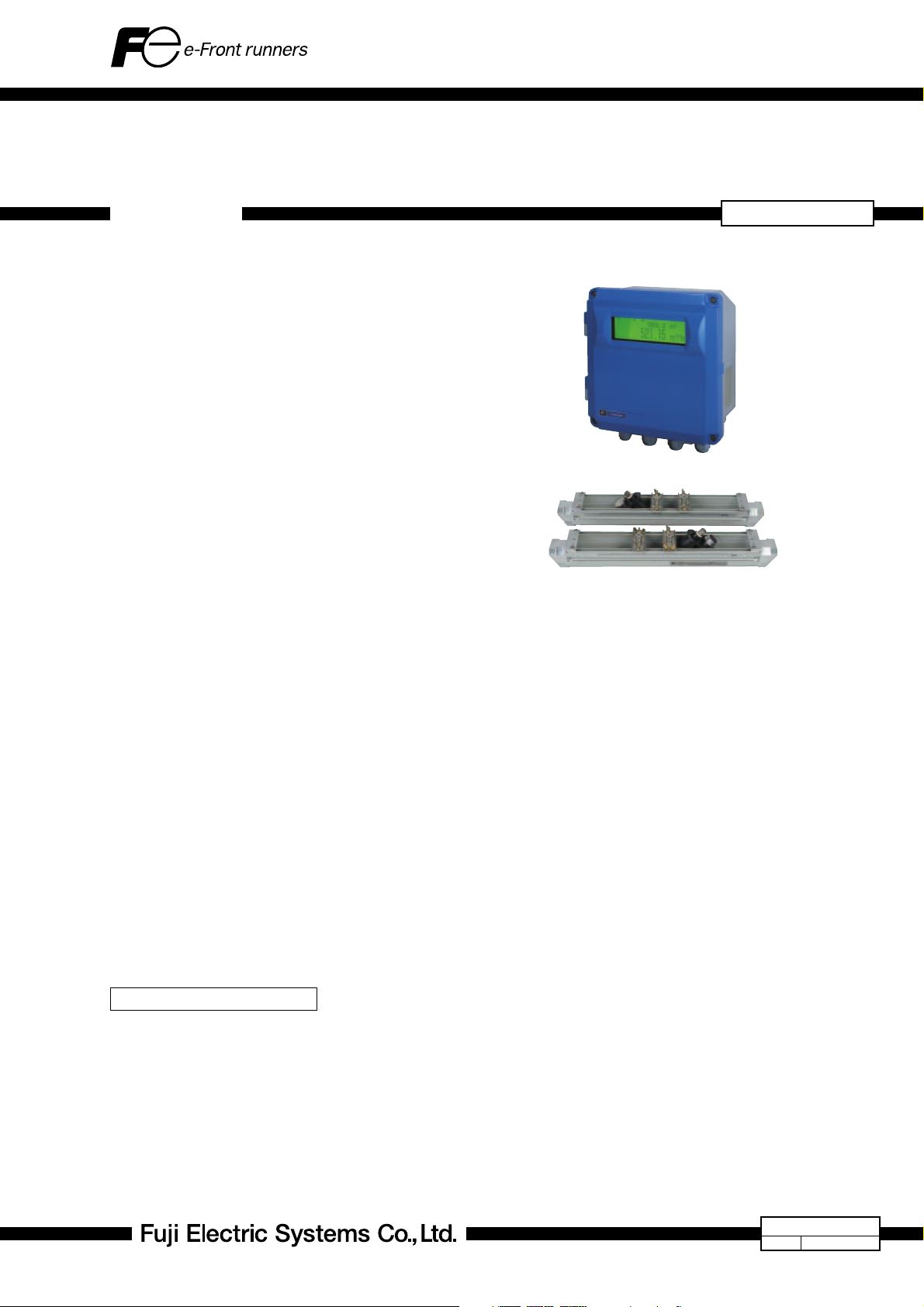
HYBRID ULTRASONIC FLOWMETER <Duosonics>
(Pulse Doppler method + Transit Time method)
DATA SHEET
This meter is the world’s first non-intrusive type ultrasonic
flowmeter utilizing Pulse Doppler method along with Transit
Time method. It enables measurement of velocity profile directly resulting in high accuracy. This makes it suitable for undeveloped flow and for short straight pipes. Pulse Doppler
method requires reflectors in the liquid and is utilized on
opaque liquids while Transit Time method requires ultrasound
penetration and is ideal for clean liquids. The new hybrid technology utilizes both methods in a complementary fashion thus
enabling a wider range of applications than it is possible now.
In addition, thanks to Fuji’s new state-of-the-art algorithm, either method can be automatically switched to accommodate
for varying fluid conditions such as concentration of particles
and/or air bubbles and flow velocity.
FEATURES
1. Automatic switchover function between Pulse Doppler method utilizing ultrasound reflection and Transit
Time method utilizing ultrasound penetration
• Applicable to various kinds of liquids with/without air
bubbles and/or solid particles
• Applicable to liquid flow that changes in nature frequently
or periodically
2. High-accuracy non-intrusive (non-contact) volumetric
flow rate measurement of liquid flow in closed pipes.
• Accuracy of 0.5% to 1% (depending on the measuring
mode and pipe size)
• Clamp-on sensor
3. Direct measurement of velocity profile in case of
Pulse Doppler method
• High accuracy of 0.5% to 1% (correction coefficient un-
necessary)
• Applicable to undeveloped flow (short straight pipe)
• Applicable to flow hovering in the transitional region be-
tween laminar flow and turbulent flow
4. High speed response: 0.2sec (pulse Doppler method)/
0.5sec (transit time method)
5. Real time monitoring of velocity profile by PC in case
of Pulse Doppler method (option)
6. Dual-path option improves performance
SPECIFICATIONS
Operational specifications
System configuration:
The system is composed of one/two detectors (Model: FSW) and one Flow transmitter
(Model: FSH), realizing single-path/two-path
measurement.
Hybrid mode or transit time mode is selectable.
In case of hybrid mode, ether Pulse Doppler
method or transit time method is automatically selected depending on conditions of
measured liquid and magnitude of velocity.
FSH, FSW, FLY
Flow transmitter
(FSH)
Detector
(FSW)
Application: Uniform liquid in which ultrasonic waves can
propagate.
Air bubble quantity: Pulse Doppler method: 0.02 to
15% of volume at 1 m/s
Transit time method: 0 to 12%
of volume at 1 m/s
Fluid temperature: -40 to +100°C (FSW12), -40 to
80°C (FSW21, FSW40,FSW50)
Type of flow: P u l se Doppler method:
axisymmetric flow in a filled
pipe.
Transit time method: well-developed turbulent or laminar
flow in a filled pipe.
Applicable flow pipe:
Material: Plastics (PVC, FRP, etc.) or
Metals (carbon steel, SS, copper, aluminum, etc.)
Pipe size: 50 to 1000 mm
(inside diameter)
Liner: Tar epoxy, mortar, etc.
Straight pipe length: Typically 10D for upstream and
5D for downstream. Refer to
JEMIS-032 in detail.
(Note) JEMIS: Japan Electric
Measuring Instruments
Manufactures' Associations Standard
Velocity: Hybrid mode: 0 to ±0.3 --- ±Maximum Velocity
(depending on pipe diameter) (Note) Maximum measurement range in Hybrid mode
(see page 4)
Transit time mode: 0 to ±0.3 --- ±32 m/s
Power supply:
100 to 240 Vac+10%/-15%, 50/60Hz or 20 to
30 Vdc
EDS6-132a
Date
Aug. 31, 2005
Page 2

FSH, FSW, FLY
Signal cable: Single-path system :
A pair of RF co-axial cables for ultrasound signals and a three-core shield cable for temperature sensor,
Two-path system: Two pairs of RF co-axial
cables for ultrasound signals and a three-core
shield cable for temperature sensor,
Maximum cable length: 150m
Temperature range : 80°C
Environment: Non-explosive environment without direct
sunlight, corrosive gas and heat radiation
Ambient temperature:
-10 to +50°C for flow transmitter,
-20 to +80°C for detector
Ambient humidity:
95%RH or less for flow transmitter, 100%RH
or less for detector
Grounding: Class D (less than 100 ohm)
Arrester: Surge absorbers for outputs and power supply
incorporated as standard
Performance specifications
Accuracy :
Pulse Doppler method :
Pipe size (inside diameter)
ø50mm to ø1000mm
(Detector FSWS12)
ø100mm to ø1000mm
(Detector: FSWS21,40,50)
Velocity
1.5 m/s to
Max. Velocity (Note)
0 m/s to 1.5 m/s
1 m/s to
Max. Velocity (Note)
0 m/s to 1 m/s
Accuracy
±0.5% of rate
±0.0075m/s
±1.0% of rate
±0.01m/s
(Note) Maximum velocity is depend on a pipe diamecer.
See Maximum measurement range in Hybrid mode
(page 4).
Transit time method :
Pipe size (inside diameter)
ø50mm to ø300mm
or less
ø300mm to ø1000mm
Velocity
2 to 32 m/s
0 to 2 m/s
1 to 32 m/s
0 to 1 m/s
Accuracy
±1.0% of rate
±0.02m/s
±1.0% of rate
±0.01m/s
Response time:
Pulse Doppler method: 0.2sec
(depending on pipe
diameter and measuring condition)
Transit time method: 0.5sec
Power consumption:
20W or less
Short-term thermal stability:
140°C, 30 min (FSWS12),
100°C, 30 min (FSWS21, FSWS40, FSWS50)
Functional specifications
Analog output: 4 to 20 mAdc (1 point)
Max. load resistance: 1k ohm
Digital output:+total, -total, alarm, acting range, flow switch
or total switch -- arbitrarily selectable
Mechanical relay contact:
1 point with socket (replaceable)
Normally closed/open selectable
Capacity:240 Vac/30 Vdc, 1 A
Total pulse: less than 1 p/s
(Pulse width: 50, 100 or 200 ms
selectable)
Transistor open collector: 2 points
Capacity: 30 Vdc, 0.1 A
Normally off/on selectable
Total pulse: less than 1000 p/s
(Pulse width: 0.5, 1, 2, 5, 10, 20,
50, 100 or 200 ms selectable)
Communication interface:
RS-232C equivalent / RS-485 (selectable)
Number of connectable units: one (RS-232C)/
up to 31 (RS-485)
Baud rate: 9600/19200/38400 bps selectable
Parity: none/odd/even selectable
Stop bit: 1 or 2 bits selectable
Distance: up to 15 m (RS-232C)/up to 1k m
(RS-485)
Data: velocity, flow rate, +total, -total, status
(standard), velocity profile (option)
Display device:
Graphic LCD (number of pixels: 240x64) with
back light,
Display language:
Japanese, English, French, German or Spanish
selectable
Velocity/Flow rate display:
Display of velocity and/or flow rate with flow
direction
Data: up to 10 digits (decimal point to be
counted as 1 digit)
Unit: Metric/English system selectable
Metric system English system
Velocity m/s ft/s
3
Flow rate
L/s, L/min, L/h, L/d,
kL/h, ML/d, m
3
m
/min, m3/h, m3/d,
3
km
/d, Mm3/d, BBL/s,
3
/s,
BBL/min, BBL/h,
kBBL/d, MBBL/d
ft
/s, ft3/min, ft3/h,
3
Mft
/d, gal/s, gal/min,
gal/h, Mgal/d, BBL/s,
BBL/min, BBL/h,
BBL/d, kBBL/d,
MBBL/d
Note: “gal” means US gal.
Total display: Display of forward or reverse total
Data: up to 10 digits (decimal point to be
counted as 1 digit)
Unit: Metric/English system selectable
Metric system English system
3
ft
Total
mL, L, m3, km3, Mm3,
mBBL, BBL, kBBL
, kft3, Mft3, gal, kgal,
mBBL, BBL, kBBL,
ACRf
Configuration:
Fully configurable on keyboard by menu-driven
software
Zero adjustment:
Set zero/Clear available. (transit time method)
Damping: 0 to 100s (every 0.1s) configurable for analog
output and display
Low flow cut off:
0 to 5 m/s configurable
2
Page 3
Alarm: Hardware fault/process fault can be tied to
digital output
Burnout: Analog output: Hold/Upper limit/Lower limit/
Zero/Not-used selectable
Total: Hold/Count selectable
Timer: 0 to 900s (every 1s) configurable
Bi-directional range:
Forward and reverse ranges configurable independently
Hysteresis: 0 to 20% of working range
configurable
Working range applicable to digital output
Auto-2 ranges:
Forward 2 ranges configurable independently
Hysteresis: 0 to 20% of working range
configurable
Working range applicable to digital output
Flow switch: Lower and upper switching points
configurable independently
Acting point applicable to digital output
Total switch: +total switching point configurable
Acting point applicable to digital output
Physical specifications
Enclosure protection:
Flow Transmitter: IP67,
Detector: IP67
Mounting: Flow Transmitter: wall mount
Detector: clamped on pipe surface
Acoustic coupler:
Silicon compound (RTV)
Material: Flow Transmitter: aluminum alloy
Detector: PBT for housing, aluminum alloy for
frame and SS for fastening belt
Sensor cable(FLY6):
RF coaxial cable (double shielded)
External sheath: Black flame-resistant vinyl
External diameter: About 7.3 mm
Terminal treatment: Water-resistant BNC con-
nector (detector side), M3.5 amplifier
terminal (converter side)
Weight: About 90 g/m
Temperature sensor cable(FLY7):
3-core shield cable
External sheath: Gray flame-resistant vinyl
External diameter: About 6.9 mm
Terminal treatment: Round waterproof con-
nector (detector side), M3.5 amplifier
terminal (converter side)
Weight: About 56 g/m
Dimensions: Flow Transmitter : H240 x W247 x D134 mm
Detector: H70 x W57 x L360 mm (FSWS12)
H72 x W57 x L540 mm (FSWS21)
H90 x W85 x L640 mm (FSWS40)
H82 x W71 x L258 mm (FSWS50)
Mass: Flow Transmitter: 5 kg
Detector: 1.7 kg (FSWS12), 1.9 kg (FSWS21),
5 kg (FSWS40), 1.5 kg (FSWS50)
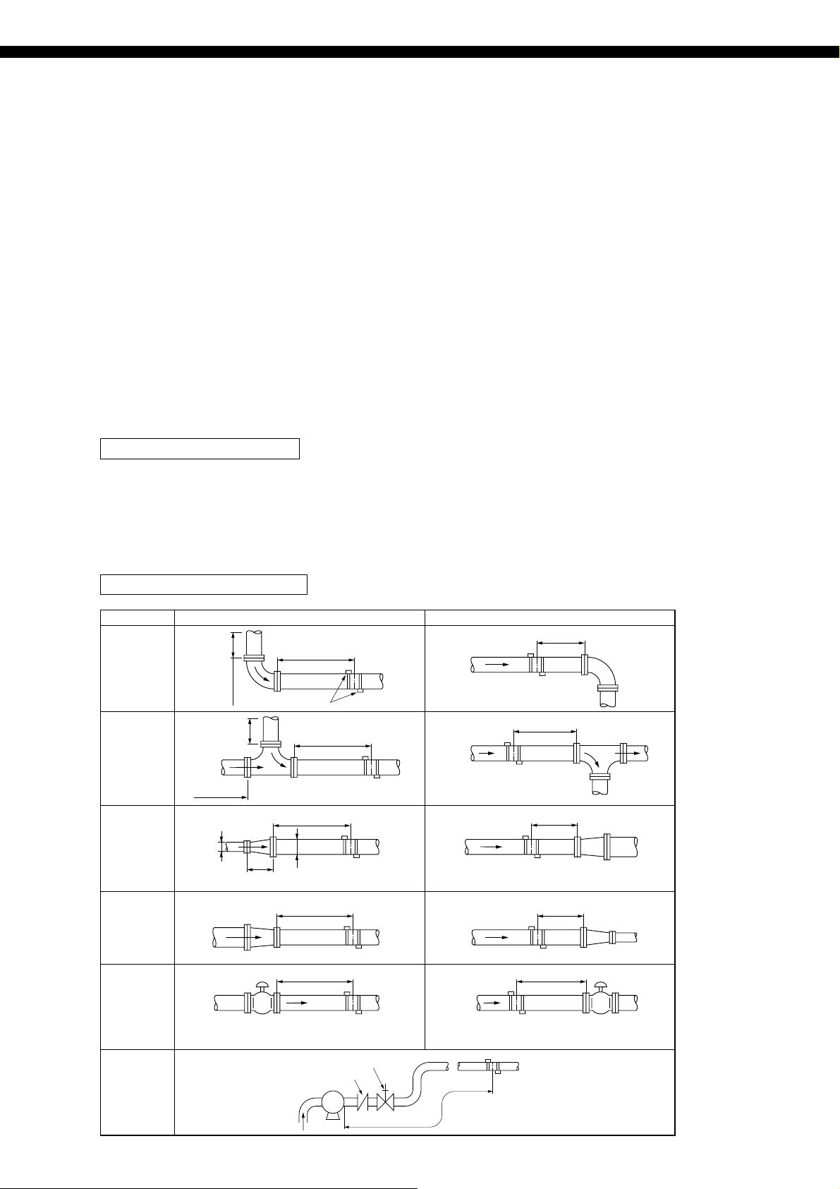
Conditions on straight pipe
( D : Inside diameter of pipe)
Classification Upstream side Downstream side
L≧5D
L≧10D
90° bend
Tee
Diffuser
Reducer
10D or more
10D
10D or more
or
0.5D
more
or
≧1.5D
more
Detector
L≧50D
L≧30D
D
L≧10D
L≧30D
L≧10D
L≧5D
L≧5D
L≧10D
Various Valve
In case that flow control valve exists on
upstream side.
Pump
(Note) The source : JEMIS-032
Stop valve
Check valve
P
In case that flow control valve exists on
downstream side.
L≧50D
3
Page 4
FSH, FSW, FLY
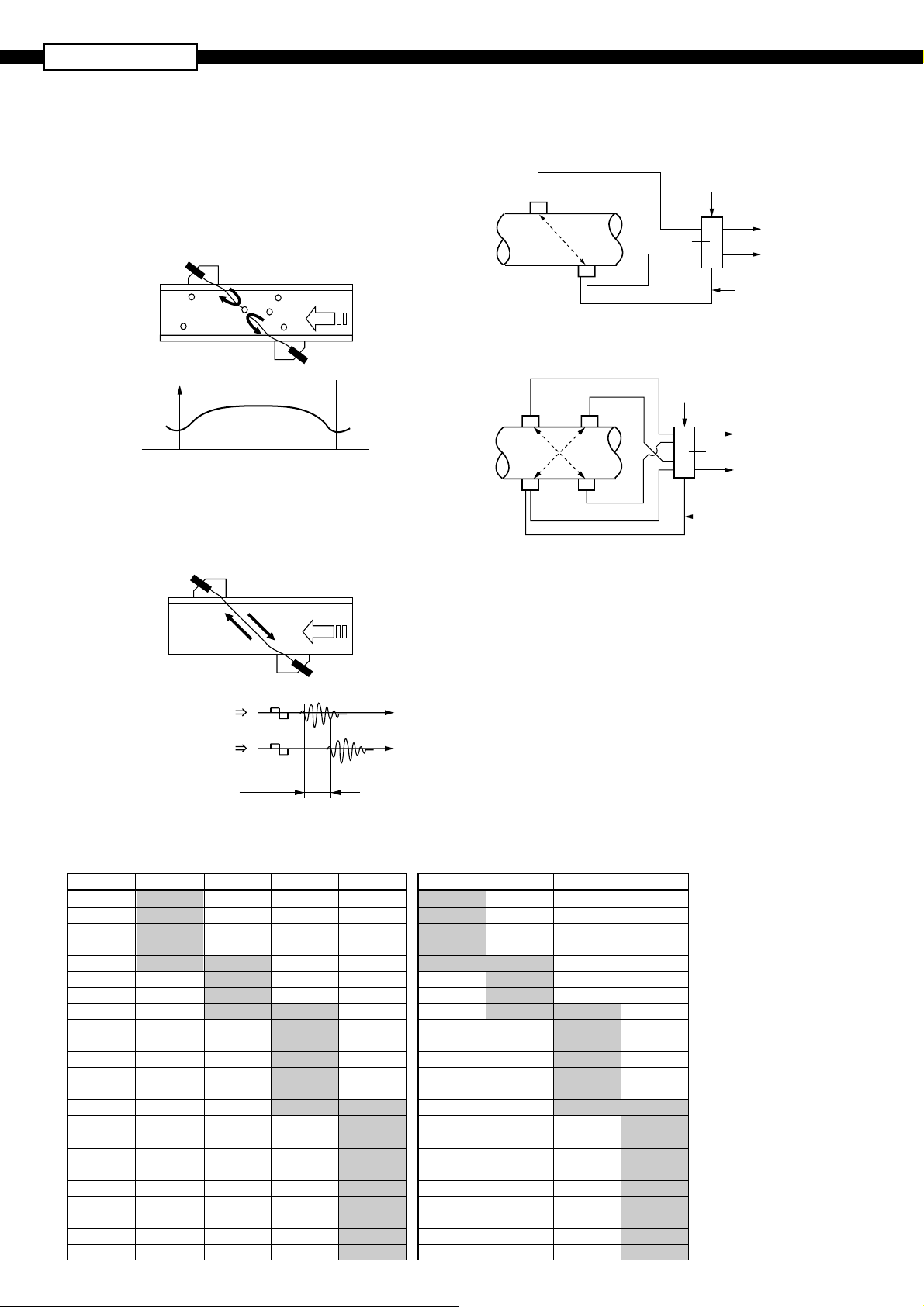
<Pulse Doppler method>
• Ultrasound pulses are transmitted into a liquid, and
flow velocity profile is found and the flow rate is measured by using the characteristics that Doppler frequency of the echo from reflectors such as air
bubbles and particles in the liquid changes according
to flow velocity.
Sensor 1
Air
bubbles
Reflection
Flow
velocity
Flow velocity
Profile 2
Piping wall Center Piping wall
Flow
velocity
Profile 1
<Transit Time method>
• Ultrasound pulses are propagated slanted both from the
upstream and downstream, and flow rate is measured by
detecting the time difference generated with the flow.
Sensor 1
Flow
Sensor 2
Block diagramMeasurement principle
(1) Single path system (Z method)
Cable
Detector
Flow
Transmitter
(2) 2-path system (Z method)
Cable
Detector
Power
supply
Power
supply
4 to 20mA DC
Flow
Transmitter
Contact
(Up to 3 points
are allowed.)
Temperature
sensor cable
4 to 20mA DC
Contact
(Up to 3 points
are allowed.)
Temperature
sensor cable
Flow
Sensor 2
Transmission
Sensor 2
Sensor 1
1
2
Time difference ∆T
Receiving
Maximum measurement range in hybrid mode
When stainless steel is selected as pipe material, nominal wall thickness is Sch20s, and the fluid is water
<Maximum measurable flow velocity>
Caliber
1000A 1.76
FSWS12
50A
65A 4.99
80A 4.40
90A 3.92
100A 3.45 6.95
125A 5.86
150A 5.04
200A 3.96 7.59
250A 6.26
300A 5.32
350A 4.82
400A 4.25
450A 3.80
500A 3.54 3.54
550A 3.14
600A 2.89
650A 2.69
700A 2.50
750A 2.34
800A 2.19
850A 2.07
900A 1.95
FSWS21 FSWS40 FSWS50
6.04
Unit: m/s
<Maximum measurable flow rate>
FSWS12
FSWS21 FSWS40 FSWS50
48.5
67.8
81.8
97.1
110.2 222.0
279.2
343.2
462.8 887
1,146
1,404
1,572
1,831
2,091
2,393 2,393
Unit: m
2,587
2,850
3,067
3,325
3,590
3,839
4,112
4,357
4,852
3
/h
4
Page 5

CODE SYMBOLS
<Flow transmitter>
12345678 9101112
F
SH Y YY
1S
E
Y
A
Y
1
4
1
S
Y
Y
Description
Type (4th digit)
Standard
Velocity profile output (5th digit)
None
Available
Use (6th digit)
Single path or Changeover two-path (Note)
2 sets of detectors and coaxial cables
Note:
(FLY6) needed for two-path system.
Power supply (7th digit)
100 to 240 Vac, 50/60 Hz
20 to 30 Vdc
Modification No. (8th digit)
Mark 1
Case structure (9th digit)
IP67
Conduit connection (10th digit)
G1/2 (female screw) with water-proof
connection
For use with explosion-proof detector
None
Parameter setting, Tag Plate (12th digit)
None
Y
With setting
A
With setting and Tag Plate
B
With Tag Plate
C
(11th digit)
<Signal cable>
12345678
F
LY
1
6
7
5
0
0
0
1
0
5
1
0
0
2
0
5
2
0
0
3
0
5
3
0
0
4
0
5
4
0
0
5
0
5
5
0
0
6
0
5
6
0
0
7
0
5
7
0
0
8
0
5
8
0
0
9
0
5
9
0
0
0
1
0
1
1
0
2
1
0
3
1
0
4
1
0
5
1
1
Description
Kind of cable (4th digit)
Coaxial cable (for ultrasonic sensors)
Three-core cable (for temperature sensor)
Cable length (5th to 7th digit)
5m
10m
15m
20m
25m
30m
35m
40m
45m
50m
55m
60m
65m
70m
75m
80m
85m
90m
95m
100m
110m
120m
130m
140m
150m
Length in m to be designated with 3 digits
Modification No. (8th digit)
Mark 1
<Detector>
12345678 91011
F
SSW0Y
1
S
1
2
2
1
4
0
5
0
0
1
Y
(Note) Select silicone compound (A) for acoustic
Description
Type (4th digit)
Standard
Kind of detector (5th and 6th digit)
Small diameter detector (φ 50 to 100 mm)
Small size detector (φ 100 to 200 mm)
Middle size detector (φ 200 to 500 mm)
Large size detector (φ 500 to 1000mm)
Use (7th digit)
Standard (IP67)
Modification No. (8th digit)
Mark 1
Signal cable (9th digit)
None
Acoustic coupler (10th digit) (Note)
Y
None
A
Silicone compound
Option (11th digit)
None
Y
Tag Plate
A
coupler in ordinary cases. Silicon compound is
supplied in a tube (150g). If one or more
detectors one ordered, silicon compound may
be selected onece every 5 orders or so.
Loader software for PCs
Equipped as standard
• Works on PC/AT compatible machines.
• Operation on PC98-series machines (NEC) cannot be
guaranteed.
• Operation on self-made PCs or shop-brand PCs cannot be
guaranteed.
•Major functions: Setting/changing of various parameters
for the main unit
If no flow velocity profile output is selected,
the following functions are not available.
“Detailed setting” and “flow velocity profile
display” in pulse Doppler measurement
“Detailed setting” and “ receved signal display” in Transit time measurement
• O/S: Windows2000/XP
• Memory requirement: 128MB or more
• Disk unit: Windows2000/XP-compatible CD-ROM drive
• Hard disk drive capacity: Free space of 52MB or more
Note: PC loader communication cable
(type ZZP*FSH TK4H6253) is separately required.
Detector frame installation fixture
Installation fixture is provided to facilitate the positioning of
the frame to the piping.
Select a desired type from the following according to the detector to be used.
Type
ZZP FSW TK7M7071C1
Applicable detector
FSWS12
ZZP FSW TK7M7071C2 FSWS21
ZZP FSW TK7M7071C3 FSWS40
Note: The installation fixture cannot be used for detector type
FSWS50, which is not provided with a frame.
5
Page 6

FSH, FSW, FLY
OUTLINE DIAGRAM
(Unit:mm)
<Flow transmitter (type: FSH)>
3
134
352
332
4-
φ
9
240
Duosonics
14
3333
Mtg. plate
(273) 30
72
233
CONNECTION DIAGRAM
Power supply terminals (AC)
2344
L1N
100 to 240V AC
Power supply terminals (DC)
123
+–
20 to 30V DC
2
1
HF
UP STR
34
HF
GND
DOWN STR
LINE1 LINE2
GND
56
HF GND
UP STR
HF GND
DOWN STR
30 30 30 24
48 48 48
B
Cable
(Black)
To temp sensor
78
* Use LINE1 terminals in case of single measuring path.
Cable
(Black)
312
BA
Cable
(Yellow/
Green)
1
DO1
SERIAL
SERIAL
No. RS485
4
5
6
2
3
–+
+
DO2
7654
+
Iout
TRX2 (
–
)
TRX1 (
+
)
SHILD
4–56–7
+
DO3
98
–
RS232C
TXD
RXD
COM
6
Page 7

OUTLINE DIAGRAM
(Unit:mm)
<Detector (type: FSWS12, 21)>
BNC Connector
Temp sensor
Sensor unit
Absorber unit
Frame
Type
FSWS12
FSWS21
W
(H)L
Pipe size (mm)
φ50 to φ100 360
φ
100 to φ200 540
L
WH
5770
5772
<Detector (type: FSWS40)>
BNC Connector
Temp Sensor
Sensor unit
640
Absorber unit
Frame
85
(90)
7
Page 8

FSH, FSW, FLY
OUTLINE DIAGRAM
(Unit:mm)
<Detector (type: FSWS50)>
BNC Connector
Temp sensor
Sensor unit
258
Absorber unit
71
82
8
Page 9

<Signal cable (type: FLY6)> <Signal cable (type: FLY7)>
L ± 1 (m)
φ11
φ7.3
φ15
BNC Connector
φ21.5
Connector
φ6.9
L ± 1 (m)
3-
φ
6.6
SCOPE OF DELIVERY
• Flow transmitter (Type: FSH):
Flow transmitter
CD-ROM (Instruction manual,
Loader software)
•Detector (Type: FSW): Sensor unit
Mounting belt
Silicon compound (option)
• Signal cable (Type: FLY6): Cable (2 wires)
3-
φ
6.6
ITEMS DESIGNATED ORDERING
• Flow transmitter code symbols
• Detector code symbols
• Signal cable code symbols
• Signal cable (Type: FLY7): Cable for temperature sensor (1)
9
Page 10

FSH, FSW, FLY
<Parameter specification table>
Outer diameter1
2
3
4
5
6
7
Pipe material
Wall thickness
Lining material
Lining thickness
PiPing specificationOutput setting
Kind of Fluid
Range unit
Setting itemNo.
10.00 to 6200.00mm
(0.393 to 244.100 inch)
12 menus
Settable range Initial value Settable value
60.00mm
(2.362 inch)
PVC
Carbon steel, Stainless steel, PVC, Copper,
[mm, inch]
Castiron, Aluminum, FRP, Ductileiron, PEEK,
Pipe S.V. : 1000 to 3700m/s
(3280 to 12140 ft/s)
0.10 to 100.00mm
(0.003 to 3.940 inch)
8 menus
Lining S.V. : 1000 to 3700m/s
(3280 to 12140 ft/s)
0.01 to 100.00mm
4.00mm
(0.157 inch)
No lining
PVDF, Acrylic
Others (Sound velocity : [m/s, ft/s])
[mm, inch]
No lining, Tar epoxy, Mortar, Rubber,
Teflon, Pyrex glass, PVC,
Others (Sound velocity : [m/s, ft/s])
[mm, inch]
(0.000 to 3.940 inch)
17 menus
Water
Water, Seawater, DIST. water, Ammonia,
Alcohol, Benzene, Bromide, Ethanol, Glycol,
Kerosene, Milk, Methanol, Toluol,
Fluid S.V. : 500 to 2500m/s
(1641 to 8203 ft/s)
Kinematic viscosity :
0.001 to 999.9999 x 10
-6m2
(0.0107 to 10763.9088 x 10
19 menus
/s
-6ft2
/s)
m/s
(ft/s)
Lube oil,
Fuel oil, Petrol,
Others (Sound velocity : [m/s, ft/s])
(Kinematic viscosity [x10
m/s, L/s, L/min, L/h, L/d, kL/d, ML/d, m
3
m
/min, m3/h, m3/d, km3/d, Mm3/d, BBL/s,
BBL/min, BBL/h, BBL/d, KBBL/d, MBBL/d,
3
(ft/s, ft
/s, ft3/min, ft3/h, ft3/d, kft3/d, Mft3/d,
-6m2
/s, ft2/s])
3
/s,
gal/s, gal/min, gal/h, gal/d, kgal/d, Mgal/d,
BBL/s, BBL/min, BBL/h, BBL/d, kBBL/d,
MBBL/d)
8
9 In terms of flow velocity 0.00 ···
Range type
Full scale or
Full scale 1
4 menus
±0.30 to ±32.00m/s
(±0.98 to ±104.98 ft/s)
Full scale 210 In terms of flow velocity 0.00 ···
±0.30 to ±32.00m/s
(±0.98 to ±104.98 ft/s)
Output burnout14 5 menus Hold
(0.00 to 16.40 ft/s)
in terms of flow velocity
1 : Display kind19 7 menus Flowrate (m3/s)
2 : Display kind20 7 menus Flow velocity (m/s)
Display setting
Single
2.00m/s
(6.56 ft/s)
4.00m/s
(13.12 ft/s)
0.00m/s
(0.00 ft/s)
Single, Auto 2, Bi-dir, Bi-dir Auto 2
[ ]
[ ]
%Range HYS.11 0.00 to 20.0% 10.00%
%Output limit LO.12 -20 to 0% -20%
%Output limit HI.13 100 to 120% 120%
Not use, Hold, Upper, Lower, Zero
secBurnout timer15 0 to 900sec 10sec
[ ]Rate limit16 0.00 to 5.00m/s
secRate limit timer17 0 to 900sec 0sec
secDamping18 0.0 to 100.0sec 5.0sec
Flow velocity, Flowrate, Total forward,
Total reverse,
F : Total pulse, R : Total pulse, Flow rate (%)
Flow velocity, Flowrate, Total forward,
Total reverse,
F : Total pulse, R : Total pulse, Flow rate (%)
10
(0.00 to 16.40 ft/s)
in terms of flow velocity
0.01m/s
(0.03 ft/s)
[ ]Low flow cut21 0.00 to 5.00m/s
Page 11

Setting itemNo.
Settable range Initial value Settable value
Total mode22 3 menus
Total stop
Total unit23 8 menus mL
25 0.000 to 9999999999.999 0.000
F : Total preset
F : Total SW
27 0.000 to 9999999999.999 0.000
R : Total preset
Output burnout29 2 menus Hold
Pulse width 131 3 menus 50ms
Pulse width 232 9 menus 50ms
Flow sw high33 In terms of flow velocity
0.00m/s
0.00 to ±32.00m/s
(0.00 to ±104.98 ft/s)
Flow sw low34 In terms of flow velocity
4.00m/s
0.00 to ±32.00m/s
Flow switchStatus output Total
(0.00 to ±104.98 ft/s)
Total stop, Total run, Total reset
mL, L, m
ft
3
, km3, Mm3, mBBL, BBL, kBBL,
3
, kft3, Mft3, kgal, gal, mBBL, BBL, kBBL,
ACRF
[ ]Total rate24 0.000 to 999999.999 0.000
[ ]
[ ]26 0.000 to 9999999999.999 0.000
[ ]
[ ]R : Total SW28 0.000 to 9999999999.999 0.000
Not use, Hold
50, 100, 200
0.5, 1.0, 2.0, 5.0, 10.0, 20.0, 50.0, 100.0,
200.0
[ ]
[ ]
secBurnout timer30 0 to 900sec 10sec
%Flow sw HYS.35 0 to 20% 10%
Output DO136 15 menus Not use
Mode DO137 2 menus Normal
Output DO238 15 menus Not use
Mode DO239 2 menus Normal
Output DO340 15 menus
Not use
Mode DO341 2 menus Normal
Not use, Signal error, F : Total pulse,
R : Total pulse, F : Total alarm,
R : Total alarm, F : Total overflow,
R : Total overflow, Flow SW high,
Flow SW Low, Full scale2, AO range over,
Pulse range over, R : Flow direction,
Device error
Normal, Reverse
Not use, Signal error, F : Total pulse,
R : Total pulse, F : Total alarm,
R : Total alarm, F : Total overflow,
R : Total overflow, Flow SW high,
Flow SW Low, Full scale2, AO range over,
Pulse range over, R : Flow direction,
Device error
Normal, Reverse
Not use, Signal error, F : Total pulse,
R : Total pulse, F : Total alarm,
R : Total alarm, F : Total overflow,
R : Total overflow, Flow SW high,
Flow SW Low, Full scale2, AO range over,
Pulse range over, R : Flow direction,
Device error
Normal, Reverse
11
Page 12

FSH, FSW, FLY
Setting itemNo.
System unit42 2 menus
Language43 5 menus English
Settable range Initial value Settable value
Metric
Metric, English
Japanese, English, German, French,
spanish
9600BPS, 19200BPS, 38400BPSCOM. speed44 3 menus 38400BPS
45 3 menus None
COM. parity
COM. stop bit
47 2 menus RS232C
System
Serial method
Serial com.
None, Even, Odd
1 bit, 2bits46 2 menus 1 bit
RS232C, RS485
1 to 31Station No.48 31 menus 1
49
Measurement
2 menus 1 Path
1 Path, 2 Path
mode
mode
AO Definition50 3 menus Line 1
Measuremant
51 4 menus FSW12
Note1: When total pulse output has been selected for DO1, DO2 or DO3 specify total pulse value and total pulse width so that conditions 1
Sensor Type
and 2 shown below are satisfies.
Condition 1 : 1000 [In the case of DO1 and DO2]
Condition 2 :
Flow span-1*[m
total pulse value*[m
Flow span-1*[m3/s]
total pulse value*[m
3
/s]
3
]
1 [In the case of DO3]
3
]
2 × total pulse width [ms]
1000
Average, Line 1, Line 2
FSW12, FSW21, FSW40, FSW50
* In the case of 2 ranges, perform calculations using either flow span-1 or flow span-2, whichever is greater.
Caution on Safety
*Before using this product, be sure to read its instruction manual in advance.
Head Office
6-17, Sanbancho, Chiyoda-ku, Tokyo 102-0075, Japan
http://www.fesys.co.jp/eng
Instrumentation Div.
International Sales Dept.
No.1, Fuji-machi, Hino-city, Tokyo, 191-8502 Japan
Phone: 81-42-585-6201, 6202 Fax: 81-42-585-6187
http://www.fic-net.jp/eng
Information in this catalog is subject to change without notice.
Printed in Japan
 Loading...