

Page 1
Page 2

Introduction
We thank you very much for purchasing Fuji Electric’s ultrasonic flow meter.
The instruction manual concerns the installation, operation, checkup and maintenance of the Flow transmitter
(FSV) of ultrasonic flow meter. Read it carefully before operation.
First read this instruction manual carefully until an adequate understanding is acquired, and then
proceed to installation, operation and maintenance of the flow meter. Improper handling may result in an
accident or a failure.
The specifications of this flow meter are subject to change without prior notice for improvement of the
product.
Do not attempt to modify the flow meter without permission. Fuji will not bear any responsibility for a
trouble caused by such a modification. If it becomes necessary to modify the flow meter, contact our
office in advance.
This instruction manual should always be kept on hand by the operator.
After reading the manual, be sure to store it at a place easier to access.
This instruction manual should be delivered to the end user.
If the instruction manual has been lost, request another one (with charge) to our local business office.
Manufacturer: Fuji Electric Co., Ltd.
Type: Described in the nameplate put on the main body
Date of manufacture: Described in the nameplate put on the main body
Product nationality: Japan
Issued in Dec., 2012
Note
Reproduction of any part or the whole of this manual without
permission is strictly prohibited by laws.
Contents of the manual are subject to change without prior notice.
©Fuji Electric Co., Ltd. 2012
Rev. 1st edition May, 2014
Rev. 2nd edition Jun., 2016
-i-
Page 3
SAFETY PRECAUTIONS
Before using this product, read the following safety precautions and use the product correctly.
The following items are important for safe operation and must be fully observed.
These safety precautions are ranked in 2 levels; "DANGER" and "CAUTION".
Warning/Symbol Meaning
DANGER
CAUTION
The items noted under "
All the items must be fully observed.
Incorrect handling of the device may result in death or serious injury.
Incorrect handling may lead to a risk of medium or light injury, or to a risk of
physical damage.
CAUTION
" may also result in serious trouble depending on circumstances.
Caution on mounting and piping
This unit is not explosion-proof type. Do not use it in a place with explosive
DANGER
CAUTION
gases. Otherwise, it may result in serious accidents such as explosion,
fire, etc.
The unit should be installed in a place conforming to the installation
requirements noted in this instruction manual. Otherwise, it may cause
electric shocks, fire or malfunction of the unit.
Install the flow meter according to the following steps to prevent it from
damage, and to avoid error or malfunction.
During installation, make sure that the inside of the unit is free from cable
chips and other foreign objects. Otherwise, it may cause fire, failure or
malfunction.
The items under "Caution on Installation" noted in the manual must be
fully observed. Careless installation may result in trouble or malfunction of
the unit.
Auxiliary insulation is necessary for analog output (Iout) and serial
communication (RS485) of this device.
-ii-
Page 4
Cautions in wiring
When performing wiring termination to prevent output trouble caused by
CAUTION
moisture, dew condensation or water leak, follow “Section 3.3. Flow
transmitter wiring” described in this manual.
Before performing the wiring work, be sure to turn OFF the main power.
Otherwise, it may cause electric shock.
Do not perform wiring work outdoors in rainy days to prevent insulation
deterioration and dew condensation. Otherwise, it may result in trouble,
malfunction, etc.
Be sure to connect a power source of correct rating. Use of power source
out of rating may cause fire.
The unit must be grounded as specified. Otherwise, it may cause electric
shocks, malfunction, etc.
The signal cable and analog output signal cable should be wired as far
away as possible from high-voltage lines to prevent entry of noise signals
as it will cause malfunction of the unit.
To prevent malfunction of the unit, the analog output signal cable and
power cable should be wired using separate conduits.
Be careful not to touch electronic components other than the terminal
block and the fuse holder.
Electronic components can get hot during operation and cause skin burns.
Caution on maintenance and inspection
CAUTION
The unit should be inspected every day to always obtain good results of
measurements.
When measuring the insulation resistance between the power/output terminal and the
case, follow “Section 6.2.3. How to measure the insulation resistance” described in this
manual.
If the fuse is blown, detect and eliminate the cause, and then replace the fuse with a
spare. If there are no spares, replace the fuse with the one specified in this manual
“Section 6.3. How to replace the fuse ” (that must be aquired separately). Use of a fuse
other than specified or its short-circuit may cause an electric shock or fire. The fuse
should be replaced according to “Section 6.3. How to replace the fuse” described in
this manual.
Replacement of electrolytic capacitor
An electrolytic capacitor has a service life of approx. 10 years under general
operating condition (annual average ambient temperature of 30°C).
The life will be shortened by half when the temperature rises by 10°C.
Do not use capacitor beyond its life. Otherwise, electrolyte leakage or
depletion may cause odor, smoke, or fire.
For replacement, contact Fuji Electric.
Limited warranty
The warranty term of this product including accessories is one year. Please
note that this warranty does not cover the following cases where:
a) The product is improperly used.
The product is repaired or remodeled not by Fuji Electric.
b) The product is used beyond its specifications.
c) The product is damaged due to transportation or fall after purchase.
d) The product is damaged by natural disasters such as earthquake, fire,
storm and flood, thunderbolt, abnormal voltage, or as such, or their
secondary disasters.
-iii-
Page 5

Exclusion of liability for loss of opportunity
Regardless of the time period of the occurrence, Fuji Electric is not liable for
the damage caused by the factors Fuji Electric is not responsible for,
opportunity loss of the purchaser caused by malfunction of Fuji Electric
product, passive damages, damage caused due to special situations
regardless of whether it was foreseeable or not, and secondary damage,
accident compensation, damage to products that were not manufactured by
Fuji Electric,and compensation towards other operations.
Repair service and spare parts supply after product discontinuation
The discontinued models (products) can be repaired for five years from the
month of discontinuation.
Also, most spare parts used for repair are provided for five years from the
month of discontinuation. However, some electric parts may not be obtained
due to their short life cycle. In this case, repair or provision of the parts may be
difficult even within the above period.
Please contact Fuji Electric or its service providers for further information.
Service life
The service life of this product excluding limited-life parts and consumable
parts is 10 years under general operating condition (annual average ambient
temperature of 30°C).
Please note that the above mentioned life may affected by operating environment and
operating conditions of the system.
-iv-
Page 6
CAUTION ON INSTALLATION LOCATION
CAUTION
(1) A place that provides enough space for periodic inspection and wiring work.
(2) A place not exposed to direct sunshine nor inclement weather.
(3) A place free from excessive vibration, dust, dirt and moisture.
(4) A place not subjected to radiated heat from a heating furnace, etc.
(5) A place not subjected to corrosive atmosphere.
(6) A place not to be submerged.
(7) A place remote from electrical devices (motor, transformer, etc.) which generate electromagnetic induction
noise, electrostatic noise, etc.
(8) A place not subjected to excessive fluid pulsation such as pump discharge side.
(9) A place that provides enough place for the length of the straight pipe.
(10) A place where ambient temperature and humidity are -20 to +55°C and 95% RH or less for flow transmitter
(FSV).
(11) Altitude: up to 2000m
(12) Installation category: II
(13) Pollution degree: 2
-v-
Page 7

Contents
Introduction ······························································ i
SAFETY PRECAUTIONS ··········································· ii
CAUTION ON INSTALLATION LOCATION ···················· v
1. PRODUCT OUTLINE ············································ 1
1.1. Checking delivered items ·································· 1
1.2. Check on type and specifications························ 2
1.3. NAME AND FUNCTION OF EACH PART ············· 3
1.3.1. Flow transmitter : FSV···S (IP66) ·················· 3
1.3.2. Flow transmitter : FSV···H (IP67) ·················· 4
2. INSTALLATION AND BEFORE START OF
OPERATION OF THE FLOW TRANSMITTER ········· 5
2.1. Outline of installation procedure ························· 5
3. INSTALLATION ···················································· 6
3.1. Installation location of flow transmitter ················· 6
3.2. Installation of flow transmitter ····························· 7
3.2.1. Wall mounting (Flow transmitter : FSV···S
(IP66)) ·············································· 7
3.2.2. 2B pipe stand mounting (Flow transmitter :
FSV···S (IP66)) ·································· 7
3.2.3. Wall mounting (Flow transmitter : FSV···H
(IP67)) ·············································· 8
3.2.4. 2B pipe stand mounting (Flow transmitter :
FSV···H (IP67)) ·································· 8
3.3. Flow transmitter wiring ····································· 9
3.3.1. Cautions in wiring ······································ 9
3.3.2. Applicable wires ········································ 9
3.3.3. Treatment of wiring port ······························ 9
3.3.4. Wiring to each terminal ····························· 10
3.3.4.1. Flow transmitter : FSV···S (IP66) ··········· 10
3.3.4.2. Flow transmitter : FSV···H (IP67) ············ 11
3.3.5. How to connect to terminal block. ················ 12
3.3.5.1. Cable treatment ································· 12
3.3.5.2. How to connect to power supply/terminal
block for signal. ··························· 12
3.3.5.3. How to connect to communication
terminal block. ····························· 13
4. Parameter ·························································· 14
4.1. Description of display/setting unit······················· 14
4.1.1. Flow transmitter : FSV···S (IP66)
display/setting unit ···························· 14
4.1.2. Flow transmitter : FSV···H (IP67)
display/setting unit ···························· 14
4.1.3. Description of display/setting unit ················ 15
4.2. Composition of key operation···························· 16
4.3. Parameter initial value list ································ 21
4.4. Parameter protection ······································ 23
4.4.1. Protection ON/OFF ·································· 23
4.5. Display language ··········································· 24
4.5.1. How to select the language ························ 24
4.6. Checking and Setting of Piping
Specifications/Detector ······························ 25
4.6.1. Checking piping parameter ························ 25
4.6.2. Piping parameter setting method ················· 26
4.7. Zero Adjustment ············································ 29
4.8. Setting of unit ··············································· 30
4.8.1. How to set the unit system ························· 30
4.8.2. How to set the flow rate unit ······················· 31
4.8.3. How to set the total unit ····························· 32
4.9. Output Setting ·············································· 33
4.9.1. Setting of flow rate range ··························· 33
4.9.1.1. Setting of flow rate range (single range) ·· 33
4.9.1.2. Setting of analog output at error
(Burnout) ···································· 35
4.9.1.3. Output limit ······································· 36
4.9.2. Setting the total(actual) ····························· 37
4.9.2.1. Setting the total pulse (total rate, pulse
width)········································· 37
4.9.2.2. Setting the preset value ······················· 39
4.9.2.3. TOTAL mode ····································· 40
4.9.2.4. Determining how to dispose of total at
error (BURNOUT) ························ 41
4.9.3. Setting the DO output ······························· 42
4.9.3.1. How to validate the total pulse output ····· 42
4.9.4. Setting the LCD indication ························· 44
4.9.5. Setting the damping ································· 45
4.9.6. Setting the low flow rate cutting ··················· 46
4.10. Application operation of parameter ·················· 47
4.10.1. Setting automatic 2 ranges ······················· 47
4.10.2. Setting the Bi-directional range ················· 49
4.10.3. Setting the Bi-directional auto 2 range ········ 51
4.10.4. Rate limit ·············································· 53
4.10.5. Setting the DO output ······························ 55
4.10.5.1. How to validate outputting the FULL
SCALE 2 ···································· 55
4.10.5.2. How to validate the alarm output ·········· 56
4.10.5.3. Setting the flow switch ······················· 57
4.10.5.4. How to validate the total switch ············ 59
4.10.5.5. How to validate the range over output
and pulse range over output ··········· 60
4.10.5.6. How to validate the output at the minus
direction action ···························· 61
4.10.6. How to compensate the measurement
value ·············································· 62
4.10.7. Setting of the operation mode ··················· 63
4.11. MAINTENANCE MODE ································ 64
4.11.1. How to calibrate the analog output ············· 64
4.11.2. How to set the constant current output ········ 65
4.11.3. How to check the action of total pulses ········ 66
4.11.4. How to check the status output ·················· 67
4.11.5. How to validate the test mode (simulated
flow rate output) ································ 68
4.11.6. How to validate a serial transmission (RS-
485) ··············································· 70
4.11.7. How to set the ID No. ······························ 72
4.11.8. How to confirm the software version ··········· 72
4.11.9. Initializing setting parameters ···················· 73
4.11.10. LCD backlight setting ····························· 74
-vi-
Page 8

4.11.11. How to set the detailed setting ················· 75
5. Mounting of detector ············································ 77
5.1. Detector mounting procedure ··························· 77
5.1.1. Mounting of detector ································· 78
5.1.2. Image figure of mounting dimension ············· 78
5.2. Selection of mounting method ·························· 79
5.3. Mounting method on the pipe ··························· 79
6. CHECK AND MAINTENANCE ······························· 80
6.1. Daily Check ·················································· 80
6.2. Periodic Inspection ········································· 80
6.2.1. Checking zero point ·································· 80
6.2.2. Reapplying grease ··································· 80
6.2.3. How to measure the insulation resistance ······ 81
6.2.3.1. Flow transmitter : FSV···S (IP66) ··········· 81
6.2.3.2. Flow transmitter : FSV···H (IP67) ··········· 82
6.3. How to replace the fuse ·································· 83
6.3.1. Flow transmitter : FSV···S (IP66) ················· 83
6.3.2. Flow transmitter : FSV···H (IP67) ················· 84
6.4. How to replace the LCD ·································· 85
6.4.1. Flow transmitter : FSV···S (IP66) ················· 85
6.4.2. Flow transmitter : FSV···H (IP67) ················· 86
6.5. ERROR AND REMEDY ·································· 87
6.5.1. Display error ··········································· 87
6.5.1.1. Checking the LCD/LED ························ 87
6.5.1.2. Checking the LED lit in red ··················· 88
6.5.1.3. Checking the RAS information ··············· 89
6.5.2. Displaying the data in maintenance mode ····· 90
6.5.3. Keying is abnormal ··································· 91
6.5.4. Error in measured value ···························· 92
6.5.5. Error in analog output ································ 94
6.5.6. Checking received waveforms ···················· 95
6.5.6.1. How to connect the oscilloscope ············ 95
6.5.6.2. Checking sending/receiving ·················· 96
6.5.7. Remedying a hardware fault ······················· 98
7. Appendix ··························································· 99
7.1. Specifications ················································ 99
7.2. OUTLINE DIAGRAM ···································· 101
7.3. ORDERING INFORMATION ·························· 102
7.4. Piping data ················································· 103
-vii-
Page 9
1. PRODUCT OUTLINE
1.1. Checking delivered items
After opening the package, check if all following parts are present.
Note that the delivered parts vary according to the model type.
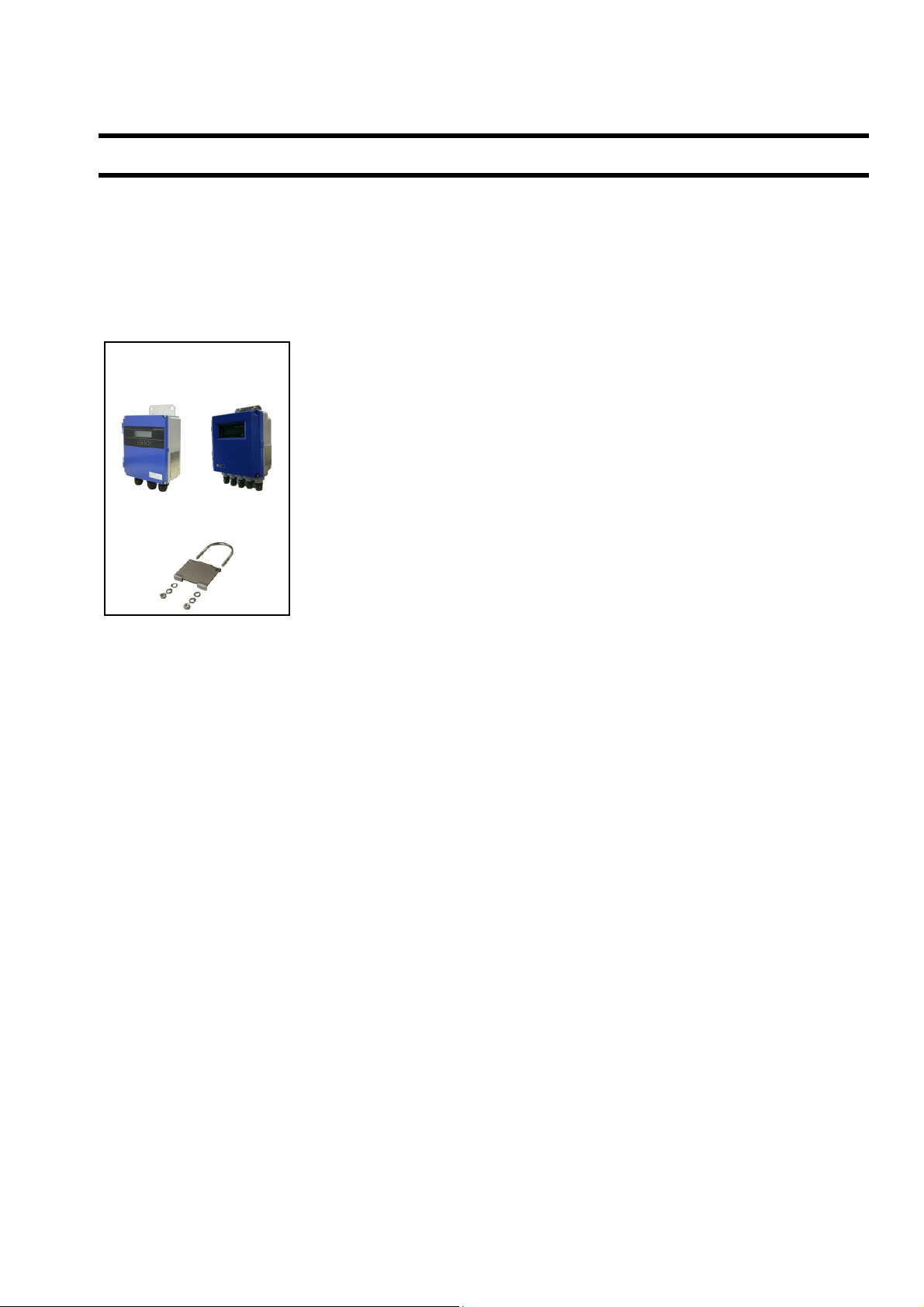
Flow transmitter (FSV)
Flow transmitter main unit ·································· 1 set
Waterproof gland (Built into the main unit) ············· 1 set
Wall mount frame (Built into the main unit) ············· 1 set
Panel mounting bracket (option)
(U bolt, support fixture, butterfly nut 2 pieces,
spring washer 2 pieces, plain washer 2 pieces) ······· 1 set
Flow transmitter (FSV)
FSV···S FSV···H
(IP66) (IP67)
CD-ROM (Instruction manual and loader software) ·· 1 piece
Out of delivery
Power cable
Output signal cable
RS-485 communication cable
Pipe mounting bracket
(option)
-1-
Page 10
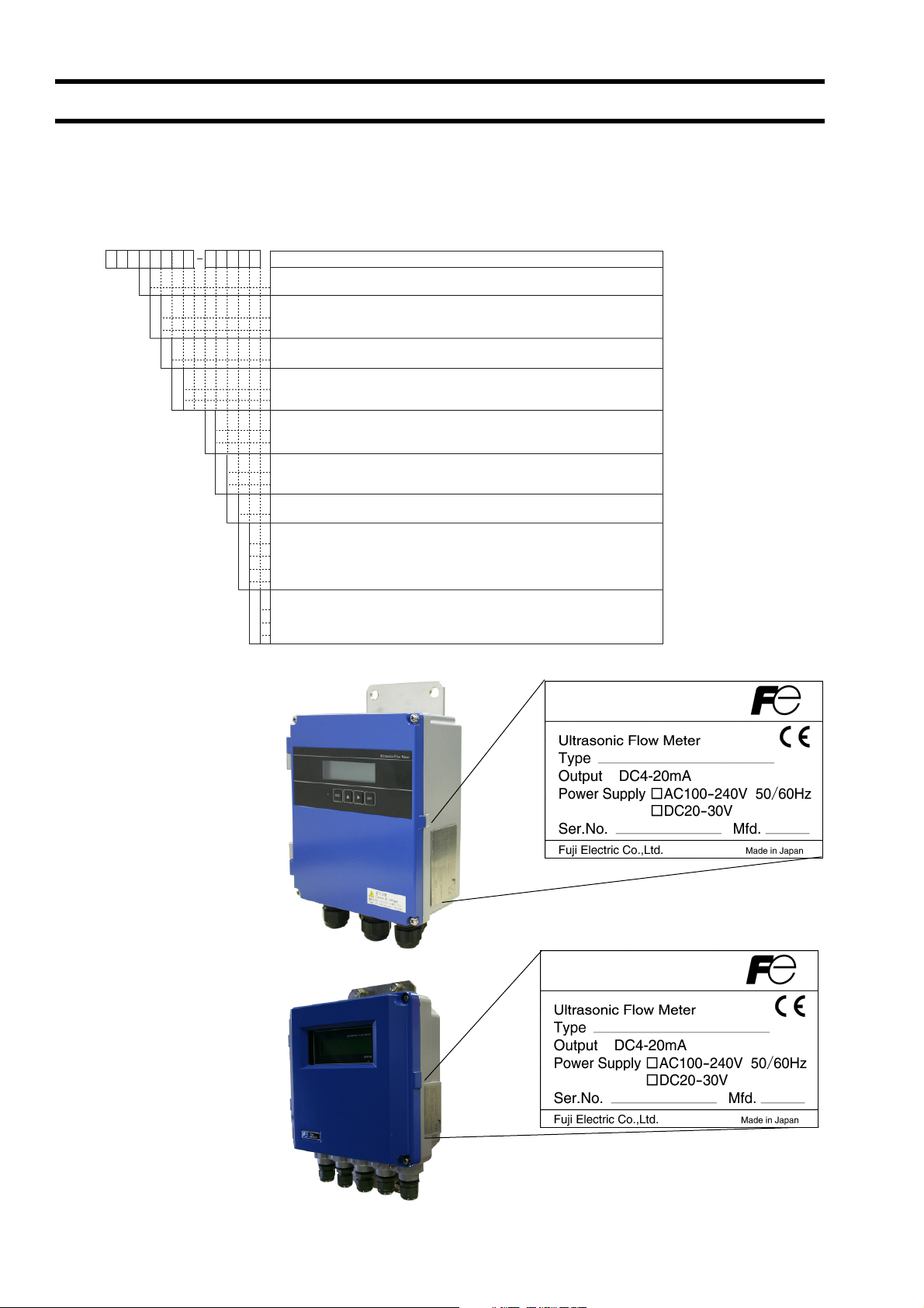
1.2. Check on type and specifications
The type and specifications of product are indicated on the specifications plate mounted on the flow transmitter and detector
frame.
Check that they represent the type you ordered, referring to the following code symbols.
<Flow transmitter (FSV)>
12345678 910111213
2YFSV Y
E
Y
D
Y
1
4
Flow transmitter : FSV···S (IP66)
Description
(Destination) (4th digit)
Standard (English)
(Communication) (5th digit)
None
RS485
(Use) (6th digit)
Single measuring path
(Power supply) (7th digit)
AC100 to 240V 50/60Hz
DC20 to 30V
S
H
Y
A
Y
(Case structure) (9th digit)
IP66
IP67
(Wire connection port) (10th digit)
Weatherproof gland provided [G1/2 and G3/8 (internal threads)]
Union (for pilica) with gland [G1/2 female screw] (when "H" is specified 9th digit)
(Combination with explosion-proof detector) (11th digit)
None
(Parameter setting) (12th digit)
None
Y
Setting provided
A
Setting provided + tag
B
Ta g
C
(Mounting method) (13th digit)
Pipe mount (if the 9th digit is S)
A
Wall mount
B
Pipe mount (if the 9th digit is H)
C
Flow transmitter : FSV···H (IP67)
-2-
Page 11
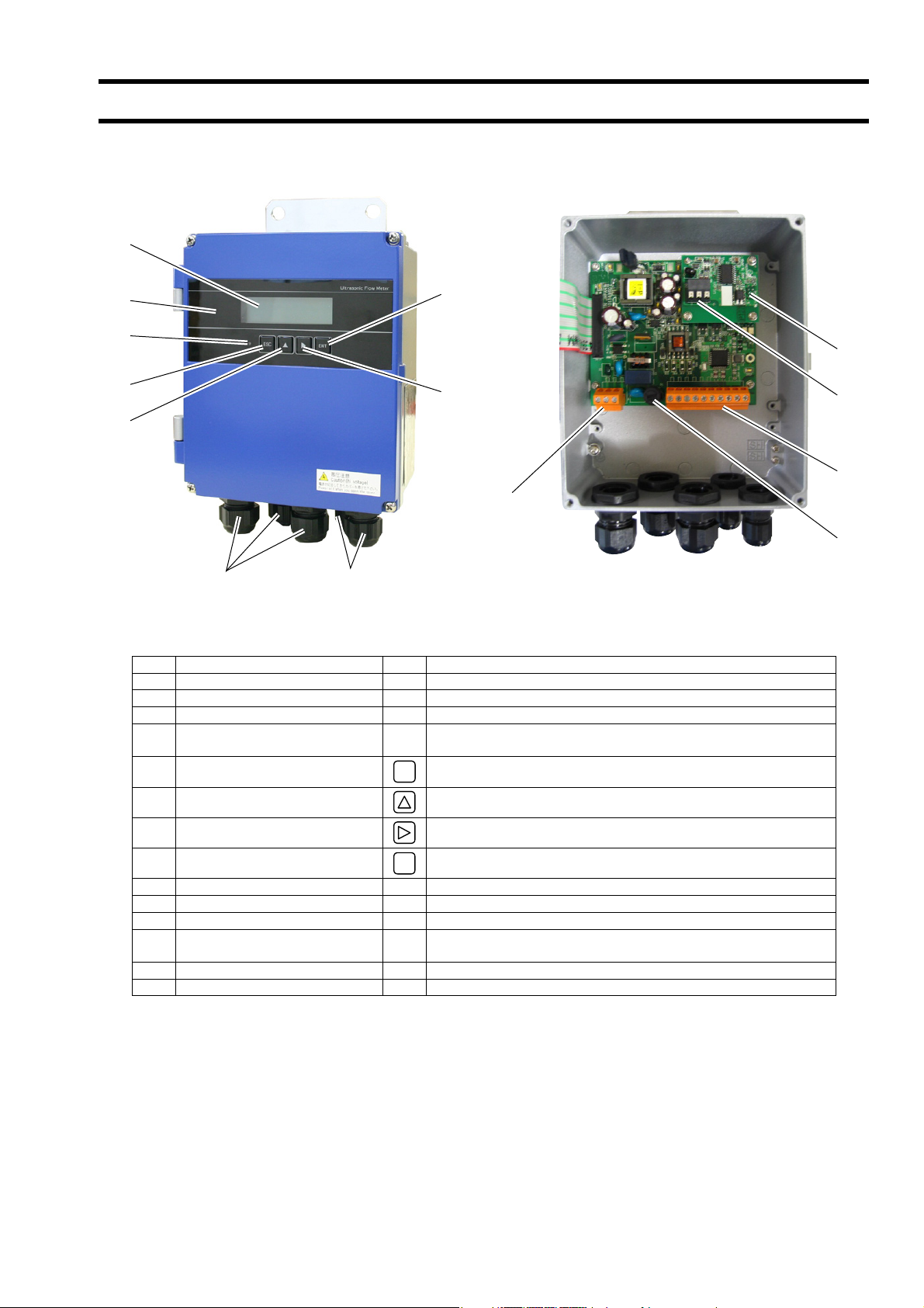
1.3. NAME AND FUNCTION OF EACH PART
1.3.1. Flow transmitter : FSV···S (IP66)
(9)
(3)
(4)
(5)
(6)
(1)
No. Name Key Description
(1) Wiring connection port, large Wiring connection port for power cable and output cable.
(2) Wiring connection port, small Wiring connection port for signal cable only.
(3) Indication and setting unit Indicates and sets the flow rate, etc.
Received wave diagnostic
(4)
indication (LED)
(5) Escape key
(2)
ESC
(8)
(7)
(10)
Indicates whether received wave is normal (green) or abnormal
(red).
Returns to the next-higher menu level or cancels the set status.
(14)
(12)
(11)
(13)
(6) UP key Selects items, numeric values and symbols.
(7) Shift key Moves the cursor and selects decimal place.
(8) Entry key
(9) LCD display Indicates the flow rate or setting.
(10) Power terminal Connects the power cable.
(11) Input/output terminal Connects signal cable, analog output or DO output cable.
(12) Communication board terminal
(13) Fuse holder Fuse holder
(14) Communication board Mounted if communication is optionally designated.
ENT
Enters a selection or registers a setting.
Connects communication cable.
(A communication board is optional)
-3-
Page 12
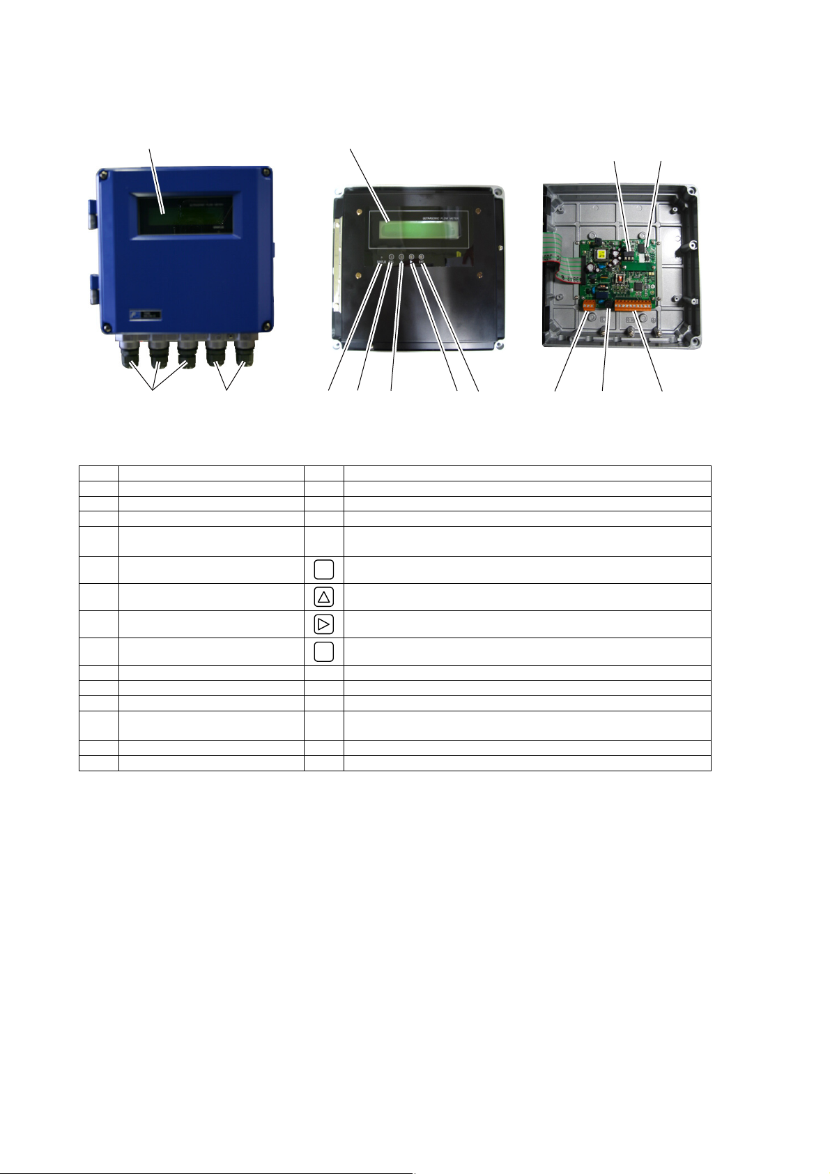
1.3.2. Flow transmitter : FSV···H (IP67)
(9)
(3)
(12)
(14)
(1)
No. Name Key Description
(1) Wiring connection port Wiring connection port for power cable and output cable.
(2) Wiring connection port Wiring connection port for signal cable only.
(3) Indication and setting unit Indicates and sets the flow rate, etc.
Received wave diagnostic
(4)
indication (LED)
(5) Escape key
(6) UP key
(7) Shift key
(8) Entry key
(9) LCD display Indicates the flow rate or setting.
(10) Power terminal Connects the power cable.
(11) Input/output terminal Connects signal cable, analog output or DO output cable.
(12) Communication board terminal
(13) Fuse holder Fuse holder
(14) Communication board Mounted if communication is optionally designated.
(2) (4) (5) (6) (7) (8) (10) (13) (11)
Indicates whether received wave is normal (green) or abnormal
(red).
ESC
Returns to the next-higher menu level or cancels the set status.
Selects items, numeric values and symbols.
Moves the cursor and selects decimal place.
ENT
Enters a selection or registers a setting.
Connects communication cable.
(A communication board is optional)
-4-
Page 13
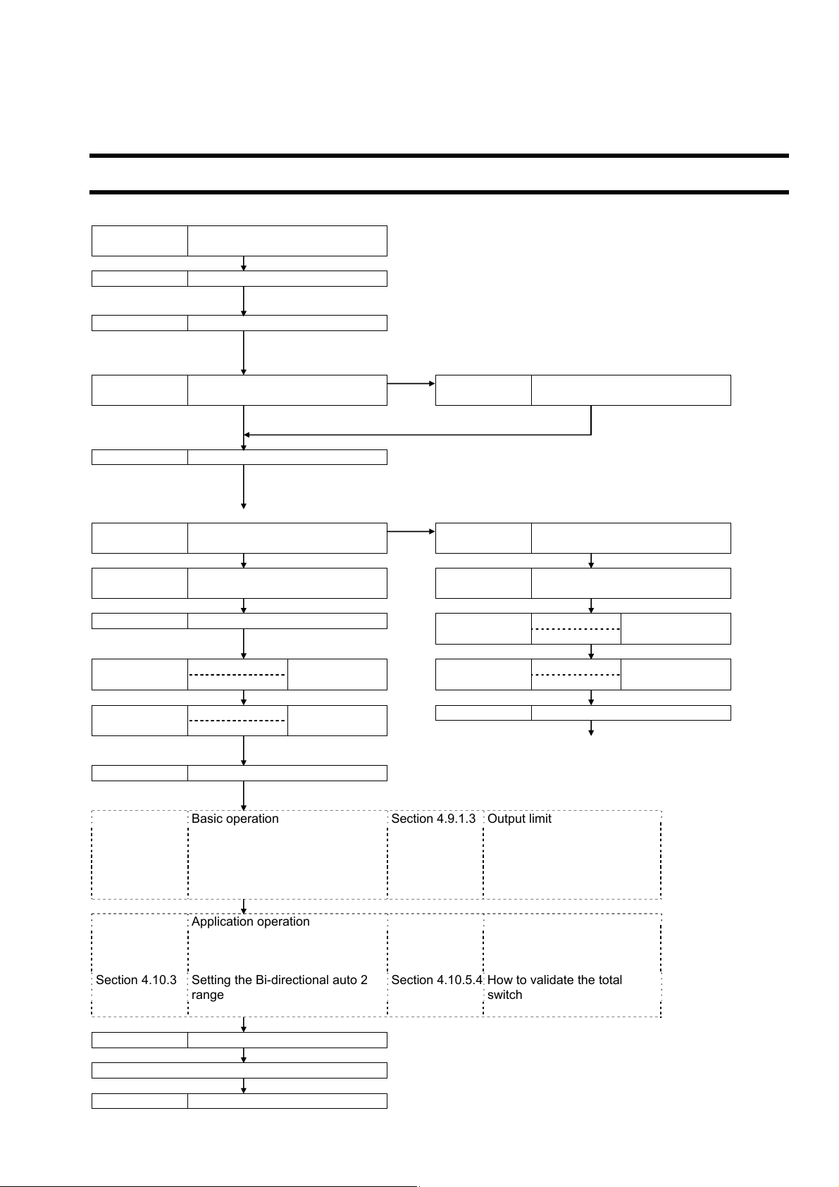
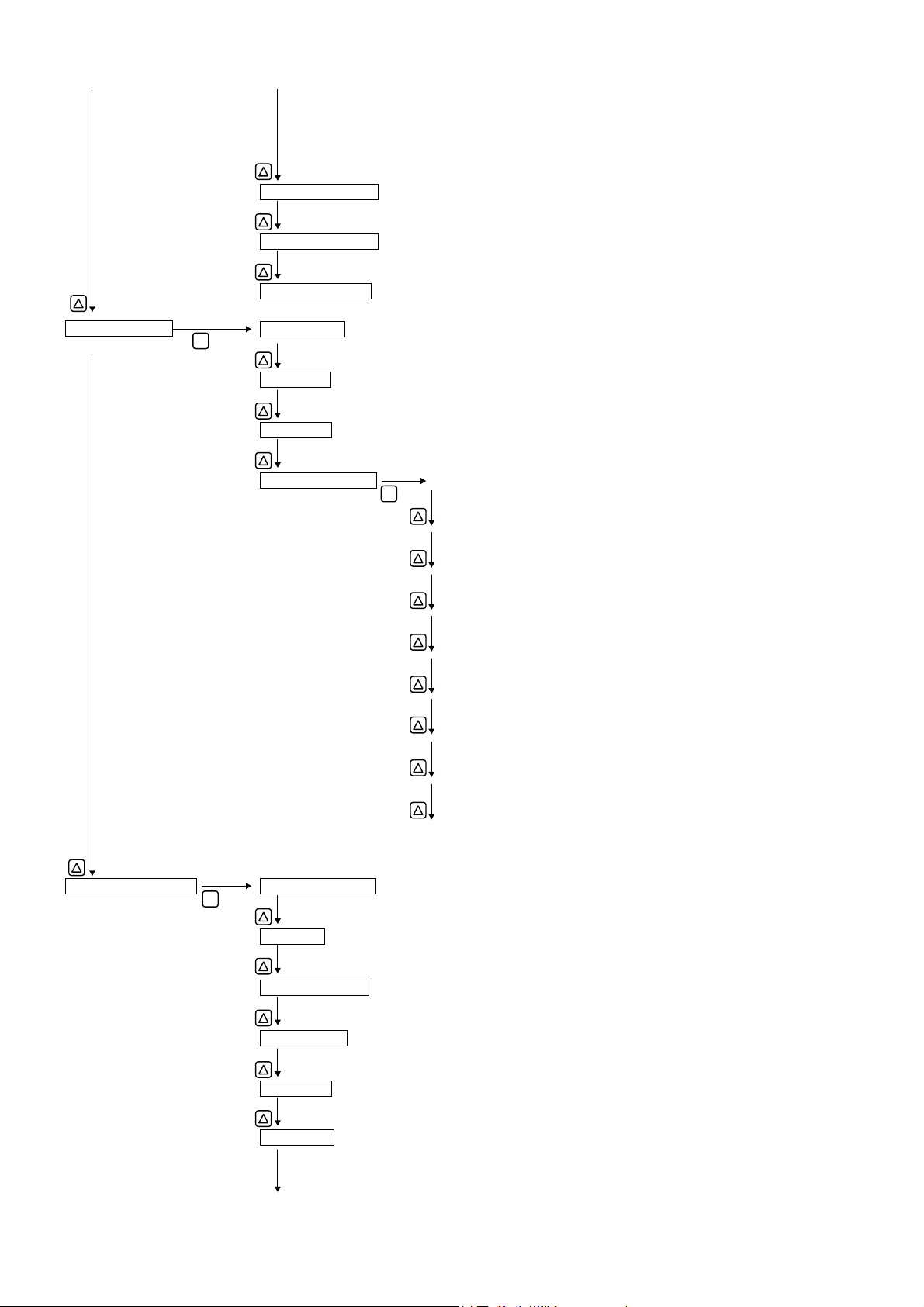
2. INSTALLATION AND BEFORE START OF OPERATION OF THE FLOW TRANSMITTER
2.1. Outline of installation procedure
Install the flowmeter according to the following procedure.
Section 3.2
Section 3.3
Power ON * Check the power supply specifications and wiring before
Section 4.4 Parameter protection * Metric system is selected for unit.
* The initial display language is English. Switch the languages
NG When Y or C is selected for the 12th digit
Section 4.6
OK When A or B is selected for the
Section 5 Mounting of detector * Be careful not to mount the sensor units with wrong mounting
NG (LED display is red)
Section 6.5.1.3 Checking the RAS information
OK (LED display is green)
Section 6.5.2
Check the data display AGC U
AGC D
AGC U
AGC D P/H D
P/H U
P/H D
Contact Fuji Electric’s service representative.
Section 4.7 Zero Adjustment *
Basic operation Section 4.9.1.3 Output limit * Check A, B for
Section 4.8 Setting of unit Section 4.9.2 Setting thee
Section 4.9.1.1 Setting of flow rate range (single
Section 4.9.1.2 Setting of analog output at error
Application operation
Section 4.9.1 Setting of flow rate range Section 4.10.5.2 How to validate the alarm
Section 4.10.1 Setting automatic 2 ranges
Section 4.10.2 Setting the Bi-directional range Section 4.10.5.3 Setting the flow switch
Section 4.10.3 Setting the Bi-directional auto 2
Section 7.3 ORDERING INFORMATION
Section 6 CHECK AND MAINTENANCE
Note) Set the parameter protection to OFF before you change settings or perform zero adjustment.
Installation of flow transmitter
Flow transmitter wiring
Checking and Setting of Piping
Specifications/Detector
12th digit
Displaying the data in
maintenance mode
45% or more
5528 to 6758
range)
(Burnout)
range
Run (Measurement)
turning on the power. (Refer to “1.2.Check on type and
specifications”.)
as required.
P/H U
Section 6.5.6 Checking received waveforms
Section 4.9.3 Setting the DO output
Section 4.9.3.1 How to validate the total pulse
Section 4.9.4 Setting the LCD indication
Section 4.10.5.4 How to validate the total
Section 4.6.2 Piping parameter setting method
dimension. Mount it with the dimension displayed at the
process setting of the piping parameter. (Refer to “5.
Mounting of detector”.)
Section 6.5.2
Before performing zero point adjustment, check that the pipe
is filled with fluid, the fluid is in still state, and that the
measurement status is normal.
output
output
switch
Displaying the data in
maintenance mode
Check the data display
45% or more
Outside the range
of 5528 to 6758
the 12th digit of
code symbol
only.
-5-
Page 14
3. INSTALLATION
Select an installation location that satisfies the following conditions for ease of maintenance and inspection, service life of
the instrument, and assurance of reliability all considered.
CAUTION
(1) A place where ambient temperature and humidity are -20 to +55°C and 95% RH or less for flow transmitter
(FSV)
(2) A place not exposed to direct sunshine nor inclement weather.
(3) Space for periodic inspection and wiring work is available.
(4) A place not subjected to radiated heat from a heating furnace, etc.
(5) A place not subjected to corrosive atmosphere.
(6) A place not to be submerged.
(7) A place free from excessive vibration, dust, dirt and moisture.
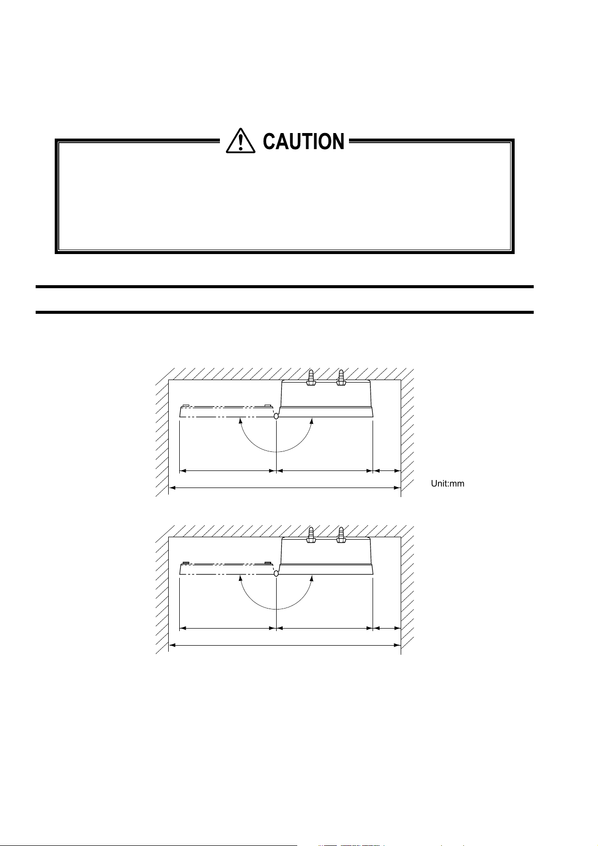
3.1. Installation location of flow transmitter
Secure at least 100 mm of space between the flow transmitter and nearby wall. Also secure a space of opening the front
cover in case of maintenance.
Allow space for cable wiring under the case.
N
E
P
O
O
P
E
147
N
240
147
400 or more
Fig. 3.1 Top view of mounting (Flow transmitter : FSV···S (IP66))
240
100 or
more
100 or
more
Unit:mm
580 or more
Fig. 3.2 Top view of mounting (Flow transmitter : FSV···H (IP67))
-6-
Unit:mm
Page 15
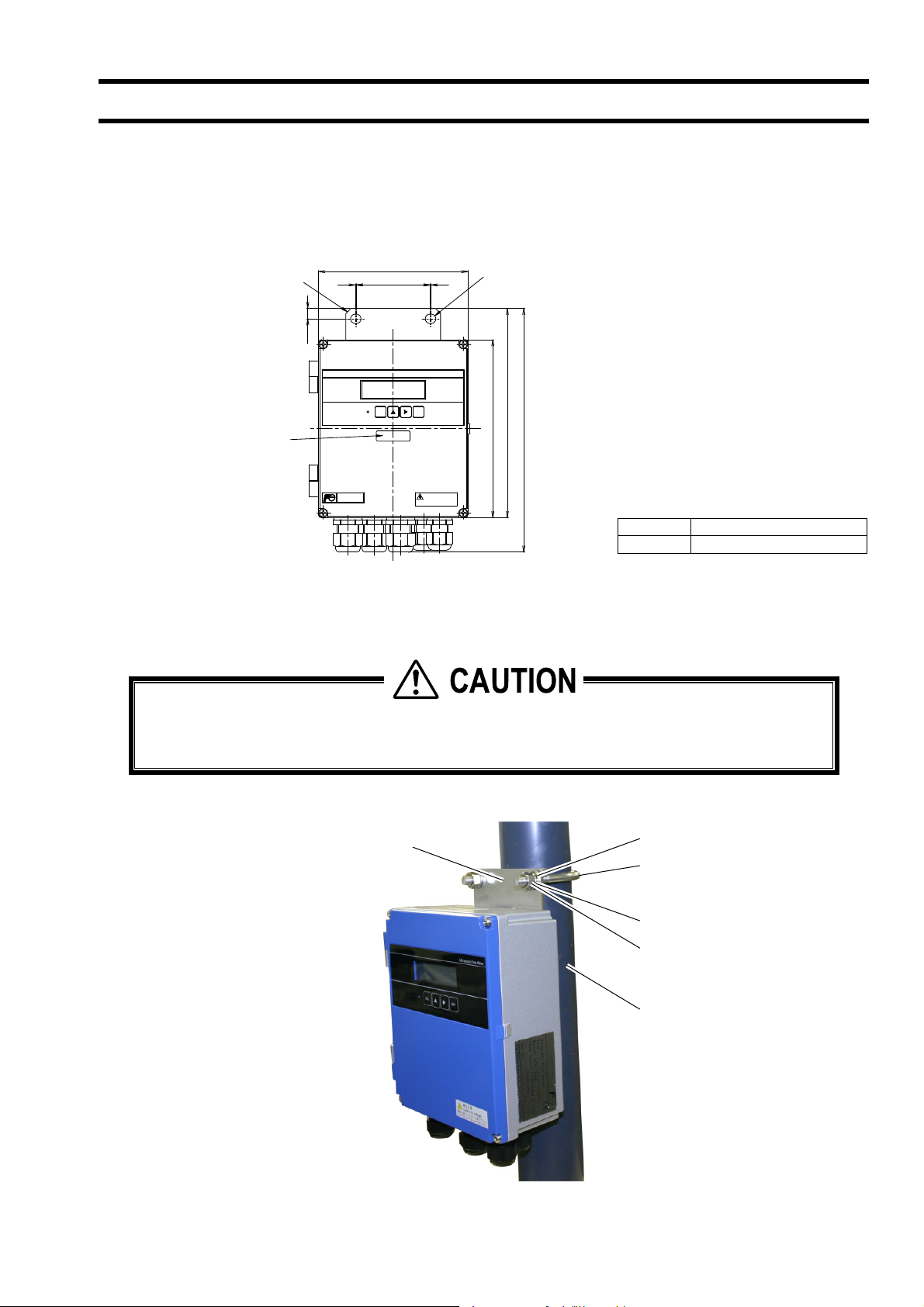
3.2. Installation of flow transmitter
The flow transmitter may be mounted on a wall or 2B pipe stand (option).
3.2.1. Wall mounting (Flow transmitter : FSV···S (IP66))
For wall mounting, use two M8 bolts.
Drill holes according to the mounting hole dimensions shown below, and fasten the flow transmitter using the M8 bolts.
Mounting plate
Stainless tag
(option)
1
10
ESC
142
70
ENT
1
Ultrasonic Flow Meter
Mounting hole 9 × 10
200
170
(233)
TIME
DELTA-C
高圧注意
Caution(hi voltage)
電源を切断してからカバーを開けて下さい。
Power off when you open the cover.
Norminal Standard tightening torque
M8
12.5 [Nm]
3.2.2. 2B pipe stand mounting (Flow transmitter : FSV···S (IP66))
CAUTION
When mounting on 2B pipe, be sure to use a complete set of fixtures (U bolt, support fixture, plain washer,
spring washer, nut) furnished if optionally designated. Tighten the nut by hand. If any support fixture is not used
or if the assembly is excessively tightened by tool, the wall mounting fixture may be deformed.
Mount the instrument on 2B pipe stand as illustrated below.
Support fixture
Plain washer
U bolt (M8)
Spring washer
-7-
Nut
2B pipe stand
Page 16
r
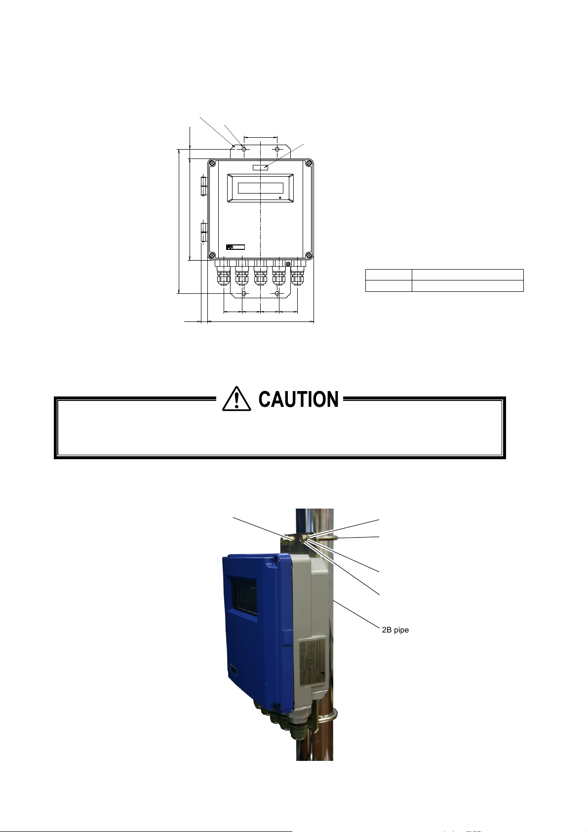
3.2.3. Wall mounting (Flow transmitter : FSV···H (IP67))
For wall mounting, use four M8 bolts.
Drill holes according to the mounting hole dimensions shown below, and fasten the flow transmitter using the M8 bolts.
Mounting plate
Mounting hole 2-φ9
20
72
Stainless tag
(option)
ULTRASONICFLOWMETER
STATUS
312
220
TIME
DELTA‑C
Norminal Standard tightening torque
12.5 [Nm]
14
40
230
40
M8
4040
3.2.4. 2B pipe stand mounting (Flow transmitter : FSV···H (IP67))
CAUTION
When mounting on 2B pipe, be sure to use a complete set of fixtures (U bolt, support fixture, plain washer,
spring washer, nut) furnished if optionally designated. Tighten the nut by hand. If any support fixture is not used
or if the assembly is excessively tightened by tool, the wall mounting fixture may be deformed.
Mount the instrument on 2B pipe stand as illustrated below.
Support fixture
Plain washer
-8-
U bolt (M8)
Spring washe
Nut
2B pipe stand
Page 17
3.3. Flow transmitter wiring
3.3.1. Cautions in wiring
(1) Use a special coaxial cable (FLYC) as a signal cable between the detector and flow transmitter (FSV). Do
not provide a junction or splice of the signal cable midway.
(2) The signal cable between the detector or flow transmitter should be run in metallic conduits. Upstream and
downstream signal cables may be put in the same conduit but, to avoid interference, do not put the power
cable together.
(3) For output signal, use a shielded cable, where possible.
(4) To avoid noise interference, do not put the cables together with heavy duty line or the like into the same
duct.
(5) If a ground wire is included in the power cable, connect it to ground as it is.
(6) A power switch is not provided on the instrument and must be mounted separately.
(7) Seal unused wiring ports by furnished caps.
CAUTION
3.3.2. Applicable wires
Use the following cables.
Power cable : 3-wire or 2-wire cabtyre cable (Allowable temperature: 65°C or more)
Nominal sectional area 0.75mm2 or more
Outside diameter Ф11 m m
Output signal cable : 2-wire or multi-wire cabtyre cable as required (Allowable temperature: 65°C or more)
Outside diameter Ф11 m m
Detector-flow transmitter cable : Signal cable by type designation
In case of detector FSSA : High-frequency coaxial double shield cable with
FSSC characteristic impedance of 50Ω
FSSD With one-side waterproof BNC connector
FSSH Outside diameter Ф7.3mm
In case of detector FSSE High-frequency coaxial double shield cable with
characteristic impedance of 50Ω
Outside diameter Ф7.3mm
3.3.3. Treatment of wiring port
The casing of the flow transmitter is IP66 and IP67. However, if installed in a humid place, the wiring ports must be made
airtight to avoid ingress of moisture, condensation, etc. Be sure to use the waterproof glands furnished with the instrument
in order to ensure the waterproof means. A gland, which is not ready to be used, should be sealed by supplied cover.
CAUTION
Do not install the instrument where there is a risk of flooding.
-9-
Page 18
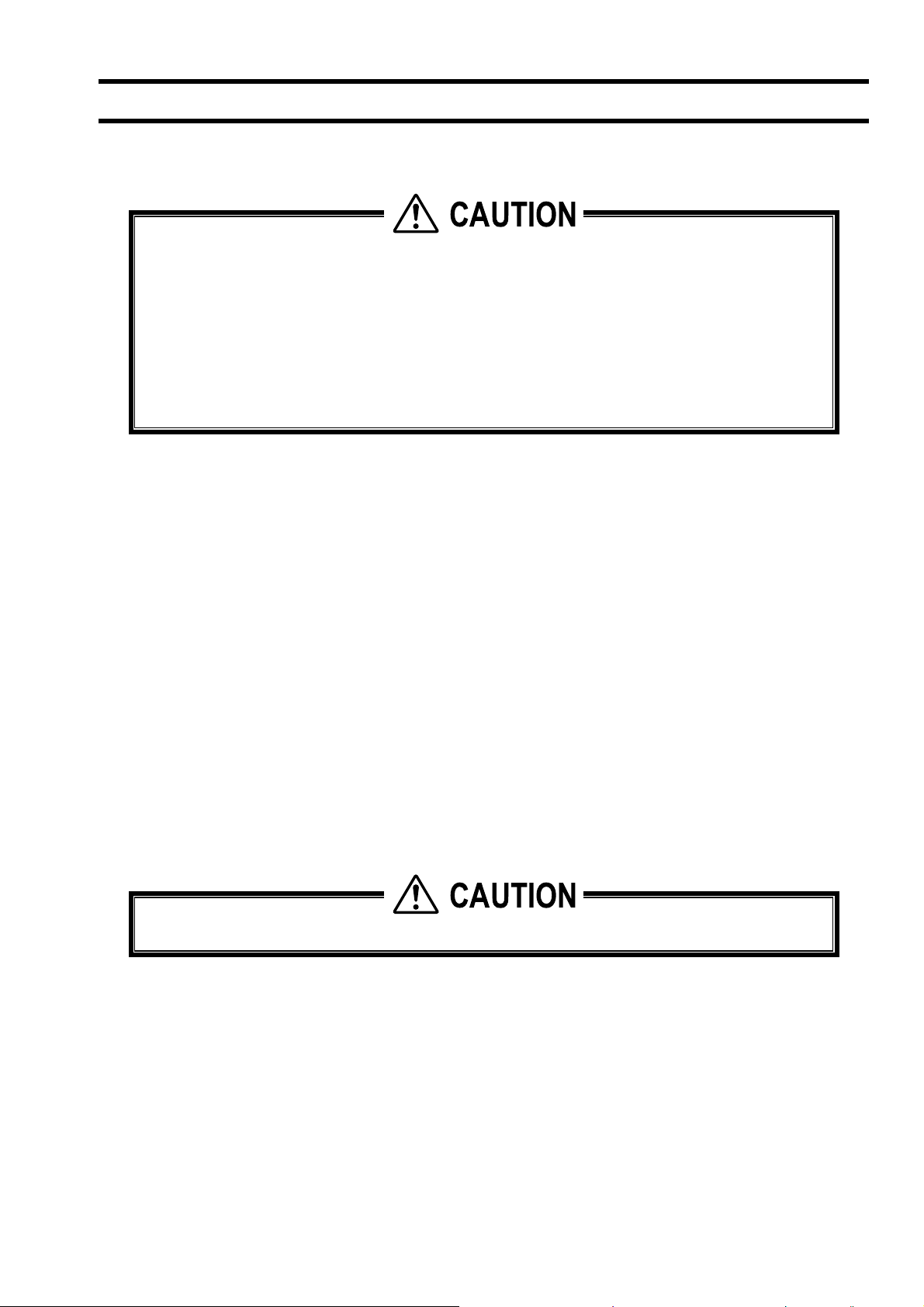
3.3.4. Wiring to each terminal
3.3.4.1. Flow transmitter : FSV···S (IP66)
Carry out wiring to each terminal according to the following figure.
Power supply board terminal block
Power cable
Output signal cable
(analog output, DO1,
DO2, Communication)
Upstream
sensor cable
Downstream
sensor cable
Main board terminal block
AC power supply
100 to 120V AC
or 200 to 240V AC
50/60Hz
123
L N FG
DC power supply
20 to 30V DC
123
+
-
Communication board terminal
block (option)
RS-485
123
SG A-B
+
+
-
FG
External ground terminal
Ground terminal (M4)
123456 7 8 910
--
+
+
DO1 DO2
TROUT
DC30V, 50mA
Black
White
-
+
I out
To upstream
sensor
GND
HF1 HF2
TO SENSOR
To downstream
sensor
GND
SHSH
DOWN STRUP STR
White
Black
Yellow
Iout : Analog output
DO1, 2 : Transistor/open
collector
Note 1) Terminal block is insertion type to connect a cable. Use bar terminal as crimp-style terminals.
Note 2) Be sure to connect ground terminal to external ground terminal. (Class D grounding)
Note 3) For output signal, use multiple core cable as required.
Note 4) Differential signal line of RS-485 consists of two pins.
means B+, and means A-.
-10-
Page 19
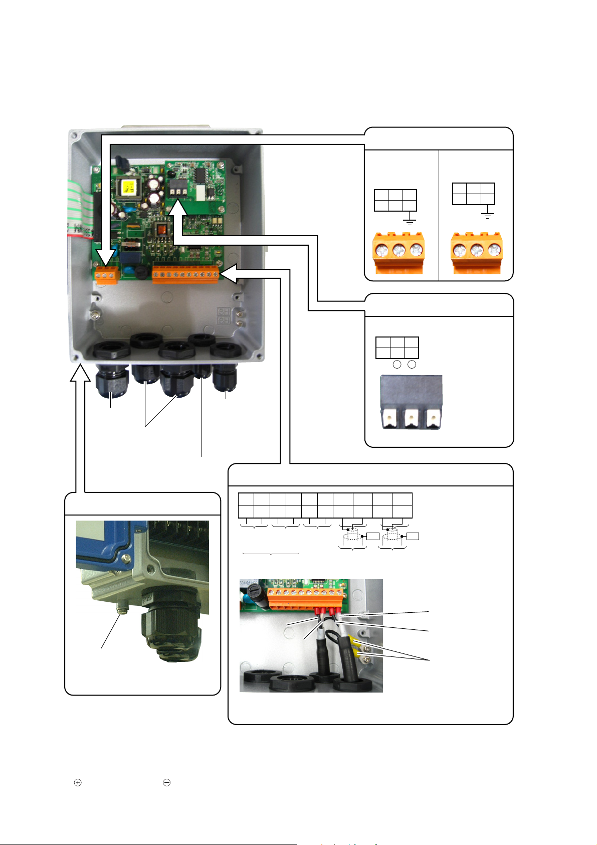
3.3.4.2. Flow transmitter : FSV···H (IP67)
Carry out wiring to each terminal according to the following figure.
Communication board terminal
block (option)
RS-485
123
SG A-B
+
-
+
Power cable
Output signal cable
(analog output, DO1,
DO2, Communication)
Downstream
sensor cable
Power supply board terminal block
AC power supply
100 to 120V AC
or 200 to 240V AC
50/60Hz
DC power supply
20 to 30V DC
123
L N FG
123
+
-
FG
sensor cable
External
ground terminal
(M4)
Upstream
Main board terminal block
123456 7 8 910
--
+
+
DO1 DO2
TROUT
DC30V, 50mA
Black
White
+
I out
-
GND
GND
HF1 HF2
DOWN STRUP STR
TO SENSOR
SHSH
Black
White
Iout : Analog output
DO1, 2 : Transistor/open
collector
Yellow
To upstream
sensor
To downstream
sensor
Note 1) Terminal block is insertion type to connect a cable. Use bar terminal as crimp-style terminals.
Note 2) Be sure to connect ground terminal to external ground terminal. (Class D grounding)
Note 3) For output signal, use multiple core cable as required.
Note 4) Differential signal line of RS-485 consists of two pins.
means B+, and means A-.
-11-
Page 20
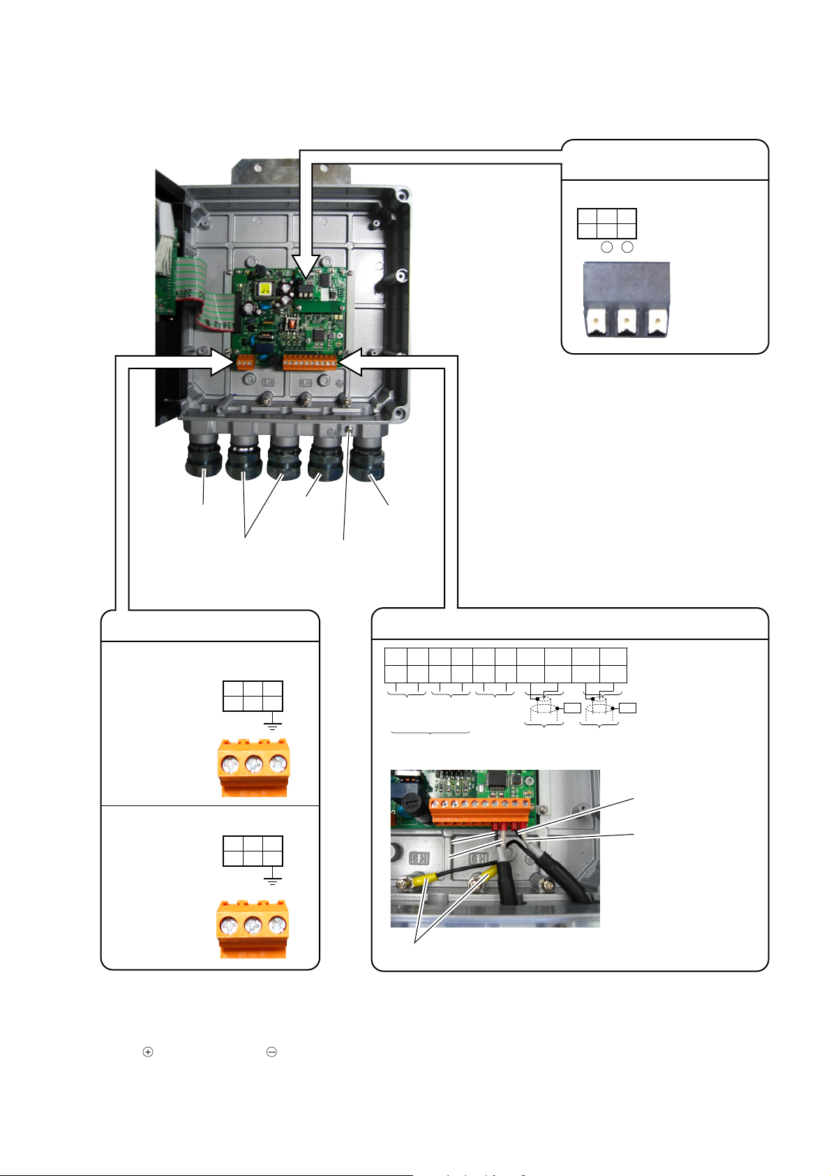
3.3.5. How to connect to terminal block.
3.3.5.1. Cable treatment
The cable connecting to the terminal block is available to connect with bare wire but for safety’s sake please crimp the bar
terminal to connect.
When you cut and use the signal cable, make sure to cut the cable in same length of upstream and downstream.
Note) if cable lengths are different, it may adversely affect the output.
Usable wiring materials
• Wire
Gauge: AWG20 (0.5mm
Strip-off length: 8 to 10mm
2
) to AWG16 (1.5mm2)
• Bar terminal
Weidmuller
www.weidmuller.com
AWG20
to
AWG16
øD1
8 to 10mm
10
16
Wire size (mm2) AWG øD1 (mm) øD2 (mm) Type
0.5 20 1 2.6 H0.5/16
0.75 18 1.2 2.8 H0.75/16
1 17 1.4 3 H1/16
1.5 16 1.7 3.5 H1.5/16
Note1) Make sure to use PZ6/5(H0.25 to H6 for sleeve) as a crimp tool for caulking.
Note2) Applicable sleeve is required for electric wire.
Note3) Insert the electric wire to the end of H sleeve so as to crimp.
Note4) Length of stripped wire is 12mm.
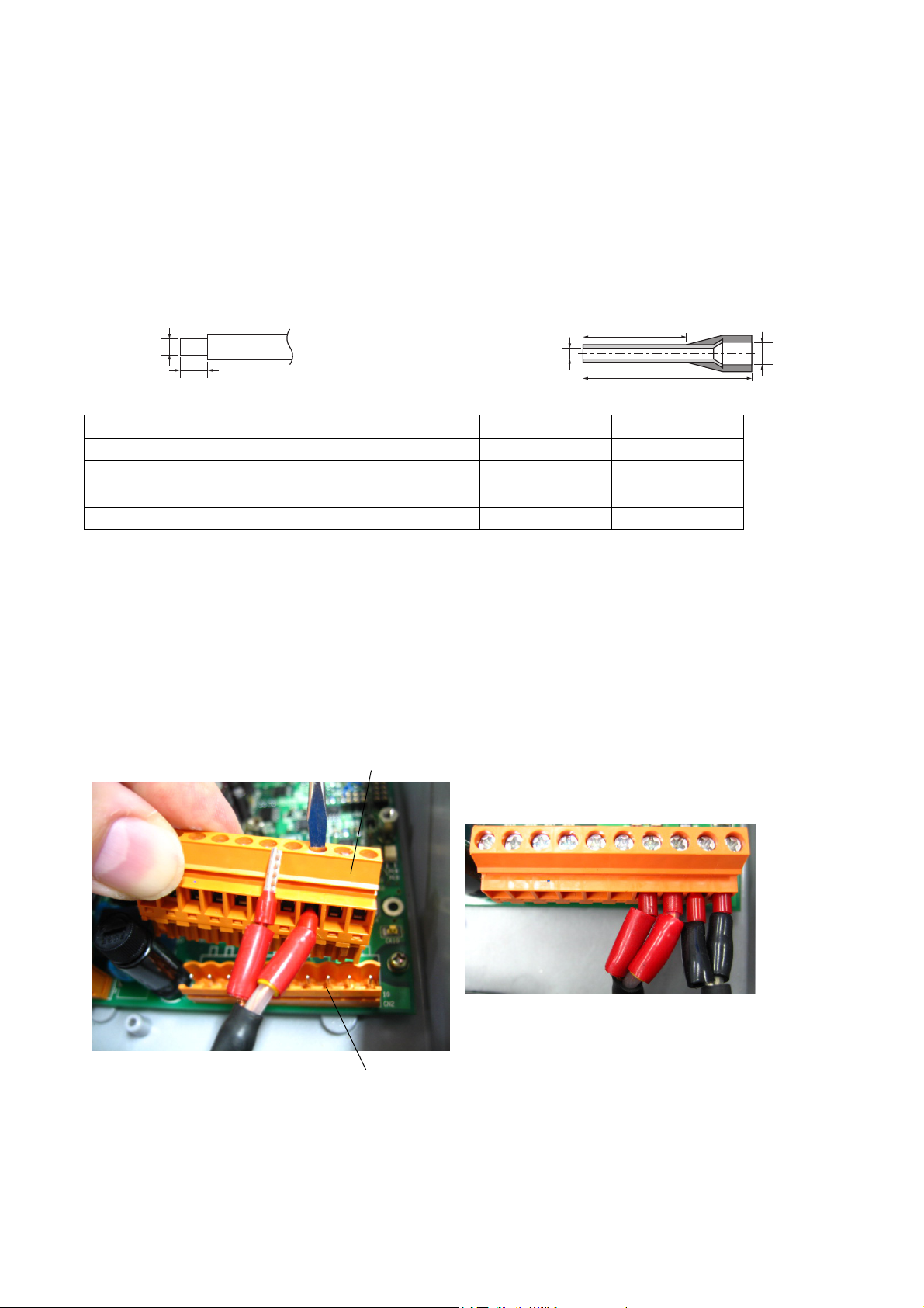
3.3.5.2. How to connect to power supply/terminal block for signal.
Please prepare the flathead screwdriver (head size: 0.6 x 3.5mm) so as to tighten the cable.
(1) Pull off the cable socket side from the plug on the substrate with holding the right side of the socket by hand.
(2) If cable connector is closed, turn the screw to the left on the top to open.
(3) Insert the cable and turn the screw to the right on the top to fix.
(4) Install the cable socket side to the plug on the substrate.
Cable socket side
øD2
Note) Make sure to conduct the procedure not to damage the printed-circuit board when you remove and install the cable
socket side.
Plug on substrate
-12-
Page 21

3.3.5.3. How to connect to communication terminal block.
Please prepare the flathead screwdriver (head size: 0.6 x 3.5mm) so as to connect the cable.
1. Push the clamp so as to open the connector.
2. Insert the cable to the connector and release the clamp to fix the cable.
Clamp
-13-
Page 22
4. Parameter
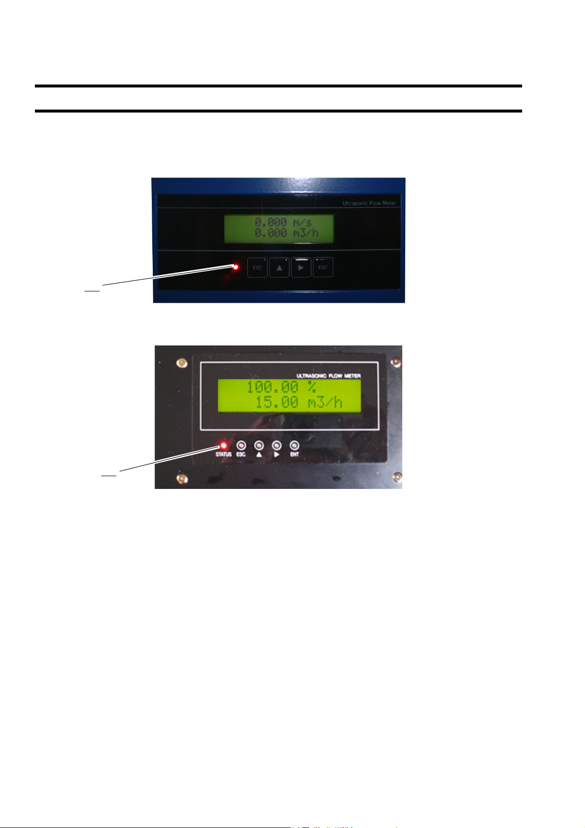
4.1. Description of display/setting unit
Display unit and setting unit are as shown below.
4.1.1. Flow transmitter : FSV···S (IP66) display/setting unit
LED
4.1.2. Flow transmitter : FSV···H (IP67) display/setting unit
LED
-14-
Page 23
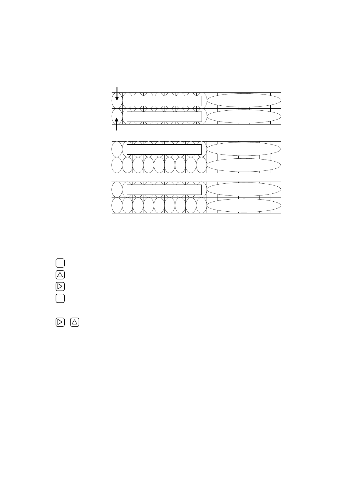
4.1.3. Description of display/setting unit
○ LCD display: Displays the measurement and setting (indication in 16 digits, 2 line).
“Measurement display”
Up to 8 digits including the decimal point are displayed in the data field. When the displayed
digits exceed, “<” is displayed at the first digit. When the range exceeds maximum or is below
minimum setting, “OVERFLOW” or “UNDERFLOW” is displayed blinking on the Display 2.
Flow direction, during test mode “T”
Display 1
Display 2
Flow direction
Display 1
Display 2
Display 1
Display 2
○ LED display: Indicates whether the received wave is normal or not.
Set the parameter by setting switches.
ESC
ESCAPE key : Return to the next-higher menu level or cancels the set status.
O
U D
(Green) : Received wave is normal.
(Red) : Received wave is abnormal.
Data
Data
Data Unit
V E R L O WF
Data Unit
N E R L O WF
Unit
Unit
UP key : Selects items, numeric values and symbols.
SHIFT key : Moves the cursor and selects decimal place.
ENT
ENTRY key : Enters a selection or registers a setting.
Note) For changing the parameter, enter the changed value, and press this key to confirm
that it is registered.
Uses DOWN key for selecting the items, values and codes.
+
DOWN key : DOWN key function is conducted by holding down SHIFT key and press DOWN key.
-15-
Page 24
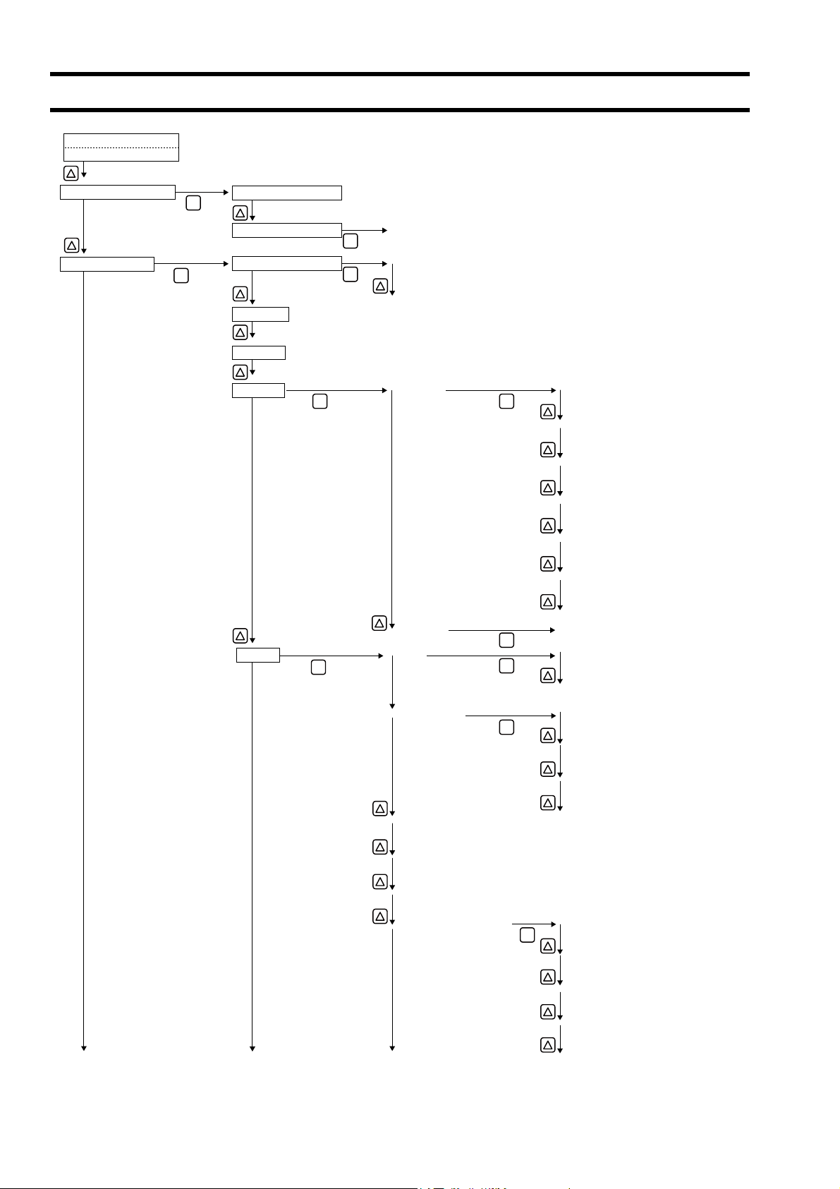
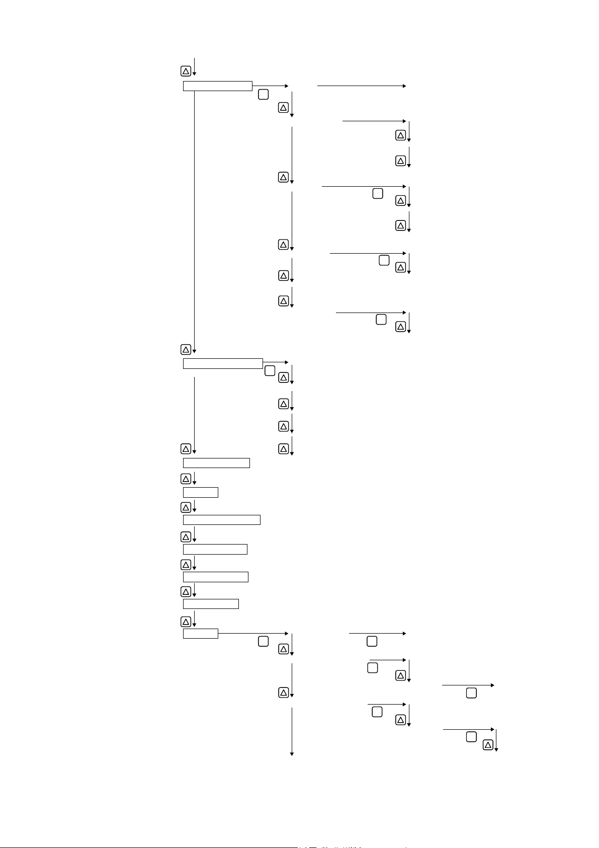
4.2. Composition of key operation
0.000 m/s
0.000 m3/h
Measurement mode
PAR.PROTECTIO PROTECTION ON
ENT
ENT
PROTECTION OFF
DAMPING
CUT OFF
ENT
RANGE
ENT
ENT
ENT
INPUT ID.NO
CLEARZERO ADJUSTMENTOUTPUT SET UP
SET ZERO
KIND
ENT
ENT
ENT
VELOCITY1ST ROWDISPLAY
FLOW RATE
FLOW RATE(%)
+TOTAL(ACTUAL)
+TOTAL PULSE
-TOTAL(ACTUAL)
-TOTAL PULSE
(Same as "1ST")2ND ROW
VELOCITY
FLOW RATE
ENT
SINGLERANGE TYPE
AUTO 2
BI-DIR
FULL SCALE 1
BI-DIR AUTO 2
FULL SCALE 2
RANGE HYS.
BURNOUT (CURRENT) NOT USED
ENT
HOLD
UPPER
LOWER
ZERO
-16-
Page 25
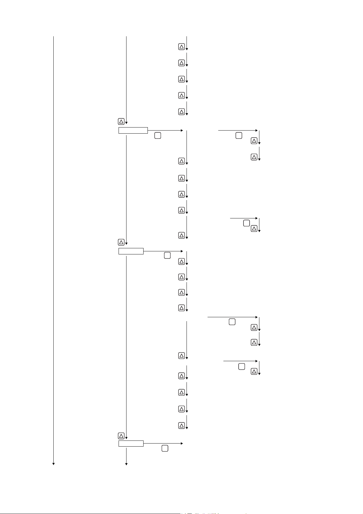
BURNOUT TIMER
OUTPUT LIMIT LOW
OUTPUT LIM.HIGH
RATE LIMIT
RATE LIMIT TIMER
ENT EN T
TOTAL RATE
TOTAL PRESET
PULSE WIDTH
BURNOUT (TOTAL) HOLD
BURNOUT TIMER
ENT
NOT USEDDO1 OUT
+TOTAL PULSE
-TOTAL PULSE
FULL SCALE 2
STARTTOTAL MODETOTAL UNIT
STOP
TOTAL RESET
ENT
NOT USED
ENT
ENT
LLAMRALA
HARDWARE FAULT
PROCESS ERROR
FLOW SWITCH FLOW SW HIGH
ENT
FLOW SW LOW
TOTAL SWITCH
AO RANGE OVER
PULSE RANGE OVER
-FLOW DIRECTION
(Same as "DO1 OUT")DO2 OUT
-17-
Page 26
CALIBRATION ZERO
CALIBRATION SPAN
OPERATION MODE
MEASURE SETUP
ENT
SYSTEM UNIT
FLOW UNIT
TOTAL UNIT
PROCESS SETTING OUTER DIAMETER
ENT
PIPE MATERIAL
WALL THICKNESS
LINING MATERIAL
LINING THICKNESS (Except for "NO LINING")
KIND OF FLUID
VISCOSITY
SENSOR MOUNT
MAINTENANCE MODE RAS INFORMATION
ENT
CURRENT
OUTPUT SETTING
TOTAL PULSE
DO CHECK
TEST MODE
SENSOR TYPE
-18-
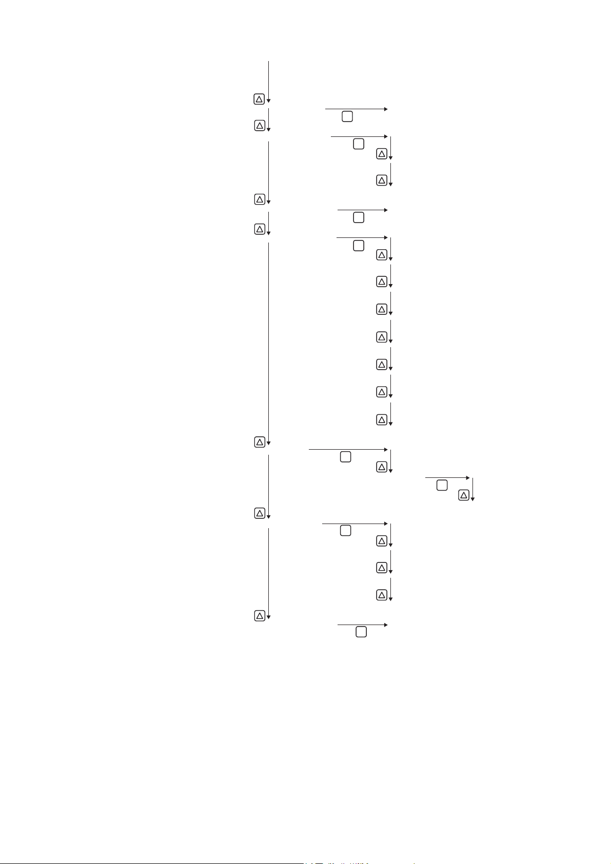
Page 27
SYSTEM LANGUAGE
ENT
MODECOMMUNICATION RS-485
BOUAD RATE 9600bps
ENT
STOP BIT
STATION No.
ENT
ENGLISH
ENT
ENT
19200bps
38400bps
NONEPARITY
ODD
EVEN
1 BIT
2 BITS
MODBUSPROTOCOL
M-Flow
REGISTER ID NO.
VER. NO.
MEMORY INITIALIZE
*
LCD BACKLIGHT
LCD/LED CHECK
DATA DISPLAY
*
ENT
JAPANESE
GERMAN
FRENCH
SPANISH
* Only for service technician
ENT
TRIGGER CONTROL
ENT
128 (Initial value)TRANS.COUNTDETAILS
AUTO (Initial value)
WINDOW CONTROL
-19-
ENT
MANUAL
ENT
AUTO (Initial value)
MANUAL
ENT
TRIGGER LEVEL
U:OPEN TIME
D:OPEN TIME
Page 28
SATURATION
MEAS.METHOD
SIGNAL BALANCE
TRANS.PATTERN
ENT
ENT
ENT
ENT
128 (Initial value)
METHOD 1
METHOD 2 (Initial value)
METHOD 3
25% (Initial value)
BURST 1
BURST 2
BURST 3 (Initial value)
BURST 4
BURST 5
CHIRP 4
CHIRP 8
SIGNAL PEEK
TRANS.WAIT TIME
ENT
ENT
ENT
RESERVE
AUTO (Initial value)AGC GAIN
MANUAL
ENT
U: AGC
D: AGC
0.125V (1024)
0.25V (2048)
0.375V (3072) (Initial value)
0.5V (4096)
5msec (Initial value)
-20-
Page 29

4.3. Parameter initial value list
Factory-set value is shown below. (When parameter setting is not provided.)
Setting unit Setting range Initial value Setting value
1 Parameter protection No. of menu: 2 PROTECTION ON PROTECTION ON, PROTECTION OFF
2 ID No 0000 to 9999 0000 ID No. is invalid when 0000 is selected.
3 Language No. of menu: 5 English *1 English, Japanese, German, French and
4
5 Flow unit No. of menu: 18 m3/h L/s, L/min, L/h, L/d, kL/d, ML/d, m3/s, m3/min,
6 Total unit No. of menu: 8 m3 mL, L, m3, km3, Mm3, mBBL, BBL, kBBL
7 Outer diameter 6.00 to 6200.00mm 60.00mm [mm, in]
8 Pipe material No. of menu: 13
9 Wall thickness 0.10 to 100.00mm 4.00mm [mm, in]
10 Lining material No. of menu: 8
11 Lining thickness 0.01 to 100.00mm – [mm, in]
12 Kind of fluid No. of menu: 18
13 Dynamic viscosity
14 Sensor mounting method No. of menu: 2 V method V method, Z method
15 Sensor type No. of menu: 10 FSSA/FSSG FSSA/FSSG, FLS_12,/FLS_22,FSSC,
16
17 Damping 0.0 to 100.0sec 5.0sec sec
18 Low flow cut 0 to 5m/s in terms of
19
20 Decimal point position
21 Content of display 2nd
22 Decimal point position
23
System unit No. of menu: 2 Metric Metric or inch
Sound velocity: 1000 to
3700m/s
Sound velocity: 1000 to
3700m/s
Measuring condition
coefficient
Zero adjustment No. of menu: 2 Clear (unadjusted) Clear, adjustment (Clear has been factory-set.)
Content of display 1st
line
of display 1st line
Display
line
of display 2nd line
Kind No. of menu: 2 Flow rate Flow verocity, Flow rate
Sound velocity: 300 to
2500m/s
0.001 to 999.999
-6m2
×10
/s
flow velocity
No. of menu: 7 Flow velocity (m/s) Flow velocity, Flow rate, Flow rate (%), +Total
No. of menu: 7 Flow rate (m/s) Flow velocity, Flow rate, Flow rate (%), +Total
PVC Carbon steel, Stainless, PVC, Copper,Cast
No lining No lining, Tar epoxy, Mortar, Rubber, Teflon,
Water Seawater, dist. water, ammonia, alcohol,
1.0038
×10-6m2/s
0.150m3/h [(5) unit]
.
.
Spanish
3
m
/h, m3/d, km3/d, Mm3/d, BBL/s, BBL/min,
BBL/h, BBL/d, kBBL/d, MBBL/d
iron, Aluminum, FRP, Ductile iron, PEEK,
PVDF, Acrylic and PP
Pipe sound velocity
(Sound velocity: [m/s, ft/s])
Pyrex glass, PVC
Lining S.V. (Sound velocity: [m/s, ft/s])
benzene, bromide, ethanol, glycol, kerosene,
milk, methanol, toluol, lube oil, fuel oil, petrol
and refrigerant R410
Fluid S.V. (Sound velocity: [m/s, ft/s])
-6m2
/s, ft2/s]
[×10
FSG_32, FSG_31/FSG_41,
FSSE/FSG_50,FSSF/FSG_51, FSD12, FSSD/
FSD22,FSSH/FSD32
(Actual), +Total pulse, -Total (Actual) and -Total
pulse
(Fill in the specified digit)
(Actual), +Total pulse, -Total (Actual) and -Total
pulse
(Fill in the specified digit)
24 Range type No. of menu: 4 Single range Single range, Auto 2 range, Bi-dir range and
25 Full scale 1 0, ±0.3 to ±32m/s in
26 Full scale 2 0, ±0.3 to ±32m/s in
Output condition
27 Hysteresis 0.00 to 20.00 10.00% %
28 Burnout (current) No. of menu: 5 Hold Not used, Hold, Lower, Upper and Zero
29 Burnout timer 10 to 900sec 10sec sec
30 Output limit low -20 to 0% -20% %
31 Output limit high 100 to 120% 120% %
32 Rate limit 0 to 5m/s in terms of
33 Rate limit timer 0 to 900sec 0sec sec
34
35 Total rate 0.000000 to 99999999 0m3 [(6) unit]
36 Total preset 0.000000 to 99999999 0m3 [(6) unit]
37 Pulse width No. of menu: 7 50.0msec 5.0msec, 10.0msec, 50.0msec, 100.0msec,
38 Burnout (total) No. of menu: 2 Hold Not used, hold
39 Burnout timer 10 to 900sec 10sec sec
Analog output
Total mode No. of menu: 3 Stop Start, Stop and Reset
Total output
terms of flow velocity
terms of flow velocity
flow velocity
15.000m3/h [(5) unit]
0.000m3/h [(5) unit]
0.000m3/h [(5) unit]
Bi-dir Auto 2 range
200.0msec, 500.0sec,1000msec.
-21-
Page 30

Setting unit Setting range Initial value Setting value
40
41 DO1 Output operation No. of menu: 2 Active ON Active ON, Active OFF
42 DO2 Output type No. of output content
43 DO2 Output operation No. of menu: 2 Active ON Active ON, Active OFF
44 Zero calibration -5 to 5m/s in terms of
45 Span calibration -200.00 to 200.00% 100.00% %
46 Operation mode No. of menu: 2 Standard Standard, High speed
47
48 Baud rate No. of menu: 3 9600bps 9600bps, 19200bps, 38400bps
49 Parity No. of menu: 3 Odd None, Odd, Even
50 Stop bit No. of menu: 2 1 bit 1 bit, 2 bits
51 Station No. 1 to 31 1 (In case of RS-485)
52 Communication protocol No. of menu: 2 MODBUS MODBUS, M-Flow
53
54
DO1 output type No. of output content
Output condition
Communication mode No. of menu: 1 RS-485 RS-485
Communication
LCD BACKLIGHT No. of menu: 2 ON ON, OFF
LCD
LIGHTS OUT TIME 0 to 99 min 5 min min
menu: 10
No. of alarm menu: 3
Flow switch range
0 to 32m/s in terms of
flow velocity
Total switch range
0.000000 to 99999999
menu: 10
No. of alarm menu: 3
Flow switch range
0 to 32m/s in terms of
flow velocity
Total switch range
0.000000 to 99999999
flow velocity
Not used
Not used
0.000m3/h [(5) unit]
Not used
+Total pulse
-Total pulse
Range full scale 2
Alarm [All, Device error, Process error]
Flow rate switch
Flow SW high [ [(5) unit]]
Flow SW low [ [(5) unit]]
Total switch [ [(6) unit]]
Range over
Pulse range over
–Flow direction
Not used
+Total pulse
-Total pulse
Range full scale 2
Alarm [All, Device error, Process error]
Flow rate switch
Flow SW high [ [(5) unit]]
Flow SW low [ [(5) unit]]
Total switch [ [(6) unit]]
Range over
Pulse range over
–Flow direction
*1) English is set when 4th digit of the type is “E”.
S : Japanese
FSV
□
E : English
FSV
□
-22-
Page 31

4.4. Parameter protection
4.4.1. Protection ON/OFF
Description
Parameters can be protected so that the flow meter settings will not carelessly be changed.
Parameters can be protected by setting the "ID No." (Note) in the maintenance mode.
Note) 4 digits are factory set at "0000". (Refer to Section 4.11.7.)
Setting range: PROTECTION ON : Parameter cannot be changed.
* 1 hour after “PROTECTION OFF” is set, “PROTECTION ON” is automatically set.
* Protection is set after turning power on.
For actual keying, refer to the typical operation indicated below.
Operation
(example)
Key operation Description Display
▼
ENT
▼
▼
ENT
▼
▼
▼
▼
ENT
▼
▼
PROTECTION OFF : Parameter can be changed.
Change the protection from ON to OFF (suppose ID No. is "2234").
Press the key in the measurement mode once to indicate “PAR.
PROTECTION”.
ENT
Press the
Press the key once to display "PROTECTION OFF".
Press the
Press the
Note) If ID No. is "0000" (as factory set), press the
▼ Enter ID No. “2234” by the key or the key.
key once to blink the 2nd line.
ENT
key once to display “PAR.PROTECTION”.
ENT
key once to indicate "0000" and blink the cursor.
the protection.
ENT
key to release
PAR.PROTECT
PAR.PROTECT
PAR.PROTECT
PAR.PROTECT
INPUT ID NO.
INPUT ID NO.
INPUT ID NO.
COMPLETE
PROTECTION ON
PROTECTION ON
PROTECTION OFF
↓
0000
2234
ENT
Press the
* If ID No. does not coincide, "INPUT ERROR!" appears, and the input
――― Protection canceled. ―――
screen is resumed.
ENT
key once.
INPUT ID NO.
PAR.PROTECT
COMPLETE
PROTECTION OFF
CAUTION
About the change of parameter setting
When you change parameters of converter in current use which analog output or alarm has been set, if you
change items which affect to the output or alarm, the output may change suddenly after display of
"**COMPLETE**" and may generate alarm. If, especially, the output signal is being used for control, perform the
signal lock on the system side prior to changing parameters.
Caution on change of parameter setting
When you change parameter settings, parameters will be saved in non-volatile memory on return to measuring
display. Saved parameters have been maintained even power is off. However, when you change the parameter
and turn off the power before returning to the measuring display, parameters will not be saved. Thus you should
set the parameter again.
↓
-23-
Page 32

4.5. Display language
4.5.1. How to select the language
Description
Indication language (English, Japanese, German, French, Spanish) is selectable.
Setting contents
English (default setting), Japanese, German, French, Spanish
For actual keying, refer to the typical operation indicated below. Set the protection to OFF beforehand. (See Section 4.4.1.)
Operation
(example)
Key operation Description Display
▼
ENT
▼
▼
ENT
▼
▼
ENT
▼
▼
▼
▼
ESC
Select English for the display language.
Press the key for 4 times to display “MAINTENANCE MODE”.
ENT
Press the
key once to display “RAS INFORMATION”.
Press the key for 8 times to display “SYSTEM LANGUAGE”.
ENT
Press the
key once to blink on the 2nd line.
Press the key for 4 times to display “ENGLISH”.
ENT
Press the
key once to register.
――― English has been registered. ―――
Press the
ESC
key or the key to display the measurement mode.
MAINTENANCE MODE
RAS INFORMATION
0000000000000000
SYSTEM LANGUAGE
SYSTEM LANGUAGE
SYSTEM LANGUAGE
SYSTEM LANGUAGE
COMPLETE
↓
SYSTEM LANGUAGE
0.000 m/s
0.000 m3/h
JAPANESE
JAPANESE
ENGLISH
ENGLISH
Operation
(example)
Key operation Description Display
▼
ENT
▼
▼
ENT
▼
▼
ENT
▼
▼
▼
▼
ESC
Select Japanese for the display language.
Press the key for 4 times to display “MAINTENANCE MODE”.
ENT
Press the
key once to display “RAS INFORMATION”.
Press the key for 8 times to display “SYSTEM LANGUAGE”.
ENT
Press the
key once to blink on the 2nd line.
Press the key for 4 times to display “JAPANESE”.
ENT
Press the
key once to register.
――― Japanese has been registered. ―――
Press the
ESC
key or the key to display the measurement mode.
MAINTENANCE MODE
RAS INFORMAITION
0000000000000000
SYSTEM LANGUAGE
SYSTEM LANGUAGE
SYSTEM LANGUAGE
SYSTEM LANGUAGE
(LANGUAGE)
ゲンゴ
0.000 m/s
0.000 m3/h
トウロク
↓
ニホンゴ
ENGLISH
ENGLISH
JAPANESE
(JAPANESE)
-24-
Page 33

4.6. Checking and Setting of Piping Specifications/Detector
4.6.1. Checking piping parameter
Key operation Description Display
▼
ENT
▼
▼
ENT
▼
▼
▼
▼
▼
▼
▼
▼
Press the key for 3 times to display “MEASURE SETUP”.
ENT
Press the
key once to display “SYSTEM UNIT”.
Press the key for 3 times to display “PROCESS SETTING”.
ENT
Press the
key once to display “OUTER DIAMETER”.
Press the key once to display “PIPE MATERIAL”.
Press the key once to display “WALL THICKNESS”.
Press the key once to display “LINING MATERIAL”.
Press the key once to display “KIND OF FLUID”.
Press the key once to display “VISCOSITY”.
Press the key once to display “SENSOR MOUNT”.
Press the key once to display “SENSOR TYPE ”.
0.000 m/s
0.000 m3/h
MEASURE SETUP
SYSTEM UNIT
PROCESS SETTING
S= 31( 93mm)
OUTER DIAMETER
PIPE MATERIAL
WALL THICKNESS
LINING MATERIAL
KIND OF FLUID
VISCOSITY
1.003800 E-6m2/s
SENSOR MOUNT
SENSOR TYPE
ENGLISH
60.00 mm
4.00 mm
NO LINING
V METHOD
FSSA/FSSG
PVC
WATER
ESC
Press the
measurement mode.
ESC
key twice, and press the key twice to return to the
0.000 m/s
0.000 m3/h
-25-
Page 34

4.6.2. Piping parameter setting method
Description
Set the parameters of piping and fluid to be measured to determine the sensor mounting spacing.
The mounting dimension of the sensor is automatically calculated. Refer to “5.1.1 PRODUCT OUTLINE”.
Be sure to set the following parameters before mounting the sensor on the pipe. Mount the sensor to match the sensor
mounting length.
Unless the sensor units are spaced accurately, the measurement error will be excessive.
Also, the received wave may be abnormal.
Setting items
1. Pipe outer diameter : 6.00 to 6200.00 [mm] (factory set at 60.00 [mm]).
2. Piping material : CARBON STEEL, STAINLESS STEEL, PVC (factory set), COPPER, CAST IRON, ALUMINIUM,
FRP, DUCTILE IRON, PEEK, PVDF, ACRYLIC, PP, Others (Sound velocity: 1000 to 3700[m/s])
3. Wall thickness : 0.10 to 100.00 [mm] (factory set at 4.00 [mm]).
4. Lining material : NO LINING (factory set), TAR EPOXY, MORTAR, RUBBER, TEFLON, PYREX GLASS, PVC,
Others (Sound velocity: 1000 to 3700[m/s])
5. Lining thickness : 0.10 to 100.00 [mm]
6. Measuring fluid : WATER, SEAWATER, DIST.WATER, AMMONIA, ALCOHOL, BENZENE, ETHANOL, GLYCOL,
KEROSENE, MILK, METHANOL, TOLUOL, LUBE OIL, FUEL OIL, PETROL, REFRIGERANT
R410, Others (Sound velocity: 300 to 2500[m/s])
7. Dynamic viscosity coefficient : 0.0010 to 999.999 × 10
8. Detector mounting method : V method (factory set), Z method Refer to “5.2.Selection of mounting method”
9. Detector type : FSSA/FSSG (factory set), FLS_12/FLS_22, FSSC,FSG_32, FSG_31/FSG-41, FSSE/FSG_50,
FSSF/FSG_51, FSD12, FSSD/FSD22,FSSH/FSD32
Note) If the sensor type is previous type, make a setting change for current type.
Previous type Current type Previous type Current type
FLD22 FSD22 FLW41 FSG_41
FLD32 FSD32 FLW50 FSG_50
FLW11 FSG_31 FLW51 FSG_51
FLW12 FSG_32
For concrete keying, refer to the typical operation indicated below. Set the protection to OFF beforehand. (See Section 4.4.1.)
(1) Setting method when sensor type is “FSSA”.
Operation
(example)
Key operation Description Display
▼
ENT
▼
▼
ENT
▼
ENT
▼
▼
Carry out setting for measuring the flow rate of water flowing through PVC pipe (for tap water) using FSSA detector.
Press the key for 3 times to display “MEASURE SETUP”.
ENT
Press the
key once to display “SYSTEM UNIT”.
Press the key for 3 times to display “PROCESS SETTING”.
ENT
Press the
Press the
Move the cursor by the key, and change the numeric value by
key once to display “OUTER DIAMETER”.
ENT
key once to blink the cursor.
the key. Operated to compose "114" because, from Piping data in
Section 7.4., the outer diameter of polyvinyl chloride pipe (tap water size)
is 114 mm.
CAUTION
-6
[m2/s] (factory set at 1.0038 x 10⁻⁶ [m2/s])
0.000 m/s
0.000 m3/h
MEASURE SETUP
SYSTEM UNIT
PROCESS SETTING
S= 16 ( 48mm)
OUTER DIAMETER
OUTER DIAMETER
OUTER DIAMETER
0160.00 mm
0160.00 mm
0160.00 mm
0110.00 mm
0110.00 mm
0114.00 mm
METRIC
60.00 mm
-26-
Page 35

ENT
▼
▼
▼
▼
▼
Press the
Press the key once to display “PIPE MATERIAL”.
Because PVC (factory set) is already registered, go to the next step.
Note) If the pipe is made of another material, press
ENT
key once to register the outer diameter.
――― Outer diameter has been registered. ―――
ENT
key, and select
OUTER DIAMETER
COMPLETE
OUTER DIAMETER
PIPE MATERIAL
↓
114.00 mm
PVC
▼
ENT
▼
a corresponding menu by the
Press the key once to display “WALL THICKNESS”.
ENT
Press the
key once to blink the cursor.
key.
WALL THICKNESS
WALL THICKNESS
4.00 mm
004.00 mm
004.00 mm
Move the cursor by the key, and change the numeric value by the
▼
key.
WALL THICKNESS
007.00 mm
Operated to compose "7" because, from Piping data in Section 7.4., the
wall thickness of polyvinyl chloride pipe (tap water size) is 7.0mm.
ENT
▼
▼
▼
▼
▼
Press the
Press the key once to display “LINING MATERIAL”.
"NO LINING" (factory set) is already registered. Because there is no
ENT
key once to register the wall thickness.
――― Wall thickness has been registered. ―――
WALL THICKNESS
COMPLETE
WALL THICKNESS
LINING MATERIAL
↓
7.00 mm
NO LINING
lining, go to the next step.
ENT
Note) If lining is provided, press the
key and key to select the
material or enter the sound velocity. Further, go to "LINING
THICKNESS", and input a lining thickness. Nothing is indicated in
case of "NO LINING".
▼
Press the key once to display "KIND OF FLUID". Because, also,
"WATER" (factory set) is already registered, go to the next step.
ENT
Note) If fluid to be measured is other than water, press the
key, and
KIND OF FLUID
WATER
select the menu or enter the sound velocity.
▼
Press the key once to display "VISCOSITY".
Input the kinematic viscosity of the fluid to be measured.
Because the kinematic viscosity 1.0038E
-6
[m2/s] of water at 20°C is
VISCOSITY
1.0038 E-6m2/s
already registered, go to the next step.
In case of fluid other than water, input the kinematic viscosity at a
measurement status of fluid to be measured referring to data in Section
7.4., etc.
ESC
▼
Press the
“S=31” is indicated on the 2nd line.
ESC
key once to display “PROCESS SETTING”.
PROCESS SETTING
S= 31 ( 93mm)
After mounting the frames on piping, insert into it 2 sensor units spaced
at 31 divisions.
ESC
Press the
measurement mode.
ESC
key once and the key twice to return to the
0.000 m/s
0.000 m3/h
-27-
Page 36

(2) Setting method when sensor type is not “FSSA”
Operation
(example)
Key operation Description Display
▼
ENT
▼
▼
ENT
▼
▼
ENT
▼
▼
ENT
▼
▼
▼
▼
ESC
▼
ESC
Carry out setting for measuring the flow rate of water flowing through PVC pipe (for tap water) having 100 mm of
nominal diameter, using FSSC detector.
* Settings of piping and fluid to be measured are omitted, since it is same as “(1) Setting method when sensor type
is “FSSA”
Press the key for 3 times to display “MEASURE SETUP”.
ENT
Press the
key once to display “SYSTEM UNIT”.
Press the key for 3 times to display “PROCESS SETTING”.
ENT
Press the
key once to display “OUTER DIAMETER”.
Press the key for 7 times to blink the cursor.
ENT
Press the
key once to blink the cursor.
Press the key for 2 times to display “FSSC” on the 2nd line.
ENT
Press the
key once to register “FSSC”.
――― “FSSC” has been registered. ―――
Press the
ESC
key once to display “PROCESS SETTING”.
“S=58.43mm” is displayed on the 2nd line.
MEASURE SETUP
SYSTEM UNIT
PROCESS SETTING
S= 31 ( 93mm)
OUTER DIAMETER
SENSOR TYPE
SENSOR TYPE
SENSOR TYPE
SENSOR TYPE
COMPLETE
SENSOR TYPE
PROCESS SETTING
S= 58.43mm
Align the sensor mounting spacing to 58.43mm, and attach the sensor to
the pipe.
Press the
measurement mode.
ESC
key once and the key twice to return to the
0.000 m/s
0.000 m3/h
METRIC
114.00 mm
FSSA/FSSG
FSSA/FSSG
FSSC
↓
FSSC
-28-
Page 37

4.7. Zero Adjustment
Description
Zero point is calibrated.
Settable range:
CLEAR : Clears the zero point calibration value to "0".
SET ZERO : A point where "SET ZERO" is carried out is regarded as zero, how condition used in case the flow cannot be stopped
For actual keying, refer to the typical operation indicated below. Set the protection to OFF beforehand. (See Section 4.4.1.)
Operation
(example)
Key operation Description Display
▼
ENT
▼
▼
ENT
▼
▼
▼
▼
ESC
Used in case the flow cannot be stopped when calibrating the zero point.
Note 1) Where possible, stop the flow and carry out "SET ZERO" stated below.
Otherwise, an error may occur in the zero point.
when calibrating the zero point.
Note 2) The flow must completely be stopped.
Otherwise, the flowing status is regarded as zero, thereby causing an error.
It takes ten seconds to several tens of seconds to complete adjustment, depending on pipe diameter.
Completely fill the piping, close the upstream and downstream valves, and proceed to zero point calibration.
Press the key twice to display “OUTPUT SETUP”.
ENT
Press the
key twice to display “ZERO ADJUSTMENT” and blink the
cursor.
Press the key once, and select “SET ZERO”.
ENT
Press the
key once to carry out “SET ZERO”.
* Be sure to completely stop the flow beforehand.
――― Zero adjustment has been completed. ―――
Press the
ESC
key once, and the key for 3 times to enter the
measurement mode.
OUTPUT SETUP
ZERO ADJUSTMENT
ZERO ADJUSTMENT
ZERO ADJUSTMENT
ZERO ADJUSTMENT
0.000 m/s
0.000 m3/h
COMPLETE
↓
CLEAR
SET ZERO
SET ZERO
-29-
Page 38

4.8. Setting of unit
4.8.1. How to set the unit system
Description
Measurement unit can be selected from metric or inch system.
Metric system (factory set)
Length ······································ mm
Flow velocity ······························ m/s
Flow rate ·································· L/s, L/min, L/h, L/d, kL/d, ML/d, m
Total unit ··································· mL, L, m
BBL/d, kBBL/d, MBBL/d
Kinematic viscosity coefficient ······· E
3
, km3, Mm3, mBBL, BBL, kBBL
-6m2
/s
<Note> When setting, stop status should be set at total mode. (See Section 4.9.2.)
For actual keying, refer to the typical operation indicated below. Set the protection to OFF beforehand. (See Section 4.4.1.)
Operation
(example)
Key operation Description Display
▼
ENT
▼
ENT
▼
▼
ENT
▼
▼
▼
▼
ESC
Change the unit system from inch system to metric system.
Press the key for 3 times to display “MEASURE SETUP”.
ENT
Press the
Press the
key once to display “SYSTEM UNIT”.
ENT
key once to blink the cursor.
Press the key once to display “METRIC”.
ENT
Press the
key once to register.
――― METRIC has been registered. ―――
Press the
ESC
key once and key twice to return to the measurement
mode.
3
/s, m3/min, m3/h, m3/d, km3/d, Mm3/d, BBL/s, BBL/min, BBL/h,
MEASURE SETUP
SYSTEM UNIT
SYSTEM UNIT
SYSTEM UNIT
SYSTEM UNIT
COMPLETE
↓
SYSTEM UNIT
0.000 m/s
0.000 m3/h
INCH
INCH
METRIC
METRIC
-30-
Page 39

4.8.2. How to set the flow rate unit
Description
Select the unit of flow rate.
Metric system
Flow rate ········ L/s, L/min, L/h, L/d, kL/d, ML/d, m
kBBL/d, MBBL/d
<Note> First, set the unit system (metric) according to Section 4.8.1.
For actual keying, refer to the typical operation indicated below. Set the protection to OFF beforehand. (See Section 4.4.1.)
Operation
(example)
Key operation Description Display
▼
ENT
▼
▼
ENT
▼
▼
ENT
▼
▼
▼
▼
ESC
Set a flow rate unit to “L/min”.
Press the key for 3 times to display “MEASURE SETUP”.
ENT
Press the
key once to display “SYSTEM UNIT”.
Press the key once to display “FLOW UNIT”.
ENT
Press the
key once to blink the cursor.
Press the key several times to display “L/min”.
ENT
Press the
key once to register.
――― “L/min” has been registered. ―――
Press the
ESC
key once and the key twice to return to the
measurement mode.
3
/s, m3/min, m3/h (factory set), m3/d, km3/d, Mm3/d, BBL/s, BBL/min, BBL/h, BBL/d,
MEASURE SETUP
SYSTEM UNIT
FLOW UNIT
FLOW UNIT
FLOW UNIT
FLOW UNIT
COMPLETE
↓
FLOW UNIT
0.000 m/s
0.000 L/min
METRIC
m3/h
m3/h
L/min
L/min
-31-
Page 40

4.8.3. How to set the total unit
Description
Select the unit of total volume.
Metric system
Total unit ········ mL, L, m
<Note> First, set the unit system (metric) according to Section 4.8.1.
When setting, stop status should be set at total mode. (See Section 4.9.2.)
For actual keying, refer to the typical operation indicated below. Set the protection to OFF beforehand. (See Section 4.4.1.)
Operation
(example)
Key operation Description Display
▼
ENT
▼
▼
ENT
▼
▼
ENT
▼
▼
▼
▼
ESC
Set a flow total unit to “L”.
Press the key for 3 times to display “MEASURE SETUP”.
Press the
Press the key once to display “TOTAL UNIT”.
Press the
Press the key twice to display “L”.
Press the
Press the
measurement mode.
3
(factory set), km3, Mm3, mBBL, BBL, kBBL
ENT
key once to display “SYSTEM UNIT”.
ENT
key once to blink the cursor.
ENT
key once to register.
――― “L” has been registered. ―――
ESC
key once and the key twice to return to the
MEASURE SETUP
SYSTEM UNIT
TOTAL UNIT
TOTAL UNIT
TOTAL UNIT
TOTAL UNIT
COMPLETE
↓
TOTAL UNIT
0.000 L
0.000 L/min
METRIC
m3
m3
L
L
-32-
Page 41

4.9. Output Setting
4.9.1. Setting of flow rate range
4.9.1.1. Setting of flow rate range (single range)
Description
The range (full scale) of flow rate to be measured is set.
20mA
* The analog output (4-20mA) corresponds to the range setting.
Settable range: 0.3 to 32 [m/s] in terms of flow velocity in piping
Full scale 1
* The piping parameters and FLOW UNIT must be set beforehand.
* If a value beyond the settable range is inputted, "INPUT ERROR" appears and then last
setting is resumed.
* If "piping parameters" or "FLOW UNIT" has been changed after setting the range,
recommence the range setting.
<Note> The flow rate unit is as selected by "FLOW UNIT" in the "MEASURE SETUP" mode.
(Refer to Section 4.8.2.)
4mA
0 100%
Flow rate
Setting range of the full scale frow rate
・
<Note> Converted flow rate in the Table 1 is the calculation results obtained
by using the internal diameters of pipes in the left columns.
Perform calculation using the actual internal diameters for accuracy.
Simple formula for calculation of flow verocity
Flow velocity range: 0.3 ~32 [m/s] <Table1>
Int. dia.
of pipes
[mm]
25 0.530 to 56.5 8.84 to 942
50 2.12 t o 226 35.3 to 3770
80 5.43 t o 579 90.5 to 9651
100 8.48 t o 905 141 to 15080
150 19.1 t o 2036 318 to 33929
200 33.9 t o 3619 565 to 60319
300 76.3 t o 8143 1272 to 135717
[ m
3
/h ]
Flow rate unit
For actual keying, refer to the typical operation indicated below. Set the protection to OFF beforehand. (See Section 4.4.1.)
Operation
(example)
Key operation Description Display
▼
ENT
▼
▼
ENT
▼
▼
Set the range type to single range and “FULL SCALE1” to flow rate 60m3/h.
* Set the piping parameters and "FLOW UNIT" beforehand.
Press the key twice to display “OUTPUT SETUP”.
ENT
Press the
key to enter the “ZERO ADJUSTMENT” mode.
Press the key for 4 times to display “RANGE”.
ENT
Press the
key once to display “KIND”.
Because flow rate (factory set) is already registered, go to the next step
Press the
key to display
“RANGE TYPE”
Because single range (factory set) is already registered, go to the next
step.
OUTPUT SETUP
ZERO ADJUSTMENT
RANGE
KIND
RANGE TYPE
[ L/min ]
SET ZERO
FLOW RATE
SINGLE
▼
ENT
▼
▼
▼
▼
▼
▼
▼
▼
▼
ENT
▼
▼
▼
▼
Press the key once to display “FULL SCALE1”.
ENT
Press the
Move the cursor by the key, and change the numeric value by the
key once to blink the cursor.
key.
Change the full scale1 to “60”.
Note) To change the decimal point position, align the cursor with a place
to change to and press the
ENT
Press the
key once to register.
key likewise.
――― FULL SCALE1 has been registered. ―――
FULL SCALE1
FULL SCALE1
FULL SCALE1
FULL SCALE1
FULL SCALE1
15.000 m3/h
00015.000 m3/h
00015.000 m3/h
00065.000 m3/h
00065.000 m3/h
0000060.0 m3/h
COMPLETE
↓
60.000 m3/h
-33-
Page 42

ESC
Press the
ESC
key for 2 times and then press the key for 3 times to
enter the measurement mode.
0.000 m/s
0.000 m3/h
-34-
Page 43

4.9.1.2. Setting of analog output at error (Burnout)
Description
Determine how to set the analog output when received wave error, etc. due to device error, accidental drain of piping or entry of
bubbles.
Settable range
(1) Analog output (4-20mA) at error
HOLD (factory set) : Outputs a current value preceding the error.
UPPER : Sets analog output to upper of the output limit (over scale).
LOWER : Sets analog output to lower of the output limit (under scale).
ZERO : Outputs 4mA.
(2) BURNOUT TIMER (time from error detection to BURNOUT processing) 10 to 900 seconds (factory set at 10 sec). Please set 10
seconds or more.
* Perform BURNOUT processing as shown below.
1. LCD display ······ Measured value operates with analog output.
For actual keying, refer to the typical operation indicated below. Set the protection to OFF beforehand. (See Section 4.4.1.)
Operation
(example)
Key operation Description Display
▼
ENT
▼
▼
ENT
▼
▼
ENT
▼
▼
ENT
▼
▼
▼
▼
▼
ENT
▼
▼
▼
ENT
▼
▼
▼
▼
ESC
Set “UPPER” to BURNOUT.
Set “20sec” to BURNOUT TIMER.
* Set the piping parameters and "FLOW UNIT" beforehand.
Press the key twice to display “OUTPUT SETTUP”.
ENT
Press the
key once to display “ZERO ADJUSTMENT”.
Press the key for 4 times to display “RANGE”.
ENT
Press the
key once to display “KIND”.
Press the key for 5 times to display “BURNOUT” (CURRENT).
ENT
Press the
key once to blink on the 2nd line.
Press the key once to display “UPPER”.
ENT
Press the
key once to register.
――― UPPER has been registered. ―――
Press the key once to display “BURNOUT TIMER”.
ENT
Press the
key once to blink the cursor.
Press the key once to align the cursor to “1”.
Press the key once to set “2”.
ENT
Press the
key once to register.
――― BURNOUT TIMER has been registered. ―――
Press the
ESC
key twice and then press the key for 3 times to enter
the measurement mode.
OUTPUT SETUP
ZERO ADJUSTMENT
RANGE
KIND
BURNOUT (CURRENT)
BURNOUT (CURRENT)
BURNOUT (CURRENT)
BURNOUT (CURRENT)
COMPLETE
↓
BURNOUT (CURRENT)
BURNOUT TIMER
BURNOUT TIMER
BURNOUT TIMER
BURNOUT TIMER
BURNOUT TIMER
COMPLETE
↓
BURNOUT TIMER
0.000 m/s
0.000 m3/h
SET ZERO
FLOW RATE
HOLD
HOLD
UPPER
UPPER
10 sec
010 sec
010 sec
020 sec
20 sec
-35-
Page 44

4.9.1.3. Output limit
Description
Upper and lower limits can be set within the range of analog output 0.8mA
to 23.2mA (-20% to 120%).
Settable range
(1) Output lower limit: -20% to 0% (0.8mA to 4mA)
(2) Output upper limit: 100% to 120% (20mA to 23.2mA)
For actual keying, refer to the typical operation indicated below. Set the
protection to OFF beforehand. (See Section 4.4.1.)
Lower limit
Analog output
23.2mA
20mA
4mA
-20% 100% 120%
0%
0.8mA
Operation
(example)
Key operation Description Display
▼
ENT
▼
▼
ENT
▼
▼
ENT
▼
▼
▼
ENT
▼
▼
▼
▼
▼
ENT
▼
▼
▼
ENT
▼
▼
▼
▼
ESC
Set “-10% (2.4mA)” to lower limit, and “110% (21.6mA)” to upper limit.
* Set the piping parameters and "FLOW UNIT" beforehand.
Press the key twice to display “OUTPUT SETUP”.
ENT
Press the
key once to display “ZERO ADJUSTMENT”.
Press the key for 4 times to display “RANGE”.
ENT
Press the
key once to display “KIND”.
Press the key for 7 times to display “OUTPUT LIMIT LOW”.
ENT
Press the
key once to blink the cursor.
Press the key once to align the cursor to “2”.
Press the key several times to set “1”.
ENT
Press the
key once to register.
――― OUTPUT LIMIT LOW has been registered. ―――
Press the key once to display “OUTPUT LIM. HIGH”.
ENT
Press the
key once to blink the cursor.
Press the key once to align the cursor to “2”.
Press the key several times to set “1”.
ENT
Press the
key once to register.
――― OUTPUT LIM. HIGH has been registered. ―――
Press the
ESC
key twice and then press the key for 3 times to enter
the measurement mode.
OUTPUT SETUP
ZERO ADJUSTMENT
RANGE
KIND
OUTPUT LIMIT LOW
OUTPUT LIMIT LOW
OUTPUT LIMIT LOW
OUTPUT LIMIT LOW
OUTPUT LIMIT LOW
COMPLETE
OUTPUT LIMIT LOW
OUTPUT LIM. HIGH
OUTPUT LIM. HIGH
OUTPUT LIM. HIGH
OUTPUT LIM. HIGH
OUTPUT LIM. HIGH
COMPLETE
OUTPUT LIM. HIGH
0.000 m/s
0.000 m3/h
Upper limit
Flow rate
SET ZERO
FLOW RATE
-20 %
-20 %
-20 %
-10 %
↓
-10 %
120 %
120 %
120 %
110 %
↓
110 %
-36-
Page 45

4.9.2. Setting the total(actual)
4.9.2.1. Setting the total pulse (total rate, pulse width)
Description
Set to totalize a process variable (flow rate) by total meter, etc. according to total pulse output.
Total rate : Total amount (volume) per pulse.
A pulse is outputted when the total volume has attained an amount set by the pulse value, and adds to the total pulse count (in case of
total pulse indication). Settable range: 0.000001 to 99999999
* Set the total unit before setting the pulse value. (See Section 4.8.3.)
Pulse width: Width of total pulse output.
Select a pulse width according to a corresponding total meter out of menus. Settable range: 5ms, 10ms, 50ms, 100ms, 200ms,
500ms, 1000ms.
Restrictions in the setup
Output of total pulses involves the following restrictions depending on the DO output port (DO1 and DO2).
DO output port Frequency range of pulse output
(at full scale flow rate)
DO1, DO2: Transistor, open collector 100 pulse/sec 5ms, 10ms, 50ms, 100ms, 200ms
The maximum output frequency is also restricted by the setup of the pulse width. Therefore, set the pulse width and pulse value so
that both of condition 1 and condition 2 indicated below are satisfied. Correct results may not occur, if any setup that does not satisfy
both of condition 1 and condition 2 is made.
Condition 1:
FULL SCALE
TOTAL RATE [m
Condition 2:
FULL SCALE
TOTAL RATE [m
(Note1)
(Note1)
[m3/s]
3
]
[m3/s]
3
]
100[Hz]
2 × PULSE WIDTH [ms]
1000
Note 1) The range of FULL SCALE1 or FULL SCALE2, whichever is larger, is the object in the case of automatic 2-range setup,
forward and reverse range setup or forward and reverse automatic 2-range setup.
Note 2) The output frequency on the output ports is limited when the flow rate exceeds the set range. Therefore, if such a setup that
the maximum frequency per range occurs at the time of 100% flow rate, there is possibility that the total pulse output will be
incapable of following when the flow rate exceeds 100%, and accurate total value cannot be obtained if over-range continues
for a long time. If there are cases where the flow rate exceeds 100%, modify the set range and pulse value so that the
maximum frequency will not exceed the restricted level.
Example of calculation
Calculate the range that permits setup of the total value under the range and pulse width indicated below.
When the range and the pulse width are as follows.
FLOW SPAN -1: 36[m
3
/h] (=0.01[m3/s]), Pulse width:50[ms]
Condition 1
TOTAL RATE
FULL SCALE [m
100[Hz]
3
/s]
=
= 0.0001 [m
0.01 [m
100 [Hz]
3
/s]
3
] = 0.1 [L]
As above:
0.1 [L] TOTAL RATE ············································································································· A
Condition 2
TOTAL RATE FULL SCALE [m3/s] ×
2 × PULSE WIDTH [ms]
1000
The settable range of the total value that satisfies both of condition 1 and condition 2 is as follows from results of calculation A and B.
1 [L] TOTAL RATE
Note) When the total setting value is “0”, total pulse is not output.
Note) When setting, stop status is set at the total mode.
For actual keying, refer to the typical operation indicated below. Set the protection to OFF beforehand. (See Section 4.4.1.)
Pulse width
= 0.01 [m3/s] ×
3
= 0.001 [m
] = 1 [L] ······················· B
2 × 50 [ms]
1000
-37-
Page 46

Operation
(example)
Key operation Description Display
▼
ENT
▼
▼
ENT
▼
▼
ENT
▼
▼
▼
▼
▼
ENT
▼
▼
▼
▼
▼
ENT
▼
▼
ENT
▼
▼
▼
▼
▼
ENT
▼
▼
ENT
▼
▼
▼
▼
ESC
Set total value to 0.1m3/pulse, and pulse width to 100ms.
* Set the total value beforehand.
Press the key twice to display “OUTPUT SETUP”.
ENT
Press the
key once to display “ZERO ADJUSTMENT”.
Press the key for 5 times to display “TOTAL”.
ENT
Press the
key once to display “TOTAL MODE”.
Press the key once to display “ TOTAL RATE”
ENT
Press the
key once to display the cursor.
Press the key for 7 times to move the cursor.
Press the key several times to display decimal point.
Press the key once to move the cursor.
Press the key once to display “1”.
ENT
Press the
key once to register.
――― “ TOTAL RATE” has been registered. ―――
Press the key twice to display “PULSE WIDTH”.
ENT
Press the
key once to blink the cursor.
Press the key twice, and select “100.0msec”.
ENT
Press the
key once to register.
――― PULSE WIDTH has been registered. ―――
Press the key for 3 times to display “TOTAL MODE”.
ENT
Press the
key once to blink the cursor.
Press the key once, and select “TOTAL PRESET”.
ENT
Press the
key once to register.
――― TOTAL MODE has been registered. ―――
Press the
ESC
key twice and then press the key for 3 times to enter
the measurement mode.
OUTPUT SETUP
ZERO ADJUSTMENT
TOTAL
TOTAL MODE
TOTAL RATE
TOTAL RATE
000000000 m3
TOTAL RATE
000000000 m3
TOTAL RATE
0000000.0 m3
TOTAL RATE
0000000.0 m3
TOTAL RATE
0000000.1 m3
TOTAL RATE
COMPLETE
TOTAL RATE
PULSE WIDTH
PULSE WIDTH
PULSE WIDTH
PULSE WIDTH
COMPLETE
PULSE WIDTH
TOTAL MODE
TOTAL MODE
TOTAL MODE
TOTAL MODE
COMPLETE
TOTAL MODE
0.000 m/s
0.000 m3/h
SET ZERO
STOP
0 m3
↓
0.1 m3
50.0 msec
50.0 msec
100.0 msec
↓
100.0 msec
STOP
STOP
TOTAL RESET
↓
TOTAL RESET
-38-
Page 47

4.9.2.2. Setting the preset value
Description
Preset value: Value which appears on the total counter when the total value has been reset.
Settable range:0 to 99999999
<Note> A resetting action simultaneously resets both forward total memory and reverse total memory.
Set the total unit beforehand in the MEASURE SETUP mode. (Refer to 4.8.3.)
When setting, stop status is set at the total mode.
Total value
Reset
Reset
Reset
Preset value
Time
For actual keying, refer to the typical operation indicated below. Set the protection to OFF beforehand. (See Section 4.4.1.)
Operation
(example)
Key operation Description Display
▼
ENT
▼
▼
ENT
▼
▼
ENT
▼
▼
▼
ENT
▼
▼
▼
▼
▼
ENT
▼
▼
ENT
▼
▼
▼
▼
ESC
Set the preset value to 100m3.
* Set the total unit beforehand.
Press the key twice to display “OUTPUT SETUP”.
ENT
Press the
key once to display “ZERO ADJUSTMENT”.
Press the key for 5 times to display “TOTAL”.
ENT
Press the
key once to display “TOTAL MODE”.
Press the key twice to display “TOTAL PRESET”
ENT
Press the
key once to display the cursor.
Press the key for 6 times to move the cursor.
* Note that, it cannot be entered on the first digit (leftmost).
Press the key once to display “1”.
ENT
Press the
key once to register.
――― “ TOTAL PRESET” has been registered. ―――
Press the key for 4 times to display “TOTAL MODE”.
ENT
Press the
key once to blink the cursor.
Press the key once, and select “TOTAL PRESET”.
ENT
Press the
key once to register.
――― “TOTAL MODE” has been registered. ―――
Press the
ESC
key twice and then press the key for 3 times to enter
the measurement mode.
OUTPUT SETUP
ZERO ADJUSTMENT
TOTAL
TOTAL MODE
TOTAL PRESET
TOTAL PRESET
0000000
TOTAL PRESET
00000000
TOTAL PRESET
00000100 m3
TOTAL PRESET
COMPLETE
↓
TOTAL PRESET
100 m3
TOTAL MODE
TOTAL MODE
TOTAL MODE
TOTAL MODE
COMPLETE
↓
TOTAL MODE
0.000 m/s
0.000 m3/h
SET ZERO
STOP
0 m3
STOP
STOP
TOTAL RESET
TOTAL RESET
m3
-39-
Page 48

4.9.2.3. TOTAL mode (total reset, start, stop)
Description
The total is started, stopped or reset.
Settable range: START, STOP, TOTAL RESET
START : Starts totalizing. Totalizes continuously from the stopped status.
STOP : Stops totalizing. Setting cannot be changed when it is not stopped.
RESET : Resets the total memory to the reset value, and starts totalizing.
<Note> A resetting action simultaneously resets both forward total memory and reverse total memory.
For actual keying, refer to the typical operation indicated below. Set the protection to OFF beforehand. (See Section 4.4.1.)
Operation
(example)
Key operation Description Display
▼
ENT
▼
▼
ENT
▼
ENT
▼
▼
ENT
▼
▼
▼
▼
ESC
Reset the total value (reset value 0m3), and restart a total.
*Set the “TOTAL UNIT” beforehand. Refer to “4.9.4 Setting the LCD indication”
Press the key twice to display “OUTPUT SETUP”.
ENT
Press the
key once to display “ZERO ADJUSTMENT”.
Press the key for 5 times to display “TOTAL”.
ENT
Press the
Press the
key once to display “TOTAL MODE”.
ENT
key once to blink the cursor.
Press the key twice to display “TOTAL RESET”.
ENT
Press the
key twice to execute “TOTAL RESET”.
――― The total operation is started. ―――
Press the
ESC
key twice and then press the key for 3 times to enter
the measurement mode.
0.00 m3/h
+ 127.26 m3
OUTPUT SETUP
ZERO ADJUSTMENT
TOTAL
TOTAL MODE
TOTAL MODE
TOTAL MODE
TOTAL MODE
COMPLETE
↓
TOTAL MODE
0.00 m3/h
0.00 m3
SET ZERO
START
START
TOTAL RESET
TOTAL RESET
-40-
Page 49

4.9.2.4. Determining how to dispose of total at error (BURNOUT)
Description
BURNOUT (TOTAL)
Determines how to dispose of the total when the measurement status is abnormal on account of an empty pipe interior or bubbles
mixed in fluid (common to total indication and total pulse output).
Settable range:
HOLD : Stops the total (as factory set).
NOT USED : Continues the total according to a flow rate marked immediately before the error occurrence.
BURNOUT TIMER
Sets the time from error occurrence to error processing.
Settable range: 10 to 900sec (factory set: 10sec) Please set 10 seconds or more.
The total continues until the burnout timer is actuated.
For actual keying, refer to the typical operation indicated below. Set the protection to OFF beforehand. (See Section 4.4.1.)
Operation
(example)
Key operation Description Display
▼
ENT
▼
▼
ENT
▼
▼
▼
▼
▼
Change the processing from "BURNOUT" to "HOLD", and change the burnout timer setting from 10 seconds to 15
seconds.
Press the key twice to display “OUTPUT SETUP”.
ENT
Press the
key once to display “ZERO ADJUSTMENT”.
Press the key for 5 times to display “TOTAL”.
ENT
Press the
key once to display “TOTAL MODE”.
Press the key for 4 times to display “BURNOUT(TOTAL)”.
Because HOLD (factory set) is already registered, go to the next step.
OUTPUT SETUP
ZERO ADJUSTMENT
TOTAL
TOTAL MODE
BURNOUT(TOTAL)
SET ZERO
Note) For setting “NOT USED”, press the //ENT key, and the /// key to
select “NOT USED”.
START
HOLD
BURNOUT TIMER
BURNOUT TIMER
BURNOUT TIMER
BURNOUT TIMER
BURNOUT TIMER
COMPLETE
↓
BURNOUT TIMER
0.00 m3/h
+ 0.00 m3
10sec
010sec
010sec
015sec
15sec
ESC
▼
ENT
▼
▼
▼
ENT
▼
▼
▼
▼
Press the key once to display “BURNOUT TIMER”.
ENT
Press the
key once to blink the cursor.
Press the key twice to move the cursor.
Press the key for 5 times to set “5”.
ENT
Press the
key once to register.
――― BURNOUT TIMER has been registered. ―――
Press the
ESC
key twice and then press the key for 3 times to enter
the measurement mode.
-41-
Page 50

4.9.3. Setting the DO output
Description
Selects the output of total pulses and statuses (of alarm, flow switch, total switch, etc.).
Settable range (common to DO1, DO2 )
NOT USED : Does not use the contact output.
+TOTAL PULSE : Outputs the forward total pulses.
- TOTAL PULSE : Outputs total pulse in reverse direction.
FULL SCALE 2 : Selects a contact output as FULL SCALE 2 measurement status.
ALARM
ALL : Selects a contact output at HARDWARE FAULT or PROCESS ERROR status.
HARDWARE FAULT : Selects a contact output when circuit error such as memory occurred.
PROCESS ERROR : Selects a contact output when no waves are received, or waves are unstable.
FLOW SWITCH
FLOW SW HIGH : Selects a contact output when flow rate is above the setting.
FLOW SW LOW : Selects a contact output when flow rate is below the setting.
TOTAL SWITCH : Selects a contact output when total value exceeds the setting.
AO RANGE OVER : Selects a contact output when the lower and upper limits of range are above the setting.
PULSE RANGE OVER : Selects a contact output when the total pulse output exceeds the maximum output frequency.
-FLOW DIRECTION : Selects a contact output when the flow is in reverse direction.
CONTACT ACTION
ACTIVE ON : Normally off
ACTIVE OFF : Normally on
If the contact action is set to “ACTIVE OFF”, DO output is provided when the power is turned on.
Check if DO output can be modified before setting.
(forward automatic 2 ranges, forward and reverse range, forward/reverse automatic 2 ranges)
CAUTION
<Note> DO output specifications
DO1/DO2 : Open collector, Contact capacity 30V DC, 50mA
When total pulse output is selected (Note: See 4.9.2.1)
100 pulses/s or less (at full scale flow rate)
Pulse width: 5, 10, 50, 100, 200,500 and 1000ms.
For actual keying, refer to the typical operation indicated below. Set the protection to OFF beforehand. (See Section 4.4.1.)
4.9.3.1. How to validate the total pulse output
Description
Validates the total pulse output for DO1 OUT and/or DO2 OUT.
+ TOTAL PULSE : Outputs flow rate total pulse in forward direction.
- TOTAL PULSE : Reverse flow rate total pulse output.
Note) Referring to Section 4.9.2.1., set the pulse value, pulse width, etc.
For concrete keying, refer to the typical operation indicated below. Set the protection to OFF beforehand. (See Section 4.4.1.)
Operation
(example)
Key operation Description Display
▼
ENT
▼
▼
ENT
▼
▼
ENT
▼
Set the DO1 output to “+ TOTAL PULSE”.
Also, set the contact to “ACTIVE ON”.
Press the key twice to display “OUTPUT SETUP”.
ENT
Press the
key once to display “ZERO ADJUSTMENT”.
Press the key for 6 times to display “DO1 OUT”.
* Press the
key again to display “DO2 OUT”.
ENT
Press the
key once to blink the cursor.
Press the key once to display “+ TOTAL PULSE ” on the 2nd line.
Press the
Press the
key again to select “- TOTAL PULSE”.
ENT
key once to register “+TOTAL PULSE”.
OUTPUT SETUP
ZERO ADJUSTMENT
DO1 OUT
DO1 OUT
DO1 OUT
DO1 OUT
COMPLETE
+TOTAL PULSE
↓
SET ZERO
NOT USED
NOT USED
-42-
Page 51

ESC
▼
▼
▼
ENT
▼
ENT
▼
▼
▼
▼
――― “+TOTAL PULSE” has been registered. ―――
ENT
Press the
Press the
* To select normally on, press the
key once to display “CONTACT ACTION”.
ENT
key once to register “ACTIVE ON” (normally off).
key.
――― “ACTIVE ON” has been registered. ―――
Press the
ESC
key twice and then press the key for 3 times to enter
the measurement mode.
STATUS OUT
CONTACT ACTION
CONTACT ACTION
CONTACT ACTION
COMPLETE
↓
STATUS OUT
CONTACT ACTION
0.000 m3/h
0.000 m3
ACTIVE ON
-43-
Page 52

4.9.4. Setting the LCD indication
Description
Flow velocity indication
Selectable flow velocity units: m/s (if SYSTEM UNIT was set to METRIC) (See 4.8.1)
<Note> The decimal point position is fixed. (Decimal point 3 digits)
Flow rate indication
Selectable flow rate indications: Actual value reading, % reading.
<Note> The indication unit is as selected by FLOW UNIT. (See 4.8.2.)
Total indication
Selectable total indications: Actual total value reading (forward/reverse flow), total pulse count (forward/reverse flow).
<Note> The indication unit is as selected by TOTAL UNIT. (See 4.8.3.)
How to validate the indication
Set the DISPLAY setting mode to 1st ROW (for indication on 1st line) or 2nd ROW (for indication on 2nd line), and further select
indication contents.
For actual keying, refer to the typical operation indicated below. Set the protection to OFF beforehand. (See Section 4.4.1.)
Operation
(example)
Key operation Description Display
▼
ENT
▼
▼
ENT
▼
ENT
▼
▼
ENT
▼
▼
ENT
▼
▼
▼
▼
ESC
Display the 1st line of LCD indication in percentages (%).
Press the key twice to display “OUTPUT SETUP”.
ENT
Press the
key once to display “ZERO ADJUSTMENT”.
Press the key for 3 times to display “DISPLAY”.
ENT
Press the
Press the
key once to blink the cursor.
ENT
key again, and select “1ST LOW”.
Press the key twice to display “FLOW RATE(%)”.
ENT
Press the
key once, and select and fix “FLOW RATE(%)” to display
“1:DECIMAL POINT”.
Press the key once to shift the decimal point position to next place.
ENT
Press the
key once to register.
――― FLOW RATE(%) indication has been set. ―――
Press the
ESC
key twice and then press the key for 3 times to enter
the measurement mode.
OUTPUT SETUP
ZERO ADJUSTMENT
DISPLAY
DISPLAY
1ST LOW
1ST LOW
1:DECIMAL POINT
.
1:DECIMAL POINT
.
1:DECIMAL POINT
COMPLETE
↓
1:DECIMAL POINT
.
0.00 %
0.000 m3
FLOW RATE(%)
SET ZERO
DISPLAY 1
DISPLAY 1
VELOCITY
-44-
Page 53

4.9.5. Setting the damping
Description
Used for attenuating the variation of measured value.
A time constant is set (response time of about 63%).
Settable range: 0.0 to 100.0sec in 0.1 sec steps
Note) In case you set to 0 sec, response time become as below.
System cycle 0.2sec
Dead time 0.2sec or less, time constant 0.1sec
For actual keying, refer to the typical operation indicated below. Set the protection to OFF beforehand. (See Section 4.4.1.)
Operation
(example)
Key operation Description Display
▼
ENT
▼
▼
ENT
▼
▼
ENT
▼
▼
▼
▼
ESC
Change the damping from 5 to 20 sec.
Press the key twice to display “OUTPUT SETUP”.
ENT
Press the
key once to display “ZERO ADJUSTMENT”.
Press the key once to display “DAMPING”.
ENT
Press the
Set “20” by the key and the key.
Press the
key once to blink the cursor.
ENT
key once to register.
――― DAMPING has been registered. ―――
Press the
ESC
key once and then press the key for 3 times to enter
the measurement mode.
OUTPUT SETUP
ZERO ADJUSTMENT
DAMPING
DAMPING
DAMPING
DAMPING
COMPLETE
↓
DAMPING
0.000 %
0.000 m3
SET ZERO
5.0 sec
005.0 sec
005.0 sec
025.0 sec
025.0 sec
020.0 sec
20 sec
-45-
Page 54

4.9.6. Setting the low flow rate cutting
Description
The output can be cut when the flow rate is too small.
Effective for indication, analog output (4-20mA) and total operation.
Output
Settable range: 0 to 5 [m/s] in terms of flow velocity.
(Factory set: 0.150 [m
3
/h])
Note 1) As required, set the low flow rate cut because the flow meter may read a
flow rate when the fluid in the piping is moving on account of convection,
etc. even if the valves are closed.
Note 2) The flow rate unit is as selected by "FLOW UNIT" in "MEASURE SETUP".
(See 4.8.2.)
For actual keying, refer to the typical operation indicated below. Set the protection to
OFF beforehand. (See Section 4.4.1.)
Low flow cut setting value
Operation
(example)
Key operation Description Display
▼
ENT
▼
▼
ENT
▼
▼
ENT
▼
▼
▼
▼
ESC
Set the low flow rate cut point to 0.5 [m3/h].
Press the key twice to display “OUTPUT SETUP”.
ENT
Press the
key once to display “ZERO ADJUSTMENT”.
Press the key twice to display “CUT OFF”.
ENT
Press the
Set “0.5” by the key and the key.
Press the
key once to blink the cursor.
ENT
key once to register.
――― CUT OFF has been registered. ―――
Press the
ESC
key once and then press the key for 3 times to enter
the measurement mode.
OUTPUT SETUP
ZERO ADJUSTMENT
CUT OFF
CUT OFF
CUT OFF
CUT OFF
COMPLETE
CUT OFF
0.500 m3/h
0.000 %
0.000 m3
Flow rate
SET ZERO
0.150 m3/h
0000.150 m3/h
0000.150 m3/h
0000.550 m3/h
0000.550 m3/h
0000.500 m3/h
↓
-46-
Page 55

4.10. Application operation of parameter
4.10.1. Setting automatic 2 ranges
Description
The function carries out a measurement while changing over the range
according to the flow rate.
The current output changes with the action range as illustrated on the right.
The hysteresis can be set to between 0 and 20% of the smaller range.
Upon setting DO1 and/or DO2 to "FULL SCALE 2", a contact outputs "FULL
SCALE 2" action. Select “ACTIVE ON” or “ACTIVE OFF” separately. (See
4.10.5.)
Settable range: 0.3 to 32 [m/s] in terms of flow velocity in piping for any of
FULL SCALE1 and FULL SCALE2.
* Preset PIPE PARAMETER and FLOW UNIT.
* If a value beyond the settable range is inputted, "INPUT ERROR" appears
and then last setting is resumed.
* If "FLOW UNIT" has been changed after setting the range, redo the range
setting.
* When FULL SCALE2 is not used (in the case of single range), set “0” to
FULL SCALE2.
<Note> The flow rate unit is as selected by "FLOW UNIT". Before setting range, set the "FLOW UNIT". (See 4.8.2.)
For actual keying, refer to the typical operation indicated below. Set the protection to OFF beforehand. (See Section 4.4.1.)
Operation
(example)
Key operation Description Display
▼
ENT
▼
▼
ENT
▼
▼
ENT
▼
▼
ENT
▼
▼
ENT
▼
▼
▼
ENT
▼
▼
▼
▼
Set “AUTO 2” to “RANGE TYPE”, 10[m3/h] to “FULL SCALE1”, and 60[m3/h] to “FULL SCALE2”.
Set “RANGE HYS.” to 7%.
* Preset “PIPE PARAMETER” and “FLOW UNIT”.
Press the key twice to display “OUTPUT SETUP”.
ENT
Press the
Press the
key once to display “ZERO ADJUSTMENT”.
key for 4 times to display “RANGE”.
ENT
Press the
key once to display “KIND”
Press the
Press the
key once to display “RANGE TYPE”
ENT
key twice to blink the cursor.
Press the key once, and select “AUTO 2”.
ENT
Press the
key once to display “RANGE TYPE”.
Press the key once to display “FULL SCALE1”.
ENT
Press the
key once to blink the cursor on the 2nd line.
Press the key several times to align the cursor to “2”.
Press the key several times to change to “1”.
Note) To change the decimal point position, align the cursor with a place
to change to, and press the
ENT
Press the
key once to register.
key.
――― FULL SCALE1 has been registered. ―――
-47-
20mA
4mA
FULL SCALE1
OUTPUT SETUP
ZERO ADJUSTMENT
RANGE
KIND
RANGE TYPE
RANGE TYPE
RANGE TYPE
RANGE TYPE
FULL SCALE1
FULL SCALE1
FULL SCALE1
FULL SCALE1
FULL SCALE1
FULL SCALE1
FULL SCALE2
Hysteresis
20.0000 m3/h
0020.0000 m3/h
0020.0000 m3/h
0010.0000 m3/h
COMPLETE
↓
10.0000 m3/h
SET ZERO
FLOW RATE
SINGLE RANGE
SINGLE
AUTO 2
AUTO 2
Page 56

FULL SCALE2
0.0000 m3/h
FULL SCALE2
0000.0000 m3/h
FULL SCALE2
0000.0000 m3/h
FULL SCALE2
0060.0000 m3/h
FULL SCALE2
COMPLETE
↓
FULL SCALE2
60.0000 m3/h
RANGE HYS.
5.00 %
RANGE HYS.
05.00 %
RANGE HYS.
05.00 %
RANGE HYS.
07.00 %
RANGE HYS.
COMPLETE
↓
RANGE HYS.
7.00 %
0.000 %
0.000 m3
ESC
▼
ENT
▼
▼
▼
ENT
▼
▼
▼
▼
▼
ENT
▼
▼
▼
ENT
▼
▼
▼
▼
Press the key once to display “FULL SCALE2”.
ENT
Press the
key once to blink the cursor.
Press the key twice to move the cursor.
Press the key for 6 times to set “6”.
ENT
Press the
key once to register.
――― FULL SCALE2 has been registered. ―――
Press the key once to display “RANGE HYS.”.
ENT
Press the
key once to blink the cursor.
Press the key once to move the cursor.
Press the key twice to set “7”.
ENT
Press the
key once to register.
――― RANGE HYS. has been registered. ―――
Press the
ESC
key twice and then press the key for 3 times to enter
the measurement mode.
-48-
Page 57

4.10.2. Setting the Bi-directional range
Description
The function measures the flow rate of either forward or reverse flow while changing
20mA
over the range corresponding to the flow direction.
The current output changes with the action range as illustrated on the right.
The hysteresis can be set to between 0 and 20% of the action range.
Upon setting DO1 and/or DO2 to "FULL SCALE2", a contact outputs "FULL
SCALE2" action.
Select “ACTIVE ON” or “ACTIVE OFF” separately. (See 4.10.5.)
Settable range: ±0.3 to 32[m/s] in terms of flow velocity in piping for any of FULL
4mA
SCALE1 and FULL SCALE2.
* Preset PIPE PARAMETER and FLOW UNIT.
* If a value beyond the settable range is inputted, "INPUT ERROR" appears and
then last setting is resumed.
* If "FLOW UNIT" has been changed after setting the range, redo the range setting.
Hysteresis
* When FULL SCALE2 is not used (in the case of single range), set “0” to FULL SCALE2.
<Note> The flow rate unit is as selected by "FLOW UNIT" in “MEASURE SETUP” mode. Before setting range, set the "FLOW UNIT".
(See 4.8.2.)
For actual keying, refer to the typical operation indicated below. Set the protection to OFF beforehand. (See Section 4.4.1.)
Operation
(example)
Key operation Description Display
▼
ENT
▼
▼
ENT
▼
▼
ENT
▼
▼
ENT
▼
▼
ENT
▼
▼
▼
ENT
▼
▼
▼
▼
▼
Set “BI-DIR” to “RANGE TYPE”, 20[m3/h] to “FULL SCALE1”, and -10[m3/h] to “FULL SCALE2”.
Set “RANGE HYS.” to 7%.
* Preset “PIPE PARAMETER” and “FLOW UNIT”.
Press the key twice to display “OUTPUT SETUP”.
ENT
Press the
Press the
key once to display “ZERO ADJUSTMENT”.
key for 4 times to display “RANGE”.
ENT
Press the
key once to display “KIND”
Press the
Press the
key once to display “RANGE TYPE”
ENT
key twice to blink the cursor.
Press the key twice, and select “BI-DIR”.
ENT
Press the
key for 4 times to display “RANGE TYPE”.
Press the key once to display “FULL SCALE1”.
ENT
Press the
key once to blink the cursor.
Press the key several times to align the cursor to “5”.
Press the key several times to set “2”.
Note) To change the decimal point position, align the cursor with a place
to change to, and press the
ENT
Press the
key once to register.
key.
――― FULL SCALE1 has been registered. ―――
Press the key once to display “FULL SCALE2”.
OUTPUT SETUP
ZERO ADJUSTMENT
RANGE
KIND
RANGE TYPE
RANGE
RANGE TYPE
RANGE TYPE
FULL SCALE1
FULL SCALE1
0050.0000 m3/h
FULL SCALE1
0050.0000 m3/h
FULL SCALE1
0020.0000 m3/h
FULL SCALE1
COMPLETE
FULL SCALE1
FULL SCALE2
SET ZERO
FLOW RATE
SINGLE RANGE
50.0000 m3/h
↓
20.0000 m3/h
0.0000 m3/h
SINGLE
BI-DIR
BI-DIR
-49-
Page 58

FULL SCALE2
0000.0000 m3/h
FULL SCALE2
-000.0000 m3/h
FULL SCALE2
-000.0000 m3/h
FULL SCALE2
-010.0000 m3/h
FULL SCALE2
COMPLETE
↓
FULL SCALE2
-10.0000 m3/h
RANGE HYS.
RANGE HYS.
RANGE HYS.
RANGE HYS.
RANGE HYS.
COMPLETE
↓
RANGE HYS.
0.000 %
0.000 m3
5.00 %
05.00 %
05.00 %
07.00 %
7.00 %
ESC
ENT
▼
▼
▼
▼
ENT
▼
▼
▼
▼
▼
ENT
▼
▼
▼
ENT
▼
▼
▼
▼
Press the
Press the key several times to display “-” on the 1st line.
Press the key twice to move the cursor.
Press the key once to set “1”.
Press the
Press the key once to display “RANGE HYS.”.
Press the
Press the key once to move the cursor.
Press the key twice to set “7”.
Press the
Press the
ENT
key once to register.
ENT
key once to register.
――― FULL SCALE2 has been registered. ―――
ENT
key once to blink the cursor.
ENT
key once to register.
――― RANGE HYS. has been registered. ―――
ESC
key twice and then press the key for 3 times to enter
the measurement mode.
-50-
Page 59

4.10.3. Setting the Bi-directional auto 2 range
Description
The function measures the flow rate of either forward
20mA
Analog output
or reverse flow while changing over the range
corresponding to the flow direction.
The current output changes with the action range as
illustrated on the right.
The hysteresis can be set to between 0 and 20% of
either range of FULL SCALE1 or FULL SCALE2 and
FULL SCALE3 or FULL SCALE4 whichever the span
is smaller.
Upon setting DO1 and/or DO2 to "FULL SCALE2", a
4mA Flow velocity
Base scale Full scale1 Full scale2Full scale3Full scale4
Hysteresis
contact outputs "FULL SCALE2" action.
Select “ACTIVE ON” or “ACTIVE OFF” separately.
(See 4.10.5.)
Settable range: ±0.3 to 32[m/s] in terms of flow velocity in piping for any of FULL SCALE1 and FULL SCALE2.
When FULL SCALE1 and FULL SCALE2 are set, FULL SCALE3 and FULL SCALE4 are automatically set.
FULL SCALE1 and FULL SCALE3, FULL SCALE2 and FULL SCALE4 are related as follows.
|FULL SCALE1 | = |FULL SCALE3|
|FULL SCALE2| = |FULL SCALE4|
* Preset PIPE PARAMETER and FLOW UNIT.
* If a value beyond the settable range is inputted, "INPUT ERROR" appears and then last setting is resumed.
* If "FLOW UNIT" has been changed after setting the range, redo the range setting.
* When FULL SCALE2 is not used (in the case of single range), set “0” to FULL SCALE2.
<Note> The flow rate unit is as selected by "FLOW UNIT" in “MEASURE SETUP” mode. Before setting range, set the "FLOW UNIT".
(See 4.8.2.)
For actual keying, refer to the typical operation indicated below. Set the protection to OFF beforehand. (See Section 4.4.1.)
Operation
(example)
Key operation Description Display
▼
ENT
▼
▼
ENT
▼
▼
ENT
▼
▼
ENT
▼
▼
ENT
▼
▼
▼
ENT
▼
Set “BI-DIR AUTO 2” to “RANGE TYPE”, 10[m3/h] to “FULL SCALE1”, and 60[m3/h] to “FULL SCALE2”.
Set “RANGE HYS.” to 7%.
* Preset “PIPE PARAMETER” and “FLOW UNIT”.
Press the key twice to display “OUTPUT SETUP”.
ENT
Press the
Press the
key once to display “ZERO ADJUSTMENT”.
key for 4 times to display “RANGE”.
ENT
Press the
key once to display “KIND”
Press the
key once to display “RANGE TYPE”
OUTPUT SETUP
ZERO ADJUSTMENT
RANGE
KIND
RANGE TYPE
SINGLE RANGE
ENT
Press the
key twice to blink the cursor.
Press the key for 3 times, and select “BI-DIR AUTO 2”.
ENT
Press the
key once to display “RANGE TYPE”.
Press the key once to display “FULL SCALE1”.
ENT
Press the
key once to blink the cursor on the 2nd line.
Press the key several times to align the cursor to “2”.
Press the key several times to set “1”.
Note) To change the decimal point position, align the cursor with a place
to change to, and press the
ENT
Press the
key once to register.
key.
RANGE TYPE
RANGE TYPE
RANGE TYPE
FULL SCALE1
FULL SCALE1
FULL SCALE1
FULL SCALE1
FULL SCALE1
BI-DIR AUTO 2
BI-DIR AUTO 2
20.0000 m3/h
0020.0000 m3/h
0020.0000 m3/h
0010.0000 m3/h
COMPLETE
↓
SET ZERO
FLOW RATE
SINGLE
-51-
Page 60

ESC
▼
▼
▼
▼
ENT
▼
▼
▼
ENT
▼
▼
▼
▼
▼
ENT
▼
▼
▼
ENT
▼
▼
▼
▼
Press the key once to display “FULL SCALE2”.
Press the
Press the key twice to move the cursor.
Press the key for 6 times to set “6”.
Press the
Press the key once to display “RANGE HYS.”.
Press the
Press the
Press the key twice to set “7”.
Press the
Press the
the measurement mode.
――― FULL SCALE1 has been registered. ―――
ENT
key once to blink the cursor.
ENT
key once to register.
――― FLOW SPAN2 has been registered. ―――
ENT
key once to blink the cursor.
ENT
key once to move the cursor.
ENT
key once to register.
――― RANGE HYS. has been registered. ―――
ESC
key twice and then press the key for 3 times to enter
FULL SCALE1
10.0000 m3/h
FULL SCALE2
0.0000 m3/h
FULL SCALE2
0000.0000 m3/h
FULL SCALE2
0000.0000 m3/h
FULL SCALE2
0060.0000 m3/h
FULL SCALE2
COMPLETE
↓
FULL SCALE2
60.0000 m3/h
RANGE HYS.
RANGE HYS.
RANGE HYS.
RANGE HYS.
RANGE HYS.
COMPLETE
↓
RANGE HYS.
0.000 %
0.000 m3
5.00 %
05.00 %
05.00 %
07.00 %
7.00 %
-52-
Page 61

4.10.4. Rate limit
Description
Spike noise input such as slurry fluid can be cut and output.
Settable range
(1) RATE LIMIT 0 to 5 [m/s] in terms of flow velocity. Absolute value is input (Factory set: 0[m
(2) RATE TIMER Enter in the range of 0 to 900 sec. (Factory set: 0sec)
Input
3
/h])
Output
Limit time
Limit value
Limit time
Limit value
(Note 1) When input exceeding a limit value continues more than limit time, it is output as a true signal.
(Note 2) When the limit time is set to 0sec, this function does not operate.
For actual keying, refer to the typical operation indicated below. Set the protection to OFF beforehand. (See Section 4.4.1.)
Operation
(example)
Key operation Description Display
▼
ENT
▼
▼
ENT
▼
▼
ENT
▼
▼
▼
ENT
▼
▼
▼
▼
▼
ENT
▼
▼
▼
Set 5m3/h to RATE LIMIT, and 10sec to RATE LIMIT TIMER.
* Preset “PIPE PARAMETER” and “FLOW UNIT”.
Press the key twice to display “OUTPUT SETUP”.
ENT
Press the
key once to display “ZERO ADJUSTMENT”.
Press the key for 4 times to display “RANGE”.
ENT
Press the
key once to display ““KIND”
Press the key for 9 times to display “RATE LIMIT”.
ENT
Press the
key once to blink the cursor.
Press the key for 4 times to align the cursor.
Press the key several times to set “5”.
ENT
Press the
key once to register.
――― RATE LIMIT has been registered. ―――
Press the key once to display “RATE LIMIT TIMER”.
ENT
Press the
key once to blink the cursor.
Press the key once to align the cursor.
Press the key several times to set “1”.
OUTPUT SETUP
ZERO ADJUSTMENT
RANGE
KIND
RATE LIMIT
RATE LIMIT
RATE LIMIT
RATE LIMIT
RATE LIMIT
COMPLETE
RATE LIMIT
RATE LIMIT TIMER
RATE LIMIT TIMER
RATE LIMIT TIMER
RATE LIMIT TIMER
00000.000 m3/h
00000.000 m3/h
00005.000 m3/h
↓
SET ZERO
FLOW RATE
0.000 m3/h
5.000 m3/h
0 sec
000 sec
000 sec
010 sec
-53-
Page 62

RATE LIMIT TIMER
COMPLETE
↓
RATE LIMIT TIMER
0.000 %
0.000 m3
10 sec
ESC
ENT
▼
▼
▼
▼
Press the
Press the
ENT
key once to register.
――― RATE LIMIT TIMER has been registered. ―――
ESC
key twice and then press the key for 3 times to enter
the measurement mode.
-54-
Page 63

4.10.5. Setting the DO output
4.10.5.1. How to validate outputting the FULL SCALE 2
Description
Select a contact output as DO1 and/or DO2 at FULL SCALE2 measurement status.
For actual keying, refer to the typical operation indicated below. Set the protection to OFF beforehand. (See Section 4.4.1.)
Operation
(example)
Key operation Description Display
▼
ENT
▼
▼
ENT
▼
▼
ENT
▼
▼
▼
▼
ENT
▼
ENT
▼
▼
▼
▼
ESC
Set the DO1 output to “FULL SCALE2”.
Also, set the contact to “ACTIVE ON”.
Press the key twice to display “OUTPUT SETUP”.
ENT
Press the
key once to display “ZERO ADJUSTMENT”.
Press the key for 6 times to display “DO1 OUT”.
* Press the
key again to display “DO2 OUT”.
ENT
Press the
key once to blink the cursor.
Press the key for 3 times to display “FULL SCALE2” on the 2nd line.
ENT
Press the
key once to register “FULL SCALE2”.
――― “FULL SCALE2” has been registered. ―――
ENT
Press the
Press the
* To select normally on, press the
key once to display “CONTACT ACTION”.
ENT
key once to register “ACTIVE ON”(normally off).
key.
――― ACTIVE ON has been registered. ―――
Press the
ESC
key twice and then press the key for 3 times to enter
the measurement mode.
OUTPUT SETUP
ZERO ADJUSTMENT
DO1 OUT
DO1 OUT
DO1 OUT
DO1 OUT
COMPLETE
↓
STATUS OUT
CONTACT ACTION
CONTACT ACTION
CONTACT ACTION
COMPLETE
↓
STATUS OUT
CONTACT ACTION
0.000 %
0.000 m3
SET ZERO
NOT USED
NOT USED
FULL SCALE2
ACTIVE ON
-55-
Page 64

4.10.5.2. How to validate the alarm output
Description
Select a contact output as DO1 and/or DO2 when received wave or E
Settable range
2
PROM is abnormal.
ALL : Select a contact output when hardware and received wave (nothing, unstable) are abnormal.
HARDWARE FAULT : Select a contact output when circuit is abnormal.
PROCESS ERROR : Select a contact output when received wave is abnormal.
For actual keying, refer to the typical operation indicated below. Set the protection to OFF beforehand. (See Section 4.4.1.)
Operation
(example)
Key operation Description Display
▼
ENT
▼
▼
ENT
▼
▼
ENT
▼
▼
ENT
▼
▼
▼
▼
ENT
▼
ENT
▼
▼
▼
▼
ESC
Set the DO1 output to “PROCESS ERROR”.
Also, set the contact to “ACTIVE ON”.
Press the key twice to display “OUTPUT SETUP”.
ENT
Press the
key once to display “ZERO ADJUSTMENT”.
Press the key for 6 times to display “DO1 OUT”.
* Press the
key again to display “DO2 OUT”.
ENT
Press the
key once to blink the cursor.
Press the key for 4 times to display “ALARM” on the 2nd line.
ENT
Press the
key once to display the ALARM select panel.
Press the key twice to display “PROCESS ERROR”.
ENT
Press the
key once to register.
――― “PROCESS ERROR” has been registered. ―――
ENT
Press the
Press the
* To select normally on, press the
key once to display “CONTACT ACTION”.
ENT
key once to register “ACTIVE ON”(normally off).
key.
――― “ACTIVE ON” has been registered. ―――
Press the
ESC
key twice and then press the key for 3 times to enter
the measurement mode.
OUTPUT SETUP
ZERO ADJUSTMENT
DO1 OUT
DO1 OUT
DO1 OUT
ALARM
ALARM
PROCESS ERROR
ALARM
COMPLETE
↓
STATUS OUT
CONTACT ACTION
CONTACT ACTION
CONTACT ACTION
COMPLETE
↓
STATUS OUT
CONTACT ACTION
0.000 %
0.000 m3
SET ZERO
NOT USED
NOT USED
ALARM
ACTIVE ON
Burnout timer
The time between error occurrence and contact output can be changed by a setting of the burnout timer. Make a setting
according to the section “4.9.1.2 Setting of analog output at error (Burnout)”.
Note) If “Process error” or “All” is issued, the burnout timer is enabled. If “Device error” is issued, the burnout timer is
disabled.
ALL
-56-
Page 65

4.10.5.3. Setting the flow switch
Description
Select a contact output as DO1 and/or DO2 when the flow rate has exceeded a setting.
In case of FLOW SW HIGH SWITCH
Flow rate
In case of FLOW SW LOW SWITCH
Flow rate
Hysteresis
Hysteresis
Time
ON or OFF
Time
ON or OFF
Settable range
Flow rate : 0 to 32m/s in terms of flow velocity.
Action : FLOW SW HIGH or FLOW SW LOW
Contact action : ACTIVE ON : DO1/DO2: Normally off
ACTIVE OFF : DO1/DO2: Normally on
Note) The hysteresis value set in Section 4.9.1 "Setting of flow rate range” is applied to the action range.
For actual keying, refer to the typical operation indicated below. Set the protection to OFF beforehand. (See Section 4.4.1.)
Operation
(example)
Key operation Description Display
▼
ENT
▼
▼
ENT
▼
▼
ENT
▼
ENT
▼
▼
▼
ENT
▼
▼
▼
ENT
▼
ENT
▼
▼
Set the DO1 output to “FLOW SW HIGH”, and upper limit flow rate to 12 [m3/h].
Also, set the contact to “ACTIVE ON”.
Press the key twice to display “OUTPUT SETUP”.
ENT
Press the
key once to display “ZERO ADJUSTMENT”.
Press the key for 6 times to display “DO1 OUT”.
* Press the
key again to display “DO2 OUT”.
ENT
Press the
Press the key for 5 times to display “FLOW SWITCH” on the 2nd
line.
Press the
SW HIGH”.
* Press the
key once to blink the cursor.
ENT
key once to display the flow rate setting screen of “FLOW
key once to display the flow rate setting screen of
“FLOW SW LOW”.
ENT
Press the
Press the key for 3 times to move the cursor.
Press the key twice to set “2”.
Press the
key once to blink the cursor.
ENT
key once to register.
――― “FLOW SW HIGH” has been registered. ―――
ENT
Press the
Press the
* To select normally on, press the
key once to display “CONTACT ACTION”.
ENT
key once to register “ACTIVE ON”(normally off).
key.
OUTPUT SETUP
ZERO ADJUSTMENT
DO1 OUT
DO1 OUT
DO1 OUT
FLOW SW HIGH
10.0000 m3/h
FLOW SW HIGH
0010.0000 m3/h
FLOW SW HIGH
0010.0000 m3/h
FLOW SW HIGH
0012.0000 m3/h
FLOW SW HIGH
COMPLETE
↓
STATUS OUT
CONTACT ACTION
CONTACT ACTION
CONTACT ACTION
COMPLETE
↓
SET ZERO
NOT USED
NOT USED
FLOW SWITCH
ACTIVE ON
-57-
Page 66

ESC
▼
▼
Press the
the measurement mode.
――― “ACTIVE ON” has been registered. ―――
ESC
key twice and then press the key for 3 times to enter
STATUS OUT
CONTACT ACTION
0.000 %
0.000 m3
-58-
Page 67

4.10.5.4. How to validate the total switch
Description
Select a contact output as DO1 and/or DO2 when the total value exceeds a setting.
Settable range: 0.000001 to 99999999
Contact action:
Total value
Setting value
ACTIVE ON : DO1/DO2: Normally off
ACTIVE OFF : DO1/DO2: Normally on
Note) Different values can be assigned to DO1 and DO2.
For actual keying, refer to the typical operation indicated below. Set the protection to OFF
beforehand. (See Section 4.4.1.)
Operation
(example)
Key operation Description Display
▼
ENT
▼
▼
ENT
▼
▼
ENT
▼
ENT
▼
▼
▼
▼
▼
ENT
▼
▼
▼
▼
ENT
▼
ENT
▼
▼
▼
▼
ESC
Set the DO1 output to “TOTAL SWITCH”, and change the setting value from 10000[m3] to 100[m3].
Also, set the contact to “ACTIVE ON”.
Press the key twice to display “OUTPUT SETUP”.
ENT
Press the
key once to display “ZERO ADJUSTMENT”.
Press the key for 6 times to display “DO1 OUT”.
* Press the
key again to display “DO2 OUT”.
OUTPUT SETUP
ZERO ADJUSTMENT
DO1 OUT
ENT
Press the
key once to blink the cursor.
Press the key for 6 times to display “TOTAL SWITCH” on the 2nd
line.
ENT
Press the
key once to display the setting screen of “TOTAL
SWITCH”.
ENT
Press the
key once to blink the cursor.
Press the key for 3 times to move the cursor.
Press the key for 10 times to set “0”.
Press the key twice to move the cursor.
Press the key once to set “1”.
ENT
Press the
key once to register.
――― “TOTAL SWITCH” has been registered. ―――
ENT
Press the
Press the
* To select normally on, press the
key once to display “CONTACT ACTION”.
ENT
key once to register “ACTIVE ON”(normally off).
key.
――― “ACTIVE ON” has been registered. ―――
Press the
ESC
key twice and then press the key for 3 times to enter
the measurement mode.
DO1 OUT
DO1 OUT
TOTAL SWITCH
TOTAL SWITCH
TOTAL SWITCH
TOTAL SWITCH
TOTAL SWITCH
TOTAL SWITCH
TOTAL SWITCH
STATUS OUT
CONTACT ACTION
CONTACT ACTION
STATUS OUT
0.000 %
0.000 m3
10000 m3
00010000 m3
00010000 m3
00000000 m3
00000000 m3
00000100 m3
COMPLETE
COMPLETE
Time
ON or OFF
SET ZERO
NOT USED
NOT USED
TOTAL SWITCH
↓
CONTACT ACTION
ACTIVE ON
↓
CONTACT ACTION
-59-
Page 68

4.10.5.5. How to validate the range over output and pulse range over output
Description
AO RANGE OVER : Select a contact output as DO1 and/or DO2when the upper limit and lower limit output are above the setting.
PULSE RANGE OVER : Select a contact output as DO1 and/or DO2 when the total pulse output exceeds the maximum output
For actual keying, refer to the typical operation indicated below. Set the protection to OFF beforehand. (See Section 4.4.1.)
Operation
(example)
Key operation Description Display
▼
ENT
▼
▼
ENT
▼
▼
ENT
▼
▼
▼
▼
ENT
▼
ENT
▼
▼
▼
▼
ESC
frequency value.
Set the DO1 output to “AO RANGE OVER”.
Also, set the contact to “ACTIVE ON”.
Press the key twice to display “OUTPUT SETUP”.
ENT
Press the
key once to display “ZERO ADJUSTMENT”.
Press the key for 6 times to display “DO1 OUT”.
* Press the
key again to display “DO2 OUT”.
ENT
Press the
key once to blink the cursor.
Press the key for 7 times to display “AO RANGE OVER” on the 2nd
line.
* Press the
Press the
key again to display “PULSE RANGE OVER”.
ENT
key once to register “RANGE OVER”.
――― “RANGE OVER” has been registered. ―――
ENT
Press the
Press the
* To select normally
key once to display “CONTACT ACTION”.
key once to register “ACTIVE ON”(normally off).
ENT
, press the key.
on
――― “ACTIVE ON” has been registered. ―――
Press the
ESC
key twice and then press the key for 3 times to enter
the measurement mode.
OUTPUT SETUP
ZERO ADJUSTMENT
DO1 OUT
DO1 OUT
DO1 OUT
AO RANGE OVER
DO1 OUT
COMPLETE
↓
STATUS OUT
CONTACT ACTION
CONTACT ACTION
CONTACT ACTION
COMPLETE
↓
STATUS OUT
CONTACT ACTION
0.000 %
0.000 m3
SET ZERO
NOT USED
NOT USED
ACTIVE ON
-60-
Page 69

4.10.5.6. How to validate the output at the minus direction action
Description
Select a contact output as DO1 and/or DO2 when the flow is in reverse direction.
For actual keying, refer to the typical operation indicated below. Set the protection to OFF beforehand. (See Section 4.4.1.)
Operation
(example)
Key operation Description Display
▼
ENT
▼
▼
ENT
▼
▼
ENT
▼
▼
▼
▼
ENT
▼
ENT
▼
▼
▼
▼
ESC
Set the DO1 output to “-:FLOW DIRECTION”.
Also, set the contact to “ACTIVE ON”.
Press the key twice to display “OUTPUT SETUP”.
ENT
Press the
key once to display “ZERO ADJUSTMENT”.
Press the key for 6 times to display “DO1 OUT”.
* Press the
key again to display “DO2 OUT”.
ENT
Press the
key once to blink the cursor.
Press the key for 9 times to display “-:FLOW DIRECTION” on the
2nd line.
ENT
Press the
key once to register “-:FLOW DIRECTION”.
――― “-:FLOW DIRECTION” has been registered. ―――
ENT
Press the
Press the
* To select normally on, press the
key once to display “CONTACT ACTION”.
ENT
key once to register “ACTIVE ON”(normally off).
key.
――― “ACTIVE ON” has been registered. ―――
Press the
ESC
key twice and then press the key for 3 times to enter
the measurement mode.
OUTPUT SETUP
ZERO ADJUSTMENT
DO1 OUT
DO1 OUT
DO1 OUT
-:FLOW DIRECTION
DO1 OUT
COMPLETE
↓
STATUS OUT
CONTACT ACTION
CONTACT ACTION
CONTACT ACTION
COMPLETE
↓
STATUS OUT
CONTACT ACTION
0.000 %
0.000 m3
SET ZERO
NOT USED
NOT USED
ACTIVE ON
-61-
Page 70

4.10.6. How to compensate the measurement value
Description
Measurement value can be calibrated arbitrarily.
Zero point and span adjustment can be made.
Output
Output
100%
Settable range
(1) Zero point : -5 to +5 [m/s] in terms of flow velocity in
piping.
(2) Span : ±200%
The output value (reading, analog output and total output)
0
Zero adjustment movement
Flow rate Flow rate
0
Span movement
is computed by the following expression.
Output =
Measurement value × [Span set value %]
100
+ Zero point
For actual keying, refer to the typical operation indicated below. Set the protection to OFF beforehand. (See Section 4.4.1.)
Operation
(example)
Key operation Description Display
▼
ENT
▼
▼
ENT
▼
▼
▼
ENT
▼
▼
▼
▼
▼
ENT
▼
▼
▼
ENT
▼
▼
▼
▼
ESC
Compensate the zero point to 0.5m3/h, and the span by +1%.
Press the key twice to display “OUTPUT SETUP”.
ENT
Press the
key once to display “ZERO ADJUSTMENT”.
Press the key for 8 times to display “CALIBRATION ZERO”.
ENT
Press the
key once to blink the cursor.
Press the key for 6 times to move the cursor.
Press the key for 5 times to set “5”.
ENT
Press the
key once to register.
――― “CALIBRATION ZERO” has been registered. ―――
Press the key once to display “CALIBRATION SPAN”.
ENT
Press the
key once to blink the cursor.
Press the key twice to move the cursor.
Press the key once to set “1”.
ENT
Press the
key once to register.
――― “CALIBRATION SPAN” has been registered. ―――
Press the
ESC
key once and then press the key for 3 times to enter
the measurement mode.
OUTPUT SETUP
ZERO ADJUSTMENT
CALIBRATION ZERO
CALIBRATION ZERO
00000.000 m3/h
CALIBRATION ZERO
00000.000 m3/h
CALIBRATION ZERO
00000.500 m3/h
CALIBRATION ZERO
COMPLETE
↓
CALIBRATION ZERO
CALIBRATION SPAN
CALIBRATION SPAN
CALIBRATION SPAN
CALIBRATION SPAN
CALIBRATION SPAN
COMPLETE
↓
CALIBRATION SPAN
0.000 %
0.000 m3
SET ZERO
0.000 m3/h
0.500 m3/h
100.0 %
100.0 %
100.0 %
101.0 %
101.0 %
-62-
Page 71

4.10.7. Setting of the operation mode
Description
Used to switch computation cycle and output cycle.
Settable range
NORMAL : Standard mode (factory-set value), computation/output cycle is approximately 0.5 seconds.
HIGH SPEED : High speed response mode, computation/output cycle is approximately 0.2 seconds.
For actual keying, refer to the typical operation indicated below. Set the protection to OFF beforehand. (See Section 4.4.1.)
Operation
(example)
Key operation Description Display
▼
ENT
▼
▼
ENT
▼
▼
ENT
▼
▼
▼
▼
ESC
Reference
The difference between standard mode and high speed mode
High speed mode is unfit for the measurement when foreign objects or air bubbles are contained.
Standard mode is about 10 times more resistant to entry of foreign objects or air bubbles than high speed mode.
Switch the operation mode to the high speed response mode.
Press the key twice to display “OUTPUT SETUP”.
ENT
Press the
key once to display “ZERO ADJUSTMENT”.
Press the key for 10 imes to display “OPERATION MODE”.
ENT
Press the
key once to blink the cursor.
Press the key for 6 times to move the cursor.
ENT
Press the
key once to register.
――― “OPERATION MODE” has been registered. ―――
Press the
ESC
key once and then press the key for 3 times to enter
the measurement mode.
OUTPUT SETUP
ZERO ADJUSTMENT
OPERATION MODE
OPERATION MODE
OPERATION MODE
OPERATION MODE
COMPLETE
↓
OPERATION MODE
0.000 %
0.000 m3
SET ZERO
NORMAL
NORMAL
HIGH SPEED
HIGH SPEED
-63-
Page 72

4.11. MAINTENANCE MODE
4.11.1. How to calibrate the analog output
Description
The calibration is performed so as to obtain 4mA and 20mA when the analog signal (4-20mA DC) output is 0% and 100%,
respectively.
Connect an ammeter to Iout terminals as shown below. In the CURRENT CALIBRATION mode, select 4mA or 20mA, and operate the
key (UP) or the key (Down).
910
8
7
Ammeter
+
-
For actual keying, refer to the typical operation indicated below. Set the protection to OFF beforehand. (See Section 4.4.1.)
Operation
(example)
Key operation Description Display
▼
ENT
▼
▼
ENT
▼
ENT
▼
▼
▼
▼
▼
ENT
▼
ENT
▼
▼
▼
▼
ESC
Adjust the 4mA and 20mA analog outputs.
Press the key for 4 times to display “MAINTENANCE MODE”.
ENT
Press the
key once to display “RAS INFORMATION”.
Press the key once to display “CURRENT”.
ENT
Press the
Adjust the output to 4mA by the
key twice to enter the calibration mode of 4mA output.
(UP) and the (down) key, while
observing the output of calibration devices such as an ammeter.
ENT
Press the
key once to register the adjustment result.
――― 4mA adjustment result has been registered. ―――
Press the key once, and select 20mA.
ENT
Press the
Adjust the output to 20mA by the
Press the
key twice to enter the calibration mode of 20mA output.
(UP) and the (down) key.
ENT
key once to register the adjustment result.
――― 20mA adjustment result has been completed. ―――
Press the
ESC
key twice and then press the key once to enter the
measurement mode.
65
-
+
GND
HF1
GND
HF2
MAINTENANCE MODE
RAS INFORMATION
0000000000000000
CURRENT
CARIBRATION
CARIBRATION
CARIBRATION
COMPLETE
↓
CARIBRATION
CARIBRATION
CARIBRATION
CARIBRATION
COMPLETE
↓
CARIBRATION
0.000 %
0.000 m3
4 mA
4 mA
20mA
20mA
20mA
-64-
Page 73

4.11.2. How to set the constant current output
Description
Generates a fixed value output of analog signal.
Application example: The operation of a connected receiver is checked by generating a fixed value output of analog signal.
n the constant current setting mode (OUTPUT SETTING), set the constant current output value.
Settable range: -20%(0.8mA) to +120%(23.2mA)
For actual keying, refer to the typical operation indicated below. Set the protection to OFF beforehand. (See Section 4.4.1.)
Operation
(example)
Key operation Description Display
▼
ENT
▼
▼
ENT
▼
ENT
▼
▼
ENT
▼
▼
▼
▼
ESC
▼
ESC
Set the constant current output of 50% (12mA).
Press the key for 4 times to display “MAINTENANCE MODE”.
ENT
Press the
key once to display “RAS INFORMATION”.
Press the key twice to display “OUTPUT SETTING”.
ENT
Press the
Press the
key once to display the setting screen.
ENT
key once to blink the cursor.
Note) Start constant current output.
Enter “5” by the and the key.
ENT
Press the
key once to output 12mA.
――― Outputting 12mA. ―――
Press the
ESC
key once to stop constant current output.
Note) Current output is in the measurement status.
Press the
ESC
key once and then press the key once to enter the
measurement mode.
MAINTENANCE MODE
RAS INFORMATION
0000000000000000
CURRENT
OUTPUT SETTING
OUTPUT SETTING
OUTPUT SETTING
OUTPUT SETTING
OUTPUT SETTING
COMPLETE
↓
OUTPUT SETTING
CURRENT
OUTPUT SETTING
0.000 %
0.000 m3
0 %
+000 %
+050 %
50 %
-65-
Page 74

4.11.3. How to check the action of total pulses
Description
Checks the action of total pulse output.
The output action can be checked upon designating the number of pulses to be outputted per second.
Settable range: 1 to 100 pulses/s (when pulse width is 5ms, 10ms, 50ms,100ms or 200ms)
Note 1) The output pulse width is as selected currently. (See 4.9.2.1.)
Set the frequency taking the pulse width into account referring to the following expression.
The number of setting pulses 1000/(Pulse width[ms] × 2)
Example: If the pulse width is set to 50ms, select 10 pulses/s or less.
Note 2) When pulse width is 500ms and 1000ms, output action is performed at the rate of 1pulse/4seconds regardless of setting.
Note3) Before checking the action, confirm whether proceeding to an action is permitted.
For actual keying, refer to the typical operation indicated below. Set the protection to OFF beforehand. (See Section 4.4.1.)
Operation
(example)
Key operation Description Display
▼
ENT
▼
▼
ENT
▼
▼
▼
ENT
▼
▼
▼
▼
ESC
▼
ESC
Perform pulse output of 5 pulses/s.
Press the key for 4 times to display “MAINTENANCE MODE”.
ENT
Press the
key once to display “RAS INFORMATION”.
Press the key for 3 times to display “TOTAL PULSE”.
ENT
Press the
key once to blink the cursor.
Note) Start simulated pulse output.
Press the key twice to move the cursor.
Press the key for 4 times to set “5”.
ENT
Press the
key once to register.
――― 5 PULSE/s has been registered. ―――
5 PULSE/s simulated pulse is output.
After checking the output, press the
ESC
key once to stop simulated
pulse output.
Press the
ESC
key once and then press the key once to enter the
measurement mode.
MAINTENANCE MODE
RAS INFORMATION
0000000000000000
TOTAL PULSE
TOTAL PULSE
001 PULSE/s
TOTAL PULSE
001 PULSE/s
TOTAL PULSE
005 PULSE/s
TOTAL PULSE
COMPLETE
↓
TOTAL PULSE
005 PULSE/s
TOTAL PULSE
005 PULSE/s
0.000 %
0.000 m3
1 PULSE/s
-66-
Page 75

4.11.4. How to check the status output
Description
Check the status output.
Setting content ON: Close the contact.
This operation sets DO1 and DO2 the same contact action.
Before operation, check whether DO output testing is permitted.
For actual keying, refer to the typical operation indicated below. Set the protection to OFF beforehand. (See Section 4.4.1.)
Operation
(example)
Key operation Description Display
▼
ENT
▼
▼
ENT
▼
▼
ENT
▼
▼
▼
▼
▼
ENT
▼
▼
▼
▼
ESC
▼
ESC
OFF: Open the contact.
CAUTION
Check the contact action.
Press the key for 4 times to display “MAINTENANCE MODE”.
ENT
Press the
Press the key for 4 times to display “STATUS”.
Press the
Note) Contact output is displayed at this time.
Press the key once, and select “ON”.
Press the
* Check the contact output “ON”.
Press the key once, and select “OFF”.
Press the
* Check the contact output “OFF”.
Press the
* It returns to contact output at the normal measurement status.
Press the
measurement mode.
key once to display “RAS INFORMATION”.
ENT
key once to blink the cursor.
“OFF” is given at right.
ENT
key once to register “ON”.
――― “ON” has been registered. ―――
ENT
key once to register “OFF”.
――― “OFF” has been registered. ―――
ESC
key once to stop the cursor from blinking.
ESC
key once and then press the key once to enter the
MAINTENANCE MODE
RAS INFORMATION
000000000000000
DO CHECK
DO CHECK
DO CHECK
DO CHECK
COMPLETE
↓
DO CHECK
DO CHECK
DO CHECK
COMPLETE
↓
DO CHECK
DO CHECK
0.000 %
0.000 m3
OFF
OFF
ON
ON
OFF
OFF
OFF
-67-
Page 76

4.11.5. How to validate the test mode (simulated flow rate output)
Description
Checks different outputs (LCD indication, analog output, DO output) upon simulating
Flow rate output
flow rate outputs.
With the output at the actuated time as an initial value, the output changes up to the
input value (simulated flow rate target value) in a selected TRACKING TIME, and at
the input value, the output value becomes constant.
Input value
During the test mode, "T" blinks on the left end of the 1st line of LCD.
Setting content
TEST MODE : Enables or disables the test mode.
Initial value
INPUT DATA : Simulated flow rate target (percentage of MV full scale).
TRACKING TIME : Time required to attain the simulated flow rate target
(above input value).
Settable range
TEST MODE validation : SETTING (valid), NOT USED (invalid)
INPUT DATA : ±120%
TRACKING TIME : 0 to 999 seconds
* For setting TRACKING TIME, 0sec is set to the damping (See 4.9.5).
By performing the operation, the output of analog outputs DO1 and DO2 will be changed depending on the setting.
CAUTION
Check beforehand whether each output can be changed or not.
Be sure to resume "NOT USED" after the end of test.
Otherwise, the input value output status will be held until power is turned off.
If “START/RESET” is selected as TOTAL MODE, the total value also changes. Select “STOP” to prevent the total value
change.
For actual keying, refer to the typical operation indicated below. Set the protection to OFF beforehand. (See Section 4.4.1.)
Operation
(example)
Key operation Description Display
▼
ENT
▼
▼
ENT
▼
▼
ENT
▼
ENT
▼
▼
ENT
▼
▼
▼
▼
▼
ENT
▼
▼
Set the simulated flow rate target to 100%, and the tracking time to 100 [s].
*Set the “FLOW RATE (%)” before hand. Refer ot “4.9.4 Setting the LCD indication”
Press the key for 4 times to display “MAINTENANCE MODE”.
ENT
Press the
key once to display “RAS INFORMATION”.
Press the key for 5 times to display “TEST MODE”.
ENT
Press the
key once to blink the cursor.
Press the key once, and select “SETTING”.
ENT
Press the
Press the
Enter “100” by the and the key.
Press the
key once to register “SETTING”.
ENT
key once to blink the cursor on the 2nd line.
ENT
key once to register.
――― “INPUT DATA” has been registered. ―――
Press the key once to display “TRACKING TIME”.
ENT
Press the
key once to blink the cursor on the 2nd line.
Press the key once to set “100”.
MAINTENANCE MODE
RAS INFORMATION
0000000000000000
TEST MODE
TEST MODE
TEST MODE
INPUT DATA
INPUT DATA
INPUT DATA
INPUT DATA
COMPLETE
↓
INPUT DATA
TRACKING TIME
TRACKING TIME
TRACKING TIME
-68-
TimeTRACKING TIME
NOT USED
NOT USED
SETTING
0 %
+000 %
+100 %
100 %
0 sec
000 sec
100 sec
Page 77

TRACKING TIME
COMPLETE
↓
TRACKING TIME
T 0.00 %
0.000 m3/h
↓
T 100.00 %
10.000 m3/h
100 s
ESC
ENT
▼
▼
▼
▼
Press the
* Simulating flow rate output is started.
Display the measurement mode by the
ENT
key once to register.
――― “TRACKING TIME” has been registered. ―――
ESC
key and the key.
"T" blinks on the left end of 1st line of LCD, and the output changes. In
100 seconds (at which tracking time is set), the output becomes stable at
3
10 [m
/h] (simulated flow rate target). (In case of full scale 10 [m3/h])
Note) Be sure to return the TEST MODE to "NOT USED" after checking
the output.
-69-
Page 78

4.11.6. How to validate a serial transmission (RS-485)
Description
Validates a transmission before using the transmission function.
Setting content
Transmission type, transmission rate, parity, stop bits and slave No.
Settable range
Transmission type : RS-485.
Transmission rate (BAUD RATE) : 9600 BPS (factory set) or 19200 BPS, 38400BPS.
Parity : NONE, EVEN (factory set), ODD
Stop bits : 1 BIT (factory set), 2 BITS
Station No. : 1 to 31 (factory set: 1)
Communication protocol : MODBUS RTU mode (factory set) or M-Flow (Fuji Electric’s M-Flow [Type: FLR] protocol)
Note) For the transmission specifications, refer to the separate instruction manual “Ultrasonic Flowmeter Communication functions”
(INF-TN5A1564-E).
For actual keying, refer to the typical operation indicated below. Set the protection to OFF beforehand. (See Section 4.4.1.)
Operation
(example)
Key operation Description Display
▼
ENT
▼
▼
ENT
▼
▼
Set the baud rate to 9600 BPS, the parity to "NONE", the stop bits to "1 BIT", and the slave No. to "5".
Press the key for 4 times to display “MAINTENANCE MODE”.
ENT
Press the
key once to display “RAS INFORMATION”.
Press the key for 6 times to display “COMMUNICATION”.
ENT
Press the
key once to display ”RS-485“
Press the key once to display “BAUD RATE”.
Because “9600 BPS” is set, go to the next step.
ENT
To select other baud rate, press the
key, and select by the key,
MAINTENANCE MODE
RAS INFORMATION
0000000000000000
COMMUNICATION
MODE
BAUD RATE
9600BPS
RS-485
▼
ENT
▼
▼
ENT
▼
▼
▼
▼
▼
▼
ENT
▼
▼
ENT
▼
ENT
and register by the
Press the key once to display “PARITY”.
ENT
Press the
key once to blink on the 2nd line.
Press the key once to display “NONE”.
ENT
Press the
key once to register.
――― “NONE” has been registered. ―――
Press the key once to display “STOP BIT”.
Because “1 BIT” is set, go to the next step. To select “2 BITS”, press the
ENT
key, and select by the key, and register by the
Press the key once to display “STATION No.”.
ENT
Press the
Set “5” by the and the key.
Press the
key once to blink the cursor.
ENT
key once to register.
key.
ENT
key.
PAR ITY
PAR ITY
PAR ITY
PAR ITY
PAR ITY
STOP BIT
STATION No.
STATION No.
STATION No.
STATION No.
COMPLETE
↓
COMPLETE
↓
ODD
ODD
NONE
NONE
1 BIT
01
01
05
-70-
Page 79

▼
▼
▼
▼
Press the key once to display “PROTOCOL”.
Because “MODBUS” is set, setting is completed.
To select other protocol, press the
――― STATION No. has been registered. ―――
ENT
key, and select a protocol by the
STATION No.
PROTOCOL
05
MODBUS
ENT
key.
ESC
key and the key.
0.000 %
0.000 m3/h
ESC
key, and register it by the
Display the measurement mode by the
-71-
Page 80

4.11.7. How to set the ID No.
Description
Set the ID No. for parameters (Section 4.4.1).
If ID No. is set, the number must be inputted before canceling the protection.
To validate the protection, set the protection to "ON". (See Section 4.4.1.)
ID No. settable range: 0000 to 9999 (4-digit number)
For actual keying, refer to the typical operation indicated below. Set the protection to OFF beforehand. (See Section 4.4.1.)
If you forget the ID number you set, contact us.
Operation
(example)
Key operation Description Display
▼
ENT
▼
▼
ENT
▼
▼
ENT
▼
▼
▼
▼
ESC
Set “1106” as the ID No.
Press the key for 4 times to display “MAINTENANCE MODE”.
ENT
Press the
key once to display “RAS INFORMATION”.
Press the key for 8 times to display “REGISTER ID NO.”.
ENT
Press the
Set “1106” by the and the key.
Press the
key twice to blink on the 2nd line.
ENT
key once to register.
――― ID NO. has been registered. ―――
Display the measurement mode by the
ESC
key and the key.
Note) To validate the protection, set the protection to "PROTECT ON".
(See Section 4.4.1.)
MAINTENANCE MODE
RAS INFORMATION
0000000000000000
REGISTER ID NO.
REGISTER ID NO.
REGISTER ID NO.
REGISTER ID NO.
COMPLETE
↓
REGISTER ID NO.
0.000 %
0.000 m3/h
4.11.8. How to confirm the software version
0000
110 6
Description
Indicates the software version.
For actual keying, refer to the typical operation indicated below.
Operation
(example)
Key operation Description Display
▼
ENT
▼
▼
ESC
Check the software version.
Press the key for 4 times to display “MAINTENANCE MODE”.
ENT
Press the
key once to display “RAS INFORMATION”.
*
Press the key for 9 times to display “VER. NO.”.
After checking, display the measurement mode by the
ESC
key or the
key.
MAINTENANCE MODE
RAS INFORMATION
0000000000000000
FSV****2
Ver.00A
0.000 %
0.000 m3/h
* The indicated version number is display example.
-72-
Page 81

4.11.9. Initializing setting parameters
Description
Initializes the setting parameters saved in the memory.
Initializes those other than the zero adjusted values or analog output calibration value.
Initialize code: 0100 (4-digit number)
This parameter is intended for our service personnel.
Do not attempt to initialize the setting parameters. Otherwise measurement is disabled.
When the parameter is initialized, display language is set to English.
To switch the display language, refer to “4.5. Display language”.
For actual keying, refer to the typical operation indicated below. Set the protection to OFF beforehand. (See Section 4.4.1.)
Operation
(example)
Key operation Description Display
▼
ENT
▼
▼
ENT
▼
▼
ENT
▼
▼
▼
Initializes the setting parameters.
Press the key for 4 times to display “MAINTENANCE MODE”.
ENT
Press the
Press the key for 10 times to display “MEMORY INITIAL”.
Press the
Set “0100” by the and the key.
Press the
― Flow transmitter is reset, and the measurement mode is displayed. ―
key once to display “RAS INFORMATION”.
ENT
key twice to blink on the 2nd line.
ENT
key once to register.
CAUTION
MAINTENANCE MODE
RAS INFORMATION
0000000000000000
MEMORY INITIAL
MEMORY INITIAL
MEMORY INITIAL
MEMORY INITIAL
0.000 m/s
0.000 m3/h
COMPLETE
↓
0000
0100
-73-
Page 82

4.11.10. LCD backlight setting
Description
Sets the operation of the LCD backlight.
You can set that light is ON all the time/ light is OFF all the time/ light is ON only when key operation and light is OFF at setting time.
Setting content
ON: LCD backlight is ON all the time.
OFF: LCD backlight is OFF all the time
Lights-out time: sets the time for backlight to put out.
When OFF is set, this function is enabled. [setting range: 0 to 99min]
When you set the setting time to 0 min, backlight is OFF all the time.
For actual keying, refer to the typical operation indicated below. Set the protection to OFF beforehand. (See Section 4.4.1.)
Operation
(example)
Key operation Description Display
▼
ENT
▼
▼
ENT
▼
▼
ENT
▼
ENT
▼
▼
ENT
▼
▼
ESC
Set the backlight ON time to 10minuites after key operation is completed.
Press the key for 4 times to display “MAINTENANCE MODE”.
ENT
Press the
key once to display “RAS INFORMATION”.
Press the key for 11 times to display “LCD BACKLIGHT”
ENT
Press the
key once to blink the cursor.
Press the key once to select “OFF”
ENT
Press the
Press the
key once to register “OFF”
ENT
key once to blink the cursor on line2.
Set “10” by the
and the key.
ENT
Press the
key once to register.
――― LCD BACKLIGHT has been registed ―――
Display the measurement mode by the
ESC
key and the key.
MAINTENANCE MODE
RAS INFORMATION
0000000000000000
LCD BACKLIGHT
LCD BACKLIGHT
LCD BACKLIGHT
LCD BACKLIGHT
↓
LIGHT-OFF TIME
LIGHT-OFF TIME
LIGHT-OFF TIME
0.000 m/s
0.000 m3/h
ON
ON
OFF
OFF
05min
10min
10min
-74-
Page 83

4.11.11. How to set the detailed setting
Description
The data required for time difference measurement can be set as follows.
This parameter is intended for our service personnel.
Do not change the setting by yourself. Otherwise measurement may be disabled.
Make the detailed setting only when a problem should arise in flow rate measurement with factory default settings, and
instructed to do so by a trained factory representative. Setting need not be made in other cases.
Setting items
Item Input method Function, range or menu
Transmission
count
Trigger control
Window control
Saturation (level)
Measurement
method
Signal balance
Transmission
pattern
AGC gain
Signal peak
Transmission
wait time
For actual keying, refer to the typical operation indicated below. Set the protection to OFF beforehand. (See Section 4.4.1.)
Select
Select
Numeric value
Select
Numeric value
Numeric value
Numeric value
Select
Numeric value
Select
Select
Numeric value
Numeric value
Select
Numeric value Transmission interval of ultrasonic signals. (Factory-set value: 5msec)
The number of transmission of ultrasonic signals per flow rate signal output*1. (Factory-set
value: 128)
When standard mode is selected for the operation mode:
8, 16, 32, 64, 128, 256
When high speed response mode is selected for the operation mode:
4, 8, 16, 32, 64, 128
Control method setting of the trigger level (detection point) of ultrasonic signals. (Factory-set
value: AUTO)
AUTO
MANUAL
Select the detection point according to the rate against the peak of receiving wave
regarded as 100%.
Trigger level: 10% to 90%.
Setting of control method of measurement window that takes in signals (Factory-set value:
AUTO)
AUTO
MANUAL
Set the time of starting taking in signals (period from the start of transmission until the
startup of window signals)
U: open time: 1μs to 16383μs
D: open time: 1μs to 16383μs
Note) U: forward direction, D: reverse direction
The number of times that the amplitude of received signals fluctuates and exceeds ±1.0V
(saturation) per 1 flow rate signal output. Used as the threshold value for judging the error
status of signals. A signal error occurs if the specified number of times is exceeded.
(Factory-set value: 128) Refer to diagram *1) in the next page.
Setting of measurement method for measuring transit time. (Factory-set value: method 2)
Setting of threshold value used for judging the existence of transit time. A signal error occurs
if the specified value is exceeded. (Factory-set value: 25%)
Note) Set to 50% or higher for Method 1.
Setting of transmission pattern of ultrasonic signals (Factory-set value: Burst 3)
Setting of control method of signal AGC gain (Factory-set value: AUTO)
Signal peak is controlled to be kept at 1.5V
Setting of signal peak threshold value per 1 flow rate signal output *1). Used as the
threshold value for judging the error status of signals. A signal error occurs if the value
becomes lower than the specified value. (Factory-set value: 3072)
In case of MANUAL, set U and D.
0 to 256
Method 1: Strong against interference
Method 2: Controls triggers on the plus side of the direction of voltage of received signals.
Method 3: Controls triggers on the minus side of the direction of voltage of received
0% to 100%
Select from BURST 1, BURST 2, BURST 3, BURST 4, BURST 5, CHIRP 4 and CHIRP 8.
AUTO
MANUAL
0.5V(4096) : Equivalent to 0.5V
0.375V(3072) : Equivalent to 0.375V
0.25V(2048) : Equivalent to 0.25V
0.125V(1024) : Equivalent to 0.125V
5msec to 30msec
signals.
Make the setting so that the signal peak in both forward and reverse directions is kept at
1.5V
.
PP
Forward gain: 1.00% to 99.00%
Reverse gain: 1.00% to 99.00%
CAUTION
.
PP
0P
0P
0P
0P
-75-
Page 84

*1) Forward-direction signals are taken in with forward total time measurement, while reverse-direction signals are taken in with reverse
total time measurement. They are conducted alternately for the transmission count. Forward and reverse signal data is added for the
transmission count and averaged. The result is 1 output of signal in forward/reverse direction.
[Outline drawing of signal processing]
Forward total time measurement Reverse total time measurement
Transmission start
(TRG)
Window
(WID)
Ultrasonic signal
(SIG)
Window open
Upstream side
Sensor
transmission
Measurement window
Trigger
Downstream side
Sensor reception
A
transmission signalBreceieved signal
Transmission interval
Downstream side
Sensor
transmission
Upstream side
Sensor reception
Part A magnified
Transmission signal
Part B magnified
Received signal
Detection point
Signal peak
1.0V
0.75V
Transmission
Trigger level
voltage
0V
Transmission pattern
(Example: Burst 3)
-0.75V
-1.0V
Note) Make the setting, following the description in “6.5.6. Checking received waveforms”.
Operation
(example)
Key operation Description Display
▼
ENT
▼
▼
ENT
▼
▼
ENT
▼
▼
ENT
▼
▼
▼
▼
ESC
Set measurement method to “METHOD 1”.
Press the key for 4 times to display “MAINTENANCE MODE”.
ENT
Press the
key once to display “RAS INFORMATION”.
Press the key for 14 times to display “DETAILS”.
ENT
Press the
key once to display “TRANS.COUNT”.
Press the key for 4 times to display “MEAS.METHOD”.
ENT
Press the
key once to select, and press it once again to blink on the
2nd line.
Press the key twice to display “METHOD 1”.
ENT
Press the
key once to register.
――― “METHOD 1” has been registered. ―――
Press the
ESC
key twice and then press the key once to enter the
measurement mode.
MAINTENANCE MODE
RAS INFORMATION
0000000000000000
DETAILS
TRANS.COUNT
MEAS.METHOD
MEAS.METHOD
MEAS.METHOD
MEAS.METHOD
COMPLETE
MEAS.METHOD
0.000 m/s
0.000 m3/h
128
METHOD:2
METHOD:2
METHOD:1
↓
METHOD:1
-76-
Page 85

5. Mounting of detector
5.1. Detector mounting procedure
Mount the sensor on the pipe, and perform the following steps in order before making measurement.
Reference
section
5.2 Selection of mounting method : Check the V/Z method, pipe size, and detector.
5.3 Mounting method on the pipe : Apply acoustic couplant to the detector oscillation surface, and
For the “5.3.Mounting method on the pipe”, refer to the separate instruction manual “ULTRA SONIC FLOW METER
DETECTOR”
Work item : Outline steps
connect the sensor cable.
-77-
Page 86

5.1.1. Mounting of detector
For sensor spacing, select either method in advance.
Calculate from flow transmitter
Turn ON the flow transmitter.
Enter the piping information, etc described in Section 4.6.2, and display it.
Display example: PROCESS SETTING S=16 ( 48mm)
During wiring work, be sure to turn the power off.
Calculate from our website.
Address http://www.fujielectric.com/ products/instruments/products/flowmeter/top.html
Calculate from the CD attached to the equipment.
5.1.2. Image figure of mounting dimension
Type FSS, FLS_12, FLS_22 FSSC
Mounting
method
Mounting
dimension
Type FSSE, FSG_50, FSG_51 FSSD, FSD22, FSD32
Mounting
method
Mounting
dimension
V method V method
Mounting dimension
V method V method
Mouting size
Mounting size
Mounting dimension
Type FSSC FSSE, FSG_50, FSG_51 FSSH, FSD32
Mounting
method
Mounting
dimension
V method V method V method
Mounting size
Mouting size
Type FSG_31, FSG_32 FSG_41
Mounting
method
V method Z method
Mounting
dimension
Mounting dimension
Mounting size
Mouting
size
-78-
Page 87

5.2. Selection of mounting method
There are 2 methods for mounting the detector; V method and Z method. (See Fig. 5-1.)
Detector
Detector
D
V method
Fig. 5-1 Mounting method
The Z method should be used in the following cases.
Where a V mounting space is not available.
When measuring fluid of high turbidity such as sewage.
When the pipe has a mortar lining.
Piping is old and presumed to have a deposit of a thick layer of scales inside the piping.
Selection standard
The Z method for large size sensor is recommended for outer diameter 300mm or more.
D
Z method
5.3. Mounting method on the pipe
Refer to the separate instruction manual “ULTRASONIC FLOWMETER DETECTOR”
-79-
Page 88

6. CHECK AND MAINTENANCE
6.1. Daily Check
Visually check the following items.
Whether flow transmitter cover screws are loose. Tighten.
Whether cable glands are loose.
Whether detector mounting band is loose.
Whether received wave is abnormal (LED lit red). Check whether piping is filled or not. Remove bubbles or foreign
Whether the main unit is dusty or dirty.
Note) Do not use volatile solvents such as benzine or thinner, as
6.2. Periodic Inspection
Tighten.
Stretch.
matters, if mixed in measurement pipe. Also check if detector
mounting and wiring are set up properly.
Use a soft cloth to wipe them off. If necessary, moisten a soft cloth
with the water and wring it out before wiping.
they may damage the paint or coating.
6.2.1. Checking zero point
Stop the fluid flow, fill the measurement pipe fully, and check the zero point.
6.2.2. Reapplying grease
When using grease for the acoustic couplant, reapply it on the transmission surface of the sensor unit approximately once
every 6 months.
Note) Silicone rubber need not be reapplied.
Refer to the separate instruction manual “ULTRA SONIC FLOWMETER DETECTOR”
-80-
Page 89

6.2.3. How to measure the insulation resistance
6.2.3.1. Flow transmitter : FSV···S (IP66)
CAUTION
Turn off power before opening the flow transmitter cover.
The power terminals are provided with an arrester as standard.
Measurement point: measure between power terminal and ground terminal, each outputs and ground terminal.
The insulation resistance performance of the equipment is 100 MΩ/500 V DC.
Power supply board terminal block
AC power supply
123
L N FG
DC power supply
123
+
-
FG
L N
GNDGND
-81-
Page 90

6.2.3.2. Flow transmitter : FSV···H (IP67)
CAUTION
Turn off power before opening the flow transmitter cover.
The power terminals are provided with an arrester as standard.
Measurement point: measure between power terminal and ground terminal, each outputs and ground terminal.
The insulation resistance performance of the equipment is 100 MΩ/500 V DC.
Power supply board terminal block
AC power supply
123
L N FG
DC power supply
123
+
-
FG
L N
GNDGND
-82-
Page 91

6.3. How to replace the fuse
Be sure to turn off the power before replacing the fuse.
Fuse specifications
(1) AC power supply (100V and 200V): 5.0m (diameter) × 20mm (long), 250V, 0.5A.
Clearing characteristics (T), breaking capacity (L)
Example: 0218.500MXP 250V, 0.5A manufactured by littelfuse.
(2) DC power supply: 5.2mm (diameter) × 20mm (long), 250V, 1A.
Clearing characteristics (T), breaking capacity (L)
Example:0218001.MXP 250V,1A manufactured by littelfuse.
6.3.1. Flow transmitter : FSV···S (IP66)
(1) Opening the cover after turning off power.
Loosen 4 screws from the flow transmitter front, and open the cover.
(2) Replace the fuse.
Detach the fuse holder from the power supply board, and replace the fuse. Then, return the fuse holder in place.
(3) Closing the cover.
Close the cover, and tighten 4 screws.
CAUTION
Turn on power only after closing the cover.
Fuse holder Fuse
CAUTION
-83-
Page 92

6.3.2. Flow transmitter : FSV···H (IP67)
(1) Opening the cover after turning off power.
Loosen 4 screws from the flow transmitter front, and open the cover.
(2) Loosen 2 screws from the setting section of the display unit, and open the cover.
(3) Replace the fuse.
Detach the fuse holder from the power supply board, and replace the fuse. Then, return the fuse holder in place.
(4) Close the setting section of the display unit, and tighten 2 screws.
(5) Closing the cover.
Close the cover, and tighten 4 screws.
Turn on power only after closing the cover.
Fuse holder Fuse
CAUTION
-84-
Page 93

6.4. How to replace the LCD
The nominal service life of the LCD is 7 years. The contrast gradually deteriorates with time.
Replace it about 5 years after starting its use.
6.4.1. Flow transmitter : FSV···S (IP66)
[How to replace]
(1) Open the cover after turning OFF power.
(2) Remove the flat cable connector.
(3) Loosen 4screws from the mainboard and then pull out the main board.
(4) Loosen 4 screws from the LCD unit.
(5) Put the insulation sheet on the New LCD unit (see parts list) which was attached to previous LCD unit around the screw
and fix it to the New LCD with screws.
Be sure not to tighten the screws too much since screws are made of plastic.
(6) When you mount the main board, insert mainboard to the connector of LCD unit properly.
(7) Connect the flat cable connector. (Insert it securely all the way.)
(8) Close the cover and turn on the power.
(9) Check that the LCD display and key operation are functioning correctly.
(10) Be sure to conduct the contrast adjustment for brightness of the display.
CAUTION
Be sure to turn off the power before opening the cover. The unit containts high voltage.
Do not conduct the replacement when your body holds the static electricity. It causes the failure.
Do not conduct the replacement with wet hands. It causes failure.
Flat cable
LCD unit
Screw
Screw
Screw
Main bourd
LCD contrast adjustment
Screw
-85-
Connector
Page 94

6.4.2. Flow transmitter : FSV···H (IP67)
[How to replace]
(1) Open the cover after turning OFF power.
(2) Loosen 2 screws from the setting section of the display unit, and open the cover.
(3) Remove the flat cable connector.
(4) Remove the LCD cable connector.
(5) Loosen 3 screws from mainboard.
(6) Loosen 4 screws from the LCD unit.
(7) Mount a new LCD unit (see parts list).
(8) Mount the mainboard.
(9) Connect the LCD cable conector.
(10) Connect the flat cable connector. (Insert it securely all the way.)
(11) Close the setting section of the display unit, and tighten 2 screws.
(12) Close the cover and turn on the power.
(13) Check that the LCD display and key operation are functioning correctly.
(14) Be sure to conduct the contrast adjustment for brightness of the display.
CAUTION
Be sure to turn off the power before opening the cover. The unit containts high voltage.
Do not conduct the replacement when your body holds the static electricity. It causes the failure.
Do not conduct the replacement with wet hands. It causes failure.
Main bourd
LCD unit
LCD cable
Flat cable
Screw
Screw
-86-
Page 95

6.5.1. Display error
State Probable cause
Nothing is displayed.
Upper side appears black.
6.5. ERROR AND REMEDY
Power supply is not turned on.
Low power supply voltage
Fuse is blown out.
LCD error Refer to “6.5.7. Remedying a hardware fault”.
Reverse polarity of DC power supply
Low power supply voltage
Reverse polarity of DC power supply
LCD error Refer to “6.5.7. Remedying a hardware fault”.
Hardware error Refer to “6.5.7. Remedying a hardware fault”.
Irrational display
Ambient temperature is low (-20C or lower) Increase temperature.
LCD has reached the end of its service life. Replace the LCD.
Pale display
Ambient temperature is high (50C or higher) Decrease temperature.
Entire display is blackish.
LCD characters are skipped.
LED does not come on
Refer to “6.5.1.1. Checking the LCD/LED” for LCD/LED.
The dots on the LCD are missing or the LED does not come on.
Refer to “6.5.7. Remedying a hardware fault”.
LED is displayed in red. Received wave is abnormal.
Refer to “6.5.1.2. Checking the LED lit in red”.
6.5.1.1. Checking the LCD/LED
Follow the procedure shown below to check possible display errors.
Key operation Description Display
ESC
▼
ENT
▼
▼
ENT
▼
▼
Press the key for 4 times to display “MAINTENANCE MODE”.
ENT
Press the
Press the key for 12 times to display “LCD/LED CHECK”.
Press the
Every time the key is pressed, the display is switched in the order
shown below.
LCD: OFF completely LED: Lit in green
LCD: Darkened LED: Lit in red
If dots on the LCD are missing or the LED does not come on, the
LCD/LED may have failed.
Obtain a measurement-mode display using the
keys.
key once to display “RAS INFORMATION”.
ENT
key once.
ESC
and the
MAINTENANCE MODE
RAS INFORMATION
0000000000000000
LCD/LED CHECK
Lit in red
Lit in green
0.000 m/s
0.000 m3/h
-87-
Page 96

6.5.1.2. Checking the LED lit in red
Check the LED lit in red, following the procedure shown below.
LED lit in red
Check the RAS information
The 2nd or 3rd from
the left is 1.
0110000000000000
No
The 4th or 5th from
the left is 1.
0001100000000000
No
The 6th from the left
left is 1.
0000010000000000
No
The 7th from the left
left is 1.
0000001000000000
No
The 8th from the left
left is 1.
0000000100000000
No
Error status: Malfunction
Cause and remedy:
LED failure See “6.5.1.1.Checking the LCD/LED”
and “6.5.7.Remedying a hardware
fault”.
YES
YES
YES
Check AGC_U, AGC_D.
45% or less
No
Check P/H_U, P/H_D.
YES
1
YES
1
The values fluctuate
or is outside the range
of 5528 to 6758.
No
1
Error status: Device error, Ultrasonic send/receive signals cannot be
collected.
Cause and remedy:
Abnormality of measuring circuit
Turn the power OFF then ON again.
If the instrument does not recover, transmitter circuit is failure.
See “6.5.7. Remedying a hardware fault”.
Error status: No waves are received. Waves are being searched.
(Window scanning)
Cause and remedy:
Transmission error due to scale or rust within piping
Move the mounting position of the detector.
Break of signal cable Repair or replace the signal cable.
Detector mounting failure Remount the detector.
Transmitter circuit failure or detector failure
See “6.5.7. Remedying a hardware fault”
1
YES
Error status:
Signal error Weak receiving waveform, Signal
configuration error
Signal range over Signal position is abnormal.
Cause and remedy:
Detector mounting failure Remount the detector.
Incorrect detector selection
Change the setting for the detector selection, and
remount the detector.
Transmission error due to scale or rust within piping
Move the mounting position of the detector.
Incorrect piping data input
Enter the correct data, and remount the detector.
YES
Error status: Received wave is abnormal
Received wave fluctuates, noise
Cause and remedy:
Bubbles or foreign objects included in the fluid
Stop the flow, and if the measurement is found to be
normal, there is great possibility that air bubbles are
contained. Remove bubbles in such cases.
Noise
Check ultrasonic signals for existence of noise using
an oscilloscope.
Remove noise if found by performing grounding, etc.
See “6.5.6.Checking received waveforms”.
-88-
Page 97

6.5.1.3. Checking the RAS information
When the red LED lights up, check the error contents according to the RAS information.
Key operation Description Display
▼
ENT
Configuration of the RAS information
RAS information Status Troubleshooting
E1: Device error 1 Backup memory failure See “6.5.7. Remedying a hardware fault”.
E1: Device error 2 Abnormality of measuring circuit Turn the power off then on again. If the
E2: Data collection error Ultrasonic send/receive signals cannot be
E2: Window scanning The ultrasonic receiving signal waveform is
E2: No received signal No ultrasonic receiving signal waveform
E2: Received signal error The status of received waveform is poor. Check the air bubbles or foreign objects.
E2: Received signal
range over
E2: Calculation failure The value of detected measurement data is
E4: Range over Analog output and total output exceed the
Correspondence between DO output and Alarm
All” : Alarm is issued at occurrence of E1 or E2. [Burnout timer is enabled]
“
Device error” : Alarm is issued at occurrence of E1. [Burnout timer is disabled]
“
Process error” : Alarm is issued at occurrence of E2. [Burnout timer is enabled]
“
Burnout timer is to set a time between error occurrence and contact output.
Press the key for 4 times to display “MAINTENANCE MODE”.
Press the key once to display “RAS INFORMATION”.
Comparison of error with LED
E1: Device error 1
E1: Device error 2
E2: Data collection error
E2: Window scanning
E2: No received signal
E2: Received signal error
E2: Received signal range over
E2: Calculation failure
Backup
Backup
Backup
Backup
Backup
Backup
E4: Range over
Backup
collected.
being detected.
Receiving signal waveform is outside the
appropriate range.
abnormal.
range.
MAINTENANCE MODE
RAS INFORMATION
0000000000000000
If the display is abnormal, 1 is set.
Move the cursor to 1 by the
ENT
and press the
key to display the
status contents. Pressing the
key again displays the troubleshooting.
Lit in red when set at “1”.
Lit in green
instrument does not recover properly, refer to
“6.5.7. Remedying a hardware fault”.
Move the mounting position of the detector,
and remount the detector.
Repair or replace the signal cable.
Transmitter circuit failure or detector failure
See “6.5.7. Remedying a hardware fault”.
Check the receive sensitivity.
Move the mounting position of the
detector, and remount the detector.
Check the piping data.
Check the detector mounting dimensions.
Check the piping data.
Check the receive sensitivity.
Move the mounting position of the
detector, and remount the detector.
Check the range data and the totalize
setting.
key,
ENT
-89-
Page 98

6.5.2. Displaying the data in maintenance mode
Follow the procedure shown below to check possible display errors.
Key operation Description Display
▼
ENT
▼
▼
ENT
▼
Press the key for 4 times to display “MAINTENANCE MODE”.
ENT
Press the
key once to display “RAS INFORMATION”.
Press the key for 13 times to display “DATA DISPLAY”.
ENT
Press the
key.
Displays the transit time and the window value calculated from
the piping setting.
▼
Press the key once.
Displays the measurement value of transit time, T1 (forward
time), and T2 (reverse time) from the piping setting.
▼
Press the key once.
Displays the measurement value of average transit time, T0,
and transit time difference, DT.
▼
Press the key once.
Displays the calculated value of pass time of the substances
other than fluid, Ta, and angle of incidence of the fluid, .
▼
Press the key once.
Displays the calculation value of sound velocity in fluid, Cf, and
Reynolds number, Re.
▼
Press the key once.
Displays correction coefficient of flow velocity distribution, K,
and flow velocity, V.
▼
Press the key once.
Displays the intensity of received signals.
The larger the value, the larger the intensity of received
signals.
Normal measurement values fall in 45% or more.
If the display appears as 0%, no signals are being received.
Ultrasonic waves may not be transmitted because of
insufficient water volume or rust of piping.
▼
Press the key once.
Displays the peak value of received signal waveform.
Normal values stably fall within the range from 5528 to 6758.
If the value fluctuates significantly, objects that constitute
barriers against ultrasonic wave transmission such as air
bubbles or foreign matter may be contained in the fluid.
Stop the flow and check if normal value is resumed.
If so, there is a possibility that air bubbles are contained.
▼
Press the key once.
Displays the detection level value of received signal waveform.
ESC
Press the
mode.
ESC
key or the key to display the measurement
MAINTENANCE MODE
RAS INFORMATION
0000000000000000
DATA DISPLAY
T0 C: 89 usec
WinC: 80 usec
T1: 0.000 usec
T2: 0.000 usec
T0: 0.000 usec
DT:
0.00 nsec
Ta: 0.0000 usec
f: 0.000°
Cf: 0.0 m/s
Re: 0
K: 1.3333
V: 0.000 m/s
AGC U: 0.00 %
AGC D: 0.00 %
P/H U: 6143
P/H D: 6143
TRG U: 25.00%
TRG D: 25.00%
-90-
Page 99

6.5.3. Keying is abnormal
Status Probable cause
No response is made to key input.
Certain key is not responded.
Action is not as defined.
Hard failure Refer to “6.5.7. Remedying a hardware fault”.
-91-
Page 100

6.5.4. Error in measured value
Status Probable cause Troubleshooting
The reading appears with
“-” (minus).
Measured value
fluctuates though flow
rate is constant.
Measured value remains
the same though flow
rate is changing. (LED lit
in red)
Connection between main unit and
Connect properly.
sensor units (upstream,
downstream) are inverted.
Flow of fluid is reversed.
Straight pipe length is inadequate. Move the sensor to the place where the
length of 10D can be assured on
upstream side and 5D on downstream
side.
Pump, valve or others which
disturb the flow are located nearby.
Pulsation exists in flow. Set the damping to increase the response
Mount the instrument with a clearance of
30D or more.
time.
Measured value is held because ultrasonic wave cannot be propagated into a pipe.
1. Incomplete installation
Error in piping specifications
Sensor is mounted on
welding.
Error in sensor mounting
Upon checking, remove the sensor,
apply acoustic coupler, and slightly off
position the sensor.
dimensions
Error in acoustic coupler at
the time of mounting the
sensor
Error in connection of the
sensor cable.
Sensor mounting is poor
Mounting dimension
The sensor is coming off the
pipe.
Mount the sensor in parallel with
pipe, allowing correct sensor unit
spacing.
Mount the sensor properly so that it
is kept in close contact with the pipe.
2. Problem on pipe or fluid
Pipe not filled with fluid
Locate a place which is completely
filled on the same piping line, and shift
the sensor there.
Attach the sensor to the lowest place
on the pipeline.
Bubbles present in the fluid
Bubbles are introduced if reading
is normal when flow is stopped.
Eliminate ingress of bubbles.
Raise the level of the pump well.
Check the shaft seal of the pump.
If mounted immediately
downstream a valve, a cavitation
causes the same phenomenon
as when bubbles are introduced.
Retighten the flange of negative
pressure pipe.
Arrange so that fluid doesn’t fall into
the pump well.
Move the sensor to the location where
air bubbles have not entered.
Inlet side of the pump
Upstream side of the valve
(Continued on next page.)
-92-
 Loading...