

Page 1
ULTRASONIC FLOWMETER
TYPE: FSV-2, FSS, FLYD
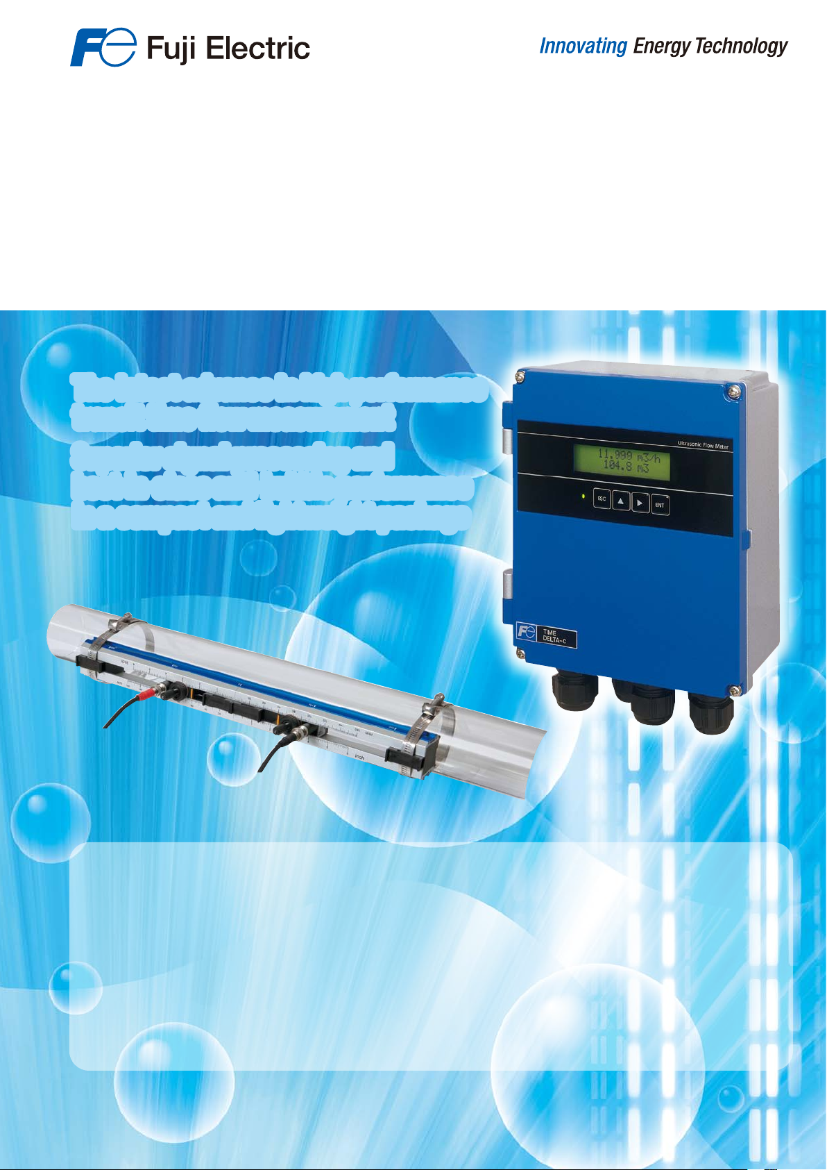
The latest advance in high performance
The latest advance in high performance
transit time flow measurement
transit time flow measurement
Superior signal processing and
Superior signal processing and
best-in-class anti-bubble performance
best-in-class anti-bubble performance
in a compact and lightweight package
in a compact and lightweight package
TIME DELTA-C
Detector (FSSC)
■
High accuracy measurement : 1.0% of rate
■
Superior anti-bubble performance : Our Advanced ABM method
Maintenance free operation : Non-invasive setup with no moving parts
■
Compact and lightweight : Size and mass reduced by 2/3 (compared with model FLV).
■
Flexible communication functions : RS-485 (MODBUS) (option)
■
Wide application range : φ13 to φ6000mm applicable pipe diameters
■
Extendable rail type detector up to φ50 to φ1200mm
Quick and easy setup : Simple menu guided setup from the front panel or PC interface
■
* Advanced ABM method: anti-bubble measuring method.
*
Flow transmitter (FSV...S)
is adopted.
21A1-E-0016b
Page 2
12
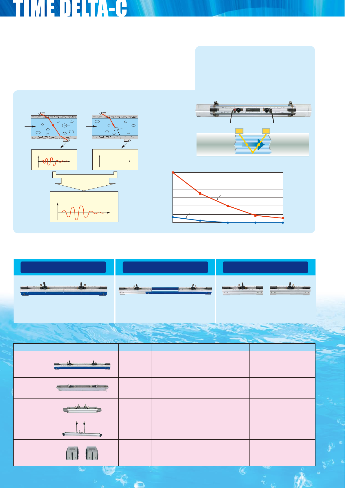
●Advanced received signal digital processing results in higher performance
Applicable pipe diameter is
High accuracy measurement of fluid flow rate: 1.0% of rate
■
Quick response: 0.2 sec. or less (quick response mode)
■
Minimal Influence by the pressure of measured fluid and temperature
■
Superior anti-bubble performance
■
φ
13mm to
■
(Advanced AMB method * is adopted.)
Advanced ABM method: anti-bubble measurement method
*
flow measurement
Normal propagation
Propagation interrupted by bubble
φ
6000mm
Measuring principle
With ultrasonic pulses propagated diagonally
between the upstream and downstream sensors
mounted on the exterior of the pipe, the flow rate
is measured by detecting the time difference
caused by the flow.
Flow
Received signal :
v
Summed 128 or 256 times
Digital data of the received signals :
v
Synchronized summation of received signals
Flow
Bubble
t
for a single output
Received signal :
v
Nothing
t
Bubble
In the case of an analog
system, measurement
t
failure will occur.
Sensor Sensor
12
Acceptable value
of bubble quantity
10
8
6
4
2
[vol.%]
1.2
1
1.0 2.0 3.0 4.0 5.0
(Note) Flowmeter indicates the volumetric flow
rate, including bubbles.
7.0
Advanced ABM method
4.0
Conventional method
0.4
0.03
1.5
0.02
Explanation of the extendable rail type detector
Normal Extended on rails Z method
1.0
0.02
Flow velocity
[m/s]
(type: FSSC)
pipe diameter φ50 to φ300mm <V method> pipe diameter up to φ600mm <V method> pipe diameter up to φ1200mm <Z method>
(A detector is simply attached to the exterior of the piping.)
Classification Appearance Detector type
Extendable rail
type
Compact type
Small
diameter type
High
temperature
type
Large
diameter type
FSSC
FSSA
FSSD
FSSH
FSSE
Applicable pipe inner diameter (mm)
50 to φ1200
φ
25 to φ225
φ
13 to φ100
φ
50 to φ400
φ
200 to φ6000
φ
(rail removed)
Measured fluid temperature
-
20 to 120°C
-
20 to 100°C
-
40 to 100°C
-
40 to 200°C
-
40 to 80°C
Mounting/structure
V or Z method mounting
・
Jet structure (equivalent to
・
IP65)
Submersible type available
・
V method mounting
・
Jet structure (equivalent to
・
IP65)
V mounting method
・
Splash-proof structure
・
(equivalent to IP52)
V or Z method mounting
・
Splash-proof structure
・
(equivalent to IP52)
V or Z method mounting
・
Watertight structure
・
(equivalent to IP67)
Submersible type available
・
2
Page 3
Normal: green / Extraordinary: Red
Instantaneous flow velocity
value (8-digit display)
Total flow rate value
(8-digit display)
Waterproof keypad
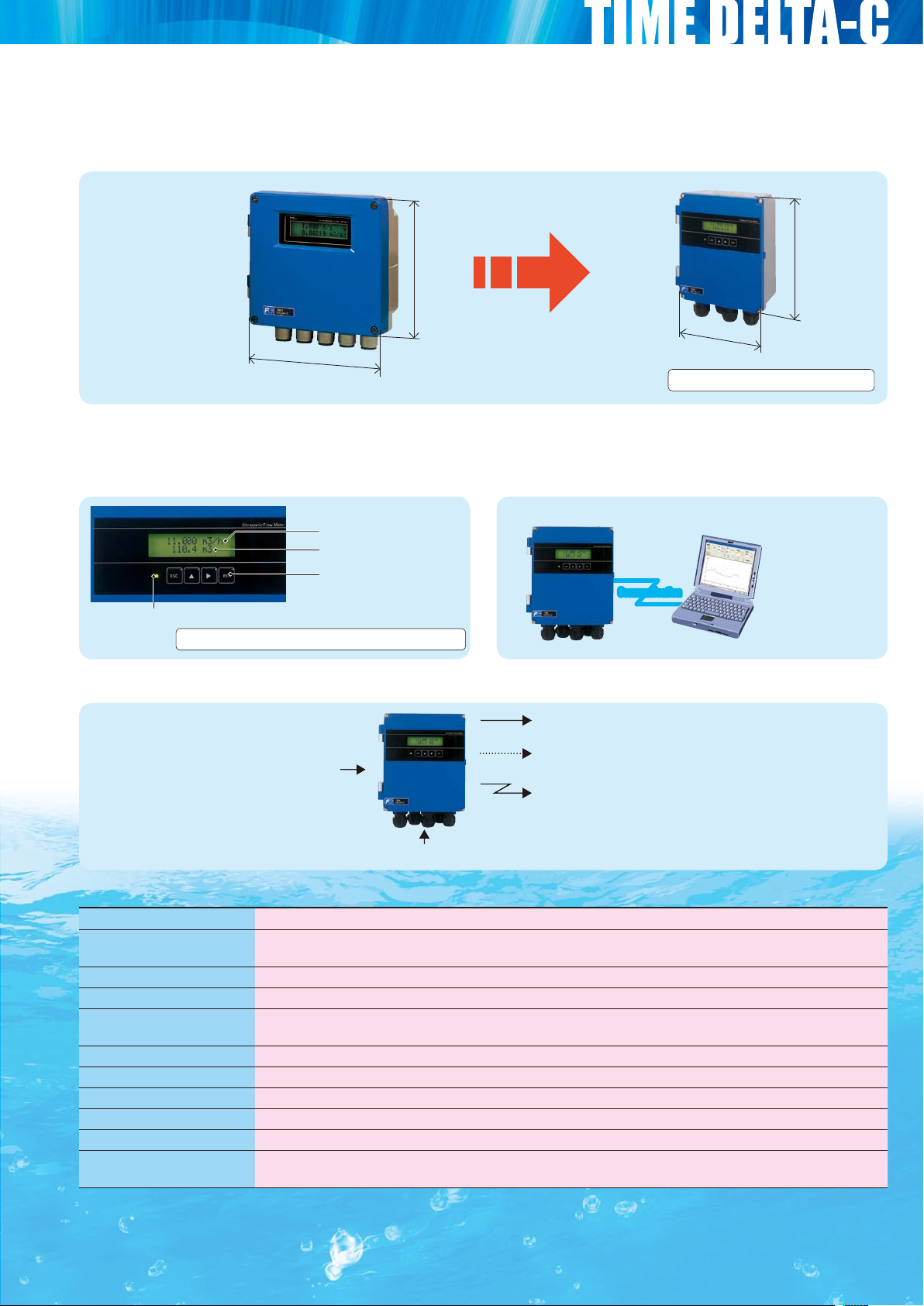
Both the mass and volume of the ow transmitter are reduced by 2/3!
Compact and lightweight flow transmitter (1/3 size of model FLV)
■
Easy to carry and install on a system
<Our FLV type> <Our FSV type>
170mm
220mm
Mass: approx 4.5kg Mass: approx 1.5kg
230mm
Operation can be performed from the outside panel
■
(In case of IP66 type)
Various settings can be made from the front side without opening the cover
of the flow transmitter. (Parameter setting , input of mou nted pipe data,
automatic calculation of mounting dimensions and similar)
LCD display with backlight is clearly legible, even in dark places.
Signal and process interfaces are designed with functionality as priority.
■
Input signal from the detector
Parameter setting and data collection can be
■
performed via optional PC communications
interface.
RS485
CommunicationCommunication
Analog output 1 point (4 to 20mA, insulated)
(max. load resistance: 600Ω)
Transistor contact 2 points (insulated)
Output frequency: 100P/s max., pulse width 5 to 1000ms)
Communication signal (RS485 communication)
(Insulated)
142mm
Mounting method: wall or pipe mounting
PC loader software
for the setting of
various parameters
and the collection of
measured data is a
standard accessory
Power supply voltage (with arrester, 100 to 240VAC or 20 to 30VDC)
Fully equipped with extensive functions
■
Zero adjustment one-touch adjustment while the flow is stopped
Damping
Low flow rate cut Output may be cut when the flow rate is low. Setting range: 0 to 5m/s (setting in 0.01m/s unit)
Alarm contact output Contact output at condition of hardware and process faults
Output burnout
Forward and backward ranges Ranges may be set arbitrarily. The digital output of the operation range is available.
Auto 2-range 2 forward ranges are independently configurable. Digital output of operation is available.
Flow switch Contact output is made when the upper or lower limit values of the instantaneous flow rate are reached
Total value switch Contact output is made when the upper limit value of the total flow rate (forward) exceeds the setting value.
Display of various units Unit may be set in
Multilingual display
Related products
■
Our product lineup includes such models as: consumed energy calculation, simultaneous measurement of 2 pipes, dual-path measurement.
Refer to the catalog No. 21A1-E-0024)
(
Used to reduce the fluctuation of the measured value.
Setting range: 0 to 100 sec. (setting per 0.1 sec.)
When measurement cannot be made because the pipe is empty or bubbles are entrained in the fluid, contact output is
activated while analog output is held.
m/s, L/s, L/min, L/h, L/d, KL/d, ML/d, m3/s, m3/min, m3/h, m3/d, Km3/d, Mm3/d
The display language may be selected from 5 choices, including Japanese (Katakana), English, French, Spanish and
German.
3
Page 4

Semi-conductor
underground water
condominiums and buildings
Pump
Application example
The ultrasonic flowmeter is a liquid flowmeter used in various applications.
■
1. Measuring system for the paint flow rate
The flow rate of thick paint is measured by a detector mounted on the pipe already constructed.
Ultrasonic
flowmeter
Paint
(red)
Flow
transmitter
Detector
Ultrasonic
flowmeter
Paint
(blue)
Flow
transmitter
Detector
Ultrasonic
flowmeter
Paint
(yellow)
Flow
transmitter
Detector
2. An energy-saving system for measuring and controlling the flow rate of a pump
A detector is attached to the already constructed pipe to measure the flow rate at the pump outlet, and a regulator is used to implement
inverter control of the pump.
Ultrasonic
flowmeter
Flow transmitter
(type: FSV)
Detector
(type: FSSC)
Pump
Inverter
Pump
Flow rate regulator
(type: PXH)
Water supplyWater supply
Application: To pump
3. Flow rate measurement in a water purifying
system for semi-conductors
Advantages of using an ultrasonic flowmeter for the system
Application: Water supply to high-rise
4.
Consumed energy calculation function
Calculates the thermal energy received and sent with liquid (water)
in cooling and heating.
1) It can be easily mounted on the exterior of a pipe, helping reduce
mounting cost.
2) As a sensor, it can operate without coming into contact with fluid, so the
fluid is not affected by metallic ions.
3) This meter, compact and lightweight, can be easily carried and mounted.
Ultrapure water
is supplied
manufacturing device
Electromagnetic
flowmeter
Raw
water
Ultrasonic
flowmeter
Detector
(type: FSSA)
Flow transmitter
(type: FSV)
Measurement of
the raw water
flow rate
Major applications
■
• Backup for the already constructed flowmeter
• Water supply and sewage systems ..........
• Power plant .................................................
• Various plants .............................................flow rate measurement of cooling water, plating solution and corrosive liquid
• Food manufacturing plan ...........................flow rate measurement of raw material and washing water
• Semiconductor manufacturing plant .........flow rate measurement of pure water
• Air-conditioning equipment .......................flow rate measurement of hot water and chilled water in heating and cooling
• Hot spring ...................................................Measurement of suction quantity
It can be mounted on the pipe already constructed.
・
Small, lightweight and easy to mount
・
Consumed heat quantity signal
Flow transmitter
(type: FSV...L)
Refer to the catalog
No. 21A1-E-0024
source
Heat
TR: Temperature of the heating
medium of the receiving side
leakage investigation of water pipe and investigation of the flow direction in the water distribution pipe
flow rate measurement of the boiler water supply, condenser circulating pump and turbine oil
)
Temperature
sensor
S: Temperature of the
T
heating medium on
the emitting side
Temperature
sensor
(4 to 20mADC)
Heat quantity total value pulse signal
(DO)
Consumed heat quantity
q = K · Q · |T
K : heat quantity (calorie)
conversion factor
(For heating K = 4.123)
(For cooling K = 4.186)
Q: Flow rate of the
heating medium
S–TR|
Detector
(type: FSSA)
Load
4
Page 5

Example of system conguration
5.5
Flow transmiter (Type: FSV)
Signal cable (Type: FLY)
Detector (Type: FSS)
< V method >
Detector (Type: FSS)
Power Supply
RS-485
Communication
4 to 20mA DC
Pulse output
Paperless recorder (Type: PHF)
Integrator
< Z method >
CODE SYMBOL
Flow transmitter
■
IP66
1 2 3 4 5 6 7 8 9 1011 1213
F S V Y 2 ー Y Description
E
Y
D
Y
1
4
S
H
Y
A
Detector
■
1 2 3 4 5 6 7 8 9 10
F S S 1 1 ー Description
C Extendable rail type (φ50 to φ1200mm)
A Compact type (φ25 to φ225mm)
D Small diameter type (φ13 to φ100mm)
E Large diameter type (φ200 to φ6000mm)
H High temperature type (φ50 to φ400mm)
1 Provided
Y None
A Stainless belt (1.0m×2)
C SS belt fasten with screws (1.0m×4)
D Wire ≤ φ1500mm
E Wire ≤ φ6000mm
Y None
A Silicon rubber (KE348)
B Silicone-free grease (HIGH-Z)
C Silicone grease (G40M)
Y None
A Provided (with signal cable 10m) *2
Y None
A Provided
(Language) (4th digits)
Standard
(Communication) (5th digit)
None
RS485
(6th digit)
Single measuring path
(Power supply) (7th digit)
100 to 240VAC 50/65H
20 to 30VDC
(Case structure) (9th digit)
IP66
IP67
(Wire connection port) (10th digit)
Weatherproof gland provided
Union (for plica) with gland [G1/ 2 female
screw] (when "H" is specied 9th digit)
(Combination with an explosion-proof detector) (11th digit)
None
Y
(Parameter setting) (12th digit)
None
Y
Setting provided
A
Setting provided + tag
B
Tag
C
(Mounting method) (13th digit)
Pipe mount (if the 9th digit is S)
A
Wall mount
B
Pipe mount (if the 9th digit is H)
C
<Senser type> (4th digit)
<Guide rall> (5th digit)
<Mounting belt> (6th digit)
<Acoustic coupler> (7th digit) *1
<Watwe-proof treatment> (9th digit)
<Tag plate> (10th digit)
(
) (
IP67
Contact output
Signal cable
■
)
1 2 3 4 5 6 7 8
F L Y 1 Description
D For FSSA, FSSC, FSSD, FSSH, FSSE (Note)
<Cable length: m> (5, 6, 7digits)
0 0 5 5m
0 1 0 10m
0 1 5 15m
0 2 0 20m
0 2 5 25m
0 3 0 30m
0 3 5 35m
0 4 0 40m
0 4 5 45m
0 5 0 50m
0 5 5 55m
0 6 0 60m
0 6 5 65m
0 7 0 70m
0 7 5 75m
0 8 0 80m
0 8 5 85m
0 9 0 90m
0 9 5 95m
1 0 0 100m
1 1 0 110m
1 2 0 120m
1 3 0 130m
1 4 0 140m
1 5 0 150m
Z Z Z Others (Contact us)
Note) When detector is FSSA,length of signal cable is up to 60 m.
Outline diagram det ecter signal cord
ø3.2
Bar terminal
<Type of detector> (4th digit)
L (cable length (m) : specified by order)
Relay
ø11
ø7.3
30
To DetectorTo Flow transmitter
SCOPE OF DELIVERY
• Flow transmitter
(provided with U-bolt and nuts for pipe mount)
•
Detector
(provided with mounting fixture and acoustic coupler)
• Signal cable
• CD-ROM (contains instruction manual, loader software)
*1) Normally select silicone rubber as acoustic coupler. Silicone rubber in tube (100g)
is furnished. If you place an order for several units, 1 tube may suce for every 5
units.
Select silicone -free grease for semiconductor manufacturing equipment or the
like that is vulnerable to silicone. The silicone-free grease is water-soluble and ,
therefore, cannot be used in environment exposed to water or on piping subjected
to a condensation. Since the grease does not set, a periodic maintenance
(cleaning, relling every about 6 months at normal temperature) is necessary.
* 2) It is selectable only for FS SC type and FSS E type.
ø14.5
BNC connector
5
Page 6

Specications
Applicable subjects and operation environment
■
Applicable fluid Homogeneous liquids capable of ultrasonic wave propagation
Bubble quantity: 0 to 12Vol% (reference diameter 50A, water and flow velocity of 1m/s)
Turbidity of fluid: 10000 degrees (mg/L) or less
Straight pipe length: upstream side 10D or more, downstream 5D or more (D: pipe inner diameter)
State of flow: fully developed turbulent or laminar flow in round pipe filled with fluid
Applicable piping and
fluid temperature
Flow velocity range 0 to ±0.3
Power supply voltage 100 to 240VAC 50/60Hz or 20 to 30VDC
Power consumption 15VA or less (AC power supply), 6W or less (DC power supply)
Signal cable (between the
detector and converter)
Installation environment Non-explosive area not exposed to direct sunlight, corrosive gas or heat radiation
Ambient temperature Flow transmitter: -20 to 55°C
Ambient moisture 90% RH max.
Grounding Class D (100Ω)
Arrester Provided as standard at the power supply
Classifi cation
Compact type FSSA
Extendable rail type FSSC
Small diameter type FSSD 13 to 100 V method -40 to +100
Large diameter type FSSE
High temperature type FSSH
Note 1) Please select the FSSC type and FSSE type if following condition.
- When pipe material is PP and pipe wall thickness is 15mm or more
- When pipe material is PVDF and pipe wall thickness is 9mm or more"
- When pipe material is cast iron pipe, lining pipe, old steel pipe or others through which the ultrasonic signal could not be transmitted easily.
Lining material: Tar epoxy, mortar, rubber, etc.
* If the lining is not properly glued to a pipe, the measurement may be impossible.
Note 2) If silicone-free grease is used as an acoustic couplant, the fl uid temperature range is 0 to 60°C, regardless of the detector.
Note 3) Please order a guide rail separately for Z method mounting. Order number : ZZP*TK4J5917C3
.....
±32m/s
Coaxial cable (60m max. for compact type detector (FSSA), 300m max. for others)
Heat resistance: 80°C
Detector: -20 to 60°C
Detector
type
Pipe size (inner diameter)
25to50
50to225
50to600
300to1200
200 to 1000 V method
500to6000
50to200
150 to 400 Z method
φ
(mm)
Mounting method
V method -20 to +100
V method
Z method
Z method
V method
Fluid temperature range
(°C) (Note 2)
-40 to +120
-40 to +80
-40 to +200
Applicable pipe material
(Note 1)
Plastic (PVC, Others)
Plastic (PVC, Others)
Metal pipe (Stainless
steel, Carbon steel,
Copper, Aluminum,
Others)
Performance specifications
■
Accuracy
rating
Response
time
Classifi cation Detector type Pipe size (inner diameter)
Compact
type
Extendable
rail type
Small
diameter
type
Large
diameter
type
High
temperature
type
0.5 sec. (standard mode), 0.2 sec. depending on setting (quick response mode)
FSSA
FSSC
FSSD
FSSE
FSSH
(mm)
φ
25to50
50to225
50to200
200to1200
13to50
50to100
200to300
300to1200
1200to6000
50to200
150to400
Flow velocity
(m/s)
3 to 32 ±2.0% of rate -
0 to 2 ±0.04m/s -
2 to 32 ±1.0% of rate ±2.0% of rate
0 to 2 ±0.02m/s ±0.04m/s
2 to 32 ±1.5% of rate
0 to 2 ±0.03m/s
2 to 32 ±1.0% of rate
0 to 2 ±0.02m/s
2 to 32 ±1.5% to ±2.5% of rate
0 to 2 ±0.03 to ±0.05m/s
2 to 32 ±1.5% of rate
0 to 2 ±0.03m/s
2 to 32 ±1.5% of rate
0 to 2 ±0.03m/s
0.75 to 32 ±1.5% of rate
0 to 0.75 ±0.0113m/s
1 to 32 ±1.0% of rate
0 to 1 ±0.02m/s
2 to 32 ±1.0% of rate
0 to 2 ±0.02m/s
0.75 to 32 ±1.0% of rate
0 to 0.75 ±0.0075m/s
Accuracy
Plastic pipe Metal pipe
6
Page 7

Functional specifications
■
Analog signal 4 to 20mA DC (1 point), Load resistance: 600Ω max.
Digital output
Serial communication
RS-485
(option)
Display device 2-color LED (Normal: green, Abnormal: red), LCD display (2 lines of 16 digits, back light provided)
Indication language Japanese (Katakana), English, French, German, Spanish (switchable)
Flow velocity / Instantaneous flow velocity / instantaneous flow rate indication (minus indication for reverse flow)
flow rate indication Numerals: 8 digits (decimal point is counted as 1 digit) English and metric units selectable.
Total indication Forward or reverse total value indication (negative indication for reverse direction)
Setting function Setting available with 4 keys (ESC, △, ▷, ENT) on the flowmeter front
Zero adjustment Set zero/Clear available
Damping 0 to 100s (setting per 0.1 sec.) for analog output and flow velocity/flow rate indication
Low flow rate cutoff 0 to 5m/s in terms of flow velocity
Alarm Digital output available for Hardware fault or Process fault
Burnout Analog output: Hold /Over-scale/Under-scale/zero (selectable)
Bi-directional range Forward and reverse ranges configurable independently / Hysteresis: 0 to 20% of working range / Working range applicable to digital output
Auto 2-range 2 forward ranges configurable independently / Hysteresis: 0 to 10% of working range / Working range applicable to digital output
Flow switch Lower limit, upper limit configurable independently (Digital output available for status at actuated point)
Total switch Upper limit of the forward total settable (Digital output available when actuated)
External total preset Preset total settable upon contact input setting
Backup of power failure backup by non-volatile memory
Forward total, reverse total, alarm, acting range, flow switch, total switch assignable arbitrarily
Transistor contact (isolated, open collector)
・Output: 2 points
・Normal: ON/OFF selectable
・Contact capacity: 30VDC, 50mA
・Output frequency: 100P/s max. (pulse width: 5, 10, 50, 100, 200, 500, 1000ms)
RS-485(MODBUS), isolated
Connectable quantity: 31 units
Baud rate: 9600, 19200, 38400bps
Parity: None/Odd/Even selectable
Velocity m/s ft/s
Unit:
Flow rate L/s, L/min, L/h, L/d, kL/d, ML/d, m
Numerals: 8 digits (decimal point is counted as 1 digit) English and metric units selectable.
Unit:
Total mL, L, m
Flow rate total: Hold/Count (selectable)
Burnout timer: 0 to 100s (every 1s)
Metric system Inch system
3
3
/d, BBL/s, BBL/min, BBL/h, BBL/d, kBBL/d, MBBL/d
Mm
Metric system Inch system
3
, km3, Mm3, mBBL, BBL, KBBL gal, kgal, ft3, kft3, Mft3, mBBL, BBL, kBBL, ACRE-ft
/s, m3/min, m3/d, km3/d,
Stop bits: 1 or 2 bits selectable
Cable length: 1km max.
Data: Flow velocity, flow rate, forward total, reverse total, status, etc.
gal/s, gal/min, gal/h, gal/d, kgal/d, Mgal/d, ft
3
/d, BBL/s, BBL/min, BBL/h, BBL/d, kBBL/d, MBBL/d
d, Mft
3
/s, ft3/min, ft3/d, Kft3/
Physical specifications
■
Type of enclosure Flow transmitter: IP66 or IP67
Mounting method Mounted on wall or by 2B pipe / Detector: Clamped on existing piping.
Acoustic couplant Silicone rubber, silicone grease or silicone-free grease
Note: The acoustic couplant
is a medium that eliminates
the gap between detector
and pipe.
Outer dimensions, mass See outline diagrams.
Loader software (standard accessory)
■
Compatible PC model PC/AT compatible instrument
Main function Software for setting/change of the main unit parameters and for collection of the measured data on PC
OS Windows 2000/XP/7/8
Memory requirement 125MB min.
Hard disk capacity Minimum free space of 52MB or more
Type
Fluid temperature -40 to +150˚C
Teflon piping Not usable Good Good Good
Silicone rubber (type:KE-348W)
Silicone grease (type:G40M)
30 to +150˚C 0 to +60˚C
-
Silicone-free grease (type:HIGH Z)
Connection diagram
Earth terminal
(M4)
AC power supply DC power supply
1
L
AC100 to 240V
32
N FG FG
+
DC20 to 30V
50/60Hz
<Plug terminal>
3
21
−
+
DO1
TR out
Max. DC30V, 50mA
3 421
− −
+
DO2
TR out
5 6
−
+
output
4 to 20mA
DC
7
GND
8
GND
HF1
To downstream-side
sensor
109
HF2
To upstream-side sensor
Grease for high temperature (type:KS62M)
30 to +250˚C
-
Option
●
21
SG
A
−
RS-485
3
B
+
7
Page 8

2-
U-bolt (M8) (option)
Mounting plate
Information in this catalog is subject to change without notice.
Outline diagram of the flow transmitter (unit: mm)
SS tag
BNC
Spacing 0 to 330
Saddle
Spacing
Name plate
10
TIME
DELTA-C
(Weight: 1.5kg)
142
701 1
ENT
ESC
10
9
Ultrasonic Flow Meter
IP66 type Flow transmitter Type: FSV...S
●
2.5
75
2.5
U-bolt (M8)
(option)
SS tag
Mounting Pipe
(2B)
(option)
Mounting hole 9x10
200
170
(233)
IP67 type flow transmitter Type FSV···H
●
20
220
312
277
25
(Weight: 4.5kg)
φ9
72
Cable gland
Earth terminal (M4)
For power supply/output cable (PG13.5)
Outline diagram of detector (unit: mm)
Extendable rail type detector Type: FSSC
●
±2
480
SPACING: 0 t o 300
mm
Scale (m m)
Lock nu t
Exte nded rail
Saddle
160 140 120 100 80 6 0 40 20
654321 inch
Name pl ate
53
54
Guide r ail
654321 inch
160 140 120 100 80 6 0 40 20
mm
Scale ( inch)
BNC CON N.
Rail end
Tag plate
<Shipmentstyle(Vmethod)>
High-temperature sensor
●
Type: FSSH
Scale
(inch)
(diameter φ50 to φ400, Weight: 1.6kg)
connector
Scale
(mm)
153
For sensor
cable (PF3/8)
(diameter φ50 to φ1200, Weight: 1kg)
(880)
700ma x.
400m ax.
Exte nded rail
mm
100 100
88ma x.
Rail end ( Accessor ies)
654321 inch
160 140 120 100 80 6 0 40 20
<Extendedstyle(Longest,Vmethod)>
240 2 40
<Sepalatestyle(Zmet hod)>
Small diameter sensor
●
Type: FSSD
(diameter φ13 to φ100, Weight: 0.6kg)
Bracket
(option)
240
100 100
14 230
5.7 95
Mounting Pipe
93
4040 40 40
For power supply/output cable (PF1/2) For sensor cable (PF1/2)
Compact type detector
●
Type: FSSA
mm
160 140 120 100 80 6 0 40 20
654321 inch
(option)
Large diameter sensor
●
Type: FSSE
(diameter φ25 to φ225, Weight: 0.4kg)
348
Sensor
BNC connector
Frame
Spacing
(Adjustment by every 3mm)
Lock clip
(diameter φ200 to φ6000, Weight: 1.2kg)
Earth terminal
30
(50)
34
28
Name plate
Scale
(inch)
530
Lock nut
Element holder
0 to 133
Cursor
Cursor
φ26
205max
90max
33
44
Caution on Safety
* Before using products in this catalog, be sure to read their instruction manuals in advance.
Grobal Sales Section
Instrumentation & Sensors Planning Dept.
1, Fuji-machi, Hino-city, Tokyo 191-8502, Japan
http://www.fujielectric.com
Phone: +81-42-514-8930 Fax: +81-42-583-8275
http://www.fujielectric.com/products/instruments/
inch
mm
52.5
Scale
(mm)
Element holder
90max
BNC
connector
Lock nut
320
78±1
Sensor
84±1
Wire rope
Mounting spring
114
67±1
36
φ4.3
8
150
BNC connector
φ7.3
±10
19
Signal cable conversion cord (accessories)
Printed in Japan 2015-5FOLS
 Loading...