

Page 1

Instruction Manual
PC LOADER SOFTWARE
FOR MAINTENANCE
FOR HYBRID ULTRASONIC
FLOWMETER
<Duosonics>
TYPE: FSH-1
INF-TN514459-E
Page 2

Page 3

Contents
1. COPYRIGHT OF THIS SOFTWARE ...................................................................................1
2. OUTLINE .................................................................................................................................1
3. PC TO BE USED......................................................................................................................1
3.1. Computer .............................................................................................................................1
3.2. Memory capacity .................................................................................................................1
3.3. Interface...............................................................................................................................1
3.4. OS........................................................................................................................................1
3.5. Communication cable..........................................................................................................1
3.5.1. When using communication port for maintenance (RS232C)......................................1
3.5.2. When using communication port open to users (RS232C/RS485)...............................1
4. INSTALLING OF SOFTWARE .............................................................................................2
5. STARTUP METHOD ..............................................................................................................5
5.1. Communications..................................................................................................................6
5.2. Setting..................................................................................................................................7
5.2.1. Save setting...................................................................................................................7
5.2.2. Read setting ..................................................................................................................7
5.3. Version .................................................................................................................................8
6. STRUCTURE OF FUNCTION ..............................................................................................8
7. ESTABLISH SETTING...........................................................................................................9
8. RANGE SETTING ................................................................................................................11
9. TOTAL SETTING..................................................................................................................13
10. STATUS OUTPUT SETTING ............................................................................................15
11. DISPLAY SETTING............................................................................................................16
12. SYSTEM SETTING ............................................................................................................17
13. MEASUREMENT................................................................................................................18
14. PULSE DOPPLER MEASUREMENT..............................................................................19
14.1. Detailed setting................................................................................................................19
14.2. Flow velocity profile .......................................................................................................21
14.3. Operation Information.....................................................................................................22
15. TRANSIT TIME DIFFERENCE MEASUREMENT.......................................................24
15.1. Detailed Setting ...............................................................................................................24
15.2. Received Signal...............................................................................................................26
15.3. Operation Information.....................................................................................................27
16. RAS/STATUS........................................................................................................................29
16.1. RAS .................................................................................................................................29
16.2. Status ...............................................................................................................................30
16.3. RAS detail setting............................................................................................................31
17. MAINTENANCE .................................................................................................................33
18. SUPPORT.............................................................................................................................35
INF-TN514459-E
- i -
Page 4

19. END ...................................................................................................................................... 37
20. UNINSTALLING OF SOFTWARE ................................................................................... 37
- ii -
INF-TN514459-E
Page 5

1. COPYRIGHT OF THIS SOFTWARE
The copyright of this software belongs to Fuji Electric Systems Co., Ltd. No part of this software may be reproduced
or transmitted in any form.
2. OUTLINE
Using this software, you can set, read and display relevant graphs of the hybrid ultrasonic flow meter on your PC with
ease. Your data can be easily edited with Microsoft Excel because you can save your data in CSV file format.
Note: Microsoft Excel is the registered Trademark of the Microsoft Corporation in the United States.
3. PC TO BE USED
3.1. Computer
AT compatible-type with CPU Pentium IV 1 GHz/Celeron 1 GHz or more installed, display resolution of 1024 × 768,
and use of small font recommended.
3.2. Memory capacity
128 MB or more (256 MB or more recommended) [52 MB memory or more for free space required]
3.3. Interface
RS232C port or RS485 port
3.4. OS
Microsoft Windows2000 Professional (SP6a or more) or Microsoft WindowsXP Professional (SP1 or more)
3.5. Communication cable
There are two types of interfaces for flow transmitter.
3.5.1. When using communication port for maintenance (RS232C)
Use the following cable for communications between PC communication port and flow transmitter (control board CN6).
• Dedicated communication cable for digital controller
Type: PDZL1001
3.5.2. When using communication port open to users (RS232C/RS485)
Use the following cable for communications between PC communication port and flow transmitter (control board
terminal box).
• PC loader communication cable
Type: ZZP
B TK4H6253
*
INF-TN514459-E
- 1 -
Page 6
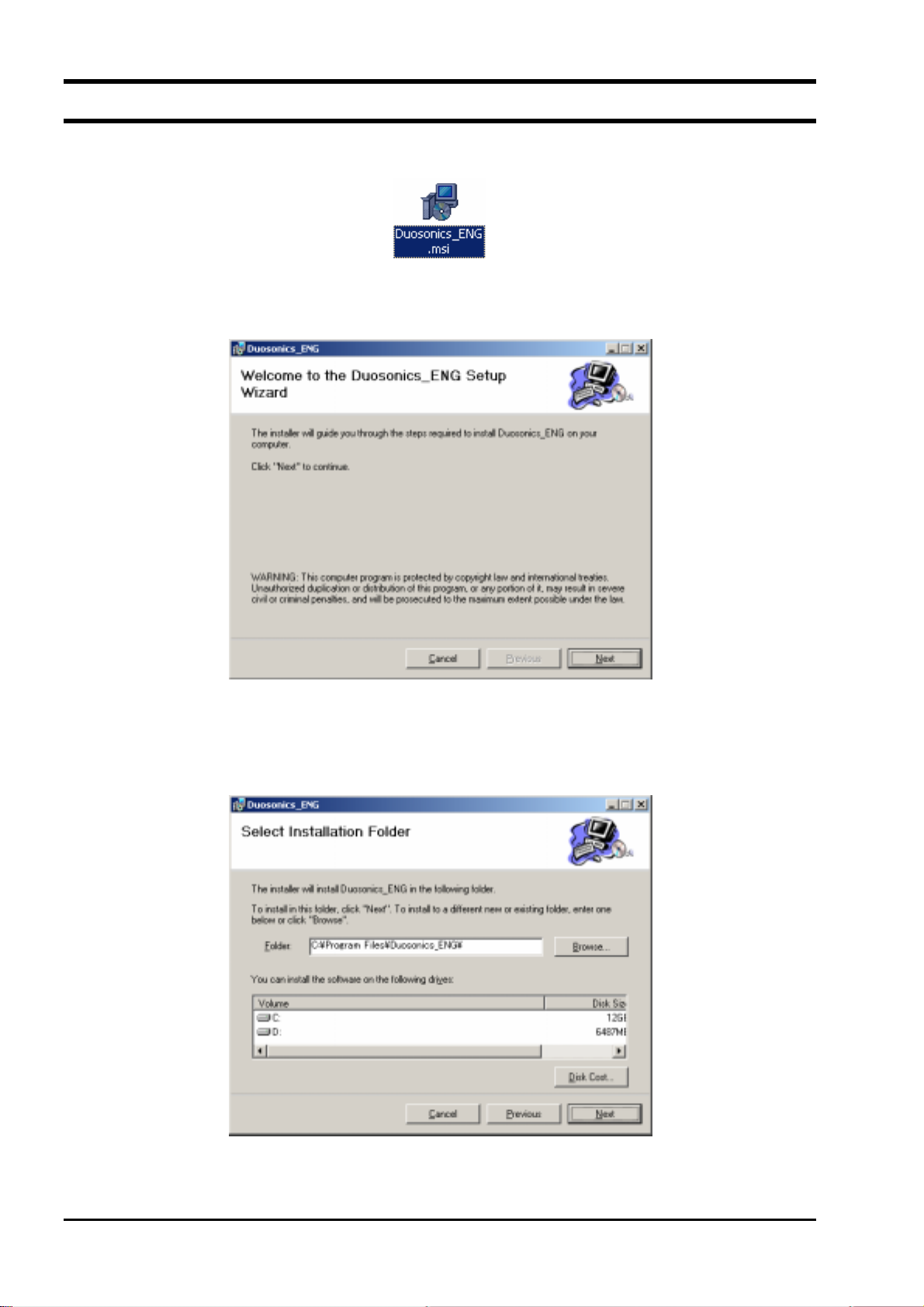
4. INSTALLING OF SOFTWARE
(1) Insert the setup disk into the drive, and double-click “Duosonics_ENG.msi”.
Fig. 1 <File Installation>
(2) Setting wizard will start up. Click the [Next] button. Click the [Cancel] button to cancel the installation.
Fig. 2 <Setup wizard screen>
(3) There is a query about selection of installation folder. Click the [Next] button to install the software in that folder.
To specify a folder click the [Browse] button and select, or enter directly. To return to the previous screen, click
the [Previous] button. Click the [Cancel] button to cancel the installation.
Fig. 3 <Select installation folder screen>
- 2 -
INF-TN514459-E
Page 7
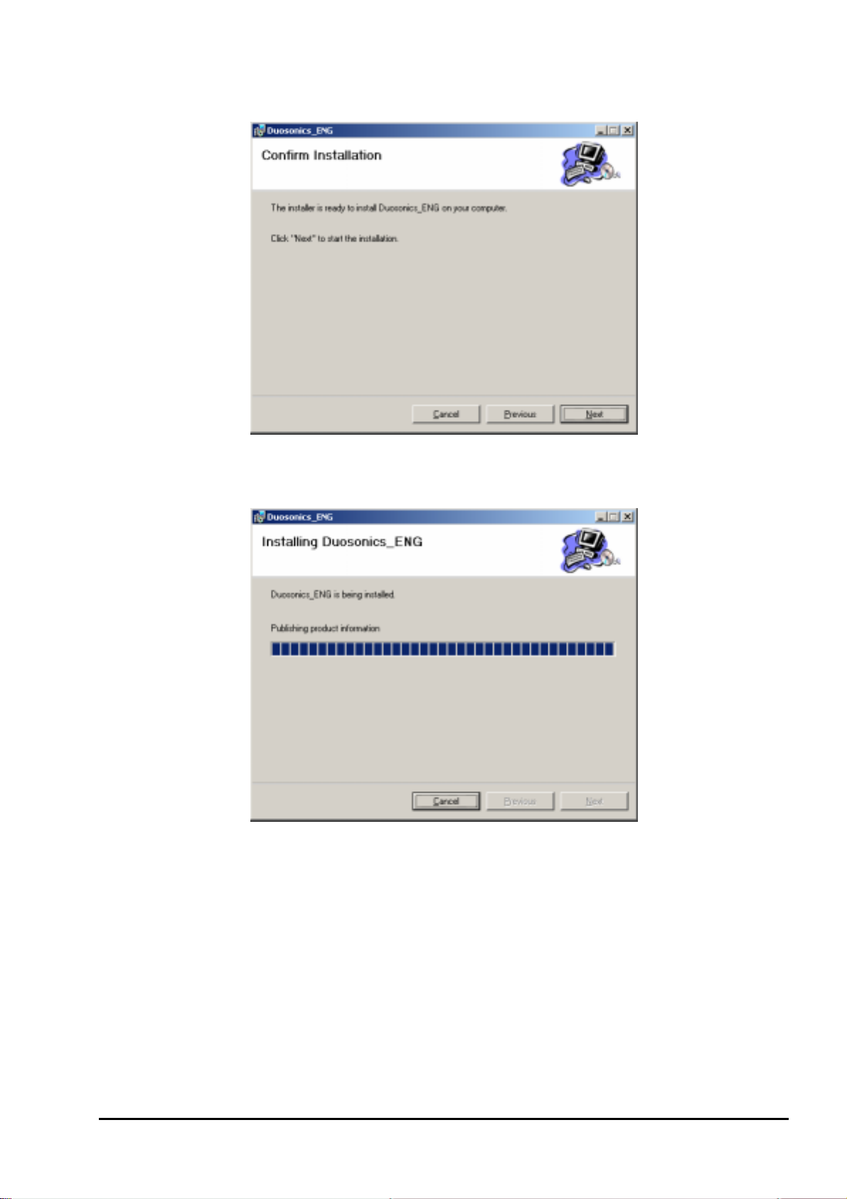
(4) Screen is displayed to confirm installation. Click the [Next] button to execute the installation. Click the
[Previous] button to return to the previous screen. Click the [Cancel] button to cancel the installation.
Fig. 4 <Installation confirmation screen>
(5) Execution of Installation
INF-TN514459-E
Fig. 5 <Installing screen>
- 3 -
Page 8
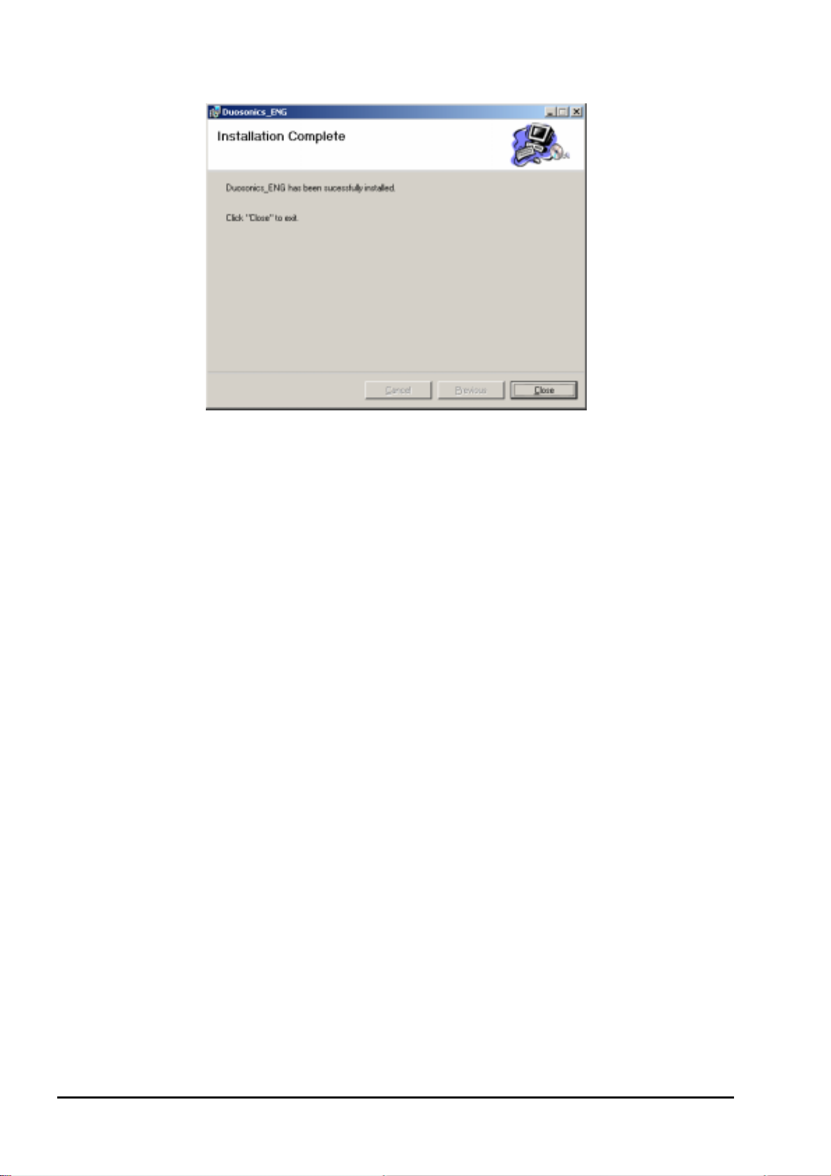
(6) The Installation Complete screen is displayed. Click the [Close] button to exit the installation screen.
Fig. 6 <Installation complete screen>
(7) After installation, the start menu and the application (“Duosonics_ENG”) that has been installed in the disktop are
created.
- 4 -
INF-TN514459-E
Page 9
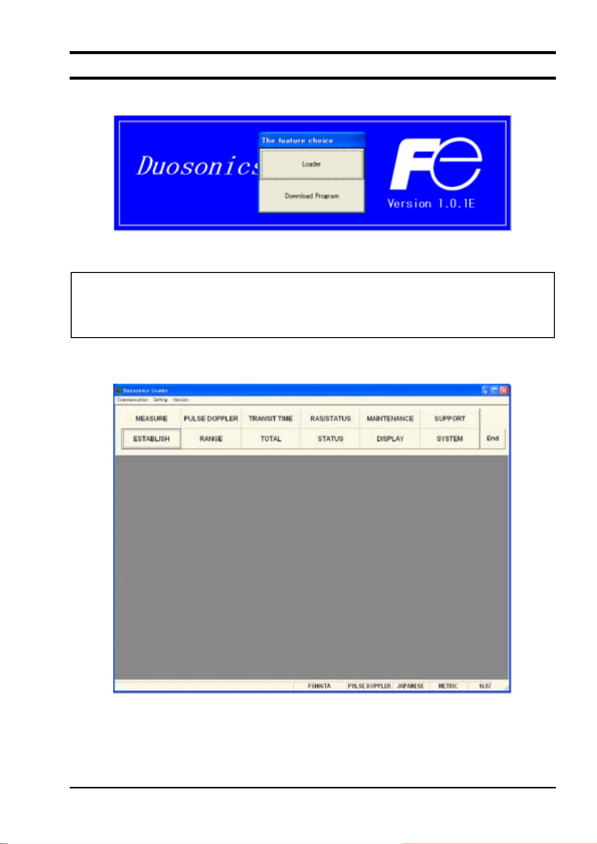
5. STARTUP METHOD
Start “Duosonics_ENG” from the start menu to start up the loader.
Fig. 7 <Start screen>
Click the [Loader] button to start up the loader.
Click the [Download Program] button to start up the download program application. Click the button to upgrade
the software of the flow transmitter. Do not click it in ordinary cases.
Click the [Loader] button to start up the loader, and communication with the flow transmitter is carried out and the
system name, measurement method, language, and unit information is acquired.
If error occurs during communications, an error message is displayed to continue communication, select [Continue].
To stop communication, select [Cancel] on the menu screen that appears, check the setting for “Communication.”
Fig. 8 <Menu screen>
Click the menu bar and each function button to execute a desired function.
INF-TN514459-E
- 5 -
Page 10
5.1. Communications
Click “Communication” on the menu bar on the Menu screen, and the following setup screen appears.
Fig. 9 <Serial communication setup screen>
Click the [Setting] button, and setting content is reflected; communications are executed with the flow transmitter and
information related to system name, measurement method, language and unit is obtained. Click the [Cancel] button to
invalidate the setting.
Table 1 <Measurement and Detailed Setting>
Item Content
Port No. Select either from COM1, COM2, COM3, COM4 and COM5.
Serial Method Select either RS232C or RS485.
Station No. Select one from 01 to 31. If communication method is RS232C, no selection is
allowed (fixed with 00).
Speed Select one from 9600BPS, 19200BPS and 38400BPS.
Parity Select one from NONE, EVEN and ODD.
Stop Bit Select either 1-bit or 2-bit.
Wait time Specify in the range from 1 to 65535. (Unit: msec)
Retry Specify in the range from 0 to 5.
- 6 -
INF-TN514459-E
Page 11
5.2. Setting
Click “Setting” on the menu bar on the Menu screen, and either “Save setting” or “Read setting” can be selected.
5.2.1. Save setting
Click “Save setting”, and the following screen appears. Specify saving location and file name, and setting content is
saved by clicking [Save] button. Click the [Cancel] button not to save the setting. File format is ini file.
Fig. 10 <Save setting: select save file screen>
* Note: Please be careful not to rewrite the setting file for loader (Hybrid USF.ini).
5.2.2. Read setting
Click “Read setting”, and the following screen appears. Specify the location and the name of the file saved previously.
Click the [Open] button to read the setting. Click the [Cancel] button not to read the setting. File format is ini file.
INF-TN514459-E
Fig. 11 <Read setting: select read file screen>
- 7 -
Page 12

5.3. Version
Click “Version” on the menu bar on the Menu screen, and the following screen appears.
Fig. 12 <Version screen>
Click the [OK] button to close the screen.
6. STRUCTURE OF FUNCTION
Functions with loader are as follows:
Table 2 <Function>
Function Outline
ESTABLISH Sets piping specifications, sensor type, etc.
RANGE Sets range-related matters.
TOTAL Sets total-related matters.
STATUS Sets status output-related matters.
DISPLAY Sets LCD display-related matters.
SYSTEM Sets system related to language, etc.
MEASURE Displays trend of flow rate, etc.
PULSE DOPPLER Displays graphs on Pulse Doppler detailed setting and operation information and
flow rate distribution, etc.
TRANSIT TIME Displays graphs on detailed setting of transit time difference, operation
information and received waveform, etc.
RAS/STATUS Reads status, or RAS, or performs detailed RAS setting.
MAINTENANCE Executes AO adjustment, AO and DO tests, etc.
SUPPORT Reads all the settings, and makes system mode setting.
- 8 -
INF-TN514459-E
Page 13
7. ESTABLISH SETTING
Click the “ESTABLISH” button on the Menu screen, and the following screen appears.
Fig. 13 <Establish setting screen>
To select an item to be set or read, set the relevant check box to ON (;). Not to select (or to reset the selection), set
the relevant check box to OFF (). If “Other” is selected as pipe material, pipe sound velocity becomes valid. If
“Other” is selected as fluid type, fluid sound velocity and dynamic viscous coefficient become valid.
[Setting]....................................... Sends the setting of the selected item (check box set to ON (;)), reflecting the
response value on the setting.
[READ] ....................................... Reads the setting of the selected item (check box set to ON (;)), reflecting the
response value on the setting.
[Save] ..........................................Reflects the setting sent by pressing the [Setting] button on the flow transmitter.
[Check ON/OFF] ......................... Set the check box to ON to select all the items (to set all the check boxes to ON
(;)). Set the check box to OFF () to release the selection of all the items (to set
all the check boxes to OFF ()).
INF-TN514459-E
- 9 -
Page 14

Table 3 <Piping Specifications>
Item Content
OUTER DIAMETER Enter in the range from 10.00 to 6200.00 mm.
PIPE MATERIAL Select from carbon steel, stainless steel, PVC, Copper, Cast iron, aluminum,
FRP, ductile iron, peek, PVDF, acrylic and others.
PIPE SOUND VELOCITY Enter in the range from 1000 to 3700 m/s (if piping material is “Others”.).
WALL THICKNESS Enter in the range from 0.10 to 100.00 mm.
LINING MATERIAL Select from no lining, tar epoxy, mortar, rubber, Teflon, pyrex, glass, PVC and
others.
LINING SOUND
Enter in the range from 1000 to 3700 m/s (if lining material is “Others”.).
VELOCITY
LINING THICKNESS Enter in the range from 0.01 to 100.00 mm (if lining material is other than “No
Lining”.).
KIND OF FLUID Select for water, seawater, dist. water, ammonia, alcohol, benzene, bromide,
ethanol, glycol, kerosene, milk, methanol, toluol, lube oil, fuel oil, petrol and
others.
FLUID S.V. Enter in the range from 500 to 2500 m/s (if fluid type is “Others”).
VISCOSITY
Enter in the range from 0.0010 to 999.9999 × 10
6 m2
/s (if fluid type is
“Others”).
SENSOR SPACING [Read] only is valid.
Table 4 <System>
Item Content
MEASURE METHOD Select from hybrid and transit time.
SENSOR MOUNT Select from Z method and V method.
MEASURE MODE Select from 1 path and 2 paths.
AO DEFINITION Select from average, line 1 and line 2. Line 1 only when 1 path is selected as
measurement mode.
TRANSMIT VOLTAGE Select from 20, 40, 80 and 160Vpp.
Table 5 <Sensor>
Item Content
SENSOR TYPE Select from FLW11, FLW41, FLW12, FLD12, FLD22, FLW32, FLW51,
FSW12, FSW21, FSW40 and FSW50.
SENSOR CALIB.
LINE 1F (METAL) Enter in the range from 0.00 to 300.00.
LINE 1R (METAL) Enter in the range from 0.00 to 300.00.
LINE 1F (PLASTIC) Enter in the range from 0.00 to 300.00.
LINE 1R (PLASTIC) Enter in the range from 0.00 to 300.00.
LINE 1P Enter in the range from 0.00 to 300.00.
LINE 2F (METAL) Enter in the range from 0.00 to 300.00.
LINE 2R (METAL) Enter in the range from 0.00 to 300.00.
LINE 2F (PLASTIC) Enter in the range from 0.00 to 300.00.
LINE 2R (PLASTIC) Enter in the range from 0.00 to 300.00.
LINE 2P Enter in the range from 0.00 to 300.00.
- 10 -
INF-TN514459-E
Page 15

8. RANGE SETTING
Click the “RANGE” button on the Menu screen, and the following screen appears.
Fig. 14 <Range setting screen>
To select an item to be set or read, set the relevant check box to ON (;). Not to select (or to reset the selection), set
the relevant check box to OFF ().
• Type: in case of single range;
Display Valid............................ Full scale
Display Invalid......................... Full scale 1, full scale 2 and histeresis
• Type: in case of automatic 2-range, forward and reverse range, forward and reverse automatic 2-range
Display Valid............................ Full scale 1, full scale 2 and histeresis
Display Invalid......................... Full scale
[Setting]................................ Sends the setting of the selected item (check box set to ON (;)), reflecting the
response value on the setting.
[READ] ................................ Reads the setting of the selected item (check box set to ON (;)), reflecting the
response value on the setting.
[Save] ................................... Reflects the setting sent by pressing the [Setting] button on the flow transmitter.
[Check ON/OFF].................. Set the check box to ON to select all the items (to set all the check boxes to ON
(;)). Set the check box to OFF () to release the selection of all the items (to set
all the check boxes to OFF ()).
INF-TN514459-E
- 11 -
Page 16

Table 6 <Range Setting>
Item Content
RANGE UNIT Select from m/s, L/s, L/min, L/h, L/d, kL/d, ML/d, m3/s, m3/min, m3/h, m3/d,
3
km
/d, Mm3/d, BBL/s, BBL/min, BBL/h, BBL/d, kBBL/d, MBBL/d
3
[ft/s, ft
/s, ft3/h, ft3/d, kft/d, Mft3/d, gal/s, gal/min, gal/h, gal/d, kgal/d, Mgal/d,
BBL/s, BBL/min, BBL/h, BBL/d, kBBL/d, MBBL/d]
* Of which [ ]: unit is in case of inch system.
RANGE TYPE Select from SINGLE, AUTO 2, BI-DIR, BI-DIR AUTO 2.
FULL SCALE
FULL SCALE 1
FULL SCALE 2
Enter 0, ±0.3 to 32 m/s fitting value (comply with range unit).
Enter 0, ±0.3 to 32 m/s fitting value (comply with range unit).
Enter 0, ±0.3 to 32 m/s fitting value (comply with range unit).
HYSTERISIS Enter in the range of 0 to 20%.
OUTPUT LIMIT LOW Enter in the range of -20 to 0%.
OUTPUT LIMIT HIGH Enter in the range of 100 to 120%.
OUTPUT BURNOUT Select from NOT USED, HOLD, UPPER, LOWER, ZERO.
BURNOUT TIMER Enter in the range of 0 to 900sec.
RATE LIMIT Enter 0 to 5 m/s fitting value (comply with range unit).
RATE LIMIT TIMER Enter in the range of 0 to 900 sec.
Table 7 <Damping>
Item Content
DAMPING Enter in the range of 0.0 to 100.0 sec.
Table 8 <Low Flow Rate Cut>
Item Content
CUT OFF Enter 0 to 5 m/s fitting value (comply with range unit).
Table 9 <High and Low Limit Switch>
Item Content
FLOW SW LOW Enter 0 to 32 m/s fitting value (comply with range unit).
FLOW SW HIGH Enter 0 to 32 m/s fitting value (comply with range unit).
HYSTERESIS Enter in the range of 0 to 20%.
Table 10 <Output Correction>
Item Content
ZERO Enter 0 to 5 m/s fitting value (comply with range unit).
SPAN Enter in the range of 0 to 200%.
- 12 -
INF-TN514459-E
Page 17

9. TOTAL SETTING
Click the “TOTAL” button on the Menu screen, and the following screen appears.
Fig. 15 <Total setting screen>
To select an item to be set or read, set the relevant check box to ON (;). Not to select (or to reset the selection), set
the relevant check box to OFF ().
[Setting]....................................... Sends the setting of the selected item (check box set to ON (;)), reflecting the
response value on the setting. Note that only when “STOP” mode is selected, the
setting of other items is reflected.
[READ] ....................................... Reads the setting of the selected item (check box set to ON (;)), reflecting the
response value together with the unit on the setting.
[Save] ..........................................Reflects the setting sent by pressing the [Setting] button on the flow transmitter.
[Check ON/OFF]......................... Set the check box to ON (;) to select all the items (to set all the check boxes to ON
(;)). Set the check box to OFF () to release the selection of all the items (to set
all the check boxes to OFF ()).
INF-TN514459-E
- 13 -
Page 18

Table 11 <Total Setting>
Item Content
TOTAL MODE Select from TOTAL STOP, TOTAL RUN, TOTAL RESET.
TOTAL UNIT Select from mL, L, m3, km3, Mm3, mBBL, BBL and kBBL,
3
[ft
, kft3, Mft3, kgal, gal, mBBL, BBL, kBBL and ACRf]
* Of which [ ]: unit is in case of inch system.
TOTAL RATE Enter in the range of 0 to 999999.999.
F: TOTAL PRESET Enter in the range of 0 to 9999999999.999.
F: TOTAL SW Enter in the range of 0 to 9999999999.999.
R: TOTAL PRESET Enter in the range of 0 to 9999999999.999.
R: TOTAL SW Enter in the range of 0 to 9999999999.999.
OUTPUT BURNOUT Select from NOT USED and HOLD.
BURNOUT TIMER Enter in the range of 0 to 900 sec.
PULSE WIDTH 1 Select from 50 msec, 100 msec and 200msec.
PULSE WIDTH 2 Select from 0.5 msec, 1 msec, 2 msec, 5 msec, 10 msec, 20 msec, 50 msec,
100 msec, 200 msec.
Note) When unit is changed, each unit indication of constant, F: total preset, F: total switch, R: total preset, R: total
switch are changed if [Read] is executed.
Note) When setting is changed, it should be executed with the mode stop.
- 14 -
INF-TN514459-E
Page 19

10. STATUS OUTPUT SETTING
Click the “STATUS” button on the Menu screen, and the following screen appears.
Fig. 16 <Status output setting screen>
To select an item to be set or read, set the relevant check box to ON (;). Not to select (or to reset the selection), set
the relevant check box to OFF ().
[Setting]....................................... Sends the setting of the selected item (check box set to ON (;)), reflecting the
response value on the setting.
[READ] ....................................... Reads the setting of the selected item (check box set to ON (;)), reflecting the
response value on the setting.
[Save] ..........................................Reflects the setting sent by pressing the [Setting] button on the flow transmitter.
[Check ON/OFF] ......................... Set the check box to ON to select all the items (to set all the check boxes to ON
(;)). Set the check box to OFF () to release the selection of all the items (to set
all the check boxes to OFF ()).
Table 12 <Status output setting>
Item Content
OUTPUT DO 1 Select from NOT USED, SIGNAL ERROR, F: TOTAL PULSE, R: TOTAL
PULSE, F: TOTAL SW, R: TOTAL SW, F: TOTAL OVERFLOW, R: TOTAL
OVERFLOW, FLOW SW HIGH, FLOW SW LOW, FULL SCALE 2, AO
RANGE OVER, PULSE RANGE OVER, R: FLOW DIRECTION and DEVICE
ERROR.
OUTPUT DO 2 Same as above
OUTPUT DO 3 Same as above
MODE DO 1 Select either NORMAL or REVERSE.
MODE DO 2 Same as above
MODE DO 3 Same as above
INF-TN514459-E
- 15 -
Page 20

11. DISPLAY SETTING
Click the “DISPLAY” button on the Menu screen, and the following screen appears.
Fig. 17 <Display setting screen>
To select an item to be set or read, set the relevant check box to ON (;). Not to select (or to reset the selection), set
the relevant check box to OFF (). If “Flow rate” is select in the selection items, flow rate unit becomes valid.
[Setting] ....................................... Sends the setting of the selected item (check box set to ON (;)), reflecting the
response value on the setting.
[READ]........................................Reads the setting of the selected item (check box set to ON (;)), reflecting the
response value on the setting.
[Save]...........................................Reflects the setting sent by pressing the [Setting] button on the flow transmitter.
[Check ON/OFF] .........................Set the check box to ON to select all the items (to set all the check boxes to ON
(;)). Set the check box to OFF () to release the selection of all the items (to set
all the check boxes to OFF ()).
Table 13 <Display Setting>
Item Content
DISPLAY 1
DISPLAY KIND Select from VELOCITY, FLOW RATE, TOTAL FORWARD, TOTAL
REVERSE, F: TOTAL PULSE, R: TOTAL PULSE, FLOW RATE (%).
Flow Unit Select from L/s, L/min, L/h, L/d, kL/d, ML/d, m
3
km
/d, Mm3/d, BBL/min, BBL/h, BBL/d, kBBL/d, MBBL/d
3
[ft/s, ft
/s, ft3/min, ft3/h, ft3/d, kft3/d Mft3/d, gal/s, gal/min, gal/h, gal/d,
3
/s, m3/min, m3/h, m3/d,
kgal/d, Mgal/d, BBL/s, BBL/h, BBL/d, kBBL/d, MBBL/d]
* Of which [ ]: unit is in case of inch system.
DISPLAY KIND Same as the selection of DISPLAY 1 DISPLAY 2
Flow Unit Same as the unit of DISPLAY 1
- 16 -
INF-TN514459-E
Page 21

12. SYSTEM SETTING
Click the “SYSTEM” button on the Menu screen, and the following screen appears.
Fig. 18 <System setting screen>
To select an item to be set or read, set the relevant check box to ON (;). Not to select (or to reset the selection), set
the relevant check box to OFF (). However, system name and version information can only be read.
* When changing unit, restart the loader to reflect the unit change.
[Setting]....................................... Sends the setting of the selected item (check box set to ON (;)), reflecting the
response value on the setting.
[READ] ....................................... Reads the setting of the selected item (check box set to ON (;)), reflecting the
response value on the setting.
[Save] ..........................................Reflects the setting sent by pressing the [Setting] button on the flow transmitter.
[Check ON/OFF] ......................... Set the check box to ON to select all the items (to set all the check boxes to ON
(;)). Set the check box to OFF () to release the selection of all the items (to set
all the check boxes to OFF ()).
Table 14 <System Setting>
Item Content
LANGUAGE Language is available in JAPANESE, ENGLISH, GERMAN,
FRENCH and SPANISH.
UNIT SYSTEM Select from METRIC and ENGLISH.
SYSTEM NAME Read only Without flow velocity profile output FSH###Y
CONTROL BOARD Read only With flow velocity profile output FSH###A VERSION
INFO.
MEASUREMENT BOARD Read only
INF-TN514459-E
- 17 -
Page 22

13. MEASUREMENT
Click the “MEASURE” button on the Menu screen, and the following screen appears.
Fig. 19 <Measure screen>
Select one from instantaneous value, total pulse, total value, or flow rate % first. Next, in case of moment value, select
either flow rate or flow velocity. In case of total pulse, select either normal direction or reverse direction. In case of
total value, select either normal direction or reverse direction.
In case of trend, the read measurement value and RAS columns are updated in specified cycles. Also, it is displayed in
trend (X axial displays collection time. The oldest is deleted and time is shifted to make the latest value to be seen
when specified points are reached. The vertical axial it displays with Y scale specifed. The grid line represents Pulse
Doppler in blue and transit time difference in green.
[Start]...........................................Starts measuring.
[Stop] ........................................... Stops measuring.
[Save as CSV]..............................Saves the measurement result in a file in CSV format. Click the button, and you
are prompted to enter the name of a file to which the data is to be saved. Specify
the destination to save and enter the file name, and a CSV file is created.
Table 15 <Measurement and Detailed Setting>
Item Content
Moment Value Select either FLOW RATE or VELOCITY.
TOTAL PULSE Select either FORWARD or REVERSE.
TOTAL Select either FORWARD or REVERSE.
FLOW RATE % -
Y: Scale Enter Max and Min. SCALE
X: Scale Enter Cycle and Point.
- 18 -
INF-TN514459-E
Page 23

14. PULSE DOPPLER MEASUREMENT
Click the “PULSE DOPPLER” button on the Menu screen, and the following screen appears. Click detailed setting
tab, flow speed distribution tab and/or operation information tab when necessary.
14.1. Detailed setting
CAUTION
• Do not change the setting by yourself. Otherwise measurement may be disabled.
• Make the detailed setting only when a problem should arise in flow rate measurement with factory default
settings. The setting need not be made in other cases.
Click “Detailed setting”, and the following screen appears.
Fig. 20 <Detail setting screen>
To select an item to be set or read, set the relevant check box to ON (;). Not to select (or to reset the selection), set
the relevant check box to OFF (). As to judgment, it can obtain with setting success ratio set, power and deviation
while setting ON with check box of setting lateral-line. However, when read it, disregard selection of multiple laterallines.
[Setting]....................................... Sends the setting of the selected item (check box set to ON (;)), reflecting the
response value on the setting.
[READ] ....................................... Reads the setting of the selected item (check box set to ON (;)), reflecting the
response value on the setting.
[Save] ..........................................Reflects the setting sent by pressing the [Setting] button on the flow transmitter.
[Check ON/OFF] ......................... Set the check box to ON to select all the items (to set all the check boxes to ON
(;)). Set the check box to OFF () to release the selection of all the items (to set
all the check boxes to OFF ()).
INF-TN514459-E
- 19 -
Page 24

Table 16 <Pulse and Doppler Measurement Detailed Setting>
Item Content
WEDGE SOUND
VELOCITY
With selection of AUTO/MANUAL, in case of MANUAL, input right side
column in the range of numeric 1000 to 3700 m/s.
PIPE SOUND VELOCITY With selection of AUTO/MANUAL, in case of MANUAL, input right side
column in the range of numeric 1000 to 3700 m/s.
LINING SOUND
VELOCITY
FLUID SOUND
VELOCITY
TRANSMIT
FREQUENCY
SAMPLING
FREQUENCY
With selection of AUTO/MANUAL, in case of MANUAL, input right side
column in the range of numeric 1000 to 3700 m/s.
With selection of AUTO/MANUAL, in case of MANUAL, input right side
column in the range of numeric 500 to 2500 m/s.
With selection of AUTO/MANUAL, in case of MANUAL, input right side
column in the range of numeric 0.1 to 5 MHz.
With selection of AUTO/MANUAL, in case of MANUAL, select numeric at right
side column.
RECEPTIVE WAIT TIME With selection of AUTO/MANUAL, in case of MANUAL, select numeric at right
side column.
REPETITION
FREQUENCY
With selection of AUTO/MANUAL, in case of MANUAL, input right side
column in the range of numeric 100 to 8000 Hz.
CHANNEL With selection of AUTO/MANUAL, in case of MANUAL, select from numeric
16, 32, 48, 64, 80, 96, 112 and 128 at right side column.
REFRENCE COUNT Select numeric.
TRANSMIT PULSE NO. Select from 0, 1, 2, 4, 8, 16, 32 and 64.
MEASUREMENT
Select from F RADIUS, N RADIUS and DIAMETER.
RANGE
PHASE ANGLE SHIFT Select from NORMAL 1, NORMAL 2, POSITIVE and NEGATIVE.
GAIN With selection of AUTO/MANUAL, in case of MANUAL, select numeric 0 to 18
in each column of START GAIN/END GAIN.
Table 17 <Pulse and Doppler Measurement Judgment Setting>
Item Content
SUCCESS RATIO Enter in the range of 0 to 100%.
POWER Enter in the range of 0.00 to 100.00.
DEVIATION Enter in the range of 0.00 to 1.00.
- 20 -
INF-TN514459-E
Page 25
14.2. Flow velocity profile
Click “Velocity Profile”, and the following screen appears.
Internal pipe wall
of upper stream
sensor
Center of piping
Internal pipe wall
of down stream
sensor
Fig. 21 <Flow Rate Distribution screen>
Select either Moment or Moving Average first and then enter the range for reading from 1 to 60 sec. If Movingaverage is selected, set the number of times. Then, select either Line 1 or Line 2.
The line displays flow velocity distribution measured by upper flow side sensor in green, and flow speed distribution
measured by down flow side sensor in red.
Collection
Moment.................................... Displays data by each read
Moving Average....................... Displays data in moving average with the number of times set by channel in each
read data.
Moment
Flow velocity/flow rate............ Displays flow velocity or flow rate with each read
RAS ......................................... Displaying RAS with each read
Demonstration function ...........Displays read flow velocity distribution with [Save As CSV] file
Displays repeatedly by setting check box to ON (;)
Offset calculation..................... Displays flow velocity profile detected by the sensor on the upper stream side and
that on the lower stream side overlapped at the center of the piping.
[Start]....................................Starts reading in indicated cycle.
[Stop].................................... Stops reading.
[Save As CSV] ..................... Saves measurement results in file with CSV format. Click the button, and you are
prompted to enter the file name to which the data is to be saved.
INF-TN514459-E
- 21 -
Page 26

14.3. Operation Information
Click “CONDITION”, and the following screen appears.
Fig. 22 <Operation Information screen>
Select either Line 1 or Line 2 first.
[READ] ......................................Reads operation information in batch.
[Save As CSV]............................. Saves the measurement result in a CSV format file. Click the button, and you are
prompted to enter the name of a file to which the data is to be saved. Specify the
destination to save and enter the file name, and a CSV file is created.
- 22 -
INF-TN514459-E
Page 27

Table 18 <Operation Information>
Item Content
WEDGE SOUND
m/s [ft/s]
VELOCITY
WEDGE ANGLE
°
PIPE SOUND VELOCITY m/s [ft/s]
ANGLE IN PIPE
LINING SOUND
°
m/s [ft/s]
VELOCITY
ANGLE IN LINING
°
FLUID SOUND VELOCITY m/s [ft/s]
WEDGE TEMPERATURE
ANGLE IN FLUID
C [°F] displaying with “−” in case of measurement abnormal
°
°
TRANSMIT FREQUENCY MHz
SAMPLING FREQUENCY kHz
RECEPTIVE WAIT TIME
s
µ
REPETITION FREQUENCY Hz
TRANSMIT PULSE No.
REFERENCE COUNT
No. OF CHANNELS
MEASURE RANGE F RADIUS, N RADIUS, DIAMETER
PHASE ANGLE SHIFT NORMAL1, POSITIVE, NEGATIVE
START GAIN
END GAIN
START DIST. mm [inch]
CAHNNEL WIDTH mm [inch]
START CHANNEL 0 to 128
END CHANNEL 0 to 128
VEROCITY COEFF.
MEASURE
[104]
MODE1-F: POWER
MEASURE
MODE1-F: DEVIATION
MEASURE
[%]
MODE1-F: SUCCESS RATE
MEASURE
[104]
MODE1-R: POWER
MEASURE
MODE1-R: DEVIATION
MEASURE
[%]
MODE1-R: SUCCESS RATE
“Y” becomes “1” with Line 1 and “2” with Line 2.
INF-TN514459-E
- 23 -
Page 28

15. TRANSIT TIME DIFFERENCE MEASUREMENT
Click the [TRANSIT TIME] button on the Menu screen, and the following screen appears. Click detailed setting tab,
receiving waveform tab and operation information tab when necessary.
15.1. Detailed Setting
CAUTION
• Do not change the setting by yourself. Otherwise measurement may be disabled.
• Make the detailed setting only when a problem should arise in flow rate measurement with factory default
settings. The setting need not be made in other cases.
Click “SETTING”, and the following screen appears.
Fig. 23 <Detailed information screen>
Select either Line 1 or Line 2 first. As to selected Lateral-line, select the items to be set and read. Set the check box
items to be set to (;). Set the check box of the items not to be selected to reset the selection to OFF. ().
[Setting] ....................................... Sends the setting of the selected item (check box set to ON (;)), reflecting the
response value on the setting.
[READ]........................................Reads the setting of the selected item (check box set to ON (;)), reflecting the
response value on the setting.
[Save]...........................................Reflects the setting sent by pressing the [Setting] button on the flow transmitter.
[Check ON/OFF] .........................Set the check box to ON to select all the items (to set all the check boxes to ON
(;)). Set the check box to OFF () to release the selection of all the items (to set
all the check boxes to OFF ()).
- 24 -
INF-TN514459-E
Page 29

Table 19 <Detailed Setting>
Item Content
TRANSMIT PATTERN Select from BURST 1, BURST 2, BURST 3, BURST 4, BURST 5, CHIRP 4 and
CHIRP 8.
TRANSMIT COUNT Select from 8, 16, 32, 64, 128 and 256.
MEASURE METHOD Select from METHOD 1, METHOD 2 and METHOD 3.
SATURATION Enter in the range of numeric 0 to 256.
SIGNAL BALANCE Enter in the range of numeric 0 to 100%.
SIGNAL PEEK Select from 2048, 3071, 4096 and 5120.
TRIGGER LEVEL With selection of AUTO/MANUAL, in case of MANUAL, input range of numeric
10.00 to 90.00% at right column.
WINDOW CONTROL With selection of AUTO/MANUAL, in case of MANUAL, input range of numeric
1 to 16383 in each column of OPEN TIME (F)/OPEN TIME (R).
AGC GAIN With selection of AUTO/MANUAL, in case of MANUAL, input range of numeric
0.00 to 100.00% in each column of FORWARD/REVERSE.
TRANS. WAIT TIME Enter in the range of numeric 1 to 30 msec.
INF-TN514459-E
- 25 -
Page 30

15.2. Received Signal
Click “RECEIVED SIGNAL”, and the following screen appears.
Signal
waveform
Trigger level
Fig. 24 <Received signal screen>
Select either Line 1 or Line 2 first. Then, select one from forward direction received wave, reverse direction received
wave, forward direction filter, reverse direction filter and correlation waveform. Depending on measurement method
(method 1, method 2 and method 3), items which can be selected vary as shown below. Trigger level is also displayed.
Left-click the mouse while pressing the shift key to specify the screen range, and the selected range is magnified.
Press the R key to return to original status.
• Method 1: One from forward direction, reverse direction and correlation waveform can be selected.
• Method 2: One from forward direction, reverse direction, forward direction filter and reverse direction filter can be
selected.
• Method 3: One from forward direction, reverse direction, forward direction filter and reverse direction filter can be
selected.
[Start] .......................................Starts reading in idicated cycle.
[Stop]........................................Stops reading
[Save As CSV] .........................Saves the measurement result in a file in CSV format. Click the button, and you
are prompted to enter the name of a file to which the data is to be saved. Specify
the destination to save and enter the file name, and a CSV file is created.
- 26 -
INF-TN514459-E
Page 31

15.3. Operation Information
Click “CONDITION”, and the following screen appears.
Fig. 25 <Operation Information screen>
Select either Line 1 or Lline 2 first.
[Read].......................................... Reads operation information in a batch.
[Save As CSV]............................. Saves Operation Information in file with CSV format. Click the button, and you
are prompted to enter the name of a file to which the data is to be saved. Specify
the destination to save and enter the file name, and a CSV file is created.
INF-TN514459-E
- 27 -
Page 32

Table 20 <Operation Information>
Item Content
WEDGE SOUND
m/s [ft/s]
VELOCITY
WEDGE ANGLE
°
PIPE SOUND VELOCITY m/s [ft/s]
ANGLE IN PIPE
°
LINING SOUND VELOCITY m/s [ft/s]
ANGLE IN LINING
°
FLUID SOUND VELOCITY m/s [ft/s]
WEDGE TEMPERATURE
ANGLE IN FLUID
TOTAL TIME
WINDOW OPEN
TOTAL TIME
FORWARD TIME
RESERVE TIME
C [°F] displaying with “−” in case of measurement abnormal
°
°
s
µ
s
µ
s
µ
s
µ
s
µ
TRANSIT TIME ns
DELAY TIME
FLUID SOUND VELOCITY
ANGLE IN FLUID
s
µ
s
µ
°
REINOLDS No.
K
VELOCITY m/s [ft/s]
SIGNAL POWER (F)
SIGNAL POWER (R)
TRIG. LEVEL (F)
TRIG. LEVEL (R)
SIGNAL PEEK (F)
SIGNAL PEEK (R)
- 28 -
INF-TN514459-E
Page 33

16. RAS/STATUS
Click the [RAS/STATUS] button on the menu screen. Click the [RAS] tab, [STATUS] tab, or [RAS Detail Setting] tab
as required.
16.1. RAS
Click the [RAS] tab, and the following screen appears.
Fig. 26 <RAS screen>
The latest RAS and detailed RAS information can be displayed on the RAS screen.
(1) Latest RAS
Click the [RAS] option and then the [READ] button, and the latest RAS information
and/or 1) is displayed.
(2) RAS details
Click the [RAS Details] option and then the [READ] button, and all the RAS data is read. Up to 300 items out of
the latest RAS detail information can be displayed. Scroll the scroll bar to display older items. If [RAS No.] is
selected, RAS of the selected No. only is read.
[Save as File] button ................ Saves the displayed RAS detail data in a file.
[Read from File] button ...........Displays RAS detail data in the selected file as a table.
*1
(20 digits consisting of 0
INF-TN514459-E
- 29 -
Page 34

16.2. Status
Click the [STATUS] tab to display the following screen.
[READ] button.........................Display the status
Fig. 27 <Status screen>
*2
(20 digits consisting of 0 and/or 1).
- 30 -
INF-TN514459-E
Page 35

16.3. RAS detail setting
Click the [RAS Detail Setting] tab to display the following screen.
Fig. 28 <RAS detail setting screen>
Set the RAS collection method as follows.
(1) Item of collection
Check the check box for Item of Collection to ON (;). Then select items to be collected by checking the relevant
check box to ON (;). Leave the check box for the item not to be collected blank ().
[Setting] button ........................ Sends the items to be collected (check box set to ON [;]), and reflects the response
value to the check box of the relevant item.
[Read] button ........................... Reflects the current RAS items of collection to the check box.
[Save] button............................ Reflects the item of collection sent by clicking the [Setting] button to the flow
transmitter.
INF-TN514459-E
- 31 -
Page 36

*1) Composition of RAS information
*2) Composition of Status
Occurring ⇒ 1, Not occurring ⇒ 0
E1: DEVICE ERROR
E1: TEMPERATURE SENSOR ERROR
RESERVE
RESERVE
E2: DATA COLLECTION ERROR
E2: WINDOW SCAN
E2: NO SIGNAL
E2: SIGNAL ERROR
E2: SIGNAL RANGE OVER
E2: CALCULATION ERROR
RESERVE
RESERVE
E3: DATA COLLECTION ERROR
E3: SIGNAL ERROR
E3: FREQUENCY CALCULATION ERROR
E3: SUCCESS RATE
RESERVE
RESERVE
E4: RANGE OVER
E4: TEMPERATURE SPECIFICATION ERROR
Occurring ⇒ 1, Not occurring ⇒ 0
MEASUREMENT ERROR
F: TOTAL PULSE
R: TOTAL PULSE
F: TOTAL SW
R: TOTAL SW
F: TOTAL OVERFLOW
R: TOTAL OVERFLOW
FLOW SW HIGH
FLOW SW LOW
FULL SCALE 2
AO RANGE OVER
PULSE RANGE OVER
R: FLOW DIRECTION
RESERVE
DEVICE ERROR
RESERVE
RESERVE
RESERVE
RESERVE
RESERVE
- 32 -
INF-TN514459-E
Page 37

17. MAINTENANCE
Click the “MAINTENANCE” button on the Menu screen, and the following screen appears.
Note) If [Setting] and [Read] are executed on this screen, the instrument is in the Maintenance mode for flow rate
measurement. Be sure to reset the Maintenance mode of flow meter by clicking the [Release] button.
Fig. 29 <Maintenance screen>
(1) Analog output
There are two options: 4 to 20 mA adjustment and confirmation. Select one by pressing the option button.
• Adjustment
(1) Select either “4 mA” or “”20 mA”, read current setting at right column by clicking the [READ] button once.
Then, set value (1 to 65535) at right column and click the [Setting] button, and then click the [Save] button.
When setting is completed, setting value is redisplayed at right column. Click the [READ] button, and
selected setting values of “4 mA” and “20 mA” appear on the right column.
• Confirmation
(2) Selecting a value in the range from -20 to 120, and click the [Setting] button, when setting is completed,
and setting value is redisplayed: Click the [READ] button, and the setting value appears.
(2) DO output
Select one from the following option buttons: DO1 output confirmation, DO2 output confirmation and DO3 output
confirmation.
• DO1 output confirmation
(1) Set [DO1 Output Confirmation] check box to ON. Then select either ON or OFF from setting combo box,
and click the [Setting] button to change the selected value of DO1 output. Click the [READ] button, and
the setting value appears.
INF-TN514459-E
- 33 -
Page 38

• DO2 output confirmation
(2) Set [DO2 Output Confirmation] check box to ON. Then select either ON or OFF from setting combo box,
and click the [Setting] button to change to the selected value of DO2 output. Click the [READ] button,
and the setting value appears.
• DO3 output confirmation
(3) Set [DO3 Output Confirmation] check box to ON. Then select either ON or OFF from setting combo box,
and click the [Setting] button to change the selected value of DO3 output. Click the [READ] button, and
setting value is displayed.
(3) Test mode
Set input data and tracking time and click the [Setting] button, and you can enter the test mode.
Click the [Read] button to read the values in each column of the test mode.
[Release] button .......................Resets analog output, each DO output and Test mode.
* Note: Make sure to press the [Release] button when maintenance is completed.
- 34 -
INF-TN514459-E
Page 39

18. SUPPORT
Click the [SUPPORT] button, and the following screen appears.
Fig. 30 <Support screen>
Set the check box of the items to be selected for setting or reading to ON (;). Leave the check box of the items not to
be selected blank (). Reading only is allowed with the items for Read All Set Data and Wedge Temperature.
[Setting] button............................ Transmits the settings of selected items (check box set to ON [;]), and reflects the
response value to the settings.
[READ] button ............................ Reads the setting of selected items (check box set to ON [;]), and reflects the
response value to the setting.
[Save] button ............................... Reflects the setting transmitted by clicking the [Setting] button to the flow
transmiter.
INF-TN514459-E
- 35 -
Page 40

Table 21 <System setting>
Item Description
System mode Select from hybrid (with waveform data) and hybrid (without waveform data).
Application:
By changing the system mode to hybrid (with waveform data) when adjusting the flow
transmitter without flow velocity profile output, check of flow velocity profile and signal
waveform is allowed.
*Be sure to restore the original setting after the adjustment.
Sensor mode Select from Normal, Sensor F, and Sensor R.
Application:
Select the sensor mode when carrying out delivery test of the sensor unit at the factory.
Select Normal.
Read all set data Select Read All Set Data to read all the settings of the flow transmitter.
Click the [Save As] button, and you are prompted to enter the name of the file to which
the data is to be saved. Enter the destination to save and file name. Click the [Read]
button and a file in CSV format is created.
Check Displays the temperature measured with the temperature sensor. Wedge
temperature
Detail Displays the temperature measured with the temperature sensor and the internal constant.
- 36 -
INF-TN514459-E
Page 41

19. END
Click the [End] button on the Menu screen, and the following screen appears.
Fig. 31 <Menu screen>
Click either the [End] button or the (:) button, and a message asking you whether you want to save the loader setting
appears. To save setting value, select “Yes”. On the file designation window that appears, select a file, and the
setting is saved in the file. Then the loader is terminated. Not to save setting value, select “No”, and the loader is
terminated without saving the setting.
20. UNINSTALLING OF SOFTWARE
Select “Addition and Deletion of Application” from “Control Panel” of Windows, and click [Change and Deletion] to
uninstall the software.
INF-TN514459-E
- 37 -
Page 42

Page 43

Page 44

Head Office
Gate City Ohsaki, East Tower, 11-2, Osaki 1-chome,
Shinagawa-ku, Tokyo 141-0032, Japan
http://www.fesys.co.jp/eng
Instrumentation Div.
International Sales Dept.
No.1, Fuji-machi, Hino-city, Tokyo 191-8502, Japan
Phone: 81-42-585-6201, 6202 Fax: 81-42-585-6187
http://www.fic-net.jp/eng
 Loading...