

Page 1
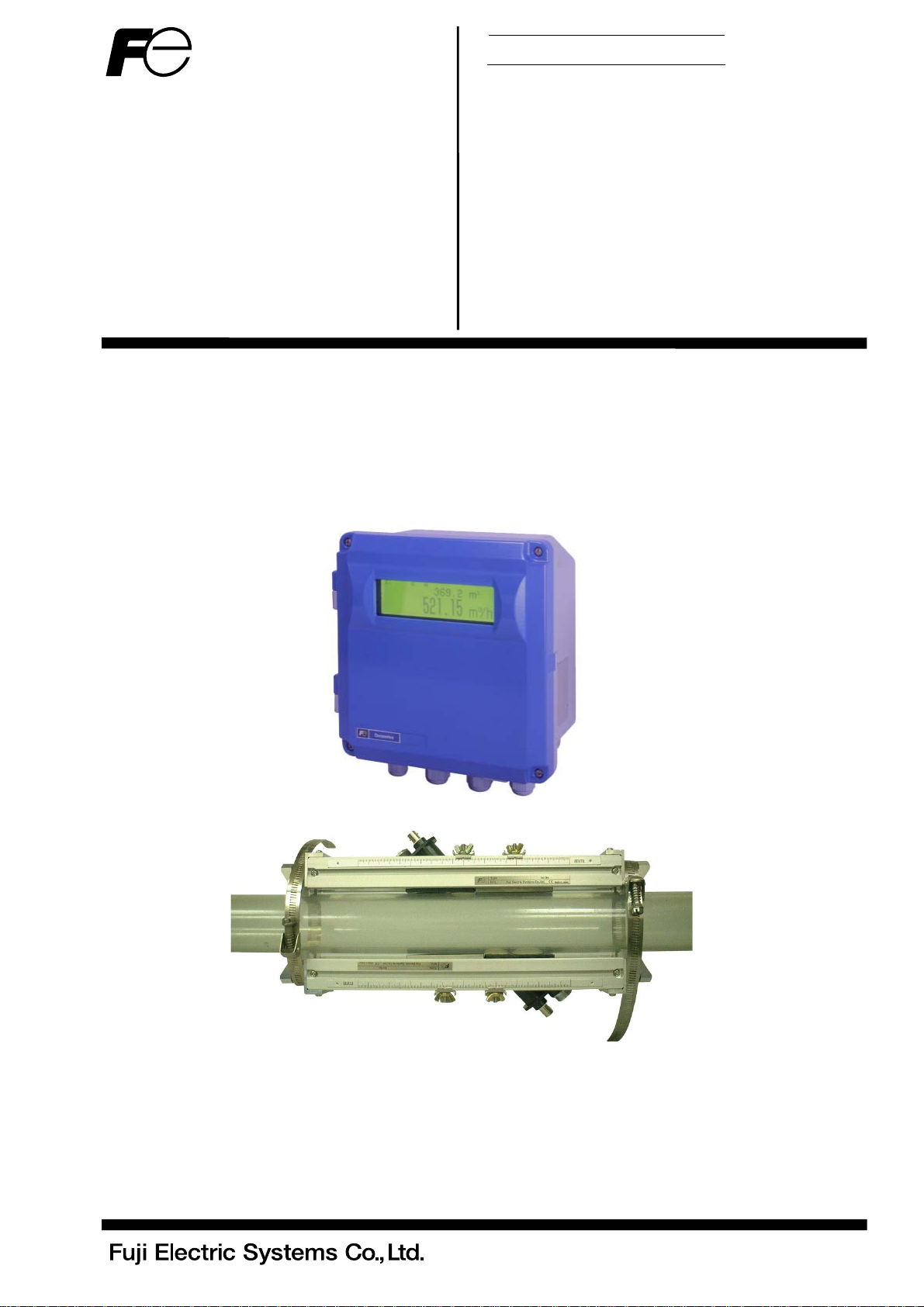
Instruction Manual
HYBRID
ULTRASONIC FLOWMETER
<Duosonics>
TYPE: FSH (Flow transmitter)
FSW (Detector)
FLY (Signal cable)
INF-TN1FSH-E
Page 2

PREFACE
We thank you very much for purchasing Fuji’s ultrasonic flowmeter.
The instruction manual concerns the installation, operation, checkup and maintenance of the Flow transmitter
(FSH) and Detector (FSW) of ultrasonic flowmeter. Read it carefully before operation.
Before using, be sure to read this instruction manual carefully to ensure correct installation, operation
•
and maintenance of the flowmeter. Note that incorrect handling may lead to trouble or personal injury.
The specifications of this flowmeter are subject to change for improvement without prior notice.
•
Do not attempt to modify the flowmeter without permission. Fuji is not responsible for any trouble
•
caused by modification without permission. If it becomes necessary to modify the flowmeter, contact
our office in advance.
This instruction manual should always be kept on hand by the operator.
•
After reading, be sure to keep this manual in a place where it can easily be seen by the operator.
•
Make sure that this manual is presented to the end user.
•
If the instruction manual has been lost, request another one (with charge) to our local business office.
•
Manufacturer: Fuji Electric Instrumentation Co., Ltd.
Type: Shown on nameplate of Flowmeter
Date of manufacture: Shown on nameplate of Flowmeter
Product nationality: Japan
• It is strictly prohibited to reproduce any part or the whole of this
instruction manual.
• The contents of this manual may be changed without prior
notice.
NOTICE
Issued in July 2005
Fuji Electric Systems Co., Ltd. 2005
INF-TN1FSH-E
- i -
Page 3
SAFETY PRECAUTION
Before using, read the following safety precaution to ensure correct handling of the flowmeter.
• The following items are important for safe operation and must be fully observed. These items are
classified into "DANGER" and "CAUTION".
Warning & Symbol Meaning
DANGER
CAUTION
• The items noted under "
• All the items are important and must be fully observed.
DANGER
CAUTION
Incorrect handling may lead to a risk of death or heavy injury.
Incorrect handling may lead to a risk of medium or light injury, or to a risk of
physical damage.
CAUTION
Caution on Installation and Piping
• This product has not an explosion-proof structure. Do not use it in a place
with explosive gases, otherwise, it can result in serious accidents such as
explosion, fire, etc.
• The unit should be installed in a place conforming with the installation
requirements noted in this instruction manual. Installation in an improper
location may lead to a risk of electric shocks, fire, malfunction, etc.
• The unit should be installed as noted in the manual. Improper installation
will cause falling, trouble or malfunction of the unit.
• During installation, make sure that the inside of the unit is free from cable
chips and other foreign objects to prevent fire, trouble, malfunction, etc.
• The items under "Caution on Installation" noted in the manual must be fully
observed. Careless installation may result in trouble or malfunction of the
unit.
" may also result in serious trouble depending on circumstances.
- ii -
INF-TN1FSH-E
Page 4
Caution on Wiring
• When performing wiring termination to prevent output trouble caused by
CAUTION
moisture, dew condensation or water leak, follow “Section 3.3. Flow
transmitter wiring” described in this manual
• Before performing the wiring work, be sure to turn OFF the main power to
prevent electric shocks.
• Do not perform wiring work outdoors in rainy days to prevent insulation
deterioration and dew condensation. Otherwise, it can result in trouble,
malfunction, etc.
• Be sure to connect a power source of correct rating. Connection of a
power source of incorrect rating may lead to a risk of fire.
• The unit must be earthed as specified to prevent electric shocks or
malfunction.
• The analog output signal cable should be wired as far away as possible
from high-voltage lines to prevent entry of noise signals as it will cause
malfunction of the unit.
• To prevent malfunction of the unit, the analog output signal cable and power
cable should be wired using separate conduits.
Caution on Maintenance/Inspection
• The unit should be inspected everyday to always obtain good results of
CAUTION
measurements.
• When measuring the insulation resistance between the power/output
terminal and the case, follow “Section 5.2.4. Measuring insulation
resistance” described in this manual.
• If the fuse is blown, detect and eliminate the cause, and then replace the
fuse with a spare. If there are no spares, replace the fuse with the one
specified in this manual (that must be prepared by customer). Use of a
fuse other than specified or its short-circuit may cause an electric shock or
fire. The fuse should be replaced according to “Section 5.3. Replacing
fuse” described in this manual.
INF-TN1FSH-E
- iii -
Page 5
CAUTION ON INSTALLATION LOCATION
CAUTION
(1) Sufficient space for daily inspection, wiring, etc.
(2) A place not exposed to direct sunshine or weathering.
(3) Isolation from vibration, dust and moisture
(4) A place not subjected to radiated heat from a heating furnace etc.
(5) A place not subjected to explosive gas and corrosive atmosphere
(6) A place not submerged
(7) A place remote from electrical devices (motor, transformer, etc.) which generate
electromagnetic induction noise, electrostatic noise, etc.
(8) A place not subjected to excessive fluid pulsation (pump discharge side)
(9) A place that provides enough place for the length of the str aight pipe.
(10) A place where ambie nt temperature and humidity are • 10 to +50°C and 90% RH or less for
flow transmitter (FSH), and •20 to +80°C and 100% RH or less for detector (FSW).
- iv -
INF-TN1FSH-E
Page 6

Contents
PREFACE.......................................................................................................................................................................... I
SAFETY PRECAUTION ................................................................................................................................................II
CAUTION ON INSTALLATION LOCATION........................................................................................................... IV
1. PRODUCT OUTLINE..................................................................................................................................................1
1.1. Outline......................................................................................................................................................................1
1.1.1. Measurement principle......................................................................................................................................1
1.2. Checking delivered items.........................................................................................................................................3
1.3. Checking type and specifications.............................................................................................................................4
1.4. Names of each part and functions ............................................................................................................................7
2. SELECTING INSTALLATION LOCATION ............................................................................................................8
2.1. Flow transmitter .......................................................................................................................................................8
2.2. Detector....................................................................................................................................................................9
2.2.1. Length of straight section of pipe....................................................................................................................10
2.2.2. Mounting position ........................................................................................................................................... 11
2.2.3. Mounting the sensor........................................................................................................................................12
3. INSTALLATION AND BEFORE START OF OPERATION.................................................................................13
3.1. Before operation.....................................................................................................................................................13
3.2. Installing the flow transmitter ................................................................................................................................14
3.3. Flow transmitter wiring..........................................................................................................................................15
3.3.1. Cautions in wiring...........................................................................................................................................15
3.3.2. Applicable wires..............................................................................................................................................15
3.3.3. Treatment of wiring port .................................................................................................................................15
3.3.4. Removing and mounting the shield plate........................................................................................................16
3.3.5. Wiring to each terminal...................................................................................................................................17
3.4. Setting piping parameters and calculating the spacing between sensor units.........................................................18
3.4.1. Selecting sensor type, mounting the sensor.....................................................................................................18
3.4.2. Entering piping specifications.........................................................................................................................20
3.5. Installing Detector..................................................................................................................................................22
3.5.1. Outline of detector installation procedure .......................................................................................................22
3.5.2. Treatment of mounting surface .......................................................................................................................22
3.5.3. Mounting the detector by Z method using the frame ......................................................................................22
3.5.4. Mounting the sensor unit by V method using a frame (1 measurement line)..................................................29
3.5.5. Mounting the sensor unit by Z method using a frame (2 measurement lines).................................................31
3.5.6. Mounting the sensor unit by V method using a frame (2 measurement lines) ................................................32
3.5.7. Mounting the sensor unit to a large-diameter pipe ..........................................................................................33
3.6. Setting analog output range and total pulse............................................................................................................36
3.6.1. Analog output range setting.............................................................................................................................36
3.6.2. Total pulse output setting ................................................................................................................................38
3.7. Zero adjustment......................................................................................................................................................40
4. SETTING PARAMETERS ........................................................................................................................................41
4.1. Description of display/setting unit .........................................................................................................................41
4.1.1. Description of display .....................................................................................................................................41
4.1.2. Description of keys .........................................................................................................................................41
4.2. Setting item list ......................................................................................................................................................43
4.3. Parameter specification table .................................................................................................................................44
4.4. Setting parameters..................................................................................................................................................47
4.4.1. Measurement method and sensor ....................................................................................................................49
4.4.2. Pipe specifications...........................................................................................................................................51
4.4.3. Measurement mode (Measurement mode, AO definition) ..............................................................................53
4.4.4. Output setting..................................................................................................................................................54
4.4.4.1. Range (range unit, range type, full scale, hysteresis) setting....................................................................54
4.4.4.2. Output limit..............................................................................................................................................57
4.4.4.3. How to set analog output at error (BURNOUT) ......................................................................................58
4.4.4.4. Rate limit..................................................................................................................................................59
4.4.5. Damping..........................................................................................................................................................60
4.4.6. Zero adjustment...............................................................................................................................................61
4.4.7. Display setting.................................................................................................................................................62
INF-TN1FSH-E
- v -
Page 7

4.4.8. Cut off............................................................................................................................................................. 63
4.4.9. Integration ...................................................................................................................................................... 64
4.4.9.1. Total unit.................................................................................................................................................. 64
4.4.9.2. Setting total pulse (Total rate, pulse width) ............................................................................................. 65
4.4.9.3. Total preset .............................................................................................................................................. 67
4.4.9.4. Total SW.................................................................................................................................................. 68
4.4.9.5. Determining how to dispose of total at error (BURNOUT) .................................................................... 69
4.4.10. Flow switch .................................................................................................................................................. 70
4.4.11. Status output ................................................................................................................................................. 71
4.4.12. Output calibration......................................................................................................................................... 73
4.4.13. Measurement unit......................................................................................................................................... 74
4.4.14. System language selection............................................................................................................................ 75
4.4.15. Setting serial communication (RS232C/RS485) .......................................................................................... 76
4.4.16. Maintenance ................................................................................................................................................. 77
4.4.16.1. Analog output adjustment and check..................................................................................................... 77
4.4.16.2. Checking status output .......................................................................................................................... 78
4.4.16.3. Calibrating temperature sensor.............................................................................................................. 79
4.4.16.4. Checking temperature sensor................................................................................................................. 80
4.4.16.5. Test mode............................................................................................................................................... 81
4.4.17. LCD backlight.............................................................................................................................................. 82
4.4.18. Key lock ....................................................................................................................................................... 83
4.4.19. Checking system name................................................................................................................................. 84
4.4.20. Details of measurement................................................................................................................................ 85
4.4.20.1. Transit time............................................................................................................................................ 85
4.4.20.2. Pulse Doppler ........................................................................................................................................ 88
4.4.20.3. Initializing setting parameters ............................................................................................................... 92
4.4.20.4. Confirmation of software version.......................................................................................................... 92
5. MAINTENANCE AND INSPECTION .................................................................................................................... 93
5.1. Daily inspection..................................................................................................................................................... 93
5.2. Periodic inspection ................................................................................................................................................ 93
5.2.1. Checking zero point........................................................................................................................................ 93
5.2.2. Calibrating current output circuit ................................................................................................................... 93
5.2.3. Calibrating temperature sensor circuit............................................................................................................ 93
5.2.4. Measuring insulation resistance...................................................................................................................... 94
5.3. Replacing fuse....................................................................................................................................................... 95
5.4. Replacing relay...................................................................................................................................................... 96
5.5. Replacing LCD...................................................................................................................................................... 97
6. TROUBLESHOOTING............................................................................................................................................. 98
6.1. How to confirm normal operation......................................................................................................................... 98
6.1.1. Checking on LCD........................................................................................................................................... 98
6.1.2. Checking measurement status information..................................................................................................... 99
6.1.2.1. Define “RAS”.......................................................................................................................................... 99
6.1.2.2. Status information ................................................................................................................................. 101
6.1.2.3. Measurement data information.............................................................................................................. 102
6.2. Faults and remedies............................................................................................................................................. 104
6.2.1. Display error................................................................................................................................................. 104
6.2.2. Key failure.................................................................................................................................................... 104
6.2.3. Measurement value error.............................................................................................................................. 105
6.2.4. Analog output error ...................................................................................................................................... 107
6.3. Checking received waveform.............................................................................................................................. 108
6.3.1. Method by oscilloscope................................................................................................................................ 108
6.3.2. Checking signal waveform (TRANSIT TIME)............................................................................................ 109
6.3.3. Checking demodulated waves (Pulse Doppler) .............................................................................................111
6.3.4. Measures against hardware failure ................................................................................................................111
7. PC LOADER SOFTWARE ......................................................................................................................................112
7.1. Copyright of this software....................................................................................................................................112
7.2. Outline..................................................................................................................................................................112
7.3. PC to be used........................................................................................................................................................112
7.3.1. Computer.......................................................................................................................................................112
7.3.2. Memory capacity...........................................................................................................................................112
7.3.3. Interface.........................................................................................................................................................112
7.3.4. OS..................................................................................................................................................................112
- vi -
INF-TN1FSH-E
Page 8

7.4. Installing of Software........................................................................................................................................... 113
7.5. Startup Method.....................................................................................................................................................116
7.5.1. Communications ...........................................................................................................................................117
7.5.2. Setting ...........................................................................................................................................................118
7.5.2.1. Save setting ............................................................................................................................................118
7.5.2.2. Read setting............................................................................................................................................ 118
7.5.3. Version ..........................................................................................................................................................119
7.6. Structure of Function............................................................................................................................................119
7.7. Establish Setting...................................................................................................................................................120
7.8. Range Setting .......................................................................................................................................................122
7.9. Total Setting .........................................................................................................................................................124
7.10. Status Output Setting..........................................................................................................................................126
7.11. Display Setting...................................................................................................................................................127
7.12. System Setting....................................................................................................................................................128
7.13. Measurement......................................................................................................................................................129
7.14. Pulse Doppler Measurement ..............................................................................................................................130
7.14.1. Detailed setting (optional function).............................................................................................................130
7.14.2. Flow velocity profile (optional function) ....................................................................................................132
7.14.3. Operation Information.................................................................................................................................134
7.15. Transit Time Difference Measurement...............................................................................................................136
7.15.1. Detailed Setting (optional function) ............................................................................................................136
7.15.2. Received Signal (optional function)............................................................................................................138
7.15.3. Operation Information.................................................................................................................................139
7.16. Maintenance.......................................................................................................................................................141
7.17. End .....................................................................................................................................................................143
7.18. Uninstalling of Software ....................................................................................................................................143
8. APPENDIX ................................................................................................................................................................144
8.1. External communication specifications................................................................................................................144
8.1.1. Communication specifications......................................................................................................................144
8.1.2. Message configuration ..................................................................................................................................144
8.1.2.1. Receiving ...............................................................................................................................................144
8.1.2.2. Response ................................................................................................................................................144
8.1.2.3. Error response ........................................................................................................................................145
8.1.3. Error check....................................................................................................................................................145
8.1.4. Function code table .......................................................................................................................................146
8.1.5. Error code table.............................................................................................................................................147
8.1.6. Cable connection specifications (RS-232C)..................................................................................................147
8.2. Specifications.......................................................................................................................................................148
8.3. Outline diagram....................................................................................................................................................150
8.4. Items to be specified at placement of an order .....................................................................................................154
8.5. Composition of key operation..............................................................................................................................157
8.6. Piping data ...........................................................................................................................................................164
8.7. Making gauge paper.............................................................................................................................................172
INF-TN1FSH-E
- vii -
Page 9
1. PRODUCT OUTLINE
1.1. Outline
This high precision flowmeter is the world’s first clamp-on type ultrasonic flowmeter that adopts the pulse Doppler
method and the transit time method as its measurement principles. The ultrasonic flowmeter for industrial use
employs the pulse Doppler method, which directly measures flow distribution, thus easing straight pipe conditions and
allowing measurement of flows that have not grown into eddy or laminar flow. Combined use of the transit time
method allows the hybrid ultrasonic flowmeter to be used for measuring a significantly wide range of liquids. The
pulse Doppler method, which uses echoes coming from reflectors in a liquid to be measured, is ideal for the
measurement of liquids that contain air bubbles and particles. On the other hand, the transit time method, which
allows ultrasonic waves to pass through for measurement, is ideal for the measurement of clean liquids.
The new hybrid technique employing both the pulse Doppler and the transit time methods allows the flowmeter to be
used for wider range of applications. In addition, our self-developed switching algorithm ensures automatic switching
between the two methods depending on the conditions of a liquid to be measured (such as mixing status of air bubbles
or particles and flow rate), thus facilitating measurement.
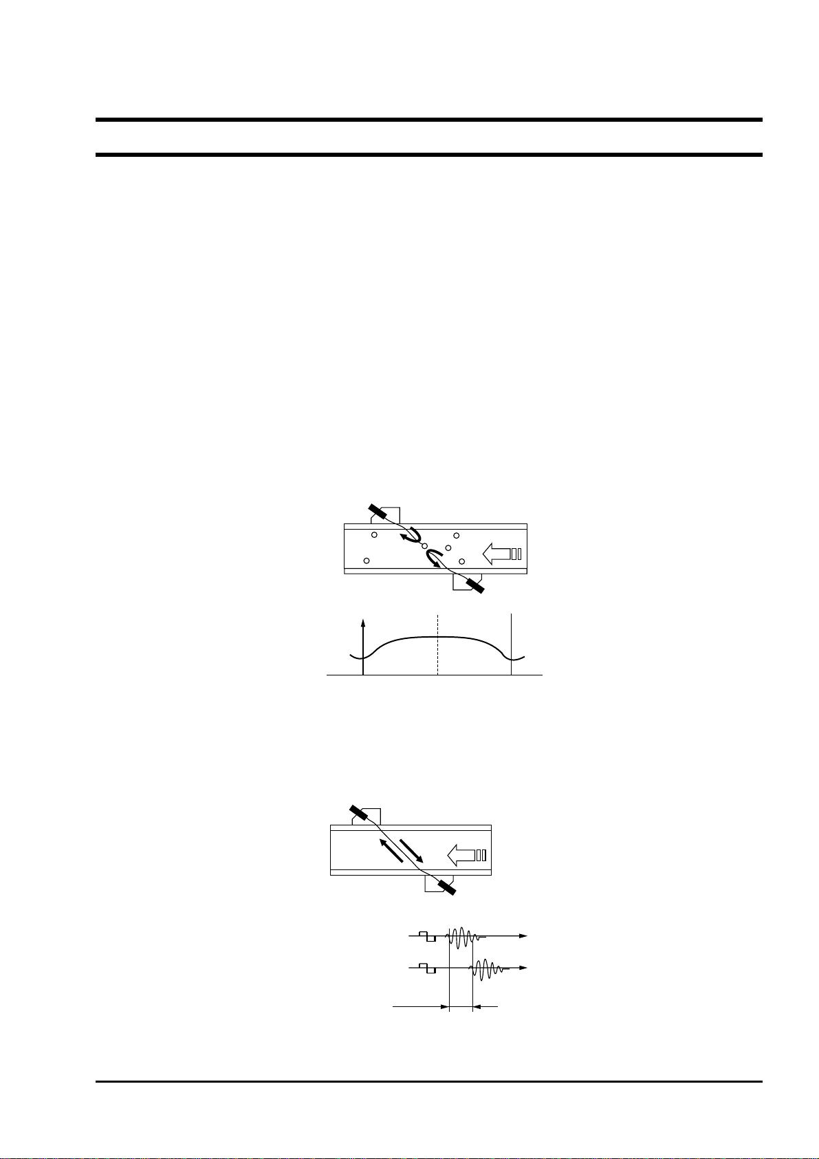
1.1.1. Measurement principle
<Pulse Doppler method>
The pulse Doppler method measures flow distribution and flow rate based on the fact that Doppler frequency of the
•
echo coming from reflectors such as air bubbles and particles in liquids changes with fluctuation of flow rate.
Sensor 2
Air bubble
Reflection
Flow velocity
distribution 2
Flow rate
Pipe wall Center Pipe wall
Flow velocity
distribution 1
Flow
Sensor 1
<Transit time method>
Under the transit time method, ultrasonic pulses are propagated slanted from both upstream and downstream sides,
•
and time difference of flows are detected to measure the flow rate.
Sensor 2
Flow
Sensor 1
Send Receive
Sensor 1 J 2
INF-TN1FSH-E
Sensor 2 J 1
Time difference ∆T
- 1 -
Page 10
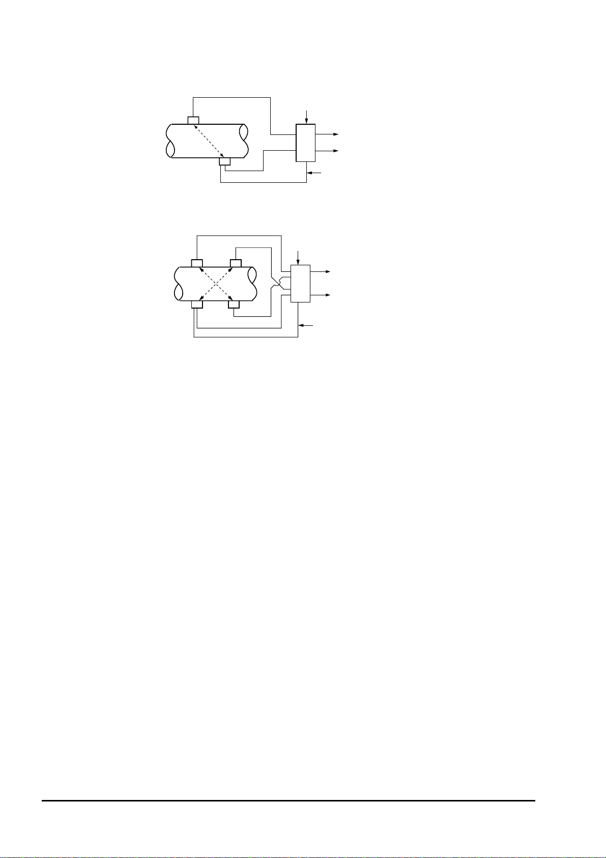
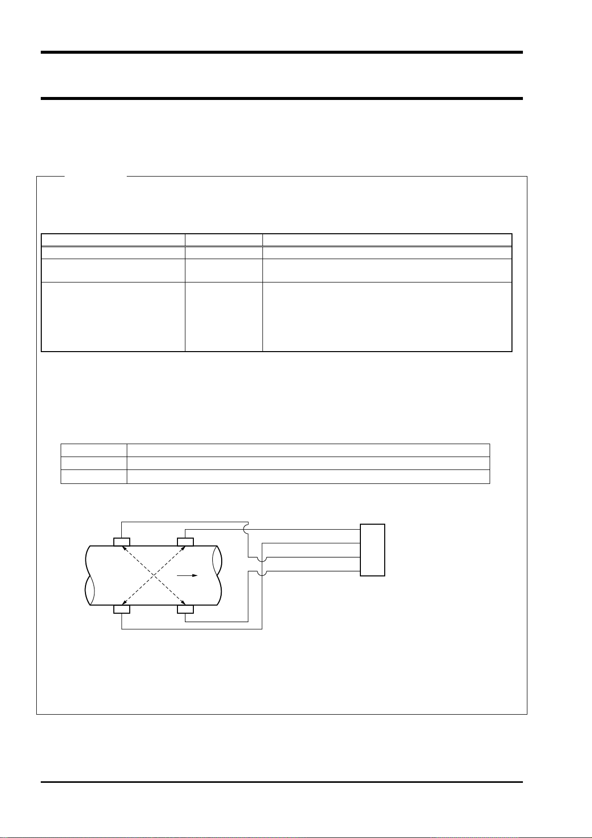
Configuration
(1) 1 measurement line method (Z method)
Detector
(2) 2 measurement line method (Z method)
Detector
Cable
Cable
Power supply
4 to 20 mA DC
Contact (3 points max.)
Flow
transmitter
Temperature sensor cable
Power
supply
4 to 20 mA DC
Flow
Contact (3 points max.)
transmitter
Temperature sensor cable
- 2 -
INF-TN1FSH-E
Page 11
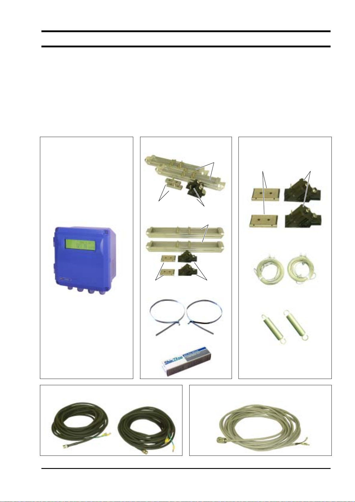
1.2. Checking delivered items
Flow transmitter (FSH)
Flow transmitter main unit ··································1 set
Waterproof gland (Built into the main unit)·········1 set
Wall mount fittings (Built into the main unit)······1 set
Detector (FSWS12, 21, 40)
Detector main unit (FSWS12, 21) ·······················1 set
Detector main unit (FSWS40) ·····························1 set
Absorber unit ······················································1 set
Stainless steel belt ···············································1 set
Fittings ································································1 set
Silicon rubber······················································ 1 pc
Detector (FSWS50)
Detector main unit (FSWS50)····························· 1 set
Absorber unit······················································ 1 set
Wire rope···························································· 1 set
Spring for mounting············································ 1 set
Signal cable (FLY6)
Cable for ultrasonic signals··················· 1 pair (2 pcs.)
Signal cable (FLY7)
Cable for temperature sensor ··································· 1
CD-ROM (Instruction manual and Loader software)
······································ 1
Flow transmitter (FSH) Detector (FSWS12, 21, 40) Detector (FSWS50)
Detector (FSWS12, 21)
Frame
Absorber unit Sensor unit
Absorber unit
Detector (FSWS40)
Sensor unit
Frame
Wire rope
Absorber unit
Sensor unit
Stainless steel belt
Spring for mounting
Silicon rubber
Signal cable (FLY6)
Cable for ultrasonic signals
Signal cable (FLY7)
Cable for temperature sensor
INF-TN1FSH-E
- 3 -
Page 12
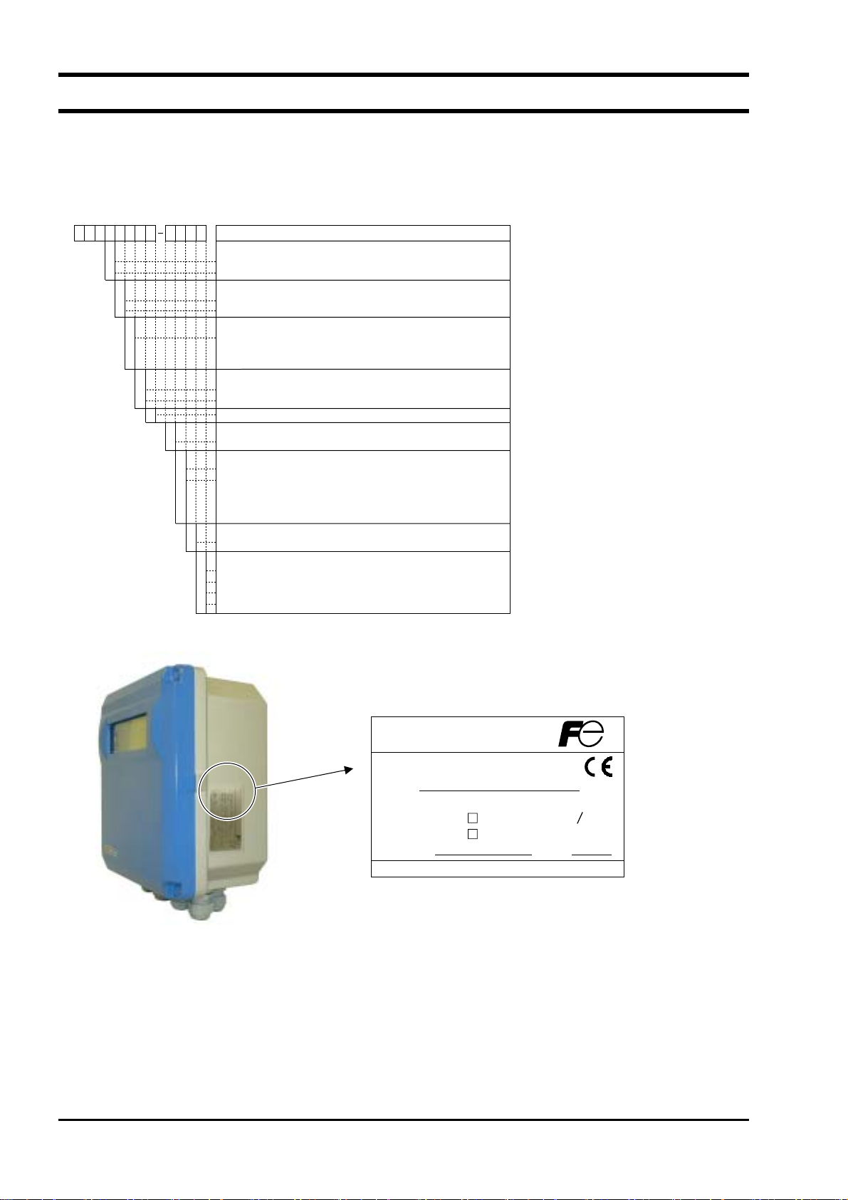
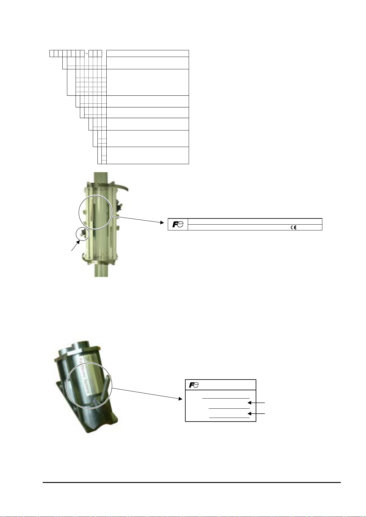
1.3. Checking type and specifications
The specification plates attached to the flow transmitter and the detector list the type and specifications of the product.
Check that they represent the type you ordered, referring to the following code symbols.
< Flow transmitter (FSH)>
12345678 9101112
F
SH
1S
S
E
Y
A
Y
1
4
1
S
Y
A
Type (4th digit)
Standard (Japanese)
Standard (English)
Velocity profile output (5th digit)
None
Available
Use (6th digit)
Single path or Changeover two-path (Note)
Note: 2 sets of detectors and coaxial cables (FLY6)
needed for two-path system
Power supply (7th digit)
100 to 240VAC, 50/60Hz
20 to 30VDC
Modification No. (8th digit)
Case structure (9th digit)
Watertight type (IP67)
Conduit connection (10th digits)
[G1/2 and G3/8 (female screw)] with waterproof gland
[G1/2 (female screw)] with union gland (for plica)
Note: The wiring port for coaxial cable (for ultrasonic
sensor) and 3-wire cable (for temperature
sensor) is provided with waterproof gland [G3/8 (female screw)].
For use with explosion-proof detector (11th digit)
None
Y
Parameter setting, Tag plate (12th digit)
None
Y
With setting
A
With setting + Tag plate
B
Tag plate
C
Description
Ultrasonic Flow Meter
Type
Output DC4-20mA
Power Supply AC100-240V 50 60Hz
DC20-30V
Ser.No.
Fuji Electric Systems Co.,Ltd.
Mfd.
Made in Japan
- 4 -
INF-TN1FSH-E
Page 13
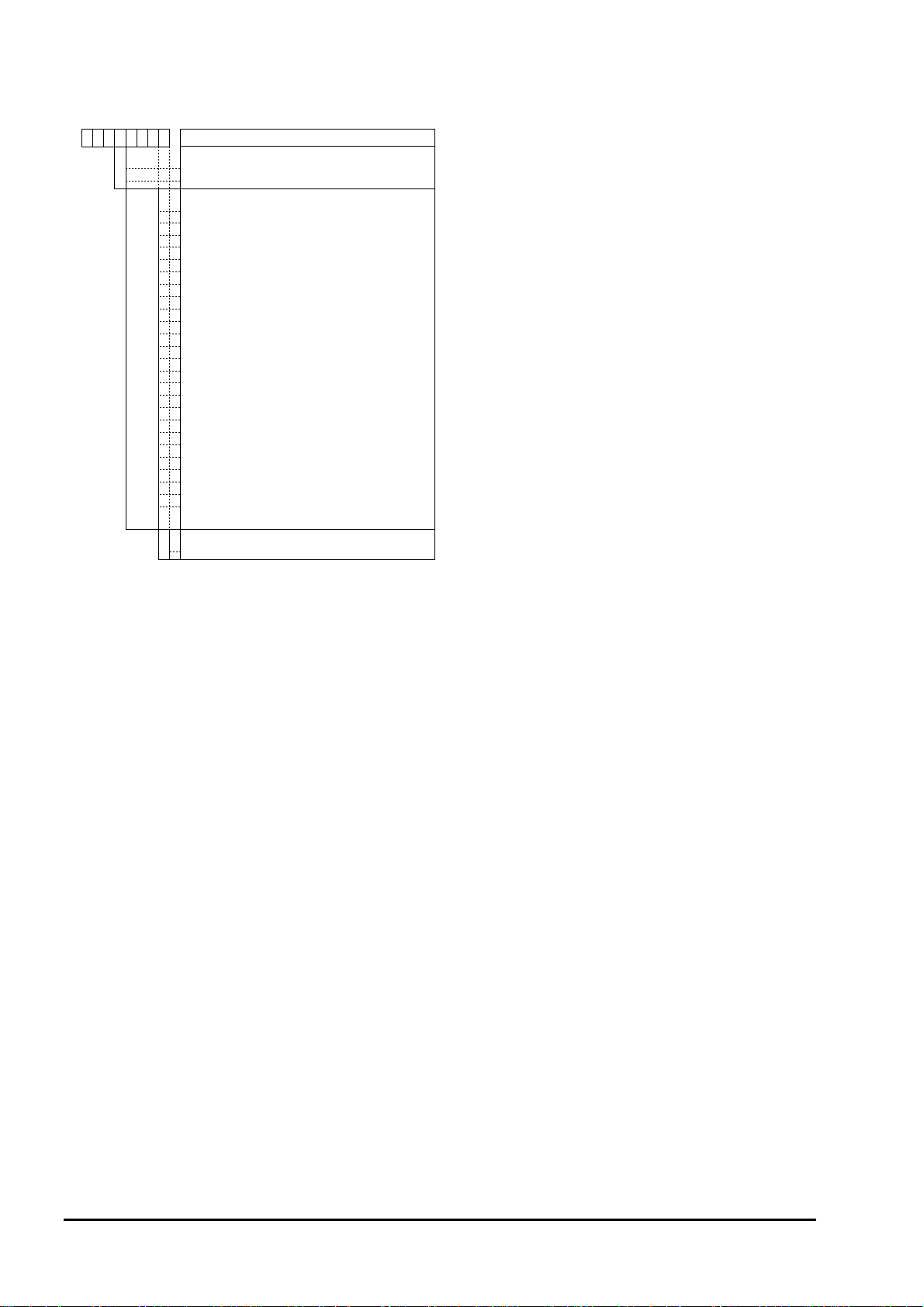
<Detector (FSW)>
12345678 910
F
S
W
1
S
1
2
2
1
4
0
5
0
0
1
Y
11
Description
Type (4th digit)
Standard
Kind of detector (5th and 6th digit)
Small diameter detector (φ 50 to 100 mm)
Small size detector (φ 100 to 200 mm)
Middle size detector (φ 200 to 500 mm)
Large size detector (φ 500 to 1000 mm)
Use (7th digit)
Watertight type (IP67)
Modification No. (8th digit)
Mark 1
Signal cable (9th digit)
None
Acoustic coupler (10th digit)
Y
None
Silicone compound
A
Option (11th digit)
None
Y
Tag Plate
A
Type.
Mfd.
Fuji Electric Systems Co.,Ltd.
Ser.No.
Made in Japan
Sensor unit
Note: To use the flowmeter employing the transit time method only, a detector (FLW) and a flow transmitter (FSH)
must be used in combination. See data sheet EDS6-71 or EDS6-111 for details of selection of the detector
(FLW) and dedicated cables (FLY1, FLY2).
<Sensor unit>
The numeric value marked on the DF field of the nameplate of the sensor unit represents the sensor constant, which
is determined by actual current calibration performed as part of the delivery test at the factory.
Ultrasonic Flow Meter
SN :
DF
-
P :
DF-M :
Sensor constant for plastic pipe
Sensor constant for metal pipe
Note: Use a detector (FLW) and a transmitter (FSH) in combination to use the instrument by transit time method
only. Refer to data sheet EDS6-71 or EDS6-111 for details of selection of the detector (FLW) and
dedicated cables (FLY1, FLY2).
INF-TN1FSH-E
- 5 -
Page 14
<Signal cable (FLY)>
12345678
F
LY
1
6
7
0
0
1
0
1
0
2
0
2
0
3
0
3
0
4
0
4
0
5
0
5
0
6
0
6
0
7
0
7
0
8
0
8
0
9
0
9
0
0
1
1
1
2
1
3
1
4
1
5
1
Kind of cable (4th digit)
Coaxial cable (for ultrasonic sensors) 1 pair (2 pcs.)
Three-core cable (for temperature sonsor)
Cable length (5th to 7th digit)
5
5m
0
10m
5
15m
0
20m
5
25m
0
30m
5
35m
0
40m
5
45m
0
50m
5
55m
0
60m
5
65m
0
70m
5
75m
0
80m
5
85m
0
90m
5
95m
0
100m
0
110m
0
120m
0
130m
0
140m
0
150m
Description
Modification No. (8th digit)
Mark1
1
- 6 -
INF-TN1FSH-E
Page 15
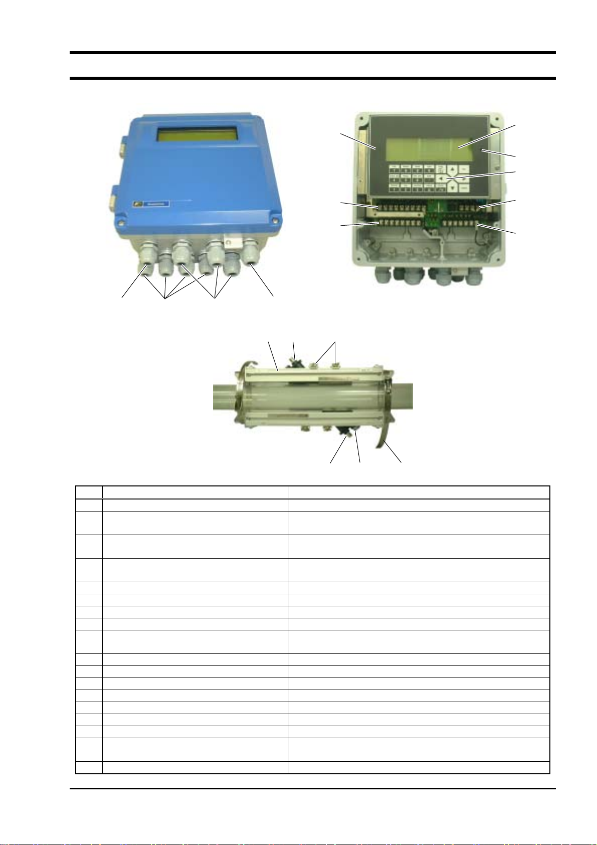
1.4. Names of each part and functions
(5)
(9)
(10)
(6)
(12)
(7)
(8)
(11)
(3) (2) (4) (1)
(15) (14) (13)
(16) (17) (18)
No. Name Description
(1)
Wiring connection port for power cable Wiring port for power cable
(2)
Wiring connection port for ultrasonic signal
Wiring port for ultrasonic signal cable
cable
(3)
Wiring connection port for temperature
Wiring port for temperature sensor cable
sensor cable
(4)
Wiring connection port for DO output
Wiring port for for DO output cable
cable
(5)
Display and setting unit Displays flow rate, etc. Used for various setting operations.
(6)
LCD Displays flow rate and various settings.
(7)
Setting key Used for making settings.
(8)
Power terminal Connect power cable to this terminal.
(9)
I/O terminal Connect power output cable, communication cable, and
temperature sensor cable to this terminal.
(10)
Input terminal Connect ultrasonic signal cable to this terminal.
(11)
Output terminal Connect Do output cable to this teminal.
(12)
LCD contrast adjusting knob Used for adjusting the contrast of the LCD.
(13)
Sensor unit Used for transmitting/receiving ultrasonic waves.
(14)
Sensor frame Used for fastening the sensor unit to the piping.
(15)
Unit arm Used for fastening the sensor by pressing it against the piping.
(16)
BNC connector for ultrasonic signal cable Transmits ultrasonic send/receive signals.
(17)
Water-tight connector for temperature
Transmits temperature sensor signals.
sensor cable
(18)
Stainless steel belt Used for fastening the sensor frame to the piping.
INF-TN1FSH-E
- 7 -
Page 16
2. SELECTING INSTALLATION LOCATION
Select an installation location that satisfies the following conditions, with ease of maintenance and inspection, service
life of the instrument, and assurance of reliability taken into consideration.
CAUTION
(1) A place where ambient temperature and humidity are as follows:
Flow transmitter (FSH): −10 to +50°C, 90%RH or lower
Detector (FSW): −20 to +80°C, 100%RH or lower
(2) A place not subject to direct sunlight or weather
(3) A place provided with space for daily inspection and wiring work
(4) A place not subject to radiant heat from a heating furnace, etc.
(5) A place not in an atmosphere of corrosive or explosive gas
(6) A place not subject to flooding
(7) A place not subject to vibration, dust, or moisture
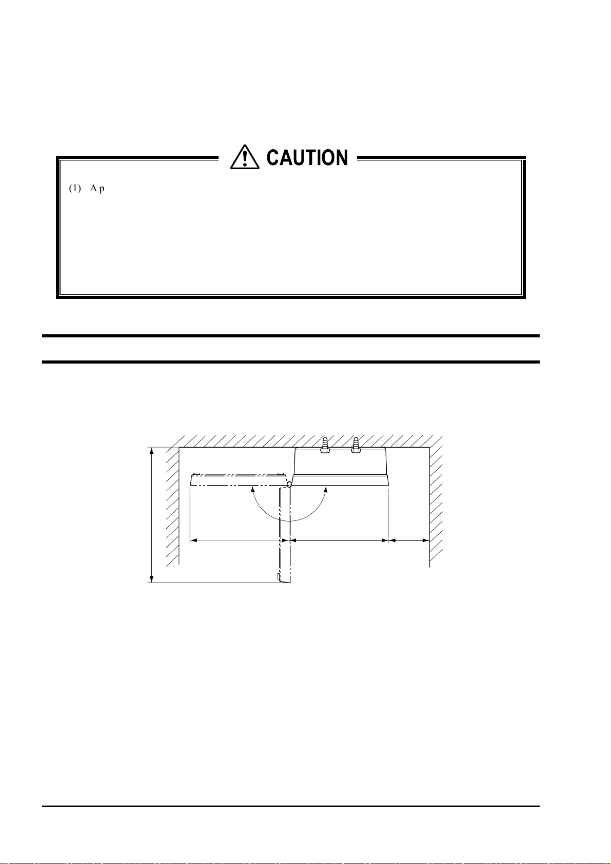
2.1. Flow transmitter
Allow space of 100 mm or more between the flow transmitter and the surrounding walls. Allow sufficient space for
opening of the front cover for maintenance.
Allow sufficient space for wiring at the bottom of the case.
N
E
P
O
348mm
245mm
244mm 100mm
or more
- 8 -
INF-TN1FSH-E
Page 17
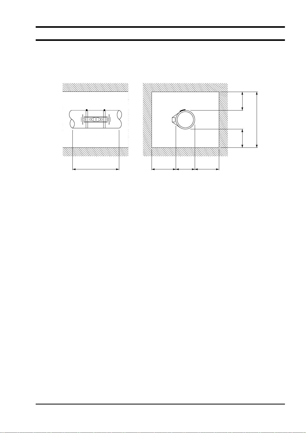
2.2. Detector
The mounting position of the detector, in other words, the state of the piping where the flow rate is to be measured,
affects the accuracy of measurement to a great extent. Select a place that satisfies the conditions described in 2.2.1.
Length of straight section of pipe. Assure sufficient working space for installation and maintenance, referring to the
figures shown below.
200
or more
200 or more
Note
200
or more
D + 1200 or more
600
or more
D
600
or more
D: Pipe diameter
Space required for mounting of detector
INF-TN1FSH-E
- 9 -
Page 18
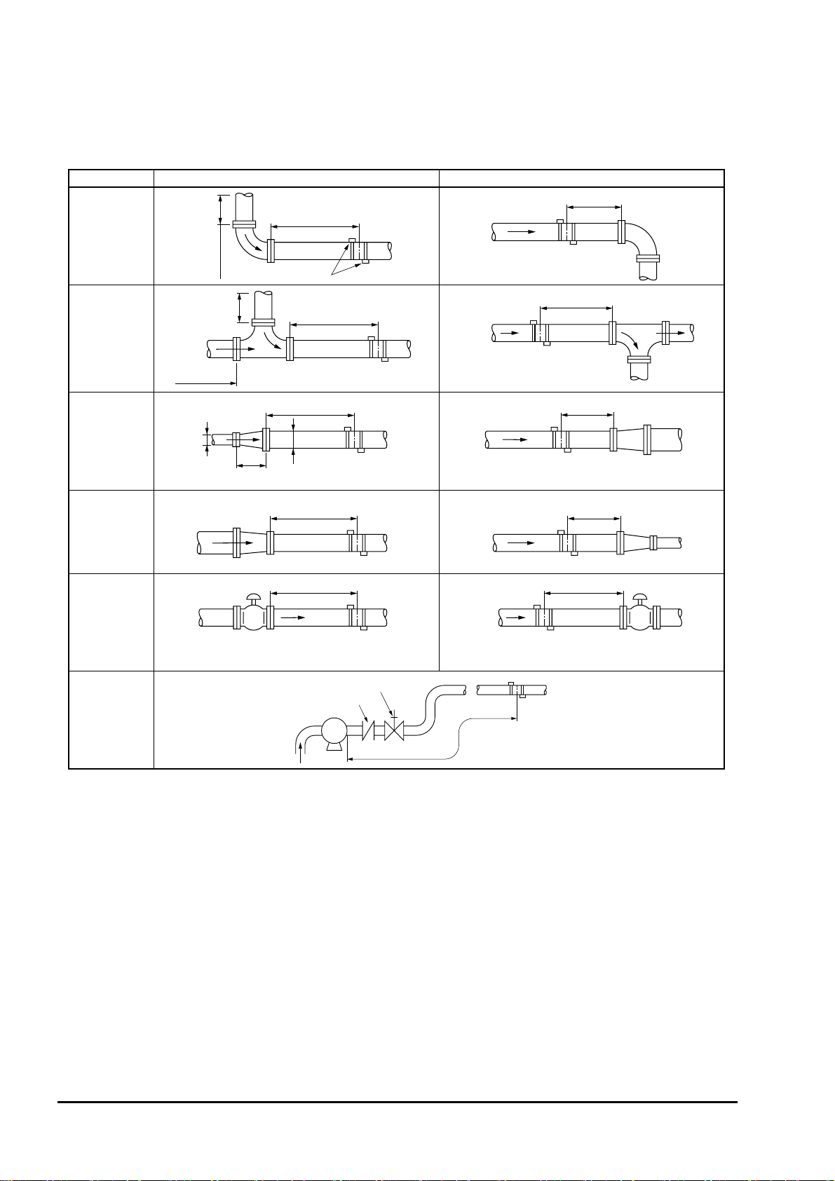
2.2.1. Length of straight section of pipe
To assure the accuracy of flow rate measurement, allow sufficient length of the straight section of the pipe on the
upper/lower stream side, referring to “straight pipe conditions” shown below.
Classification Upstream side Downstream side
L≧10D
90 bend
( D : Inside diameter of pipe)
L≧5D
Tee
Diffuser
Reducer
Various Valve
Pump
10D or more
or
10D
more
10D or more
or
0.5D
more
≧1.5D
In case that flow control valve exists on
upstream side.
Detector
L≧50D
L≧30D
D
L≧10D
L≧30D
Check valve
P
L≧10D
L≧5D
L≧5D
L≧10D
In case that flow control valve exists on
downstream side.
Stop valve
L≧50D
(Note) The source : JEMIS-032
- 10 -
INF-TN1FSH-E
Page 19
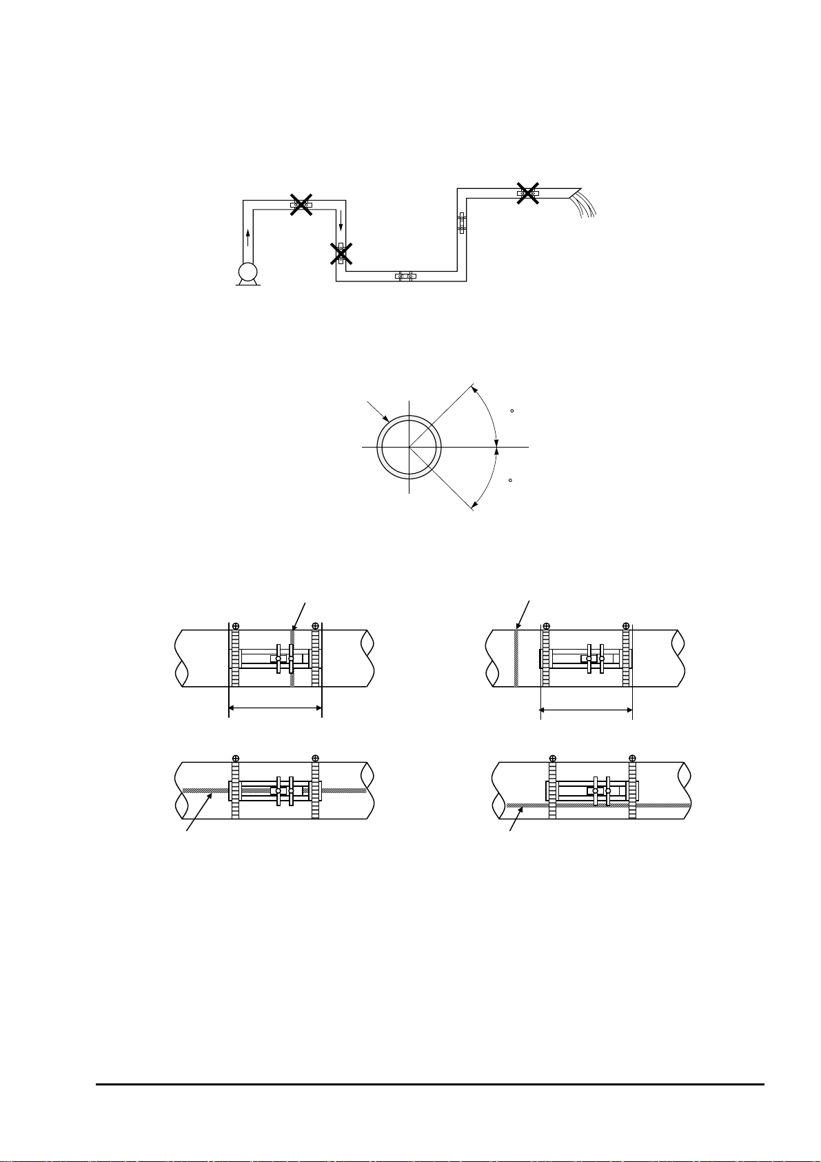
2.2.2. Mounting position
The instrument can be mounted horizontally or in any other position. However, pay attention to the following.
(1) Allow fluid to fill the pipe and keep it flowing at all times.
Air tends to pile up.
The pipe
may not be
filled with fluid.
The pipe may not be filled with fluid.
Good
Pipe
Good
45
45
Welded part
○
Does not include welded part.
○
Pump
(2) Mount the flowmeter within ±45° from the center plane in the case of horizontal pipe run.
Mount it at an arbitrary position on the outer periphery in the case of vertical pipe run.
Horizon
(3) Avoid mounting the flowmeter in a position where the pipe is deformed, or on a flange or welded part.
Overlaid on welded part. Not overlaid on welded part.
Includes welded part.
×
Welded part
INF-TN1FSH-E
- 11 -
Page 20
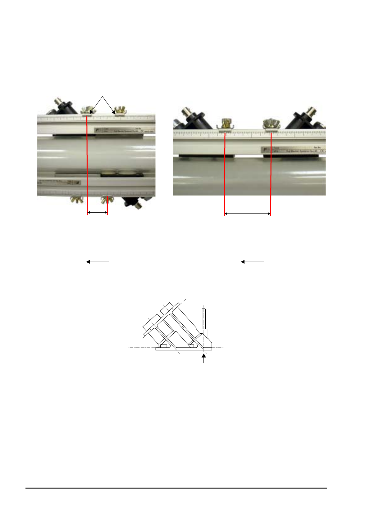
2.2.3. Mounting the sensor
The detector can be mounted either by Z method or V method as shown by Fig. 1.
The top surface of the sensor is referenced as shown by Fig. 2. Mount a pair of sensors, allowing the specified spacing
between the surfaces of both sensors.
Sensor R
on downstream side
(without temperature
sensor)
[Z method] [V method]
Cursor
Sensor R
on downstream side
Sensor F
on upstream side
Sensor F on upstream side
(with temperature sensor)
Sensor mounting spacing
Sensor mounting spacing
Flow direction
Flow direction
Fig. 1 Mounting of sensor
Reference
Fig. 2 Reference surface of sensor
Mount the sensor by Z method in the case of hybrid measurement system.
Mount it by Z method to take measurements under the following conditions by transit time method only.
To measure high turbidity fluids such as sewage influent
•
When the pipe is provided with mortar lining
•
When the pipe is old and thick scale is considered to have attached within the pipe
•
- 12 -
INF-TN1FSH-E
Page 21
3. INSTALLATION AND BEFORE START OF
OPERATION
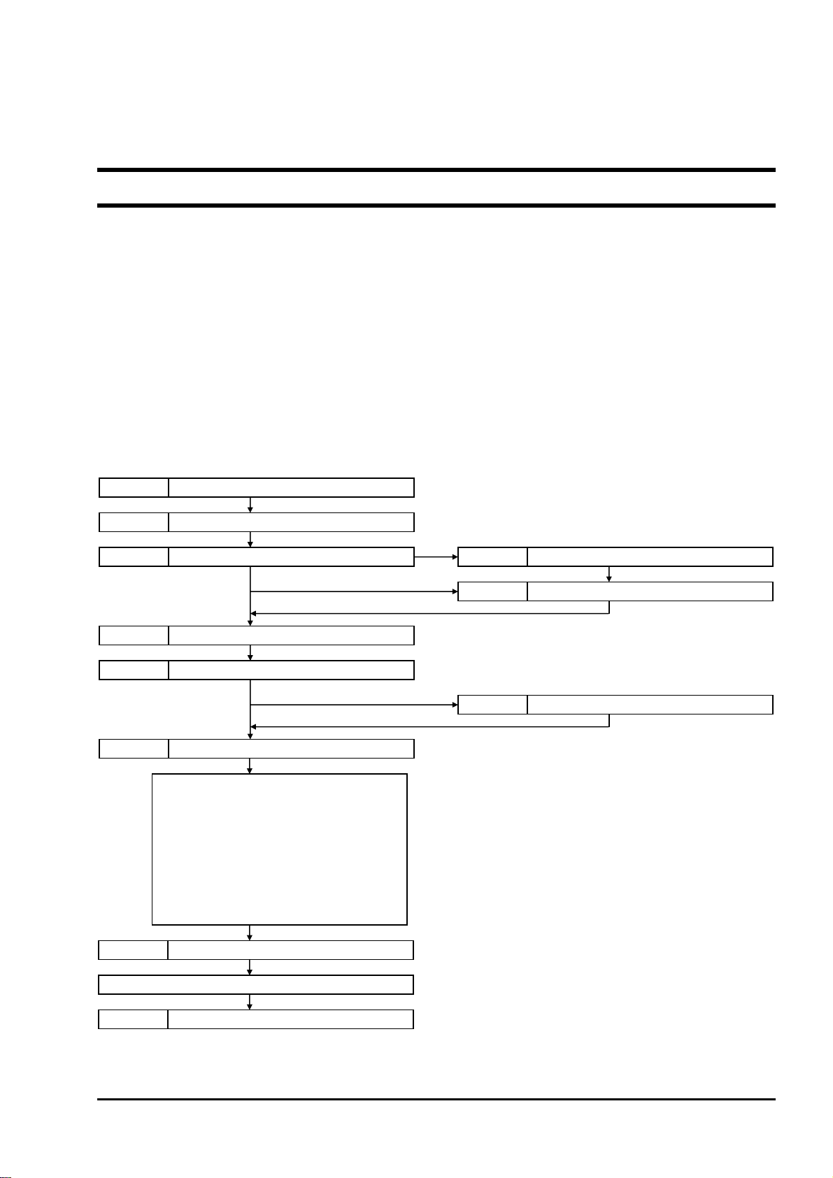
3.1. Before operation
(1) Selection of installation location of flow transmitter and detector
(2) Installation and wiring of flow transmitter
(3) Power ON
Check the power supply specifications and wiring before turning on the power.
(4) Entering of piping parameters and calculation of the spacing between the sensor units (*Check the spacing of
sensor units if parameter setting is provided.)
(5) Mounting of frame to measurement piping (*When using a frame for mounting)
(6) Mounting of sensor unit
Be careful not to mount the unit with wrong dimension.
(7) Setting of measurement range (*Not required if measurement range is specified by parameter setting provided.)
(8) Zero point adjustment
Before performing zero point adjustment, check that the pipe is filled with fluid, the fluid is in still state, and that
the measurement status is normal.
(9) Start of measurement
3.3. Flow transmitter wiring
3.1. Before operation
3.4.2. Entering piping specifications 4.4.1. Measurement method and sensor
3.5. Installing detector
6.3. Checking received waveform
3.7. Zero adjustment
8.5. Composition of key operation
Chapter 5. MAINTENANCE AND INSPECTION
Output specification setting
System setting
Total specification setting
Total alarm setting
Measurement display specification setting
Dumping setting
Low flow rate cut setting
Output correction setting
Status output setting
Measurement
3.4.2. Entering piping specifications
Chapter 6. TROUBLESHOOTING
INF-TN1FSH-E
- 13 -
Page 22
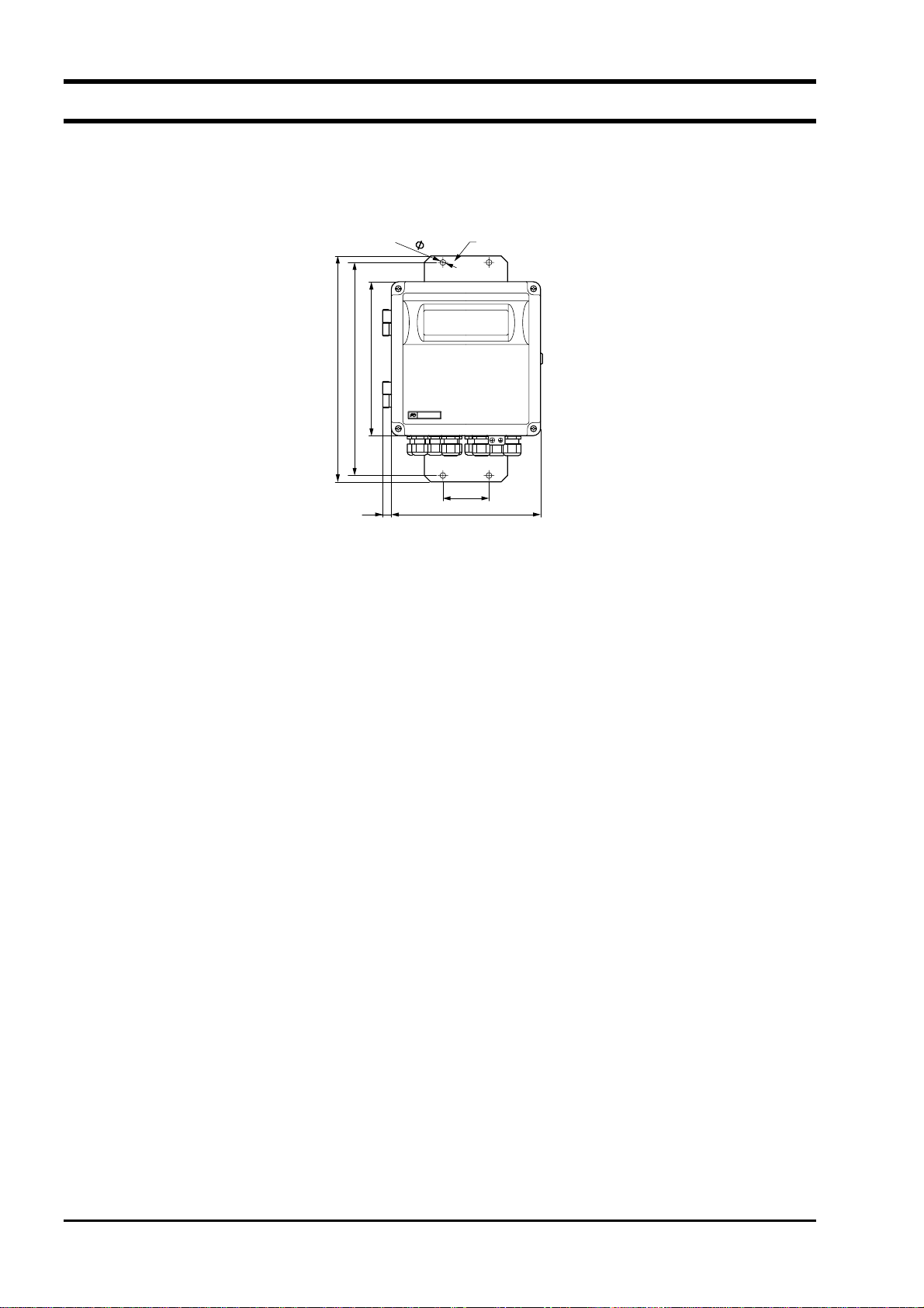
3.2. Installing the flow transmitter
The flow transmitter can be mounted on a wall or on a panel.
Use four M8 bolts to mount the flow transmitter on a wall or a panel. Drill holes according to the mounting hole
dimensions shown below, and fasten the flow transmitter using the M8 bolts.
352
332
14
240
4-
9
Duosonics
Mounting plate
72
233
- 14 -
INF-TN1FSH-E
Page 23
3.3. Flow transmitter wiring
3.3.1. Cautions in wiring
CAUTION
(1) Use a dedicated cable (FLY) as a signal cable between the detector (FSW) and the flow transmitter
(FSH). Do not join cable in the middle.
(2) Be sure to let the signal cables installed between the detector and the flow transmitter run through a
metal conduit tube. The signal cables for upper and the lower streams can be made to run through
the conduit tube together. However, do not let the power cable run through the conduit tube
together with the signal cables to avoid induction problems.
(3) Use shielded cables for output signals as far as possible.
(4) To prevent noise from coming in, avoid installing wiring in a duct together with the power cable.
(5) Directly ground the power cable that includes a ground lead.
(6) The flowmeter is not equipped with a power switch. Mount one separately.
(7) Tightly seal the unused wiring ports with supplied sealing caps.
3.3.2. Applicable wires
Use the following cables.
Power cable:
•
3-wire or 2-wire cabtyre cable
Nominal sectional area: 0.75 mm
Finished outer diameter: φ11 mm
Output signal cable:
•
2-wire or multi-wire cabtyre cable as required
Finished outer diameter: φ11 mm
Cable between detector and flow transmitter:
•
Cable for ultrasonic wave signals (High-frequency coaxial double shield cable with characteristic impedance
of 50 Ω, With waterproof BNC connector provided on one side)
Finished outer diameter: φ7.3 mm
Cable for temperature sensor (3-wire shielded cable, With waterproof connector provided on one side)
Finished outer diameter: φ6.9 mm
2
or more
3.3.3. Treatment of wiring port
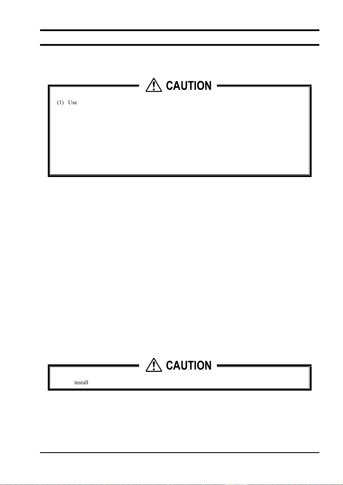
The casing of the flow transmitter is of watertight type (IP67). However, to prevent entry of moisture and occurrence
of condensation, airtight processing of wiring ports is required. Be sure to take measures against entry of water using
the waterproof glands supplied with the instrument. Tightly seal unused glands using the supplied sealing caps.
CAUTION
Do not install the flow transmitter in a place subject to the occurrence of flooding.
INF-TN1FSH-E
- 15 -
Page 24
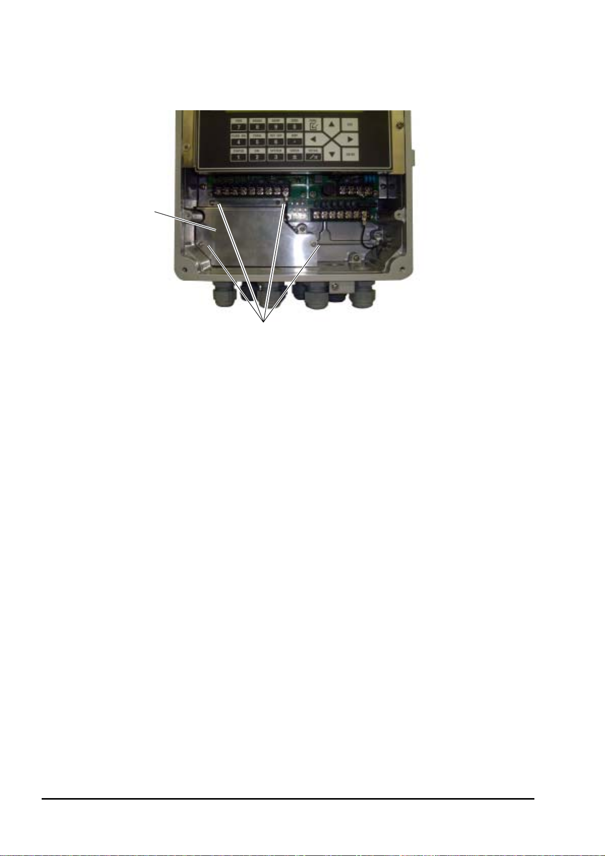
3.3.4. Removing and mounting the shield plate
Before installing wiring, remove the 4 M3 screws and then the shield plate.
Shield plate
Screw
Be sure to mount the shield plate back in position after wiring is completed.
- 16 -
INF-TN1FSH-E
Page 25
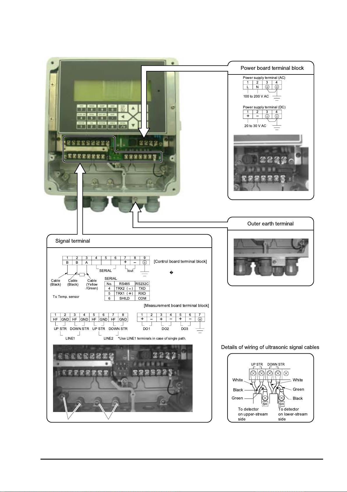
3.3.5. Wiring to each terminal
Install wiring according to the layout shown below.
( 2< 24
( ) *&'+
"$,,
## "## % &'
( ) *'+
"$
;
7
"# $# % &'
'2
*34+
!
3&
'2
$,
!
$"
'2
*5(
6-+
./
! -
&
3
*34+
-"-
"
0/.,
7
&
,1.
,
9"
()
.
9
()
/
01
! -
81
;
"$"'
9
;
9
7
':
=: 2< 24>
"
7
;
=' 2< 24>
$,./0
;;
"
7
$
7
( 2
34
-
<?
;
<
-
34
<
(;
<
INF-TN1FSH-E
- 17 -
Page 26
3.4. Setting piping parameters and calculating the
spacing between sensor units
Make the setting to calculate the spacing between the sensor units as follows.
3.4.1. Selecting sensor type, mounting the sensor
Description
The data of the sensor required for measurement can be set as follows.
If the sensor mounting method or sensor type is changed, the sensor spacing in piping specifications is also changed.
Enter the data for each item according to the display (see the table shown below).
Refer to 4.4.1 for details of the setting.
Item Input method Range or menu
Sensor mounting method Select V method, Z method
Sensor type Select FLW11, FLW41, FLW12, FLD12, FLD22, FLW32,
FLW50, FLW51, FSW12, FSW21, FSW40, FSW50
Sensor calibration
Line #-F: METAL PIPE
Line #-R: METAL PIPE
Line #-F: PLASTIC PIPE
Line #-R: PLASTIC PIPE
(#: Line No.)
*1) Select sensor type by the model of the sensor to be used in combination (5 digits).
*2) In sensor calibration, set the sensor constant calculated based on actual current calibration performed as part of the
delivery test at the factory. Set the sensor constant for each of the sensor units mounted to the pipe. The sensor
constant appears as the DF value marked on the nameplate of the sensor unit. The setting need not be changed
normally. (Make the setting when the detector or the flow transmitter is replaced.)
▪ It appears as the DF-P value on the nameplate of the sensor unit if the sensor is mounted on a plastic pipe.
▪ It appears as the DF-M value on the nameplate of the sensor unit if the sensor is mounted on a metal pipe.
Pipe material
Plastic Pipe PVC, FRP, PEEK, PVDF, Acrylic, Others
Metal Pipe Carbon steal, Stainless steel, Copper, Cast iron, Aluminium, Ductile iron
Refer to “1.3 Checking type and specifications” for sensor unit.
*3) The sensor calibration value is for the sensors in the following figure.
Numeric value
Numeric value
Numeric value
Numeric value
0.00% to 300.00%
0.00% to 300.00%
0.00% to 300.00%
0.00% to 300.00%
Sensor 3 Sensor 2
Direction of flow
Sensor 1 Sensor 4
Sensor calibration line 1-F: Sensor 1
Sensor calibration line 1-R: Sensor 2
Sensor calibration line 2-F: Sensor 3
Sensor calibration line 2-R: Sensor 4
*4) Perform sensor calibration only when the sensor type is FSW12, FSW21, FSW40, or FSW50.
To line 1
To line 2
- 18 -
Converter
INF-TN1FSH-E
Page 27
Operation (example) When Z method as sensor mount, FSW12 as sensor type, 102% for sensor calibration line 1-F
(METAL), 101% for 1-R (METAL)
Key operation Description Display
FUNC SYSTEM
S or T
ENTER S or T ENTER
Display System.
Select “SENSOR MOUNT”
Enter select/enter mode, select “Z
METHOD” and press ENTER.
UNIT & LANGUAGE
SENSOR MOUNT
SENSOR MOUNT
SKIP
V METHOD
Z METHOD
S or T
ENTER S or T ENTER
T
ENTER
ENTER 1 0 2 ENTER
or T
S
ENTER 1 0 1 ENTER
ESC
S
or
T
ENTER
ESC
Select “SENSOR TYPE”
Enter select/enter mode, select “FSW12”
and press ENTER.
Select “SENSOR CALIBRATION”
Enter select/enter mode, select “Setting,”
and press ENTER.
Enter numeric value enter mode, enter
“102” using ten keys, and press ENTER.
Select “LINE 1-R”
Enter numeric value enter mode, enter
“101,” and press ENTER.
Return to “SENSOR CALIBRATION”
Display measurement, reflecting the
setting.
SENSOR TYPE
SENSOR TYPE
SENSOR CALIBRATION
LINE 1-F: METAL
LINE 1-F: METAL
LINE 1-R: METAL
LINE 1-R: METAL
SENSOR CALIBRATION
(Measurement display screen)
FSW21
FSW12
SKIP
100.00%
102.00%
100.00%
101.00%
SKIP
INF-TN1FSH-E
- 19 -
Page 28
3.4.2. Entering piping specifications
Description
By setting the conditions of the piping where measurement is to be taken, the spacing between the sensor units to be
mounted can be calculated. The sensor spacing is calculated automatically.
Enter data for each item listed in the following table according to the display.
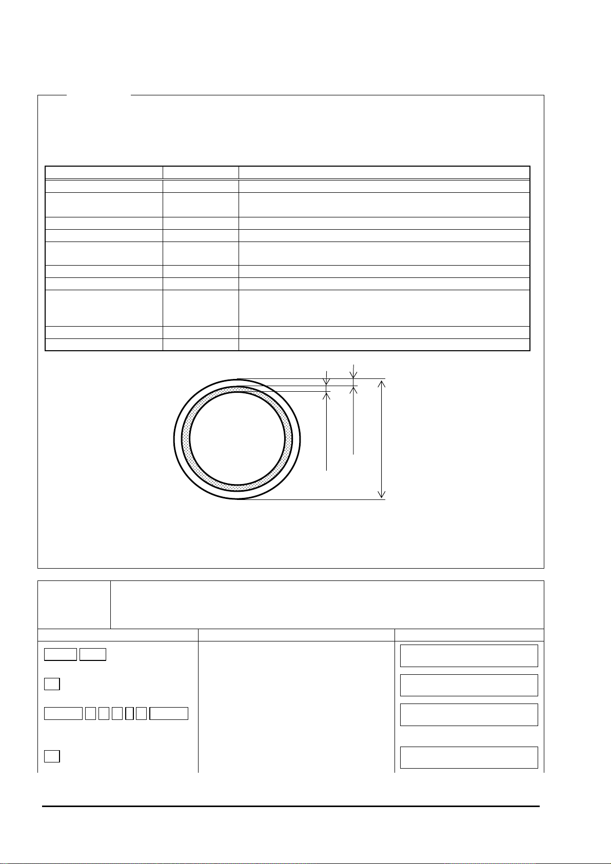
Item Input method Range or menu
Outer diameter Numeric value 10.00 mm to 6200.00 mm
Pipe material Select Carbon steel, stainless steel, PVC, copper, cast iron, aluminum,
FRP, ductile iron, PEEK, PVDF, acrylic, and others
Pipe S.V.*1 Numeric value 1000 m/s to 3700 m/s
Wall thickness Numeric value 0.10 mm to 100.00 mm
Lining material Select No lining, tar epoxy, mortar, rubber, Teflon, pyrex glass, PVC, and
others
Lining S.V.*2 Numeric value 1000 m/s to 3700 m/s
Lining thickness*3 Numeric value 0.01 mm to 100.00 mm
Kind of fluid Select Water, seawater, dist. water, ammonia, alcohol, benzene, bromide,
ethanol, glycol, kerosene, milk, methanol, toluol, lube oil, fuel oil,
petrol, and others
Fluid S.V.*4 Numeric value 500 m/s to 2500 m/s
Viscosity*4 Numeric value 0.0010E-6 m2/s to 999.9999E-6 m2/s
*1) When “others” is selected as pipe material only.
*2) When “others” is selected as lining material only.
*3) In the cases other than “No lining” only
*4) When “others” is selected for the kind of fluid only.
Operation
(example)
When outer diameter of the pipe is 114.3 mm, pipe material is carbon steel, wall thickness is 6.0 mm,
lining material is tar epoxy, lining thickness is 1.25 mm, kind of fluid is heavy water, sound velocity is
1388 m/s, and kinematic viscosity is 1.129E
(When the sensor is mounted by “Z method,” sensor type is “FSW12.”
Key operation Description Display
FUNC PIPE
T
ENTER 1 1 4 . 3 ENTER
Display sensor spacing.
Select “OUTER DIAMETER”
Enter numeric value enter mode, enter
114.30 using ten keys, and then press
ENTER.
6
−
m2/s
Lining thickness
Wall thickness
Outer diameter
SENSOR SPACING
OUTER DIAMETER
OUTER DIAMETER
9.17 mm
60.00 mm
114.30 mm
T
Select “PIPE MATERIAL”
- 20 -
PIPE MATERIAL
PVC
INF-TN1FSH-E
Page 29
ENTER
S or T ENTER
T
ENTER 6 ENTER
T
ENTER S or T ENTER
T
ENTER 1 . 2 5 ENTER
T
ENTER S or T ENTER
T
ENTER 1 3 8 8 ENTER
T
ENTER 1 . 1 2 9 ENTER
ESC
ESC
SENSOR SPACING
39.16 mm
Enter select/enter mode, select “CARBON
STEEL,” and then press ENTER.
Select “WALL THICKNESS”
Enter numeric value enter mode, enter “6”
using ten keys, and press ENTER.
Select “LINING MATERIAL”
Enter select/enter mode, select “TAR
EPOXY,” and press ENTER.
Select “LINING THICKNESS”
Enter numeric value enter mode, enter
“1.25” using ten keys, and press ENTER.
Select “KIND OF FLUID”
Enter select/enter mode, select “OTHERS,”
and press ENTER.
Select “FLUID S.V.”
Enter numeric value enter mode, enter
“1388” using ten keys, and press ENTER.
Select “VISCOSITY”
Enter numeric value enter mode, enter
“1.129” using ten keys, and press ENTER.
Select “SENSOR SPACING”
Display the measurement, reflecting the
setting.
PIPE MATERIAL
WALL THICKNESS
WALL THICKNESS
LINING MATERIAL
LINING MATERIAL
LINING THICKNESS
LINING THICKNESS
KIND OF FLUID
KIND OF FLUID
FLUID S.V.
FLUID S.V.
VISCOSITY
VISCOSITY
SENSOR SPACING
(Measurement display screen)
CARBON STEEL
4.50 mm
6.00 mm
NO LINING
TAR EPOXY
0.01 mm
1.25 mm
Water
OTHERS
1440 m/s
1388 m/s
6m2
1.0038 E
1.1290 E
39.16 mm
−
6m2
−
← Set the piping data, and then mount the detector at dimensions displayed.
/s
/s
INF-TN1FSH-E
- 21 -
Page 30
3.5. Installing Detector
3.5.1. Outline of detector installation procedure
1. Treatment of mounting surface of the detector
2-1 Mounting small-diameter and small/medium size sensor
(1) How to mount the frame (using a jig)
(2) How to mount the frame (not using a jig)
(2)-1 How to determine the mounting position
(2)-2 How to mount the frame
(3) How to mount the sensor unit
2-2 Mounting a large sensor
(1) Mounting position
(2) How to mount the sensor
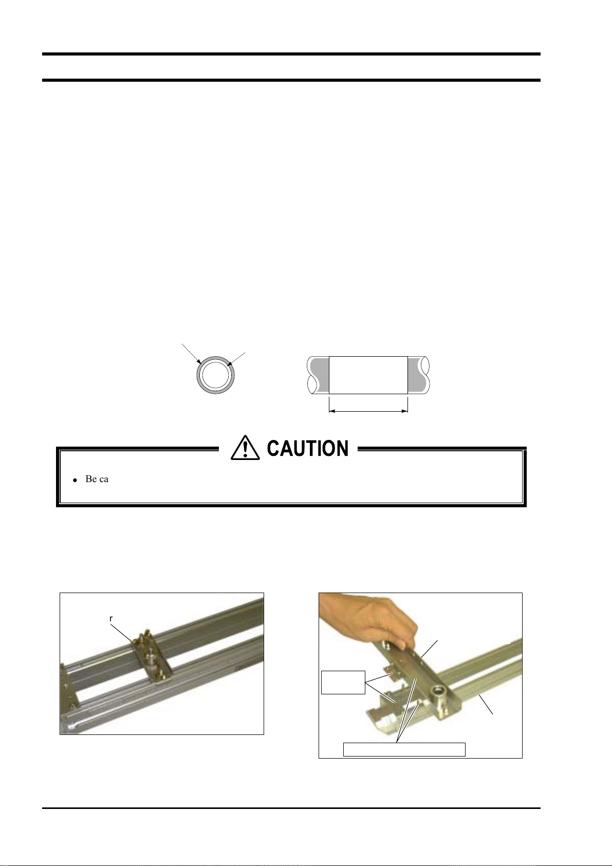
3.5.2. Treatment of mounting surface
Using thinner and sand paper, remove rust, pitch, and irregularities, if any, on the surface of the piping to which the
detector is to be mounted over the length of the frame to be used.
Note 1: If the pipe is wrapped with jute, remove the jute wrapping over the entire circumference in width of frame
length (L) + 200 mm, and then perform surface treatment described above.
Jute wrapping
Pipe
L + 200 mm
CAUTION
Be careful not to cut your hand with the stainless steel belt when mounting the frame.
•
Mount the sensor unit equipped with a temperature sensor on the upstream side.
•
3.5.3. Mounting the detector by Z method using the frame
(1) How to mount the frame (using a jig)
(1) Remove the butterfly nut of the cursor, and remove
it out of the frame.
Cursor
(2) Temporarily place the mounting jig (option) on the
frame.
Insert
the pins.
Mounting jig
Frame
- 22 -
Let the screws run through.
INF-TN1FSH-E
Page 31

w
(3) Fasten the mounting jig to the frame using the
butterfly nut and the screw.
Scre
Butterfly nut
(4) Mount the mounting jig on the opposite side of the
frame.
(6) Let the shaft run through the mounting jig on the
opposite side.
(7) Place the frame between the pipes.
(5) Let the shaft run through the mounting jig.
Note: Pay attention when letting the shaft run
through the jig so that the scale unit of the
frame coincides with that of the shaft.
Select the same scale (mm, inch).
Shaft
Mounting jig
(8) Let the shaft run through the holes at the bottom of
the mounting jig.
Shaft
INF-TN1FSH-E
- 23 -
Page 32

(9) Wrap the stainless belt around the frame end.
Frame end
(10) Lift the screw of the stainless belt to let the tip of the
belt run through it.
(11) Fasten the screw, wrapping the stainless belt around
the frame end.
(12) Fasten both ends of the frame with the stainless belt.
(13) Remove the mounting jig.
Remove the shaft first, and then remove the
mounting jig.
- 24 -
INF-TN1FSH-E
Page 33

(2) How to mount the frame (not using a jig)
Gage paper is required to mount the frame by this method. (See “8.7. Making gauge paper” for details.)
(2)-1 How to determine the mounting position
(1)
Align the edge of the gauge paper to the
place 100mm from one of the edges treated for
mounting, and wrap it around the pipe, keeping
the line on the gauge paper in parallel with the
axis of the pipe. (Fasten with tape to prevent it
from being dislocated.) Keep the edge of the
gauge paper at specified position.
Keep the line
in position.
100mm
(2)
Write straight line A on the pipe, extending
the line written on the gauge paper.
(3)
Write a line along one edge of the gauge
paper. Let the point of intersection of that line
and line A be A
0.
V method Z method
Example: When L=200mm
A2
(4)
Peel off the gauge paper,
A0
200mm
measure the sensor spacing from
A
0, and draw a line that intersects
with straight line A at right angles.
(Find A
2.)
From A0 to A2 is defined
as the mounting position.
Line A
A0
A0 B0, B1 A0, A1A1
B1
(4)
Measure the circumference beginning from A0 using a
B0
Straight line B
measure. Determine the points that equally divide the
circumference and let them be B
0 and B1 respectively.
Draw a line connecting these two points (straight line B).
Example: When L=100mm
100mm
B0B2
INF-TN1FSH-E
B0B2
A0
(5)
Mark point B
Measure the sensor spacing from B
intersects with straight line B at right angles. (Find B
From A
0, and then peel off the gauge paper.
0, and draw a line that
2.)
0 to B2 is defined as the mounting position.
- 25 -
Page 34

(2)-2 Mounting the Frame
(1) Checking the mark-off line
“In the case of 1 measurement line”
Draw a horizontal mark-off line that
includes the center point of the cross
sectional view of the pipe.
Mark-off line
Mark-off
line
(2) Wrap the stainless belt around the pipe.
“In the case of 2 measurement lines”
Draw a mark-off lines at an angle ±45°
from the horizon.
45°
45°
(4) Place the frame so that the marking line and the “V”
mark on the frame end are aligned, and then fasten it
with a band.
Mark-off line
Mark-off line
(3) Lift the screw of the stainless belt and let the tip of
the belt run through it.
Marking
line
Align the "▽" mark with
the marking line.
- 26 -
INF-TN1FSH-E
Page 35

(3) How to mount the sensor unit
Mount the sensor unit comprising of two sensors facing opposite to each other, keeping the spacing displayed after the
piping parameter setting is completed. See “2.2.3. Mounting the sensor” for details.
Note: Mount the sensor unit equipped with a temperature sensor on the upstream side.
(1) Before mounting the sensor unit to the frame, apply
silicon rubber evenly over the entire transmitting
surface of the sensor unit and the surface of the
thermometer that is to contact the pipe.
(4) Fasten the sensor unit with butterfly nuts. Then
bring the sensor unit into intimate contact with the
pipe, fastening the cap screw.
(2) Temporarily place the cursor on the sensor unit.
Cursor
(3) Insert the sensor unit into the frame, aligning the
holes of the cursor with the screws of the frame.
Cap screw
(5) Mount the sensor unit, paying attention to the
spacing of the sensors facing opposite to each other.
(6) Mount the two sensors with the front surface of each
facing to each other. Mount only one sensor to one
frame.
Mounting of resin piping has now been completed. In
the case of metal piping, mount the absorber unit as
shown below.
(7) Before mounting the absorber unit, apply silicon
rubber evenly over the entire installation surface of
the absorber unit.
Screw
INF-TN1FSH-E
Hole
- 27 -
Page 36

(8) Temporarily place the cursor onto the absorber unit.
Cursor
Absorber
unit
(9) Aligning the screws of the frame to the holes of the
cursor, insert the absorber unit into the frame.
Screw
(10) Fasten the absorber unit with the butterfly nut at the
position where the absorber unit comes in contact
with the sensor unit. Then fasten the cap screw.
(11) Fasten the absorber unit onto both frames.
Hole
- 28 -
INF-TN1FSH-E
Page 37

3.5.4. Mounting the sensor unit by V method using a frame
(1 measurement line)
(1) Mounting the frame
Unlike Z method, only one frame is used. No mounting jig is used.
(1) Wrap the stainless steel belt around the pipe.
(3) Wrap the stainless steel belt around the frame ends,
keeping the frame in parallel with the pipe, to fasten
the frame temporarily.
(2) Lift the screw of the stainless belt to let the tip of the
belt run through it.
Frame end
INF-TN1FSH-E
- 29 -
Page 38

(2) Mounting the sensor unit
Mount both sensor units at the spacing shown in “Sensor spacing” that is to be displayed after pipe parameter setting is
made. The spacing is the distance between the tips of both sensors.
Note: Mount the sensor unit equipped with a temperature sensor on the upstream side.
(1) Apply silicon rubber evenly over the entire
transmission surface of the sensor unit and the
contact surface of the pipe of the thermometer
before mounting the sensor unit to the frame.
(4) Fasten the sensor unit with butterfly nuts. Then
bring the sensor unit into intimate contact with the
pipe, fastening the cap screw.
(2) Temporarily place the cursor on the sensor unit.
Cursor
(3) Insert the sensor unit into the frame, aligning the
holes of the cursor with the screws of the frame.
Cap screw
(5) Mount the sensor unit opposing to each other,
paying attention to the mounting spacing. (Mount
the two sensors with the front of each facing
opposite to each other.)
Note:
The sensor can be mounted by V method only when
transit time method is employed. Consequently an
absorber is not used even if the pipe is made of metal.
Screw
Hole
- 30 -
INF-TN1FSH-E
Page 39

3.5.5. Mounting the sensor unit by Z method using a frame
(2 measurement lines)
(1) Mounting the frame
Two pairs of frames are required.
(1) Draw a mark-off line at an angle ±45° from the horizon. See 3.5.7. (1) how to draw a mark-off line.
45°
45°
(2) Align the center of the end frame so that it comes over the make-off line, and temporarily fasten it using cloth
belt, etc. not on the frame ends but on the frame.
(3) Then wrap a stainless steel belt around the frame end to fasten it securely. Follow the description in 3.5.3. to
fasten the stainless steel belt.
(2) Mounting the sensor unit
Two pairs of sensor units and two pairs of absorbers (in the case of a metal pipe) are required for mounting. Mount the
sensor units following the same procedure as “3.5.3.(3) How to mount the sensor unit.” Mount each pair of frames to
install the sensor unit.
Mark-off line
Mark-off line
45°
45°
Frame
INF-TN1FSH-E
- 31 -
Page 40

3.5.6. Mounting the sensor unit by V method using a frame
(2 measurement lines)
(1) Mounting the frame
The method is valid only when transit time method is employed. Two pairs of sensor units and 2 frames are required
for this measurement method. Mount the frames following the same procedure as Z method.
(2) Mounting the sensor unit
Follow the same procedure as “3.5.4.(2) Mounting the sensor unit.” to mount the sensor unit. Mount each frame to
install the sensor unit.
45°
45°
Mark-off line
Mark-off line
Frame
45°
45°
- 32 -
INF-TN1FSH-E
Page 41

3.5.7. Mounting the sensor unit to a large-diameter pipe
(1) How to determine the mounting position
Do not use a mounting jig to install the sensor unit to a pipe of diameter of 500 A or more. Mount the sensor with wire
in such cases. (Do not use a frame.)
Perform the following to determine the mounting position.
Gauge paper is required for the work. (See “8.7. Making gauge paper” for details.)
(1)
Align the edge of the gauge paper to the
place 100mm from one of the edges treated for
mounting, and wrap it around the pipe, keeping
the line on the gauge paper in parallel with the
axis of the pipe. (Fasten with tape to prevent it
from being dislocated.) Keep the edge of the
gauge paper at specified position.
Keep the line
in position.
100mm
(2)
Write straight line A on the pipe, extending
the line written on the gauge paper.
(3)
Write a line along one edge of the gauge
paper. Let the point of intersection of that line
0
and line A be A
.
V method Z method
Example: When L=200mm
A
A
2
200mm
(4)
Peel off the gauge paper,
0
measure the sensor spacing from
A
0
, and draw a line that intersects
with straight line A at right angles.
(Find A
2
.)
From A0 to A2 is defined
as the mounting position.
Line A
A
0
A
0
Straight line B
0
A
1
B
(4)
Measure the circumference beginning from A
B
1
B
0, B1
measure. Determine the points that equally divide the
circumference and let them be B
0 and B1 respectively.
Draw a line connecting these two points (straight line B).
Example: When L=100mm
100mm
B0B
2
A
0, A1
0 using a
INF-TN1FSH-E
A
B
0
2
0, and then peel off the gauge paper.
(5)
Mark point B
B
Measure the sensor spacing from B
intersects with straight line B at right angles. (Find B
From A
0
to B2 is defined as the mounting position.
0
0, and draw a line that
2.)
- 33 -
Page 42

(2) Mounting the sensor
Use sensor FSW50 for large-diameter pipes.
Note: Mount the sensor unit equipped with a temperature sensor on the upstream side.
(1) Checking the mark-off line
“In the case of 1 measurement line”
Draw a horizontal mark-off line that
includes the center point of the cross
“In the case of 2 measurement lines”
Draw a mark-off lines at an angle ±45°
from the horizon.
sectional view of the pipe.
Mark-off line
45°
Mark-off
line
(2) Provide a wire rope for the sensor unit on the
upstream and downstream sides and the absorber
unit. Allow the length of the wire rope to be the
same or longer than the pipe diameter.
(4) Apply silicon rubber evenly over the entire
transmitting surface of the sensor unit, paying
attention not to let air bubbles mix in.
45°
Mark-off line
Mark-off line
(3) Lay the wire rope around the pipe on the upstream
side. Then hang the spring for mounting on the
wire rope.
(5) Clean the surface of the piping, and then mount the
sensor unit.
- 34 -
INF-TN1FSH-E
Page 43

(6) Split up the wire rope around the marking line to
right and left, bring the sensor unit into intimate
contact with the pipe, and then lay the wire rope
around them, paying attention to let the marking of
the sensor unit be aligned with the marking line.
Spring for mounting
Sensor
Marking line
Pipe
Transmission mark
Marking line
Matching mark
(7) Check that the matching mark on the sensor unit and
the marking line are aligned, and then connect the
coaxial cable to the flow transmitter.
Note: Do not pull the coaxial cable. Otherwise
the sensor unit may move, thus causing
measurement trouble.
Marking
line
(10) Clean the surface of the pipe, and then mount the
absorber unit. Split up the wire rope to right and
left, bring the absorber unit into intimate contact
with the sensor unit, and then lay the wire rope
around them.
(11) Follow the same procedure to mount the sensor on
the downstream side.
Cable side
Transmission marker side
Upstream side
(8) Lay the wire rope on the side provided with the
transmission marker.
(9) Apply silicon rubber evenly over the entire
installation surface of the absorber unit.
Downstream side
Cable sideTransmission marker side
INF-TN1FSH-E
- 35 -
Page 44

3.6. Setting analog output range and total pulse
The following table lists the analog output and total pulse settings.
3.6.1. Analog output range setting
Description
Make the setting as shown below when outputting the measured value (flow rate or flow velocity) in specified range
within 4 to 20 mA.
The following is an example of operation. Refer to 4.4.4. for details of the setting.
Operation
(example)
In the case of Bi-directional range, and full scale 1 set to 100 m
hys. to 5%, lower limit to −10% (2.4 mA), upper limit to 110% (21.6 mA), output burnout to the lower
limit value, burnout timer to 30 seconds, rate limit to 5 m
Key operation Description Display
FUNC RANGE
ENTER S or T ENTER
T
ENTER S or T ENTER
T
ENTER 1 0 0 ENTER
T
ENTER ± 1 0 0 ENTER
3
/h, and rate limit timer to 15 sec.
Display range unit.
3
Enter select/enter mode, select “m
/h,” and
press ENTER.
Select “RANGE TYPE”
Enter select/enter mode, select
“Bi-directional” range, and press ENTER.
Select “FULL SCALE 1”
Enter numeric value enter mode, enter “100”
using ten keys, and press ENTER.
Select “FULL SCALE 2”
Enter numeric value enter mode, enter
"−100” using ten keys, and press ENTER.
3
/h, full scale 2 to −100 m3/h, range
RANGE UNIT
RANGE UNIT
RANGE TYPE
RANGE TYPE
FULL SCALE 1
FULL SCALE 1
FULL SCALE 2
FULL SCALE 2
m/s
3
m
/h
SINGLE
BI-DIR
56.32 m
100.0 m
112.64 m
100 m
−
3
/h
3
/h
3
/h
3
/h
T
ENTER 5 ENTER
T
ENTER 1 0 ENTER
T
ENTER 1 1 0 ENTER
T
ENTER S or T ENTER
T
Select “RANGE HYS.”
Enter numeric value enter mode, enter “5”
using ten keys, and press ENTER.
Select “OUTPUT LIMIT Lo.”
Enter numeric value enter mode, enter “10”
using ten keys, and press ENTER.
Select “OUTPUT LIMIT Hi.”
Enter numeric value enter mode, enter “110”
using ten keys, and press ENTER.
Select “OUTPUT BURNOUT”
Enter select/enter mode, select “LOWER,”
and press ENTER.
Select “BURNOUT TIMER”
- 36 -
RANGE HYS.
RANGE HYS.
OUTPUT LIMIT Lo.
OUTPUT LIMIT Lo.
OUTPUT LIMIT Hi.
OUTPUT LIMIT Hi.
OUTPUT BURNOUT
OUTPUT BURNOUT
BURNOUT TIMER
10.00%
5.00%
20%
−
10%
−
120%
110%
HOLD
LOWER
10 sec
INF-TN1FSH-E
Page 45

ENTER
3 0 ENTER
T
ENTER 5 ENTER
T
ENTER 1 5 ENTER
ESC
Enter numeric value enter mode, enter “30”
using ten keys, and press ENTER.
Select “RATE LIMIT”
Enter numeric value enter mode, enter “5,”
and press ENTER.
Select “RATE LIMIT TIMER”
Enter numeric value enter mode, enter “15”
using ten keys, and press ENTER.
Display the measurement, reflecting the
setting.
BURNOUT TIMER
RATE LIMIT
RATE LIMIT
RATE LIMIT TIMER
RATE LIMIT TIMER
(Measurement display screen)
30 sec
0.00 m
5.00 m
0 sec
15 sec
3
/h
3
/h
INF-TN1FSH-E
- 37 -
Page 46

3.6.2. Total pulse output setting
Description
Make the setting to perform pulse output of the total measurement value (flow rate).
The following is an example of operation. Refer to 4.4.9. and 4.4.11. for details of the setting.
Definition of total pulse to DO
(example)
Key operation Description Display
FUNC STATUS
ENTER S or T
ENTER
ENTER S or T ENTER
S or T
ENTER S or T ENTER
ESC ESC
Total setting (example) When performing integration, holding output burnout with total pulse output set to 100 m
Key operation Description Display
FUNC TOTAL
ENTER S or T ENTER
When DO1 is output as total pulse output in forward direction
Display Status.
SELECT STATUS
Select “DO.1.”
Display “OUTPUT DO.1”
SELECT STATUS
OUTPUT DO.1
Enter select/enter mode, select “F: TOTAL
PULSE,” and press ENTER.
Display “MODE DO.1”
OUTPUT DO.1
MODE DO.1
Enter select/enter mode, select “NORMAL,”
and press ENTER.
Display the measurement, reflecting the
setting.
MODE DO.1
(Measurement display screen)
for 1 pulse, burnout timer set to 15 sec, and pulse width 1 set as 100msec.
Display Total mode.
TOTAL MODE
Enter select/enter mode, select “TOTAL
STOP,” and press ENTER. (Setting is
allowed.)
TOTAL MODE
DO.1
▲
▼
DO.1
NOT USED
F: TOTAL PULSE
REVERSE
NORMAL
TOTAL RUN
TOTAL STOP
3
S or T
ENTER S or T ENTER
S or T
ENTER 1 0 0 ENTER
S or T
ENTER S or T ENTER
S or T
ENTER 1 5 ENTER
S or T
Select “TOTAL UNIT”
3
Enter select/enter mode, select “m
,” and
press ENTER.
Select “TOTAL RATE”
Enter numeric value enter mode, enter “100”
using the ten key, and press ENTER.
Select “OUTPUT BURNOUT”
Enter select/enter mode, select “HOLD,”
and press ENTER.
Select “BURNOUT TIMER”
Enter numeric value enter mode, enter “15”
using ten keys, and press ENTER.
Select “PULSE WIDTH 1”
- 38 -
TOTAL UNIT
TOTAL UNIT
TOTAL RATE
TOTAL RATE
OUTPUT BURNOUT
OUTPUT BURNOUT
BURNOUT TIMER
BURNOUT TIMER
PULSE WIDTH 1
mL
3
m
10.000 m
100.000 m
NOT USED
HOLD
10 sec
15 sec
50 msec
3
3
INF-TN1FSH-E
Page 47

ENTER
S or T ENTER
S or T
ENTER S or T ENTER
ESC
Enter select/enter mode, select “100,” and
press ENTER.
Select “TOTAL MODE”
Enter select/enter mode, select “TOTAL
RESET,” and press ENTER.
Display the measurement, reflecting the
setting.
PULSE WIDTH 1
TOTAL MODE
TOTAL MODE
(Measurement display screen)
100 msec
TOTAL STOP
TOTAL RESET
INF-TN1FSH-E
- 39 -
Page 48

3.7. Zero adjustment
Description
Close the valves on upper and lower streams of the flowmeter to stop the flow completely, and then perform zero
adjustment.
Note 1: If no valves are provided or the flow cannot be stopped, select “Clear” when performing “Zero adjustment.”
Note that zero point may deviate slightly in this case.
Note 2: ZERO: Press “Zero” to perform zero adjustment in a state where the flow is stopped completely.
CLEAR: Press “Clear” to perform zero adjustment in a state where the flow cannot be stopped.
Operation (example) When performing zero adjustment in still state
Key operation Description Display
FUNC ZERO
ENTER S or T
ENTER
Display zero adjustment.
Enter select/enter mode, and select “ZERO”
While calibration is in progress, elapsed time is
displayed in lower stage.
ZERO ADJUSTMENT
ZERO ADJUSTMENT
ZERO ADJUSTMENT
CLEAR
ZERO
▲
▼
When calibration is successfully completed, “ZERO”
is displayed. When it is unsuccessfully completed,
“CLEAR” is displayed in lower stage.
ESC
Display the measurement, reflecting the setting.
ZERO ADJUSTMENT
(Measurement display screen)
ZERO
CAUTION
If “Clear” is selected and executed at this time, the zero adjustment value currently stored is cleared to
•
zero.
- 40 -
INF-TN1FSH-E
Page 49

m
4. SETTING PARAMETERS
4.1. Description of display/setting unit
4.1.1. Description of display
Turn on the power, and the following display appears. The meaning of displayed numeric values and symbols are as
follows.
RAS display
Measurement screen
Measurement method
H
D
T
0 000.
m/s
Display
2
3
0000.
Measurement display
Direction of flow
If the fluid is flowing in reverse direction or the upstream and the downstream
of the sensor connection are reversed, “−” appears.
/s
4.1.2. Description of keys
Press the key, and the functions displayed above the ten keys can be executed.
Duosonics
Display
1
INF-TN1FSH-E
PIPE
7
FLOW SW
4
STATUS
1
8
TOTAL
5
CAL
2
9
CUT OFF
6
SYSTEM
3
0
DISP
・
CHECK
±
DETAIL
/π
ESC
ENTER
FUNC
ZERO
DAMP
RANGE
- 41 -
Page 50

Table 1 Description of keys
Name Key Description
to 9 , ・ ,
0
Ten key
±
Used to enter numeric values for data and piping specifications.
Press this key to set the numeric data entered using keys or
ENTER ENTER
items selected by dialog. In the case of entry by dialog, the
next item to be set appears.
Left arrow key, Right arrow
key
Up arrow key, Down arrow
key
W
S
, X
, T
Used to move the cursor when changing numeric values.
Press e to move the selection to left, and press f to move the
selection to right.
Press c to go to the next menu, and press d to go back to the
previous menu.
Used to select the menu item displayed during dialog.
ESCAPE (Cancellation) ESC Used to cancel the dialog.
FUNCTION
Press this key to execute the function displayed above each key
(ten keys).
Enter the outer periphery of the pipe and press this key, and the
/π
/π
outer diameter is displayed (valid only when outer pipe
diameter is selected).
PIPE (Piping specifications)
RANGE (Output setting)
FUNC
FUNC
PIPE
RANGE
Used to enter the dimensions, material, etc. of the pipe to which
the sensor is to be mounted.
Used to set the analog output conditions (unit, range, limit,
burnout, rate limit).
DAMP (Damping) FUNC DAMP Used to set damping.
ZERO (Zero adjustment) FUNC ZERO Used to set zero adjustment.
DISP (Display setting)
CUT OFF (Low flow rate
cutoff)
TOTAL (Integration)
FLOW SW (Flow switch)
STATUS (Status output)
FUNC
FUNC
FUNC
FUNC
FUNC
DISP
CUT OFF
TOTAL
FLOW SW
STATUS
Used to set items and units that appear on the measurement
screen.
Used to set low flow rate cutout.
Used to set the conditions of flow rate integration (unit, rate,
preset value, total switch, pulse width).
Used to set the upper/lower limit switch of the measurement
value.
Used to set the conditions of status output (total pulse,
measurement status).
CAL (Output calibration) FUNC CAL Used to calibrate the reading of zero point and 100% point.
SYSTEM
CHECK
DETAIL (Details of
measurement)
FUNC
FUNC
FUNC
SYSTEM
CHECK
DETAIL
Used to switch measurement unit systems and languages, and
check or calibrate analog output.
Displays error contents and measurement status in case an error
display appears.
Used to display the version of software or perform detailed
measurement setting.
- 42 -
INF-TN1FSH-E
Page 51

4.2. Setting item list
Refer to Appendix “8.5. Composition of key operation” for details of composition of key operation.
Measurement
screen
*1) Intended for our service personnel.
Piping specifications
( FUNC
PIPE )
Output setting
( FUNC
Damping
( FUNC
Zero adjustment
( FUNC
Display setting
( FUNC
Low flow rate cutout
( FUNC
RANGE )
DAMP )
ZERO )
DISP )
CUT OFF )
Integration
( FUNC
Flow switch
( FUNC
Status output
( FUNC
Output calibration
( FUNC
TOTAL )
FLOW SW )
STATUS )
CAL )
System
( FUNC
Details of measurement
( FUNC
SYSTEM )
*1
DETAIL )
4.4.2.
Range unit, range type, full scale 4.4.4.1.
Output limit 4.4.4.2.
BURNOUT 4.4.4.3.
Rate limit 4.4.4.4.
4.4.5.
4.4.6.
4.4.7.
4.4.8.
Total unit 4.4.9.1.
Total pulse (Total rate, pulse width) 4.4.9.2.
Total preset 4.4.9.3.
Total switch 4.4.9.4.
BURNOUT 4.4.9.5.
4.4.10.
4.4.11.
4.4.12.
System unit 4.4.13.
System language 4.4.14.
Serial communication 4.4.15.
Calibration and check of analog output 4.4.16.1.
Check of status output 4.4.16.2.
Calibration of wedge temperature 4.4.16.3.
Check of wedge temperature 4.4.16.4.
Test mode 4.4.16.5.
Measurement method 4.4.1.
Sensor
(Mounting method, type, calibration, transmission
voltage)
Measurement mode 4.4.3.
LCD backlight 4.4.17.
Key lock 4.4.18.
Transit time 4.4.20.1
Pulse Doppler 4.4.20.2.
Initialization 4.4.20.3.
4.4.1.
INF-TN1FSH-E
- 43 -
Page 52

4.3. Parameter specification table
The following table lists factory settings (not applicable to the type with parameter settings).
No. Setting item Settable range Initial value Settable value
1 Outer diameter 10.00 to 6200.00 mm
(0.393 to 244.100 inch)
2 Pipe material 12 menus PVC Carbon steel, Stainless steel, PVC,
3 Wall thickness 0.10 to 100.00 mm
(0.003 to 3.940 inch)
4 Lining material 8 menus
Lining S.V.: 1000 to 3700
m/s (3280 to 12140 ft/s)
5 Lining thickness 0.01 to 100.00 mm
(0.000 to 3.940 inch)
6 Kind of Fluid 17 menus
Fluid S.V.: 500 to 2500m/s
(1641 to 8203 ft/s)
PiPing specification
7
Range unit 19 menus m/s (ft/s) m/s, L/s, L/min, L/h, L/d, kL/d,
Viscosity: 0.001 to
999.9999 × 10
(0.0107 to 10763.9088 ×
-6
ft2/s)
10
-6m2
/s
8 Range type 4 menus Single Single, Auto 2, Bi-dir, Bi-dir Auto 2
9 Full scale or Full
scale 1
In terms of flow velocity
0.00, ±0.30 to ±32.00m/s
(0.00, ±0.98 to ±104.98
ft/s)
10 Full scale 2 In terms of flow velocity
0.00, ±0.30 to ±32.00m/s
(0.00, ±0.98 to ±104.98
ft/s)
11 Range HYS. 0.00 to 20.00% 10.00% %
12 Output limit LO.
13 Output limit HI. 100 to 120% 120% %
Range setting
20 to 0%
−
14 Output burnout 5 menus Hold Not used, Hold, Upper, Lower, Zero
15 Burnout timer 0 to 900sec 10sec sec
16 Rate limit 0.00 to 5.00m/s (0.00 to
16.40 ft/s) in terms of flow
velocity
17
Rate limit timer 0 to 900sec 0 sec sec
18 Damping 0.0 to 100.0sec 5.0 sec sec
19 Zero adjustment 2 menus
20 1: Display kind 7 menus Flowrate
21
2: Display kind 7 menus Velocity
setting
Display
60.00 mm
[mm, inch]
(2.362 inch)
Copper, Cast iron, Aluminum, FRP,
Ductile iron, PEEK, PVDF, Acrylic,
Others
4.00 mm
[mm, inch]
(0.157 inch)
No lining No lining, Tar epoxy, Mortar,
Rubber, Teflon, Pyrex glass, PVC,
Others (Sound velocity: [m/s, ft/s])
−
[mm, inch]
Water Water, Seawater, DIST. water,
Ammonia, Alcohol, Benzene,
Bromide, Ethanol, Glycol,
Kerosene, Milk, Methanol, Toluol,
Lube oil, Fuel oil, Petrol, Others
(Sound velocity: [m/s, ft/s])
(Viscosity [× 10
ML/d, m
3
km
/d, Mm3/d, BBL/s, BBL/min,
BBL/h, BBL/d, KBBL/d, MBBL/d
3
(ft/s, ft
Mft
/s, ft3/min, ft3/h, ft3/d, kft3/d,
3
/d, gal/s, gal/min, gal/h, gal/d,
-6m2
/s, ft2/s])
3
/s, m3/min, m3/h, m3/d,
kgal/d, Mgal/d, BBL/s, BBL/min,
BBL/h, BBL/d, kBBL/d, MBBL/d)
2.00 m/s
[(19) Unit]
(6.56 ft/s)
4.00 m/s
[(19) Unit]
(13.12 ft/s)
20%
−
0.00m/s
%
[(19) Unit]
(0.00 ft/s)
Clear
Zero, Clear (Default: Clear)
(unadjusted)
Velocity, Flowrate, Total forward,
(m3/s)
Total reverse, F: Total pulse, R:
Total pulse, Flow rate (%)
Velocity, Flowrate, Total forward,
(m/s)
Total reverse, F: Total pulse, R:
Total pulse, Flow rate (%)
- 44 -
INF-TN1FSH-E
Page 53

No. Setting item Settable range Initial value Settable value
22 Low flow cut off 0.00 to 5.00m/s (0.00 to
16.40 ft/s) in terms of flow
0.01 m/s
(0.03 ft/s)
[(19) Unit]
velocity
23 Total mode 3 menus Total stop Total stop, Total run, Total reset
24 Total unit 8 menus mL (ft3) mL, L, m3, km3, Mm3, mBBL, BBL,
kBBL, (ft
3
, kft3, Mft3, kgal, gal,
mBBL, BBL, kBBL, ACRF)
25 Total rate 0.000 to 999999.999 0.000 [(8) Unit]
26 F: Total preset 0.000 to 9999999999.999 0.000 [(8) Unit]
27 F: Total SW 0.000 to 9999999999.999 0.000 [(8) Unit]
28 R: Total preset 0.000 to 9999999999.999 0.000 [(8) Unit]
Total
29 R: Total SW 0.000 to 9999999999.999 0.000 [(8) Unit]
30 Output burnout 2 menus Hold Not used, Hold
31 Burnout timer 0 to 900sec 10 sec sec
32 Pulse width 1 3 menus 50 ms 50, 100, 200
33
Pulse width 2 9 menus 50.0 ms 0.5, 1.0, 2.0, 5.0, 10.0, 20.0, 50.0,
100.0, 200.0
34 Flow sw low In terms of flow velocity
0.00 to ±32.00 m/s (0.00 to
104.98 ft/s)
±
35 Flow sw high In terms of flow velocity
0.00 to ±32.00 m/s (0.00 to
36
Flow switch
Flow sw HYS. 0 to 20% 10% %
104.98 ft/s)
±
0.00 m/s
(0.00 ft/s)
4.00 m/s
(13.12 ft/s)
[(19) Unit]
[(19) Unit]
37 Output DO.1 15 menus Not used Not used, Signal error, F: Total
pulse, R: Total pulse, F: Total alarm,
R: Total alarm, F: Total overflow, R:
Total overflow, Flow SW high,
Flow SW Low, Full scale2, AO
range over, Pulse range over, R:
Flow direction, Device error
38 Mode DO.1 2 menus Normal Normal, Reverse
39 Output DO.2 15 menus Not used Same as DO1 output type
Status output
40 Mode DO.2 2 menus Normal Normal, Reverse
41 Output DO.3 15 menus Not used Same as DO1 output type
42
43 CAL. zero 0.00 to 5.00 m/s (000 to
Mode DO.3 2 menus Normal Normal, Reverse
16.40 ft/s) in terms of flow
0.00 m/s
(0.00 ft/s)
[(19) Unit]
velocity
44
range
CAL. span
200.00%
±
100.00% %
Calibration
45 System unit 2 menus Metric Metric, English
46 Language 5 menus English Japanese, English, German, French,
Spanish
47 COM. speed 3 menus 38400 bps 9600 bps, 19200 bps, 38400 bps
48 COM. parity 3 menus None None, Even, Odd
49 COM. stop bit 2 menus 1 bit 1bit, 2 bits
50 Serial method 2 menus RS232C RS232C, RS485
51
52 Analog output
53
System
Serial com.
calibration
Wedge temp.
StationNo. 31 menus 1 1 to 31
4 mA, 20 mA Calibration
-
value
100 Ω, 140 Ω
Calibration
-
value
INF-TN1FSH-E
- 45 -
Page 54

No. Setting item Settable range Initial value Settable value
54 Measure method 2 menus Hybrid Hybrid, Transit time
55 Measurement
2 menus 1 Path 1 Path, 2 Path
mode
56
AO definition 3 menus Line 1 Average, Line 1, Line 2
mode
Measurement
57 Mount 2 menus Z Method V Method, Z Method
58 Type 4 menus FSW12 FSW12, FSW21, FSW40, FSW50
59 Calibration 0.00 to 300.00% Calibrated
60
61 LCD display
System
Sensor
value
Trans. voltage 4 menus 80 Vpp 20 Vpp, 40 Vpp, 80 Vpp, 160 Vpp
3 menus On On, Off, Auto
%
backlight
62 Key lock 2 menus Off On, Off
63
64 #: Transmission
Password Numeral 4 digits 0000 4-digit numeral
6 menus 128 8, 16, 32, 64, 128, 256
count
65 #: Trigger
2 menus Auto Auto, Manual
control
66 #: Window
2 menus Auto Auto, Manual
control
67 #: Saturation
0 to 256 32
level
68 #: Measurement
3 menus Method 2 Method 1, Method 2, Method 3
method
69 #: Signal
Transit time
0 to 100% 25% %
balance
70 #: Transmission
pattern
7 menus Burst 3 Burst 1, Burst 2, Burst 3, Burst 4,
Burst 5, Chirp 4, Chirp 8
71 #: AGC gain 2 menus Auto Auto, Manual
72 #: Signal peak 4 menus 3071 2048, 3071, 4096, 5120
73
#: Trans. wait
1 to 30 msec 3 msec msec
time
74 Wedge S.V. 2 menus Auto Auto, Manual
75 Pipe S.V. 2 menus Auto Auto, Manual
76 Lining S.V. 2 menus Auto Auto, Manual
77 Fluid S.V. 2 menus Auto Auto, Manual
78 Transmission
2 menus Auto Auto, Manual
frequency
79 Transmission
Details of measurement
pulse No.
80 Sampling
8 menus 4 0, 1, 2, 4, 8, 16, 32, 64
2 menus Auto Auto, Manual
frequency
81 Receipt wait
2 menus Auto Auto, Manual
time
82 Repetition
2 menus Auto Auto, Manual
frequency
83 Reference
Pulse Doppler
4 to 512 256 Select
count
84 No. of channels 2 menus Auto Auto, Manual
85 Measurement
3 menus F radius F radius, N radius, Diameter
range
86 Phase angle
shift
87 Gain 2 menus Auto Auto, Manual
88 #: Power
4 menus Normal 2 Normal 1, Normal 2, Positive,
Negative
0 to 10.00 × 10
4
4
4.00E
89 #: Deviation 0 to 1.00 0.50
90
#: Success rate 0.00 to 100.00% 70.00% %
(#: Line No.)
- 46 -
INF-TN1FSH-E
Page 55

4.4. Setting parameters
The units are displayed in metric or English system.
Description
Parameters can be set by entering numeric values or by selection.
Setting item Input method Range or menu
Numeric
value input
Direct input
(example)
Key operation Description Display
Select “OUTER DIAMETER”
ENTER
1 1 4 . 3
ENTER
Change input
(example)
Key operation Description Display
Select “OUTER DIAMETER”
ENTER
W
Direct input Outer diameter of pipe specifications, etc. can be entered directly.
• Values cannot be entered exceeding the number of digits in the input range.
• If negative values are not included in the input range, a symbol key “±” is
ignored.
• Use symbols that are displayed. If “12” is entered in a state where symbol
“−” is displayed, it is interpreted as “−12.”
Change input Specific numeric values only in outer diameter, etc. of pipe specifications can
be changed.
Item selection Lining materials, etc. of pipe specifications can be selected. Selection
Numeric
Numeric values such as transmission voltage of the system can be selected.
selection
When entering outer diameter 114.3 mm
OUTER DIAMETER
Enter numeric value enter mode.
Enter “114.3” using ten keys.
OUTER DIAMETER
OUTER DIAMETER
Press ENTER.
OUTER DIAMETER
When changing outer diameter 114.3 mm to 115.3 mm
OUTER DIAMETER
Enter numeric value enter mode.
Move the cursor to left. The value “0,” on which
the cursor is placed, can be changed.
OUTER DIAMETER
OUTER DIAMETER
60.00 mm
60.00
mm
114.3
mm
114.3 mm
114.30 mm
114.30
114.30 mm
mm
W W
5
ENTER
INF-TN1FSH-E
Move the cursor to left. The value “4,” on which
the cursor is placed, can be changed.
Enter “5” using ten keys.
Press ENTER.
- 47 -
OUTER DIAMETER
OUTER DIAMETER
OUTER DIAMETER
114.30 mm
115.30 mm
115.30 mm
Page 56

Item selection
When selecting carbon steel as pipe material
(example)
Key operation Description Display
Select “PIPE MATERIAL”
ENTER
S or T
ENTER
Enter select/enter mode.
Select “CARBON STEEL”
Press ENTER.
PIPE MATERIAL
PIPE MATERIAL
PIPE MATERIAL
PIPE MATERIAL
STAINLESS STEEL
STAINLESS STEEL
CARBON STEEL
CARBON STEEL
Item selection
When changing trans. voltage 80 Vpp to 160 Vpp
(example)
Key operation Description Display
Select “TRANS. VOLTAGE”
ENTER
S or T
ENTER
Enter select/enter mode.
Select “160”
TRANS. VOLTAGE
TRANS. VOLTAGE
TRANS. VOLTAGE
TRANS. VOLTAGE
80 Vpp
▲
▼
Vpp
80
▲
▼
80
Vpp
160 Vpp
Note: The setting change is reflected on the measurement after the measurement display screen is displayed.
▲
▼
▲
▼
- 48 -
INF-TN1FSH-E
Page 57

4.4.1. Measurement method and sensor
(Measurement method, sensor mount, sensor type, sensor calibration, transmission voltage)
Description
Measurement method and sensor data required for measurement can be set as follows. If the sensor mount or the type
of sensor is changed, the sensor spacing in “4.4.2. Pipe specifications” is also changed.
CAUTION
Be sure to make the following parameter setting before mounting the sensors to the pipe. Mount the
sensors, observing the specified sensor spacing.
If sensors are mounted not by strictly observing the sensor spacing, measurement error increases.
•
Or receive wave error may result.
•
Select the sensor constant of the applicable unit as sensor calibration value. Otherwise the
•
measurement error may increase.
Enter data for each item (see the following table) according to the display.
Item Input method Range or menu
Measurement method Selection HYBRID, TRANSIT TIME
Sensor mount Selection V METHOD, Z METHOD
Sensor type Selection FLW11, FLW41, FLW12, FLD12, FLD22, FLW32, FLW50,
Sensor calibration
Line #-F: METAL PIPE
Line #-R: METAL PIPE
Line #-F: PLASTIC PIPE
Line #-R: PLASTIC PIPE
(#: Line No.)
Transmission voltage Selection 20 Vpp, 40 Vpp, 80 Vpp, 160 Vpp
*1) If hybrid is selected as measurement method, select sensor type from “FSW12, FSW21, FSW40, and FSW50.” If
hybrid method is selected, sensor type can be selected only from “FSW12, FSW21, FSW40, and FSW50.”
*2) In sensor calibration, set the sensor constant calculated based on actual current calibration performed as part of the
delivery test at the factory. Set the sensor constant for each of the sensor units mounted to the pipe. The sensor
constant appears as the DF value marked on the nameplate of the sensor unit. The setting need not be changed
normally. (Make the setting when the detector or the flow transmitter is replaced.)
▪ It appears as the DF-P value on the nameplate of the sensor unit if the sensor is mounted on a plastic pipe.
▪ It appears as the DF-M value on the nameplate of the sensor unit if the sensor is mounted on a metal pipe.
Pipe material
Plastic Pipe PVC, FRP, PEEK, PVDF, Acrylic, Others
Metal Pipe Carbon steal, Stainless steel, Copper, Cast iron, Aluminium, Ductile iron
Refer to “1.3 Checking type and specifications” for sensor unit.
*3) Set the sensor calibration as calibration value of each sensor by measurement method as shown by the following
table.
Measurement method Sensor calibration value of line 1 Sensor calibration value of line 2
Pulse Doppler Line 1-F: Forward-direction sensor
(Sensor 1)
Line 1-R: Reverse-direction sensor
(Sensor 2)
Time transit Line 1-P: Sensor pair Line 2-P: Sensor pair
* Sensor calibration value for line 2 need not be set in 1-path measurement mode.
Numeric value
Numeric value
Numeric value
Numeric value
FLW51, FSW12, FSW21, FSW40, FSW50
0.00% to 300.00%
0.00% to 300.00%
0.00% to 300.00%
0.00% to 300.00%
Line 2-F: Forward-direction sensor
(Sensor 3)
Line 2-R: Reverse-direction sensor
(Sensor 4)
INF-TN1FSH-E
- 49 -
Page 58

Sensor 3 Sensor 2
Direction of flow
Sensor 1 Sensor 4
To line 1
To line 2
Transmitter
2-path system (Z method)
*4) Select sensor calibration only when the sensor type is selected from FSW12, FSW21, FSW40, and FSW50.
Operation
(example)
When hybrid is selected as measurement method, Z method as sensor mount, FSW12 as sensor type,
102% for sensor calibration line 1-F: (METAL), 101% for 1-R: (METAL), and 160Vpp as
transmission voltage
(When “Hybrid” is selected as measurement method, and “1 path” is selected as measurement mode)
Key operation Description Display
FUNC SYSTEM
S or T
ENTER S or T ENTER
Display SYSTEM.
Select “MEAS. METHOD”
Enter select/enter mode, select “HYBRID,”
and press ENTER.
UNIT & LANGUAGE
MEAS. METHOD
MEAS. METHOD
SKIP
TRANSIT TIME
HYBRID
T
ENTER S or T ENTER
T
ENTER S or T ENTER
T
ENTER S or T ENTER
ENTER 1 0 2 ENTER
S or T
ENTER 1 0 1 ENTER
ESC
T
ENTER S or T ENTER
Select “SENSOR MOUNT”
Enter select/enter mode, select “Z METHOD,”
and press ENTER.
Select “SENSOR TYPE”
Enter select/enter mode, select “FSW12,” and
press ENTER.
Select “SENSOR CALIB.”
Enter select/enter mode, select “SETTING,”
and press ENTER.
Enter numeric value enter mode, enter “102”
using ten keys, and press ENTER.
Select “LINE 1-R”
Enter numeric value enter mode, enter “101”
using ten keys, and press ENTER.
Return to “SENSOR CALIB.”
Select “TRANS. VOLTAGE”
Enter select/enter mode, select “160,” and
press ENTER.
SENSOR MOUNT
SENSOR MOUNT
SENSOR TYPE
SENSOR TYPE
SENSOR CALIB.
LINE 1-F : METAL
LINE 1-F : METAL
LINE 1-R : METAL
LINE 1-R : METAL
SENSOR CALIB.
TRANS. VOLTAGE
TRANS. VOLTAGE
V METHOD
Z METHOD
FSW21
FSW12
SKIP
100.00%
102.00%
100.00%
101.00%
SKIP
80 Vpp
160 Vpp
ESC
Display the measurement, reflecting the
setting.
- 50 -
(Measurement display screen)
INF-TN1FSH-E
Page 59

4.4.2. Pipe specifications
Description
Pipe data required for measurement can be set as follows. The sensor spacing is automatically calculated.
CAUTION
Be sure to make the following parameter setting before mounting the sensors to the pipe. Mount the
sensors, observing the specified sensor spacing.
If sensors are mounted not by strictly observing the sensor spacing, measurement error increases.
•
Or receive wave error may result.
•
Enter data for each item (see the following table) according to the display.
Item Input method Range or menu
Outer diameter Numeric value 10.00 mm to 6200.00 mm
Pipe material Selection Carbon steel, stainless steel, PVC, copper, cast iron, aluminum, FRP,
Pipe S.V
*1
Numeric value 1000 m/s to 3700 m/s
Wall thickness Numeric value 0.10 mm to 100.00 mm
Lining material Selection No lining, tar epoxy, mortar, rubber, Teflon, pyrex glass, PVC, and others
Lining S.V
Lining thickness
*2
Numeric value 1000 m/s to 3700 m/s
*3
Numeric value 0.01 mm to 100.00 mm
Kind of fluid Selection Water, seawater, dist. water, ammonia, alcohol, benzene, bromide,
Fluid S.V.*4 Numeric value 500 m/s to 2500 m/s
Viscosity
*4
Numeric value 0.0010E-6 m2/s to 999.9999E-6 m2/s
*1) Set the sound velocity when pipe material is “others” only.
*2) Set the sound velocity when lining material is “others” only.
*3) Set the lining thickness when lining material is “No lining” only.
*4) Set the sound velocity when the kind of fluid is “others” only.
Operation
(example)
When outer diameter is 114.3 mm, pipe material is carbon steel, wall thickness is 6.0 mm, lining
material is tar epoxy, lining thickness is 1.25 mm, kind of fluid is heavy water, sound velocity is
1388m/s, and viscosity is 1.129 E
(When sensor mount is “Z method,” sensor type is “FSW12.”)
Key operation Description Display
FUNC PIPE
T
ENTER 1 1 4 . 3 ENTER
ductile iron, PEEK, PVDF, acrylic, and others
ethanol, glycol, kerosene, milk, methanol, toluol, lube oil, fuel oil, petrol,
and others
−6m2
/s
Display SENSOR SPACING.
Select “OUTER DIAMETER”
Enter numeric value enter mode, enter
“114.3” using ten keys, and press ENTER.
SENSOR SPACING
OUTER DIAMETER
OUTER DIAMETER
9.17 mm
60.00 mm
114.30 mm
T
ENTER
T
S
or
T
ENTER 6 ENTER
INF-TN1FSH-E
ENTER
Select “PIPE MATERIAL”
Enter select/enter mode, select “CARBON
STEEL,” and press ENTER.
Select “WALL THICKNESS”
Enter numeric value enter mode, enter “6”
using ten keys, and press ENTER.
- 51 -
PIPE MATERIAL
PIPE MATERIAL
WALL THICKNESS
WALL THICKNESS
PVC
CARBON STEEL
4.50 mm
6.00 mm
Page 60

T
ENTER
T
S
or
T
ENTER
ENTER 1 . 2 5 ENTER
T
ENTER
T
S
or
T
ENTER
ENTER 1 3 8 8 ENTER
T
ENTER 1 . 1 2 9 ENTER
ESC
ESC
Select “LINING MATERIAL”
Enter select/enter mode, select “TAR
EPOXY,” and press ENTER.
Select “LINING THICKNESS”
Enter numeric value enter mode, enter
“1.25” using ten keys, and press ENTER.
Select “KIND OF FLUID”
Enter select/enter mode, select “OTHERS,”
and press ENTER.
Select “FLUID S.V.”
Enter numeric value enter mode, enter
“1388” using ten keys, and press ENTER.
Select “VISCOSITY”
Enter numeric value enter mode, enter
“1.129” using ten keys, and press ENTER.
Display SENSOR SPACING.
Display the measurement, reflecting the
setting.
LINING MATERIAL
LINING MATERIAL
LINING THICKNESS
LINING THICKNESS
KIND OF FLUID
KIND OF FLUID
FLUID S.V.
FLUID S.V.
VISCOSITY
VISCOSITY
SENSOR SPACING
(Measurement display screen)
NO LINING
TAR EPOXY
0.01 mm
1.25 mm
WATER
OTHERS
1440 m/s
1388 m/s
6m2
1.0038 E
1.1290 E
39.16 mm
−
−
6m2
/s
/s
- 52 -
INF-TN1FSH-E
Page 61

4.4.3. Measurement mode (Measurement mode, AO definition)
Description
Measurement can be taken using either 1 sensor (1 path) or a pair of sensors (2 path). When a pair of sensors is used,
one from average, line 1, and line 2 can be selected for measurement calculation such as flow rate.
Item Input method Range or menu
Measurement mode Selection 1 path, 2 path
AO definition Selection Average, line 1, line 2
*1) If “1 path” is selected, AO definition is for “line 1” only.
Function block diagram
Line 1
velocity
Range
Iout
Average
2
Line 2
2
AO definition
selector SW
velocity*
velocity*
*2) For “2 path” mode only.
Operation
When selecting 2-path mode and setting AO definition to average
(example)
Key operation Description Display
FUNC SYSTEM
S or T
ENTER S or T ENTER
T
ENTER S or T ENTER
ESC
Rate limit
Dumping
Output
correction
Flow rate
calculation
Cut off
Display SYSTEM.
Select “MEAS. MODE”
Enter select/enter mode, select “2 PATH,”
and press ENTER.
Select “AO DEFINITION”
Enter select/enter mode, select
“AVERAGE,” and press ENTER.
Display the measurement, reflecting the
setting.
To ta l
Status
output
DO1
DO2
DO3
LCD
UNIT & LANGUAGE
SKIP
MEAS. MODE
1 PAT H
MEAS. MODE
2 PAT H
AO DEFINITION
LINE 1
AO DEFINITION
AVERAGE
(Measurement display screen)
INF-TN1FSH-E
- 53 -
Page 62

4.4.4. Output setting
4.4.4.1. Range (range unit, range type, full scale, hysteresis) setting
Description
Make output setting to output measured value (flow rate or velocity) within specified range from 4 to 20 mA.
(Measurement contents)
(1) Selecting range unit
Select one from the following units (metric system)
m/s
L/s, L/min, L/h, L/d, kL/d, ML/d
3
m
/s, m3/min, m3/h, m3/d, km3/d, Mm3/d
BBL/s, BBL/min, BBL/h, BBL/d, kBBL/d, MBBL/d
(2) Selecting range type
• Single
• Auto 2
• Bi-directional
• Bi-directional auto 2
Analog output
20mA
*1
Analog output
20mA
4mA
Base scale Full scale
Flow rate
4mA
Base scale
Full
scale 1
Hysteresis
Flow rate
Full
scale 2
(a) Single range (b) Auto 2 range
Analog output
Full
scale 3
Base
scale
Hysteresis
Full
scale 1
Full
scale 2
20mA
4mA
Full
scale 2
Analog output
Base scale
Full
scale 1
Hysteresis
20mA
4mA Flow rate
Full
scale 4
(c) Bi-directional range (d) Bi-directional auto 2 range
(3) Setting range
Set the full scale by range type. Set the following depending on the range type. The based scale is fixed to 0.
Full scale ......................... Single range only
•
Full scale 1 and 2 ............ Auto 2 range, bi-directional range, bi-directional auto 2 range*
•
2
(4) Setting hysteresis
When “AUTO 2,” “BI-DIRECTIONAL” or “BI-DIRECTIONAL AUTO 2” is selected as range type, switching
hysteresis can be provided.
The hysteresis can be set in the range from 0 to 20% of the span.
Auto 1 range: Hysteresis for full scale 1 or 2, whichever is smaller
Bi-directional range: Hysteresis for operation range
Bi-directional auto 2 range: Hysteresis for the span of full scale 1 and 2 and that of full scale 3 and 4, whichever is
smaller.
*1) The flow rate or velocity of cut off/flow switch/output correction/rate limit changes with the selection of range unit.
*2) If full scale 1 and 2 are set, full scale 3 and 4 are automatically set.
The following relation holds between full scale 1 and 3 and full scale 2 and 4.
|Full scale 1| = |Full scale 3|
|Full scale 2| = |Full scale 4|
- 54 -
INF-TN1FSH-E
Page 63

*3) Maximum measurement range in hybrid mode
In the case of pulse Doppler method, the measurable range varies depending on the piping specifications and the
type of sensors used. If the measurement is to be made by hybrid method, set the full scale within the range that
does not exceed the measurement range. If the full scale exceeds the measurement range, select the time difference
method for measurement. After selecting the piping specifications and the sensor type, check the measurement
range within the maximum measurement data information range. See “6.1.2.3.” for details of checking.
The following table lists the maximum range in the case where stainless steel is selected as piping material,
Schedule 20S as nominal wall thickness, and water as fluid to be measured.
(Example)
<Maximum measurable flow velocity>
<Maximum measurable flow rate>
Unit: m/s Unit: m
Diameter FSW12 FSW21 FSW40 FSW50 FSW12 FSW21 FSW40 FSW50
50A 6.04 48.5
65A 4.99 67.8
80A 4.40 81.8
90A 3.92 97.1
100A 3.54 6.95 110.2 222.0
125A 5.86 279.2
150A 5.04 343.2
200A 3.96 7.59 462.8 887
250A 6.26 1146
300A 5.32 1404
350A 4.82 1572
400A 4.25 1831
450A 3.80 2091
500A 3.45 3.45 2393 2393
550A 3.14 2587
600A 2.89 2850
650A 2.69 3067
700A 2.50 3325
750A 2.34 3590
800A 2.19 3839
850A 2.07 4112
900A 1.95 4357
1000A 1.76 4852
Operation
(example)
When selecting bi-directional for range, 100 m
for hysteresis
3
/h for full scale 1, −100 m3/h for full scale 2, and 5%
Key operation Description Display
FUNC RANGE
ENTER S or T ENTER
T
ENTER S or T ENTER
T
Display RANGE UNIT.
3
Enter select/enter mode, select “m
/h,” and
press ENTER.
Select “RANGE TYPE”
Enter select/enter mode, select “BI-DIR,”
and press ENTER.
Select “FULL SCALE 1”
RANGE UNIT
RANGE UNIT
RANGE TYPE
RANGE TYPE
FULL SCALE 1
SINGLE
56.32 m
m/s
3
/h
m
BI-DIR
3
/h
3
/h
INF-TN1FSH-E
- 55 -
Page 64

ENTER
1 0 0 ENTER
T
ENTER ± 1 0 0 ENTER
T
ENTER 5 ENTER
ESC
Enter numeric value enter mode, enter
“100” using ten keys, and press ENTER.
Select “FULL SCALE 2”
Enter numeric value enter mode, enter
“100” using ten keys, and press ENTER.
Select “HYSTERESIS”
Enter numeric value enter mode, enter “5”
using ten keys, and press ENTER.
Display the measurement, reflecting the
setting.
FULL SCALE 1
FULL SCALE 2
FULL SCALE 2
HYSTERESIS
HYSTERESIS
(Measurement display screen)
100.00 m
112.64 m
100.00 m
10.00%
5.00%
3
/h
3
/h
3
/h
- 56 -
INF-TN1FSH-E
Page 65

4.4.4.2. Output limit
Description
The upper limit and the lower limit of analog output can be set within the range from 0.8 mA to 23.2 mA (−20% to
120%).
Analog output
23.2mA
20mA
Lower limit
Upper limit
Operation
Lower limit: −10% (2.4 mA), upper limit: 110% (21.6 mA)
(example)
Key operation Description Display
FUNC RANGE
S or T
ENTER 1 0 ENTER
T
ENTER 1 1 0 ENTER
ESC
4mA
-
20% 100% 120%
0%
0.8mA
Flow rate
Display RANGE UNIT.
Select “OUTPUT LIMIT Lo.”
Enter numeric value enter mode, enter “10”
using ten keys, and press ENTER.
Select “OUTPUT LIMIT Hi.”
Enter numeric value enter mode, enter
“110” using ten keys, and press ENTER.
Display the measurement, reflecting the
setting.
RANGE UNIT
OUTPUT LIMIT Lo.
OUTPUT LIMIT Lo.
OUTPUT LIMIT Hi.
OUTPUT LIMIT Hi.
(Measurement display screen)
3
/h
m
20%
10%
120%
110%
INF-TN1FSH-E
- 57 -
Page 66

4.4.4.3. How to set analog output at error (BURNOUT)
Description
Output burnout is a function of setting the analog output to specific values shown below when the measurement status
becomes abnormal. Set the duration until burnout processing is performed with the burnout timer.
(Setting contents)
Hold: Holds measurement value.
•
Upper: Sets the analog output to the upper limit of the output limit.
•
Lower: Sets the analog output to the lower limit of the output limit.
•
Zero: Sets the analog output to 0% (4 mA)
•
Not used: Burnout is not used.
•
Setting range of burnout timer: 0 to 900 sec.
The burnout processing is performed as follows.
1. LCD ..............The measurement on the LCD changes with the analog output.
Operation
(example)
FUNC RANGE
S or T
ENTER S or T ENTER
When output burnout is set to the lower limit value and the burnout timer is set to 30 sec.
Key operation Description Display
Display RANGE UNIT.
Select “OUTPUT BURNOUT”
Enter select/enter mode, select “LOWER,”
and press ENTER.
RANGE UNIT
OUTPUT BURNOUT
OUTPUT BURNOUT
3
m
/h
HOLD
LOWER
T
ENTER 3 0 ENTER
ESC
Select “BURNOUT TIMER”
Enter numeric value enter mode, enter “30”
using ten keys, and press ENTER.
Display the measurement, reflecting the
setting.
BURNOUT TIMER
BURNOUT TIMER
(Measurement display screen)
10 sec
30 sec
- 58 -
INF-TN1FSH-E
Page 67

4.4.4.4. Rate limit
Description
Spike noise input by slurry fluid, etc. can be cut before output.
Rate limit: 0 to 5 m/s in velocity. Enter absolute value.
Rate limit timer: 0 to 900 sec.
Input
Output
Limit time
Limit value
Limit time
Limit value
Note 1: If the input exceeding the limit value continues for more than the limit time, it is regarded as valid signals and
output.
Note 2: If the limit time is set to 0, this function does not work.
Operation
When rate limit is set to 5 m
3
/h and rate limit timer is set to 15 sec.
(example)
Key operation Description Display
FUNC RANGE
S or T
ENTER 5 ENTER
T
ENTER 1 5 ENTER
Display RANGE UNIT.
Select “RATE LIMIT”
Enter numeric value input mode, enter “5”
using ten keys, and press ENTER.
Select “RATE LIMIT TIMER”
Enter numeric value enter mode, enter “15”
using ten keys, and press ENTER.
RANGE UNIT
RATE LIMIT
RATE LIMIT
RATE LIMIT TIMER
RATE LIMIT TIMER
3
m
/h
0.00 m
5.00 m
0 sec
15 sec
3
/h
3
/h
ESC
INF-TN1FSH-E
Display the measurement, reflecting the
setting.
- 59 -
(Measurement display screen)
Page 68

4.4.5. Damping
Description
Damping is used to suppress the fluctuation of measurement.
Set it by time constant (response time of about 63%) (Setting range: 0.0 to 100.0%)
63%
Flow rate
Time
Operation
When set value is 20 sec.
(example)
Key operation Description Display
FUNC DAMP
ENTER 2 0 ENTER
ESC
Response time
Display DAMPING.
Enter numeric value enter mode, enter “20”
using ten keys, and press ENTER.
Display the measurement, reflecting the
setting.
DAMPING
DAMPING
(Measurement display screen)
5.0 sec
20.0 sec
- 60 -
INF-TN1FSH-E
Page 69

4.4.6. Zero adjustment
Description
The zero point of the measured value by time difference measurement can be adjusted as follows.
(Setting contents)
Zero: Perform zero adjustment in a state where the flow is stopped.
The measurement status at the specified time is set as 0.
Note: Perform adjustment in a state where the flow is stopped.
Note: Perform adjustment in normal measurement status.
Clear: Use Clear when the flow cannot be stopped.
Clears the value “adjusted.”
Operation
(example)
Key operation Description Display
FUNC ZERO
ENTER S or T
ENTER
When zero adjustment is performed in a state where the flow is stopped.
Display ZERO ADJUSTMENT.
ZERO ADJUSTMENT
Enter select/enter mode, and select “ZERO”
Adjustment is performed.
Elapsed time is displayed in the lower row while
ZERO ADJUSTMENT
ZERO ADJUSTMENT
adjustment is in progress.
CLEAR
ZERO
▲
▼
ZERO ADJUSTMENT
(Measurement display screen)
ZERO
ESC
When adjustment is completed successfully, “ZERO”
is displayed, and when it is completed unsuccessfully,
“CLEAR” is displayed on the lower row.
Display the measurement, reflecting the setting.
CAUTION
If “CLEAR” is selected and executed, currently stored zero adjustment value is cleared.
•
INF-TN1FSH-E
- 61 -
Page 70

4.4.7. Display setting
Description
Measurement value to be displayed in display unit and display kind can be selected from the following.
(1) Selection
Measurement value to be displayed can be selected from the following.
Velocity: Instantaneous velocity [m/s]
Total forward *
Total reverse *
F: Total pulse: Total pulse in forward direction
R: Total pulse: Total pulse in reverse direction
Flow rate (%): Percentage of analog output to the range
Flow rate: Instantaneous flow rate
If flow rate is selected, select the unit of flow rate from the following.
L/s, L/min, L/h, L/d, kL/d, ML/d
3
*1) The unit of Total forward/Reverse forward is the unit of Total.
m
/s, m3/min, m3/h, m3/d, km3/d, Mm3/d
(See “
BBL/s, BBL/min, BBL/h, BBL/d, kBBL/d, MBBL/d
*1) The unit of Total forward/Reverse forward is the unit of Total.
(See “4.4.9.1. Total unit.”)
(2) Setting of decimal point position of numeric value display
Measurement data is displayed in the range of 10 (including decimal point).
The number of decimal places can be set arbitrarily within the display range.
Operation
(example)
Key operation Description Display
FUNC DISP
T
ENTER S or T ENTER
1
: Total value in forward direction
1
: Total value in reverse direction
エラー! 参照元が見つかりません。
.Total unit.”
When displaying instantaneous flow rate of display 1 in unit of m
rate (%)
Display “1: DISPLAY KIND”
Select “1: DISPLAY UNIT”
Enter select/enter mode, select “m
3
press ENTER.
/h,” and
3
/h, and display 2 in unit of flow
1: DISPLAY KIND
1: DISPLAY UNIT
2: DISPLAY KIND
FLOW RATE
m
m
3
/h
3
/h
T
ENTER S or T ENTER
ESC
Select “2: DISPLAY KIND”
Enter select/enter mode, select “FLOW
RATE (%),” and press ENTER.
Display the measurement, reflecting the
setting.
2: DISPLAY KIND
2: DISPLAY KIND
(Measurement display screen)
VELOCITY
FLOW RATE (%)
Operation
(example)
When displaying display 1 up to the third decimal places, and not displaying the digits to the right of
the decimal point of display 2
Key operation Description Display
Display “DISPLAY SETTING”
W or X
W
Display “e, f” on both sides of the value
of display 1.
The value of display 1 shifts to left.
S
X
Display “e, f” on both sides of the value
of display 2.
The value of display 2 shifts to right.
ENTER
Reflect the setting.
100.00%
112.63 m
100.00%
112.63 f m
e
100.00%
112.639 m
e
100.00 f%
e
112.639 m
100 f%
e
112.639 m3/h
100%
112.639 m
3
/h
3
/h
3
/h
3
/h
3
/h
- 62 -
INF-TN1FSH-E
Page 71

4.4.8. Cut off
Description
The output can be cut when the flow rate is low.
This flowmeter may display flow rate even when the fluid within the pipe is moving due to convection, etc. even if the
valve is closed. Set the cut off value as required.
(Setting range: 0 to 5 m/s in velocity. Enter absolute value.)
Output
Flow rate
Operation
When the cut off point is set to 10 m
(example)
Key operation Description Display
FUNC CUT
ENTER 1 0 ENTER
Cut off setting
3
/h
Display “CUT OFF”
Enter numeric value enter mode, enter “10” using
ten keys, and press ENTER.
CUT OFF
CUT OFF
10:00 m
0.28 m
3
/h
3
/h
ESC
Display the measurement, reflecting the setting.
(Measurement display screen)
INF-TN1FSH-E
- 63 -
Page 72

4.4.9. Integration
4.4.9.1. Total unit
Description
The measurement value (flow rate) can be integrated as follows.
(1) Total unit
Select one from the following total units:
mL, L, m
Note: Set the total mode
Operation
(example)
FUNC TOTAL
T
ENTER S or T ENTER
3
, km3, Mm3, mBBL, BBL, kBBL
*1
to total stop state to make the setting.
When starting integration using m
3
as total unit
Key operation Description Display
Display “TOTAL MODE”
Select “TOTAL UNIT”
Enter select/enter mode, select “m
press ENTER.
3
,” and
TOTAL MODE
TOTAL UNIT
TOTAL UNIT
TOTAL STOP
mL
3
m
ESC
ENTER S or T ENTER
ESC
Return to “TOTAL MODE”
Enter select/enter mode, select “TOTAL
RESET,” and press ENTER.
Display the measurement, reflecting the
setting.
TOTAL MODE
TOTAL MODE
(Measurement display screen)
TOTAL STOP
TOTAL RESET
*1) The following total modes are available.
TOTAL STOP: Stops integration. If integration is not stopped, setting cannot be changed.
TOTAL RUN: Starts integration. Used to start integration from stopped state.
TOTAL RESET: Starts integration, making the total value to total preset value.
If power is restored after power failure, etc., operation is started from the total mode state before the power failure.
- 64 -
INF-TN1FSH-E
Page 73

4.4.9.2. Setting total pulse (Total rate, pulse width)
Description
The measurement value (flow rate) can be integrated in response to the total pulse output from an integrating meter, etc.
as follows.
(1) Total rate: When the total volume reaches the value specified by the total rate, the total pulse value on the
measurement screen is added, and 1 pulse is output for total pulse (volume).
(Setting range) 0 to 999999.999)
(2) Pulse width: The pulse width can be selected with the connected counters DO1/DO2 and DO3.
Set the pulse width when “F: TOTAL PULSE” or “R: TOTAL PULSE” is used in status output
setting.
Pulse width 1: Pulse width of DO3 (relay contact). Select one from the following.
•
50 msec, 100 msec, 200 msec
Pulse width 2: Pulse width of DO1/ DO2 (transistor open collector). Select one from the following.
•
0.5 msec, 1.0 msec, 2.0 msec, 5.0 msec, 10.0 msec, 20.0 msec, 50.0 msec, 100.0 msec,
200.0 msec
Note: If the total rate is set to “0,” the total pulse is not output.
Note: Set the total pulse in a state where the total mode is in total stop state.
Limitation in setting
The following limitations are imposed on the total pulse output.
DO output port
DO1/DO2:
Transistor open collector
DO3: Relay contact 1 pulse/sec or lower 50msec, 100 msec, 200 msec
The maximum output frequency is limited depending on the pulse width setting.
Set the total rate and the pulse width so that the following conditions 1 and 2 are satisfied.
Otherwise, proper operation may not be assured.
Condition 1:
Condition 2:
Flow rate span
Flow rate span
*1) Full scale 1 or full scale 2, whichever is larger, in the case of auto 2 range, bi-directional range, and bi-directional
auto 2 range setting
The limitation of the maximum output frequency of each DO output port is applicable when the flow rate exceeds
the set range. Consequently, if the setting is made so that the maximum frequency is obtained at 100% flow rate,
the flow rate exceeding 100% does not allow the total pulse output to follow. If the over range continues for a long
time, accurate total value may not be obtained. If there is a possibility that the flow rate may exceed 100%, review
the range and the total rate, and make the setting so that the maximum frequency is kept below the limit.
Example of calculation
Find the total rate settable range under the following range and pulse width.
When the range and the pulse width settings are as follows:
Full scale: 36 [m
3
/h] (=0.01 [m3/s]), Pulse width: 50 [ms]
i) In the case of DO1/DO2
From condition 1
Total rate ≥
Flow rate span
Total rate [m
From the above: 0.01 [L] ≤ Total rate .......................................................................................................A
Frequency range of pulse output
(at full-scale flow rate)
Pulse width
1000 pulses/sec or lower 0.5 msec, 1.0 msec, 2.0 msec, 5.0 msec,
10.0 msec, 20.0 msec, 50.0 msec, 100.0 msec,
200.0 msec
*1
Total rate [m
*1
Total rate [m
[m3/s]
3
]
[m3/s]
3
]
1000 [Hz] [DO1 and DO2]
≤
1 [Hz] [DO3]
≤
2 × Total pulse width [ms]
1000
*1
[m3/s]
3
]
=
0.01 [m
3
/s]
1000 [Hz]
= 0.00001 [m3] = 0.01 [L]
INF-TN1FSH-E
- 65 -
Page 74

From condition 2
Total rate ≥ Full scale [m
2 × Total pulse width [ms]
3
/s] ×
1000
= 0.01 [m3/s] ×
= 0.001 [m
2 × 50 [ms]
3
1000
] = 1 [L] ...................................B
The settable range of the total rate that satisfies both condition 1 and condition 2 is found to be as follows based on
the result of calculations A and B.
1 [L] ≤ Total rate
ii) In the case of DO3
From condition 1
Total rate ≥
Full scale [m
1 [Hz]
3
/s]
0.01 [m
=
1 [Hz]
3
/s]
= 0.01 [m3] = 10 [L] ..........................................................C
Condition 2 is the same as the case of DO1 output in i) above.
Consequently, the settable range of the total rate is found to be as follows based on the result of calculations B and
C.
10 [L] ≤ Total rate
Operation
When starting integration with total rate set to 100 m
3
and pulse width 1 set to 100 msec.
(example)
Key operation Description Display
FUNC TOTAL
T
ENTER 1 0 0 ENTER
Display “TOTAL MODE”
Select “TOTAL RATE”
Enter numeric value enter mode, enter
“100” using ten keys, and press ENTER.
TOTAL MODE
TOTAL RATE
TOTAL RATE
TOTAL STOP
0.000 m3
100.000 m3
S or T
ENTER S or T ENTER
ESC
ENTER S or T ENTER
ESC
Select “PULSE WIDTH 1”
Enter select/enter mode, select “100,” and
press ENTER.
Return to “TOTAL MODE”
Enter select/enter mode, select “RESET,”
and press ENTER.
Display the measurement, reflecting the
setting.
PULSE WIDTH 1
PULSE WIDTH 1
TOTAL MODE
TOTAL MODE
(Measurement display screen)
50 msec
100 msec
TOTAL STOP
TOTAL RESET
- 66 -
INF-TN1FSH-E
Page 75

4.4.9.3. Total preset
Description
Total preset value can be set as follows.
Reset the total mode, and the preset value is restored.
F: Total preset: Total preset value in forward direction
•
R: Total preset: Total preset value in reverse direction
•
(Setting range: 0 to 9999999999.999)
Note: Set the total preset value in a state where the total mode is set to stop.
Total value
Reset
Reset
Operation
When setting forward direction to 1000m
(example)
Key operation Description Display
FUNC TOTAL
S or T
ENTER 1 0 0 0 ENTER
T
ENTER 2 0 0 0 ENTER
ESC
ENTER S or T ENTER
ESC
Reset
3
and reverse direction to 2000m3
Display “TOTAL MODE”
Select “F: TOTAL PRESET”
Enter numeric value enter mode, enter
“1000” using ten keys, and press ENTER.
Select “R: TOTAL PRESET”
Enter numeric value enter mode, enter
“2000” using ten keys, and press ENTER.
Return to “TOTAL MODE”
Enter select/enter mode, select “TOTAL
RESET,” and press ENTER.
Display the measurement, reflecting the
setting.
Preset value
Time
TOTAL MODE
F: TOTAL PRESET
F: TOTAL PRESET
R: TOTAL PRESET
R: TOTAL PRESET
TOTAL MODE
TOTAL MODE
(Measurement display screen)
TOTAL STOP
0.000 m
1000.000 m
0.000 m
2000.000 m
TOTAL STOP
TOTAL RESET
3
3
3
3
INF-TN1FSH-E
- 67 -
Page 76

4.4.9.4. Total SW
Description
This is a function of providing contact output when the total value reaches the set value.
Set the total SW when selecting “F: TOTAL SW” or “R: TOTAL SW” in status output setting.
F: Total SW: Total SW value in forward direction
•
R: Total SW: Total SW value in reverse direction
•
(Setting range: 0 to 9999999999.999)
Note: Set the total preset value in a state where the total mode is set to stop.
Total
Set value
Operation
When setting total switch setting in forward direction to 5000 m
(example)
Key operation Description Display
FUNC TOTAL
S or T
ENTER 5 0 0 0 ENTER
ESC
ENTER S or T ENTER
ESC
OFF
ON
Status output
Display “TOTAL MODE”
Select “F: TOTAL SW”
Enter numeric value enter mode, enter
“5000” using ten keys, and press ENTER.
Return to “TOTAL MODE”
Enter select/enter mode, select “TOTAL
RESET,” and press ENTER.
Display the measurement, reflecting the
setting.
3
TOTAL MODE
F: TOTAL SW
F: TOTAL SW
TOTAL MODE
TOTAL MODE
(Measurement display screen)
TOTAL STOP
0.000 m
5000.000 m
TOTAL STOP
TOTAL RESET
3
3
- 68 -
INF-TN1FSH-E
Page 77

4.4.9.5. Determining how to dispose of total at error (BURNOUT)
Description
Output burnout is a function of setting the total output to hold when measurement state becomes abnormal. Set the
duration until burnout processing is performed with the burnout timer.
(Setting contents)
Hold: Holds the total value
•
Not used: Burnout is not used.
•
Output burnout processing is performed as follows.
1. LCD .......................................Holds the total measurement value.
2. Total pulse output*
3. Internal calculation*
Note: Set output burnout in a state where total mode is set to total stop.
*1) Integration is continued until output burnout processing is started.
Operation
(example)
Key operation Description Display
FUNC TOTAL
S or T
ENTER S or T ENTER
T
ENTER 3 0 ENTER
1
...............Stops output.
1
.............Stops integration.
When setting output burnout to hold and burnout timer to 30 sec.
Display “TOTAL MODE”
Select “OUTPUT BURNOUT”
Enter select/enter mode, select “HOLD,”
and press ENTER.
Select “BURNOUT TIMER”
Enter numeric value enter mode, enter “30”
using ten keys, and press ENTER.
TOTAL MODE
OUTPUT BURNOUT
OUTPUT BURNOUT
BURNOUT TIMER
BURNOUT TIMER
TOTAL STOP
NOT USED
HOLD
10 sec
30 sec
ESC
ENTER S or T ENTER
ESC
Return to “TOTAL MODE”
Enter select/enter mode, select “TOTAL
RESET,” and press ENTER.
Display the measurement, reflecting the
setting.
TOTAL MODE
TOTAL MODE
(Measurement display screen)
TOTAL STOP
TOTAL RESET
INF-TN1FSH-E
- 69 -
Page 78

4.4.10. Flow switch
Description
(1) The flow switch is actuated when the instantaneous flow rate exceeds the specified value. Set the flow switch high
and low values when selecting “FLOW SW HIGH” or “FLOW SW LOW” in status output setting
Setting range: 0 to 32 m/s in velocity. Enter absolute value.
[Relation between status output and setting]
Upper limit setting and FLOW SW HIGH
-32m/s 0m/s 32m/s
Lower limit setting and FLOW SW LOW
-32m/s 0m/s 32m/s
ON
OFF OFF
Upper limit
set value
ON
Hysteresis
ON
OFF OFF
ON
Lower limit
set value
(2) Setting hysteresis
Switching hysteresis can be provided in the following range.
Set it in the range from 0 to 20% of the setting range. (Hysteresis is a ratio to the operation range.)
Operation
When setting lower limit flow rate to 20 m
3
/h, upper limit flow rate to 180 m3/h, and hysteresis to 5%
(example)
Key operation Description Display
FUNC FLOW SW
Display “”FLOW SW LOW”
FLOW SW LOW
ENTER 2 0 ENTER
T
Enter numeric value enter mode, enter “20”
using ten keys, and press ENTER.
Select “FLOW SW HIGH”
FLOW SW LOW
FLOW SW HIGH
ENTER 1 8 0 ENTER
T
Enter numeric value enter mode, enter
“180” using ten keys, and press ENTER.
Select “FLOW SW HYS.”
FLOW SW HIGH
FLOW SW HYS.
ENTER 5 ENTER
ESC
Enter numeric value enter mode, enter “5”
using ten keys, and press ENTER.
Display the measurement, reflecting the
setting.
FLOW SW HYS.
(Measurement display screen)
Hysteresis
0.00 m
20.00 m
112.64 m
180.00 m
10%
5%
3
/h
3
/h
3
/h
3
/h
- 70 -
INF-TN1FSH-E
Page 79

4.4.11. Status output
Description
(1) Output
Total pulse and status (measurement error or flow rate switch) output can be set as follows (common for
DO1/DO2/DO3)
1. NOT USED: Contact output is not used.
2. SIGNAL ERROR: Outputs when measurement error occurs.
3. F: TOTAL PULSE: Outputs flow rate total pulse in forward direction.
4. R: TOTAL PULSE: Outputs flow rate total pulse in reverse direction.
5. F: TOTAL ALARM: Outputs when flow rate total alarm in forward direction is exceeded.
6. R: TOTAL ALARM: Outputs when flow rate total alarm in reverse direction is exceeded.
7. F: TOTAL OVERFLOW: Outputs when flow rata total value in forward direction overflows.
8. R: TOTAL OVERFLOW: Outputs when flow rate total value in reverse direction overflows.
9. FLOW SW HIGH: Outputs when the upper limit setting of the flow switch is exceeded.
10. FLOW SW LOW: Outputs when the flow rate becomes lower than the lower limit setting of the flow
switch.
11. FULL SCALE 2: Outputs when analog output operation range is full scale 2.
12. AO RANGE OVER: Outputs when the value exceeds the upper limit setting or becomes lower than the
lower limit setting of the range.
13. PULSE RANGE OVER: Outputs when the total pulse output exceeds the maximum output frequency value.
14. R: FLOW DIRECTION: Outputs when the flow is in reverse direction.
15. DEVICE ERROR: Outputs when devices become abnormal.
(2) Mode
The mode of status output pulse can be set as follows.
1. NORMAL: Normal off (DO1/DO2) or normal open (DO3)
2. REVERSE Normal on (DO1/DO2) or normal close (DO3)
CAUTION
If the mode is set to REVERSE, DO output is provided when the power is turned on. Check if DO
•
output can be modified before setting.
Note: DO output specifications
DO1/DO2: Transistor open collector, Contact capacity: 30V DC, 0.1A
When total pulse output is selected (Note: See 4.4.9.2.)
1000 pulse/s or lower (at full scale flow rate)
Pulse width: 0.5, 1.0, 2.0, 5.0, 10.0, 20.0, 50.0, 100.0 or 200.0 ms
DO3: Relay contact, contact capacity: 220V AC/30V DC, 1A
Service life: 200,000 times (under rated load), Can be replaced if provided with a socket
When total pulse output is selected (Note: See 4.4.9.2.)
1 pulse/s or lower (at full scale flow rate)
Pulse width: 50, 100 or 200ms
INF-TN1FSH-E
- 71 -
Page 80

Operation
When setting DO2 output to total pulse in forward direction and mode to reverse
(example)
Key operation Description Display
FUNC STATUS
ENTER S or T ENTER
ENTER
ENTER S or T ENTER
S or T
ENTER S or T ENTER
ESC ESC
Display “SELECT STATUS”
Select “DO.2” and press ENTER.
Display “OUTPUT DO.2”
Enter select/enter mode, select “F: TOTAL
PULSE,” and press ENTER.
Display “MODE DO.2”
Enter select/enter mode, select
“REVERSE,” and press ENTER.
Display the measurement, reflecting the
setting.
SELECT STATUS
SELECT STATUS
OUTPUT DO.2
OUTPUT DO.2
MODE DO.2
MODE DO.2
(Measurement display screen)
DO.1
▲
▼
DO.2
NOT USED
F: TOTAL PULSE
NORMAL
REVERSE
- 72 -
INF-TN1FSH-E
Page 81

4.4.12. Output calibration
Description
Measurement value can be calibrated arbitrarily.
Zero point and span adjustment can be made.
The adjustment range is as follows:
Zero point: ±5 m/s in velocity
Span: ±200%
Measurement value and analog output value can be calculated using the following expression.
Output =
Measurement value × [Span setting %]
100
Output
+ Zero point
Output
100%
Calibration of zero point
Operation
When adjusting zero point to −0.5 m
(example)
Key operation Description Display
FUNC CAL
ENTER ± 0 . 5 ENTER
S or T
ENTER 1 0 5 ENTER
ESC
0
Display “CAL. ZERO”
Enter numeric value enter mode, enter
“±0.5” using ten keys, and press ENTER.
Select “CAL. SPAN”
Enter numeric value enter mode, enter
“105” using ten keys, and press ENTER.
Display the measurement, reflecting the
setting.
Flow rate Flow rate
3
/h and span to 105%
0
Calibration of span
CAL. ZERO
CAL. ZERO
− 0.50 m
CAL. SPAN
CAL. SPAN
(Measurement display screen)
3
0.00 m
100.00%
105.00%
/h
3
/h
INF-TN1FSH-E
- 73 -
Page 82

4.4.13. Measurement unit
Description
Measurement unit can be selected from metric system and English system.
(Setting contents)
Meter: Metric system
•
Unit of length:........................mm
Unit of velocity (S.V.):...........m/s
Unit of flow rate:....................L/s, L/min, L/h, L/d, kL/d, ML/d, m
BBL/min, BBL/h, BBL/d, kBBL/d, MBBL/d
Total unit: ...............................mL, L, m
Unit of viscosity:....................E
-6m2
3
, km3, Mm3, mBBL, BBL, kBBL
/s
Unit of temperature:...............°C
Note: Set units in a state where the total mode is set to stop.
Operation
When changing the unit system to metric system
(example)
Key operation Description Display
FUNC SYSTEM
ENTER S or T
ENTER
ENTER S or T ENTER
ESC ESC
Display SYSTEM.
Select “SETTING”
Display system unit.
Enter select/enter mode, select “METRIC,”
and press ENTER.
Display the measurement, reflecting the
setting.
3
/s, m3/min, m3/h, m3/d, km3/d, Mm3/d, BBL/s,
UNIT & LANGUAGE
UNIT & LANGUAGE
SYSTEM UNIT
SYSTEM UNIT
(Measurement display screen)
SKIP
SETTING
ENGLISH
METRIC
▲
▼
- 74 -
INF-TN1FSH-E
Page 83

4.4.14. System language selection
Description
The system language to be displayed at the time of setting can be selected from the following 5: English, Japanese,
German, French, and Spanish.
Operation
(example)
FUNC SYSTEM
ENTER S or T
ENTER
S or T
ENTER S or T ENTER
ESC ESC
When selecting English
Key operation Description Display
Display SYSTEM.
Select “SETTING”
Display SYSTEM UNIT.
Display SYSTEM LANGUAGE.
Enter select/enter mode, select “ENGLISH,”
and press ENTER.
Display the measurement, reflecting the
setting.
UNIT & LANGUAGE
UNIT & LANGUAGE
SYSTEM UNIT
SYSTEM LANGUAGE
SYSTEM LANGUAGE
(Measurement display screen)
SKIP
SETTING
METRIC
JAPANESE
ENGLISH
▲
▼
INF-TN1FSH-E
- 75 -
Page 84

4.4.15. Setting serial communication (RS232C/RS485)
Description
Communication setting can be made as follows when using transmission function.
Setting contents
COM. SPEED, COM. PARITY, COM. STOP BIT, SERIAL METHOD, STATION NO.
Setting range
COM. SPEED: 9600bps, 19200bps, 38400bps
COM. PARITY: NONE, ODD, EVEN
COM. STOP BIT: 1 BIT, 2 BITS
SERIAL METHOD: RS232C or RS485
STATION NO.: 1 to 31
Note: See “8.1. External communication specifications” for details of communication specifications.
Operation
(example)
FUNC SYSTEM
S or T
ENTER S or T
When setting communication speed to 9600 bps, parity to even, stop bit to 2 bits, serial method to
RS485, and station No. to “5”
Key operation Description Display
Display SYSTEM.
UNIT & LANGUAGE
Select “SERIAL COM.”
Enter select/enter mode and select
“SETTING.”
SERIAL COM.
SERIAL COM.
SKIP
SKIP
SETTING
ENTER
ENTER S or T ENTER
T
ENTER S or T ENTER
T
ENTER S or T ENTER
T
ENTER S or T ENTER
T
ENTER S or T ENTER
Display “COM. SPEED”
Enter select/enter mode, select “9600 bps,”
and press ENTER.
Select “COM. PARITY”
Enter select/enter mode, select “EVEN,”
and press ENTER.
Select “COM. STOP BIT”
Enter select/enter mode, select “2 BITS,”
and press ENTER.
Select “SERIAL METHOD”
Enter select/enter mode, select “RS485,”
and press ENTER.
Select “STATION NO”
Enter select/enter mode, select “5,” and
press ENTER.
COM. SPEED
COM. SPEED
COM. PARITY
COM. PARITY
COM. STOP BIT
COM. STOP BIT
SERIAL METHOD
SERIAL METHOD
STATION No.
STATION No.
38400 bps
9600 bps
NONE
EVEN
1 BIT
2 BITS
RS232C
RS485
No. 1
No. 5
ESC
Display the measurement, reflecting the
setting.
- 76 -
(Measurement display screen)
INF-TN1FSH-E
Page 85

−
4.4.16. Maintenance
4.4.16.1. Analog output adjustment and check
Description
Adjust the analog output so that the output becomes 4 mA when the flow rate is 0 and 20 mA when it is in full scale.
Check that each output value in the range from −20% to 120% becomes 0.8 mA to 23.2 mA.
Connect an ammeter to the IOUT terminal to perform the adjustment.
Operation
Adjusting 4 mA and 20 mA outputs and checking 75% output (16 mA)
(example)
Key operation Description Display
FUNC SYSTEM
S or T
ENTER S or T ENTER
Display 4 mA adjustment.
Iout
6 7 8 9
○+ ○+ ○+ ○+
−
+
+
Display SYSTEM.
Select “MAINTENANCE”
Enter select/enter mode, select “AO.1,” and
press ENTER.
UNIT & LANGUAGE
MAINTENANCE
AO. 1 ADJUST
SKIP
SKIP
4 mA
S (Increase) or T (Decrease)
X (Increase) or W (Decrease)
Perform fine adjustment.
Perform coarse adjustment.
Adjust so that the ammeter indicates 4 mA.
ENTER
S (Increase) or T (Decrease)
X (Increase) or W (Decrease)
Exit 4 mA adjustment and go to 20 mA
adjustment.
Perform fine adjustment.
Perform coarse adjustment.
Adjust so that the ammeter indicates 20 mA.
ENTER
Exit 20 mA adjustment and go to “AO.1
CHECK”
Enter numeric value enter mode, enter “75”
ENTER 7 5 ENTER
using ten keys, and press ENTER.
[Check 75% (16 mA) output.]
ESC ESC
Display the measurement, reflecting the
setting.
AO. 1 ADJUST
AO. 1 ADJUST
AO. 1 ADJUST
AO. 1 CHECK
AO. 1 CHECK
(Measurement display screen)
4 mA
20 mA
20 mA
0%
75%
INF-TN1FSH-E
- 77 -
Page 86

4.4.16.2. Checking status output
Description
Check the ON-OFF operation of the status output as follows.
Setting contents: ON: Closes the contact, OFF: Opens the contact.
CAUTION
Check if DO output can be changed before operation.
•
Connect voltmeters to DO1, DO2, and DO3 terminals.
Note: Refer to “4.4.11. Status output” of DO output specifications.
DO1
Open
collector
DO2
Open
collector
DO3
Relay
contact
1 2 3 4 5 6
+○ +○ +○ +○ +○ +○
− −
+
−
+
+
Voltmeter
+
V
Voltmeter
+
V
Voltmeter
V
*1
+
V
*1): When used with AC power supply
Note: Relay may be disconnected and ON/OFF can be checked with a tester.
Operation
When checking digital output DO.1
(example)
Key operation Description Display
FUNC SYSTEM
S or T
ENTER S or T ENTER
Display SYSTEM.
Select “MAINTENANCE”
Enter select/enter mode, select “DO.1,” and
press ENTER.
Receiving
instrument
*1
V
UNIT & LANGUAGE
MAINTENANCE
DO.1 CHECK
SKIP
SKIP
OFF
ENTER S or T ENTER
Enter select/enter mode, select “ON,” and
press ENTER.
[Check of status output DO. 1 ON *1]
ENTER S or T ENTER
Enter select/enter mode, select “OFF,” and
press ENTER.
[Check of status output DO.1 OFF *1]
ESC ESC
Display the measurement, reflecting the
setting.
DO.1 CHECK
DO.1 CHECK
(Measurement display screen)
*1) The status output is affected by “(2) Mode (Normal/Reverse)” of “4.4.11. Status output.”
- 78 -
ON
OFF
INF-TN1FSH-E
Page 87

r
4.4.16.3. Calibrating temperature sensor
Description
The resistance of the wedge temperature measurement can be calibrated as follows.
(Setting contents)
Calibrate: Calibrates resistance value 100Ω (wedge temperature: 0°C) and resistance value 140Ω
(wedge temperature: 100°C)
Clear: Displayed under uncalibrated state or when calibration error has occurred.
(The uncalibrated state cannot be restored after calibration.)
Note: Temperature sensor specifications
Measurement range: −40 to 100°C
Sensor: Built into resistance bulb for wedge temperature measurement
Built-in resistor: JIS C1604, Class B or equivalent
Transformer: Built into resistance-temperature conversion circuit
Connection: 3-wire
Connect a resistor to temperature sensor terminals as shown below.
1 2 3
○+ ○+ ○+
Note: Use a resistor having the accuracy of ±0.1%.
Operation
When performing calibration of resistance of wedge temperature measurement
(example)
Key operation Description Display
FUNC SYSTEM
S or T
ENTER S or T ENTER
Display SYSTEM.
Select “MAINTENANCE”
Enter select/enter mode, select “WEDGE
TEMP,” and press ENTER.
Temperature sensor
BBA
Resisto
UNIT & LANGUAGE
MAINTENANCE
ADJUST TEMP.
SKIP
SKIP
ADJUST
ENTER
Set the resistor to 100Ω. ENTER
Set the resistor to 140Ω. ENTER
ESC ESC
INF-TN1FSH-E
Select “ADJUST” and press ENTER.
Set the resistor to 100 Ω and press ENTER
Elapsed time is displayed on the lower row
while adjustment is in progress.
On completion of 100 Ω adjustment, a
screen prompting you to perform 140 Ω
adjustment appears.
Set the resistor to 140 Ω and press ENTER.
Elapsed time is displayed on the lower row
while adjustment is in progress.
“ADJUST” is displayed if the adjustment is
successfully completed, and “CLEAR” is
displayed when the adjustment is
unsuccessfully completed.
Display the measurement, reflecting the
setting.
- 79 -
SET 100Ω
ADJUSTING 100Ω
ADJUSTING 100Ω
ADJUSTING 140Ω
ADJUST TEMP.
(Measurement display screen)
ADJUST
Page 88

4.4.16.4. Checking temperature sensor
Description
Check the wedge temperature measurement as follows.
Connect a resistor to temperature sensor terminals as shown by the figure in 4.4.16.3.
Operation
(example)
FUNC SYSTEM
S or T
ENTER S or T ENTER
When connecting 100 Ω resistor and checking that the wedge temperature becomes 0°C
Key operation Description Display
Display SYSTEM.
Select “MAINTENANCE”
Enter select/enter mode, select “WEDGE
TEMP.” and press ENTER.
UNIT & LANGUAGE
MAINTENANCE
ADJUST TEMP.
SKIP
SKIP
ADJUST
S or T
ENTER
ESC
Select “CHECK TEMP.”
Update the temperature display.
Display the measurement.
CHECK TEMP.
CHECK TEMP.
(Measurement display screen)
0.0°C
0.0°C
*1) About 4 seconds after the resistance value of the wedge temperature is changed, the temperature of the changed
resistance value is displayed. The temperature display during that period is not constant.
*2) The accuracy of the wedge temperature is ±1.5°C. The accuracy depends also on the accuracy of the resistor.
- 80 -
INF-TN1FSH-E
Page 89

4.4.16.5. Test mode
Description
In the test mode, flow rate is artificially input to check the state of integration and the operation of the flow rate switch,
etc.
Set the target value as full scale, and the period until the target value is reached (tracking time) can be arbitrarily set.
Input data setting range: 0 to ±120%
Tracking time setting range: 0 to 900 sec.
Output
Output data
Base scake
Time
Tracking time
CAUTION
By performing the operation, the output of analog outputs, DO1, DO2, and DO3, varies depending on
•
the setting. Check if each output can be changed beforehand.
Be sure to return the setting to “NOT USE” after the test is completed. If not, the state of output of
•
input value is held until the power is turned off.
If “START/RESET” is selected as TOTAL MODE, the total value also changes. Select “STOP” not to
•
make the total value change.
Operation
When setting target value to 100% and making it to be reached in 15 seconds
(example)
Key operation Description Display
FUNC SYSTEM
S or T
ENTER S or T ENTER
Display SYSTEM.
Select “MAINTENANCE”
Enter select/enter mode, select “TEST
MODE,” and press ENTER.
UNIT & LANGUAGE
MAINTENANCE
TEST MODE
SKIP
SKIP
NOT USE
ENTER S or T
ENTER
ENTER 1 0 0 ENTER
S or T
ENTER 1 5 ENTER
ESC
ESC
INF-TN1FSH-E
Enter select/enter mode, select “SETTING,”
and press ENTER.
Display INPUT DATA.
Enter numeric value enter mode, enter
“100” using ten keys, and press ENTER.
Select “TRACKING TIME”
Enter numeric value enter mode, enter “15”
using ten keys, and press ENTER.
Artificially enter the flow rate to be
measured in “SETTING” of the test mode.
Display the measurement by artificial input.
- 81 -
TEST MODE
INPUT DATA
INPUT DATA
TRACKING TIME
TRACKING TIME
TEST MODE
(Measurement display screen)
SETTING
0%
100%
0 sec
15 sec
SETTING
Page 90

4.4.17. LCD backlight
Description
The LCD backlight of the displayed screen can be selected from ON, OFF, and AUTO. If AUTO is selected, the
backlight is set to ON when values are entered from the keyboard, and it is set to OFF on the measurement display
screen.
If the setting is changed from OFF to ON/AUTO, the backlight is set to ON when the change is made. If the setting is
changed from ON/AUTO to OFF, the backlight is set to OFF when the change is made.
Operation
(example)
FUNC SYSTEM
S or T
ENTER S or T ENTER
When setting the backlight to AUTO
Key operation Description Display
Display SYSTEM.
Select “DISPLAY BACKLIGHT”
Enter select/enter mode, select “AUTO,”
and press ENTER.
UNIT & LANGUAGE
DISPLAY BACKLIGHT
DISPLAY BACKLIGHT
SKIP
ON
AUTO
ESC
Set the backlight to OFF when the
measurement display screen appears.
(Measurement display screen)
- 82 -
INF-TN1FSH-E
Page 91

4.4.18. Key lock
Description
A password can be set for the input on the setting screen.
Select a 4-digit numeric value as a password. “.” entered 4 times as a password is regarded as a valid password.
Note: If you forget the password, enter “.” 4 times to reset the key lock.
Operation
(example)
FUNC SYSTEM
S or T
ENTER S or T ENTER
When enabling the key lock and setting “1234” as a password
Key operation Description Display
Display SYSTEM.
Select “KEY LOCK”
Enter select/enter mode, select “ON,” and
press ENTER.
UNIT & LANGUAGE
KEY LOCK
KEY LOCK
SKIP
OFF
ON
T
ENTER S or T ENTER
ENTER 1 X
Select “PASSWORD”
Enter select/enter mode, select “SETTING,”
and press ENTER.
Enter numeric value enter mode, enter “1”
using ten keys, and move to the second
digit.
2 X
3 X
4 ENTER
ESC ESC
Enter “2” and move to the third digit.
Enter “3” and move to the fourth digit.
Enter “4” and press ENTER.
Display the measurement.
Operation
(example)
When resetting the key lock set as shown above
(To go back to FUNC
SYSTEM )
Key operation Description Display
FUNC
1
2
3
4*1
SYSTEM
Display password input screen.
Enter “1”
Enter “2”
Enter “3”
Enter “4”
Enter “SYSTEM” to display SYSTEM.
*1) If a wrong password is entered, the initial screen appears.
PASSWORD
SET PASSWORD
PASSWORD
PASSWORD
PASSWORD
PASSWORD
(Measurement display screen)
(Measurement display screen)
(Measurement display screen)
(Measurement display screen)
(Measurement display screen)
(Measurement display screen)
UNIT & LANGUAGE
SKIP
0000
1000
1200
1230
1234
_ _ _ _
* _ _ _
* * _ _
* * * _
SKIP
INF-TN1FSH-E
- 83 -
Page 92

4.4.19. Checking system name
Description
The system name can be displayed.
Operation
(example)
FUNC SYSTEM
S or T
ESC ESC
Check the system name as follows.
Key operation Description Display
Display SYSTEM.
Select “SYSTEM NAME”
Check the system name.
Display the measurement
UNIT & LANGUAGE
SYSTEM NAME
(Measurement display screen)
SKIP
FSH****
- 84 -
INF-TN1FSH-E
Page 93

A
4.4.20. Details of measurement
4.4.20.1. Transit time
Description
The data required for time difference measurement can be set as follows.
[Signal processing outline drawing]
Forward direction ultrasonic total time measurement Reverse direction ultrasonic total time measurement
Send start
(TXS)
Measured
window
Trigger
Sensor receive on
downstream side
Transmission interval
Magnified view of B
Signal
1.6 V
1.2 V
0 V
-1.2 V
-1.6 V
Trigger level
Detection point
Sensor send on
downstream side
Peak of received wave
Sensor receive on
upstream side
Window
(RWIN)
Ultrasonic
signal
(SIG)
Transmission
voltage
Window open
Sensor send on
upstream side
. Send signal
Magnified view of A
Send signal
Send pattern
(Example: burst 3)
Note: Make the setting, following the description in “6.3. Checking received waveforms.”
CAUTION
This parameter is intended for our service personnel.
•
Do not change the setting, since the parameter affects the flow rate measurement. If the setting is
•
changed, measurement may be disabled.
Make the setting when the factory-set value poses problems in flow rate measurement. If no problem
•
arises with the factory-set value, the setting is not necessary.
Enter data for each item (see the following table) according to the display.
Item Input method Function and range or menu
Transmission
count
Trigger control
Selection
The number of transmission of ultrasonic signals per flow rate signal output*1
(Factory-set value: 128)
8, 16, 32, 64, 128, 256
•
Control method setting of the trigger level (detection point) of ultrasonic
signals (Factory-set value: AUTO)
Selection
AUTO
•
MANUAL
•
Select the detection point according to the rate against the peak of receiving
wave regarded as 100%.
Numeric value
Trigger level: 10% to 90%
•
INF-TN1FSH-E
- 85 -
Page 94

Item Input method Function and range or menu
Window
control
Setting of control method of measurement window that takes in signals
(Factory-set value: AUTO)
Selection
AUTO
•
MANUAL
•
Set the time of starting taking in signals (period from the start of transmission
until the startup of window signals)
Numeric value
Numeric value
Open time (F): 1 µs to 16383 µs
•
Open time (R): 1 µs to 16383 µs
•
Note: (F): Forward direction, (R): Reverse direction
Select (F) and (R) in manual mode.
Saturation The number of times that the amplitude of received signals fluctuates and
exceeds ±1.6V (saturation) per 1 flow rate signal output*
1
. Used as a
threshold value for judgment of signal error. A signal error occurs if the
specified number of times are exceeded. (Factory-set value: 32 times)
Numeric value
Measurement
Setting of measurement method for measuring transit time (Factory-set value:
method
Selection
0 to 256
•
Method 2)
Method 1: method strong against interference
•
Method 2: Controls triggers on the plus side of the direction of voltage of
•
received signals.
Method 3: Controls triggers on the minus side of the direction of voltage of
•
received signals.
Signal balance Setting of threshold value used for judging the existence of transit time. A
signal error occurs if the specified value is exceeded. (Factory-set value:
25%)
Numeric value
0% to 100%
•
Note: Set to 50% or higher for Method 1.
Transmission
pattern
Selection
Setting of transmission pattern of ultrasonic signals (Factory-set value: Burst
3)
Burst 1, Burst 2, Burst 3, Burst 4, Burst 5, Chirp 4, Chirp 8
•
AGC gain Setting of control method of signal AGC gain (Factory-set value: Auto)
Signal peak is controlled to be kept at 2.4Vpp.
Selection
AUTO
•
MANUAL
•
Make the setting so that the signal peak in both forward and reverse
directions is kept at 2.4 Vpp.
Numeric value
Gain in forward direction: 1.00% to 99.00%
•
Gain in reverse direction: 1.00% to 99.00%
•
Signal peak Setting of signal peak threshold value per 1 flow rate signal output*1. Used
as the threshold value for judging the error status of signals. A signal error
occurs if the value becomes lower than the specified value. (Factory-set
value: 3071)
TRANS.
Numeric value Setting of transmission interval of ultrasonic signals
WA I T TI M E
5120: 1.0V
•
4096: 0.8V
•
3071: 0.6V
•
2048: 0.4V
•
1 to 30 msec
•
or equivalent
0P
or equivalent
0P
or equivalent
0P
or equivalent
0P
*1) Forward-direction signals are taken in with forward total time measurement, while reverse-direction signals are
taken in with reverse total time measurement. They are conducted alternately for the transmission count.
Forward and reverse signal data is added for the transmission count and averaged. The result is 1 output of signal
in forward/reverse direction.
- 86 -
INF-TN1FSH-E
Page 95

Operation
(example)
When setting window control of line 2 to manual, open time (F/R) to 150µs, and measurement method
to method 1
Key operation Description Display
FUNC DETAIL
S or T
ENTER S or T ENTER
ENTER S or T ENTER
S or T
ENTER S or T ENTER
T
ENTER 1 5 0 ENTER
T
ENTER 1 5 0 ENTER
S or T
ENTER S or T ENTER
ESC ESC ESC
Display VERSION INF.
Select “TRANSIT TIME”
Enter select/enter mode, select “SETTING,”
and press ENTER.
Enter select/enter mode, select “LINE 2,”
and press ENTER.
Select “2: WINDOW CONTROL”
Enter select/enter mode, select
“MANUAL,” and press ENTER.
Select “2: OPEN TIME (F)”
Enter numeric value enter mode, enter
“150” using ten keys, and press ENTER.
Select “2: OPEN TIME (R)”
Enter numeric value enter mode, enter
“150” using ten keys, and press ENTER.
Select “2: MEAS. METHOD”
Enter select/enter mode, select “METHOD
1,” and press ENTER.
Display the measurement, reflecting the
setting.
VERSION INF.
TRANSIT TIME
LINE SELECT NO.
2: TRANS. COUNT
2: WINDOW CONTROL
2: WINDOW CONTROL
2: OPEN TIME (F)
2: OPEN TIME (F)
2: OPEN TIME (R)
2: OPEN TIME (R)
2: MEAS. METHOD
2: MEAS. METHOD
(Measurement display screen)
SKIP
SKIP
LINE 1
128
AUTO
MANUAL
0 us
150 us
0 us
150 us
METHOD 2
METHOD 1
INF-TN1FSH-E
- 87 -
Page 96

4.4.20.2. Pulse Doppler
Description
The data required for pulse Doppler measurement can be set as follows.
[Outline drawing of signal processing]
Reference count
Transmissio
n start
(TXS)
Window
(RWIN)
Echo
wave
(SIG)
Demodulated
wave
(ADN/ADO)
Magnified view of
A Transmission signal
Trans-
mission
voltage
Transmission
Signal wait time
A. Send signal
frequency
Transmission frequency
pulse
Measurement window
Sampling
Number of channels
Repetition frequency = 1/repetition cycle
Repetition cycle
Echo wave
Within 3.2 Vpp
Note: Make the setting, following the description in “6.3. Checking received waveform.”
CAUTION
This parameter is intended for our service personnel.
•
Do not change the setting, since the parameter affects the flow rate measurement. If the setting is
•
changed, measurement may be disabled.
Make the setting when the factory-set value poses problems in flow rate measurement. If no problem
•
arises with the factory-set value, the setting is not necessary.
Enter data for each item (see the following table) according to the display.
Item Input method Function and range or menu
Setting of wedge sound velocity of the sensor (Factory-set value: AUTO) Wedge sound
velocity
Numeric value
Pipe sound
velocity
Selection
AUTO
•
MANUAL
•
WEDGE S.V.: 1000m/s to 3700m/s
•
Setting of pipe sound velocity (Factory-set value: AUTO)
Selection
Numeric value
AUTO
•
MANUAL
•
PIPE S.V.: 1000m/s to 3700m/s
•
- 88 -
INF-TN1FSH-E
Page 97

Item Input method Function and range or menu
Setting of pipe sound velocity (Factory-set value: AUTO) Lining sound
velocity
Numeric value
Transmission
frequency
Selection
AUTO
•
MANUAL
•
PIPE S.V.: 1000m/s to 3700m/s
•
Setting of transmission frequency of the sensor (Factory-set value: AUTO)
Selection
Numeric value
AUTO
•
MANUAL
•
Transmission frequency: 0.100MHz to 5.000MHz
•
Note: The transmission frequency setting range varies depending on the
sensor.
FSW12: 1.59 MHz to 2.25 MHz (Fundamental frequency: 2.0 MHz)
FSW21: 0.81 MHz to 1.23 MHz (Fundamental frequency: 1.0 MHz)
FSW40/FSW50: 0.45 MHz to 0.55 MHz (Fundamental frequency: 0.5
MHz)
Setting of transmission pulse of the sensor (Factory-set value: 4) Transmission
pulse No.
Sampling
frequency
Selection
Selection
0, 1, 2, 4, 8, 16, 32, 64
•
Setting of control method of sampling frequency for taking in demodulated
waves (Factory-set value: AUTO)
AUTO
•
MANUAL
•
Set sampling frequency.
Numeric value
Sampling frequency: 31.3 kHz to 8000 kHz
•
Receipt wait time Setting of control method of measurement window for taking in modulated
waves (Factory-set value: AUTO)
Selection
AUTO
•
MANUAL
•
Set the time to start taking in demodulated waves (time from the start of
transmission to the startup of window signals).
Numeric value
Repetition
Setting of frequency control method in intervals of send/receive of
frequency
Selection
Receipt wait time: 0.12 µs to 2104.75 µs
•
reference count (Factory-set value: AUTO)
AUTO
•
MANUAL
•
Set repetitive frequency.
Numeric value
Repetitive frequency: 100 Hz to 8000 Hz
•
Reference count Setting of number of times of taking in per 1 flow rate signal output *1
(Factory-set value: 256)
Selection
4 to 512
•
No. of channels Setting of number of division (number of channels) of transmission path
(Factory-set value: AUTO)
Selection
AUTO
•
MANUAL
•
Set the number of channels.
Numeric value
Number of channels: 16, 32, 48, 64, 80, 96, 112, 128
•
Setting of measurement range within pipe (Factory-set value: F radius) Measurement
range
Selection
F radius: Radius farther viewed from the sensor that has made
•
transmissions
N radius: Radius nearer viewed from the sensor that has made
•
transmissions
Diameter: Total area on diameter of transmission path
•
Phase angle shift Setting of measurement range of Doppler shift (phase angle) (Factory-set
value: NORMAL 2)
Selection
NORMAL 1: Flow in positive/negative direction (−π to 0 to π)
•
NORMAL 2: Flow in positive/negative direction (−3π to 0 to 3π)
•
POSITIVE: Flow in positive direction (0 to 2π)
•
NEGATIVE: Flow in negative direction (−2π to 0)
•
INF-TN1FSH-E
- 89 -
Page 98

Item Input method Function and range or menu
Gain Setting of control method of demodulated wave gain (Factory-set value:
AUTO)
The peak of demodulated waves within measurement window is controlled
not to exceed 3.2 Vpp.
Selection
AUTO
•
MANUAL
•
Make the setting so that the peak of demodulated waves within
measurement window does not exceed 3.2 Vpp.
START GIN ≤ END GAIN
Numeric value
Fluid sound
Setting of fluid sound velocity (Factory-set value: AUTO)
START GAIN: 0 to 18
•
END GAIN: 0 to 18
•
velocity
Selection
Numeric value
AUTO
•
MANUAL
•
PIPE S.V.: 500 m/s to 2500 m/s
•
Power Setting of threshold value of echo wave power (Factory-set value: 4.0 E4)
A measurement error occurs if the value becomes lower than the threshold.
The power measured in “6.1.2.3 Measurement data information” can be
checked.
Numeric value
0.00 to 99.99 E
•
4
Deviation Setting of threshold value of standard deviation of Doppler shift
(Factory-set value: 0.5)
A success rate error occurs if the threshold is exceeded. (The deviation
measured in “6.1.2.3 Measurement data information” can be checked.)
Numeric value
0.00 to 1.00
•
Success rate Setting of success rate of power and standard deviation per 1 flow rate
signal output (Factory-set value: 70%)
A success rate error occurs if the value becomes lower than the threshold.
The success rate can be checked, following the description in “6.1.2.3.
Measurement data information.”
Numeric value
0% to 100%
•
*1) A sensor transmits ultrasonic waves, and the same sensor receives the echo waves coming from the reflector. The
transmission path is divided, Doppler shift (fluctuation of frequency) of the reflector that runs through each area
(channel) is measured by performing send/receive for two or more times (reference count), and the flow velocity
distribution is found based on the transmission speed of each part.
- 90 -
INF-TN1FSH-E
Page 99

Operation
(example)
When setting repetition frequency to 3500Hz manually and the success rate of line 1-F and line 1-R to
65%
Key operation Description Display
FUNC DETAIL
S or T
ENTER S or T ENTER
S or T
ENTER S or T ENTER
T
ENTER 3 5 0 0 ENTER
S or T
ENTER S or T ENTER
S or T
ENTER 6 5 ENTER
ESC ENTER S or T ENTER
S or T
ENTER 6 5 ENTER
ESC ESC ESC
Display VERSION INF.
Select “PULSE DOPPLER”
Enter select/enter mode, select
“SETTING,” and press ENTER.
Select “REPETITION FREQ.”
Enter select/enter mode, select
“SETTING,” and press ENTER.
Select “REPETITION FREQ.”
Enter numeric value enter mode, enter
“3500” using ten keys, and press
ENTER.
Select “LINE SELECT”
Enter select/enter mode, select “LINE
1-F,” and press ENTER.
Select “1-F: SUCCESS RATE”
Enter numeric value enter mode, enter
“65” using ten keys, and press ENTER.
Press “ESC,” enter select/enter mode,
select “LINE 1-R,” and press ENTER.
Select “1-R: SUCCESS RATE”
Enter numeric value enter mode, enter
“65” using ten keys, and press ENTER.
Display the measurement, reflecting the
setting.
VERSION INF.
PULSE DOPPLER
WEDGE S.V.
REPETITION FREQ.
REPETITION FREQ.
REPETITION FREQ.
REPETITION FREQ.
LINE SELECT
1-F: POWER
1-F: SUCCESS RATE
1-F: SUCCESS RATE
1-R: POWER
1-R: SUCCESS RATE
1-R: SUCCESS RATE
(Measurement display screen)
SKIP
SKIP
AUTO
AUTO
MANUAL
2000 Hz
3500 Hz
LINE 1-F
4
4.00 E
70.00%
65.00%
4
4.00 E
70.00%
65.00%
INF-TN1FSH-E
- 91 -
Page 100

4.4.20.3. Initializing setting parameters
Description
Setting parameters stored in a memory can be initialized as follows.
(Setting contents)
NOT INITIALIZE: Does not initialize the parameter.
•
INITIALIZE: Initializes the parameter.
•
FACTORY SETTING: Initializes those other than the adjusted values (such as current output, sensor calibration,
•
etc.)
CAUTION
This parameter is intended for our service personnel.
•
Do not attempt to initialize the setting parameters. Otherwise measurement is disabled.
•
Operation
(example)
Key operation Description Display
FUNC DETAIL
S or T
ENTER S or T ENTER
When setting parameters to factory-set values
Display “VERSION INF.”
Select “SETTING DATA”
Enter select/enter mode and then select
“FACTORY SETTING,” and the converter is
reset.
VERSION INF.
SETTING DATA
SETTING DATA
SKIP
NOT INITIALIZE
FACTORY SETTING
Display the measurement.
4.4.20.4. Confirmation of software version
Description
The software version of the measurement board and control board can be displayed.
Operation
(example)
Key operation Description Display
FUNC DETAIL
ENTER S or T ENTER
Check the version of “MEASUREMENT
S or T
ESC ESC
The software version can be checked as follows.
Display “VERSION INF.”
Enter select/enter mode, select “CHECK,” and
press ENTER.
BOARD”
Select “.”
Check the version of “CONTROL BOARD”
Display the measurement.
(Measurement display screen)
VERSION INF.
VERSION INF.
MEASUREMENT BOARD
CONTROL BOARD
(Measurement display screen)
SKIP
CHECK
FSH1MES********
FSH1MMI***
- 92 -
INF-TN1FSH-E
 Loading...