

Page 1
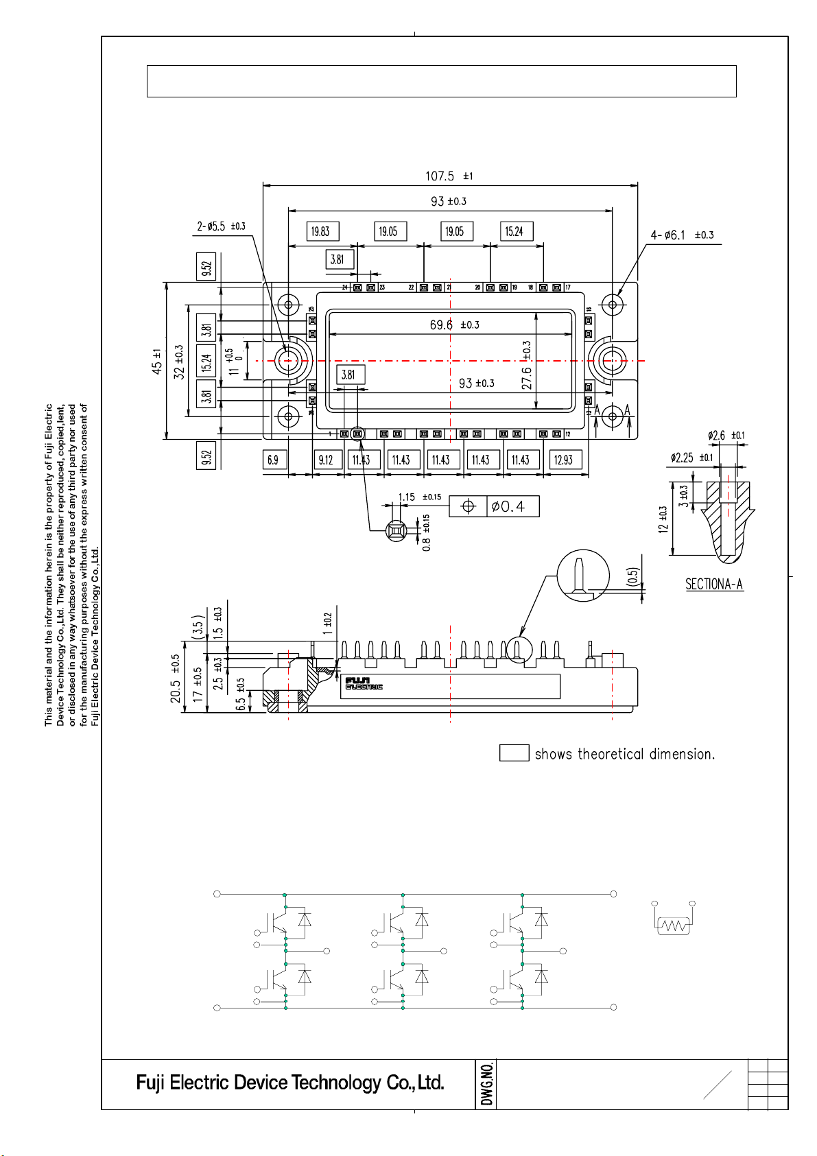
1. Outline Drawing ( Unit : mm )
6MBI75U2A-060
2. Equivalent circuit
222555,,,222666
222777,,,222888
( ) shows reference dimension.
111555,,,111666
111
222
333
444
555
666
UUU VVV WWW
222333,,,222444
777
888
999
111000
111111
111222
111999,,,222000222111,,,222222
111333,,,111444
111777 111888
3
MS5F 5743
13
H04-004-03a
Page 2

3.Absolute Maximum Ratings ( at Tc= 25°C unless otherwise specified
Items Symbols Conditions
VCESCollector-Emitter voltage
Gate-Emitter voltage
Collector current
Collector Power Dissipation
Junction temperature
Storage temperature
Isol ati on
voltage
Screw
Torque
(*1) All terminals should be connected together when isolation test will be done.
(*2) Two thermistor terminals should be connected together, each other terminals should be connected together
and shorted to base plate when isolation test will be done.
(*3) Recommendable Value : 2.5~3.5 Nm (M5)
between terminal and copper base *1
between thermistor and others *2
Mounting *3 3.5
VGES
Ic
Icp
-Ic 75
-Ic pulse
Pc
Tj
Tstg
Viso
-
)
Continuous
1ms
AC : 1min.
Maximum
Ratings
600
±20 V
75
150
150
255
150
-40 ~ +125
2500 VAC
Units
V
A
W1 device
°C
N m
4. Electrical characteristics ( at Tj= 25°C unless otherwise specified)
Items Symbols
Zero gate voltage
Collector current
Gate-Emitter
leakage current
Gate-Emitter
threshold voltage
Collector-Emitter
saturation voltage
Input capacitance Cies VCE=10V,VGE=0V,f=1MHz - 5.4 - nF
Inverter
Turn-on time
Turn-off time
Forward on voltage
Reverse recovery time trr -
Resistance R
Thermistor
B value T = 25/50°C
(*)Biggest internal terminal resistance among arm.
ICES
IGES
VGE(th)
VCE(sat)
(
terminal)
VCE(sat)
(chip)
ton
tr
tr (i)
toff
tf
VF
(terminal)
VF
(chip)
B 3305 3375 3450
VGE = 0V
VCE = 600V
VCE = 0V
VGE=±20V
VCE = 20V
Ic = 75mA
VGE=15V
Ic = 75A
Vcc = 300V
Ic = 75A
VGE=±15V
Rg = 47 Ω
VGE=0V
IF = 75 A
T = 25°C
T =100°C 465
Conditions
Tj= 25°C
Tj=125°C
Tj= 25°C
Tj=125°C
Tj= 25°C - 1.95 2.30
Tj=125°C
Tj= 25°C -
Tj=125°C
Characteristics
min.
-
- -
- 2.20 2.50
- 2.50
- 1.85 -
-
- 0.42
- 0.24
- 0.05
- 0.42
- 0.03 0.45
- 2.00
-
- 5000 -
-
2.15 -
1.60 -
1.65
- 0.35
4.1 - mΩLead resistance, terminal-chip * R lead -
495
max.typ.
1.0 mA
200
7.7 V6.2 6.7
-
1.20
0.60
-
1.20
-
-
520
Units
nA
V
µs
V
µsIF = 75 A
Ω
K
MS5F 5743
4
13
H04-004-03a
Page 3

5. Thermal resistance characteristics
Items Symbols Conditions
Thermal resistance(1device)
Contact Thermal resistance
Rth(j-c)
Rth(c-f) with Thermal Compound (*)
* This is the value which is defined mounting on the additional cooling fin with thermal compound.
IGBT
FWD
Characteristics
min. typ. max.
-
- - 0.79
- 0.05
6. Indication on module
Logo of production
6MBI75U2A-060
75A 600V
Lot.No. Place of manufacturing (code)
7.Applicable category
This specification is applied to IGBT Module named 6MBI75U2A-060 .
8.Storage and transportation notes
The module should be stored at a standard temperature of 5 to 35°C and humidity of 45 to 75% .
・
Units
- 0.49
°C/W
-
Store modules in a place with few temperature changes in order to avoid condensation on the module surface.
・
Avoid exposure to corr osive gas es and dust.
・
Avoid excessi ve external force on t he module.
・
Store modules with unprocessed terminals.
・
Do not drop or otherwise shock the modules when transporting.
・
9. Definitions of switching time
90%
~
~
0V
V
L
Vcc
R
G
V
GE
V
CE
Ic
GE
V
CE
Ic
0V
0A
ttt
rrrrrr
III
rrrrrr
rr
Ic
~
90%
10%
10% 10%
ttt
)))rrr(((iii
ttt
rrr
r
ttt
ooonnn
on
~
V
CE
~
~
ttt
oooffffff
off
10. Packing and Labeling
Display on the packing box
- Logo of production
- Type name
- Lot No
- Products quantity in a packing box
0V
90%
ttt
fff
MS5F 5743
5
13
H04-004-03a
Page 4

5
0
11. Reliability te s t r e s ults
Reliability Test Items
Test
categories
1 Term inal Stre ngth Pull force : 20 N
(Pull test) Test time : 10 ±1 sec.
2 Mounting S tren gth Screw torque : 2.5 ~ 3.5 N・m (M5)
3 Vibration Range of frequency : 10 ~ 500Hz
4 Shock Maximum acceleration :
Mechanical Tests
1 High T emperature Storage temp. : 12 5±5
Storage Test duration : 1 000 hr.
2 Low Tem perature Storage temp. : -40 ±5
Storage Test duration : 1 000 hr.
3 Tempe ra tu re Storage temp. : 85±2
Humidity Relative humidity : 85±5%
Storage Test duration : 1 000 hr.
4 Unsaturated Test temp. : 120±2
Pressure Cooker Atmospheric pressure :
5 Tempe ra tu re
Cycle Test temp. : Low temp. -40±5
Test items Test methods and conditions
Test time : 10 ±1 sec.
Sweeping time : 15 min.
Acceleration :
100m/s
2
Sweeping direction : Each X,Y,Z axis
Test time : 6 hr. (2h r./direction)
5000m/s
2
Pulse width : 1.0m sec.
Direction : Ea ch X ,Y,Z a xis
Test time : 3 tim es/d irection
℃
℃
℃
℃
1.7 × 10⁵ Pa
Test humidity : 85 ±5 %
Test duration : 96hr.
℃
Reference
norms
EIAJ ED-4701
(Aug.-2001 edition)
Test Method 401
MethodⅠ
Test Method 402
methodⅡ
Test Method 403
Reference 1
Condition code B
Test Method 404
Condition code B
Test Method 201
Test Method 202
Test Method 103
Test code C
Test Method 103
Test code E
Test Method 105
Number
of
sample
5 ( 0 : 1 )
5 ( 0 : 1 )
5 ( 0 : 1 )
5 ( 0 : 1 )
5 ( 0 : 1 )
5 ( 0 : 1 )
5 ( 0 : 1 )
5 ( 0 : 1 )
5 ( 0 : 1 )
Acceptance
number
Environment Tests
6 Thermal Sho ck
High temp. 125 ±5
RT 5 ~ 35
℃
Dwell time : High ~ RT ~ Low ~ R T
1hr. 0.5hr. 1hr. 0.5hr.
Number of cycles : 100 cycles
Test temp. :
High temp. 100
Low temp. 0
+0
-
+5
-
℃
Used liquid : W ater with ice and boiling water
Dipping time : 5 min. p ar each te mp.
Transfer time : 1 0 sec.
Number of cycles : 10 cyc les
℃
℃
Test Method 307
method Ⅰ
Condition code A
5 ( 0 : 1 )
6
MS5F 5743
13
H04-004-03a
 Loading...